Article

Design and Analysis of a Novel Microspeaker with Enhanced Low-Frequency SPL and Size Reduction

School of Mechanical Engineering, Pusan National University, Busan 46241, Korea
*
Author to whom correspondence should be addressed.
Appl. Sci. 2020, 10(24), 8902; https://doi.org/10.3390/app10248902
Submission received: 16 November 2020 / Revised: 10 December 2020 / Accepted: 12 December 2020 / Published: 13 December 2020
(This article belongs to the Special Issue Modeling, Design and Control of Electric Machines)

Abstract

:

Featured Application

This novel microspeaker can be used in future portable devices, such as smartphones, tablet PCs, and smartwatches that require enhanced acoustic performance, while reducing the speaker exterior size.

Abstract

In the era of multimedia devices, smartphones have become the primary device for consuming multimedia content. As technological developments have facilitated a more immersive multimedia experience, enlarged displays and the use of several sensors have limited the allowable size of microspeakers. Although sound plays an important role when consuming multimedia content, the limited space for microspeakers in modern devices leads to poor acoustic performance, especially at low frequencies. To address this issue, this paper proposes a novel microspeaker structure that enhances the low-frequency sound pressure level (SPL), while also featuring reduced exterior dimensions. The structure was designed and analyzed using 3D finite element analysis. Through coupling analysis, the simulation results were verified on the basis of the experimental results. The novel microspeaker has one outer magnet surrounding the entire coil, unlike in prototype microspeakers, which have two outer magnets. The gap between the top plates and coil is reduced, and a new type of coil is introduced for the purpose of increasing electromagnetic force. The samples were manufactured, and their SPLs were tested in an anechoic chamber. The experimental results prove that the proposed microspeaker offers an improved SPL at low frequencies compared with prototype microspeakers.

1. Introduction

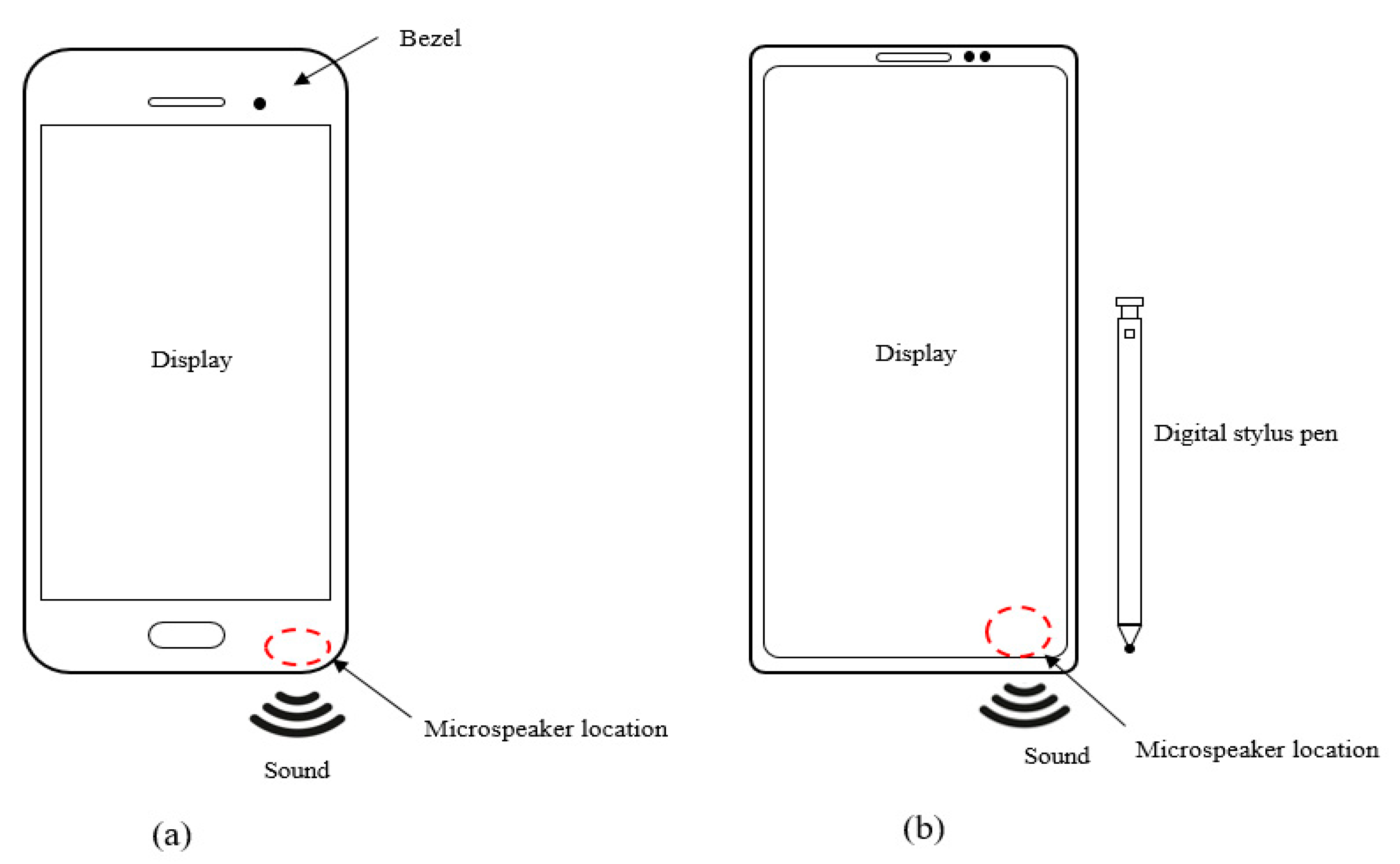
With the introduction and development of portable wireless devices, mobile devices have become essential to daily life. As many people use these devices to perform various tasks, the devices serve as a personal computer (PC). Currently, an increasing number of people use these portable wireless devices, especially smartphones, to consume multimedia content. Owing to the increased demand for multimedia content, production of entertainment content such as games, music, and videos has also increased. Sound plays an important role in providing an immersive experience for users, particularly low-frequency sound. Thus, sound is an important consideration for consumers when selecting a smartphone. Usually, a microspeaker is located at the bottom of the smartphone and is responsible for generating sounds when needed.
In the earlier versions of cellular phones, a round microspeaker was used. Hwang et al. introduced and analyzed circular and elliptical microspeakers [1]. To improve the sound pressure level (SPL), Hwang et al. also introduced a microspeaker with a new magnetic circuit [2]. Instead of using only the outer magnet, they also added a central magnet to increase the magnetic force [2]. To improve the space utilization in cellular phones, Kwon et al. developed a rectangular microspeaker [3]. Furthermore, Lee and Hwang developed a rectangular microspeaker in enlarged liquid-crystal displays that has modified structures to improve the acoustic performance, and new structures were added to the yoke to improve the flux density [4]. To develop thinner speakers for cellular phones, Lee et al. proposed a novel magnetic circuit in which the top plate was eliminated [5]. To reduce the thickness, Lee et al. used horizontally magnetized outer magnets instead of vertically magnetized outer magnets [5]. Advances in material research have also prompted engineers to use new materials in microspeakers. A piezoelectric speaker was developed for use in very thin devices [6,7]. The piezoelectric speaker has a multilayer structure that is thinner than the prototype microspeaker structure. However, this type of speaker is not widely adopted, owing to its high cost and poor acoustic performance at low frequencies. For a smartphone with a bezel-less display, indirect- and direct-vibration actuators were introduced and analyzed [8,9]. Compared with a microspeaker that generates sound by vibrating the diaphragm attached to the coil, these actuators are attached to the display panel, which generates sound by vibrating the elastic display panel. Microspeakers are widely used in other products. One example is a wearable device called the neckband. A neckband speaker with a passive vibrator was designed and analyzed by Kim et al. using Klippel measurement equipment [10]. The effect of the diaphragm material on the loudspeaker performance was analyzed by Wang et al. for a better frequency response [11]. Diaphragms with micro-corrugations were analyzed by Bae et al. to determine the effects on the acoustic performance [12]. In terms of the sound quality of the speaker module, one study proposed and optimized an L-shaped module [13]. To analyze a speaker system, Hernandez et al. proposed a method to obtain the nonlinear parameters in the speaker system, such as the force factor. Nonlinear parameters are defined as a function of the voice coil displacement [14]. With the advances in computational power, Reddy et al. were able to conduct an analysis of the acoustic performance of a microspeaker using a machine learning algorithm [15].
Previously, devices contained few components, which restricted the size of the microspeakers. In addition, the thicker bezels around the display afforded sufficient space for the microspeaker. However, owing to the demand for larger displays, bezel-less displays were introduced, and many components, such as digital stylus pens, need to be mounted on the smartphone. The design changes of the smartphones are shown in Figure 1.
For this reason, the allowable size of microspeakers has decreased, and prototype microspeakers can no longer be used in newer smartphones. Owing to this design shift, smartphones require smaller speakers, especially in terms of length and height. However, size reduction necessitates a reduction in the magnetic circuit structure, resulting in low acoustic performance over all frequencies. Low-frequency sound is important for providing immersive experience when consuming multimedia content. Thus, in this study, a novel microspeaker with reduced exterior dimensions was designed to improve the low-frequency SPL.
For enhancement of the low-frequency SPL for microspeakers, the magnetic circuit structure must change to increase the force. In this paper, a novel magnetic circuit structure is proposed. The introduction of a new magnetic circuit accompanied many design changes, including the coil, top plates, yoke, and permanent magnet. To improve the electromagnetic force, we designed a ring-shaped permanent magnet, and the distance between the top plates and the coil was reduced. In addition, a new type of coil was used to increase the force. These design elements can be applied in many future microspeaker products requiring smaller size but with improved low-frequency SPL.
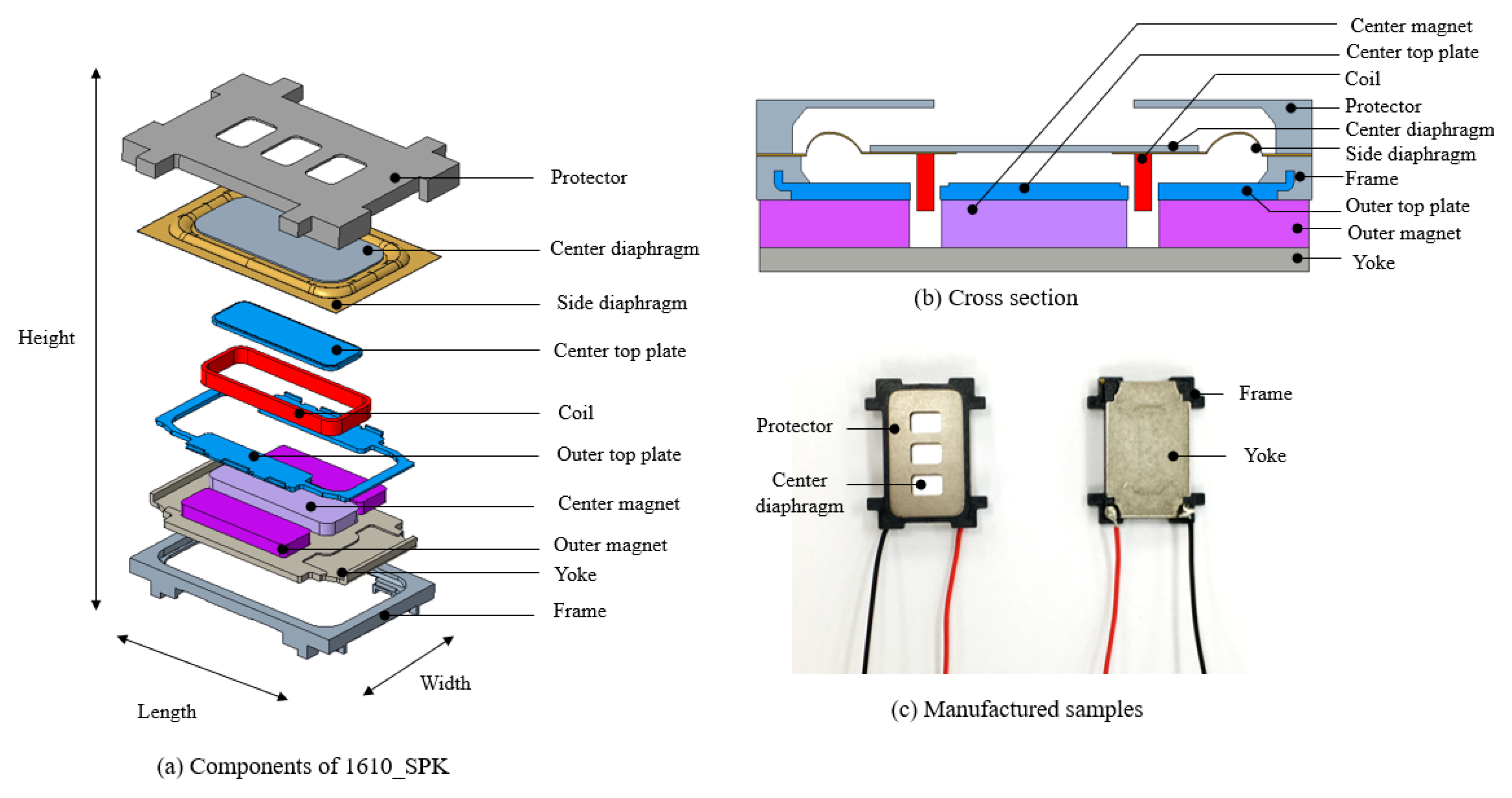
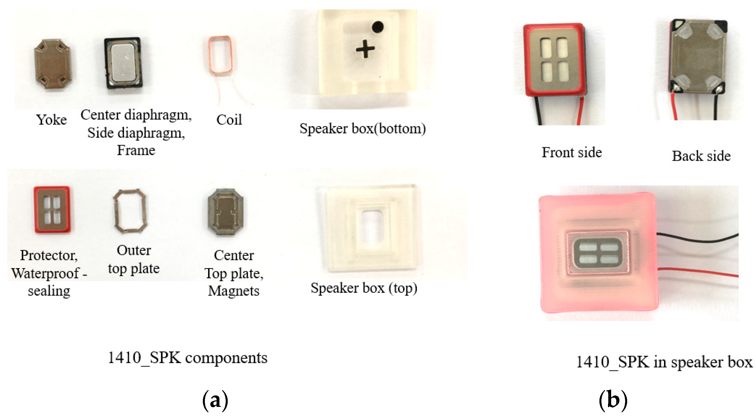
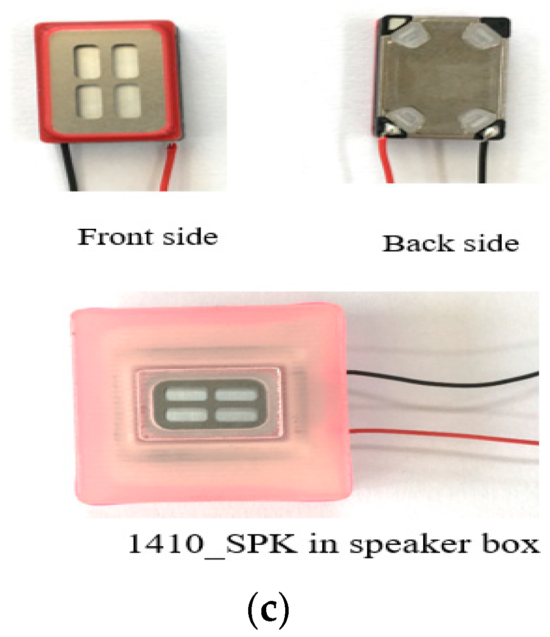
The prototype speaker, termed 1610_SPK, mainly consists of a coil, three neodymium permanent magnets, a center diaphragm, a side diaphragm, a yoke, and top plates. The prototype 1610_SPK has a length of 16.0 mm, a width of 10.0 mm, a height of 2.11 mm, and a coil resistance of 6.0 Ω. The coil and diaphragms are the moving components in 1610_SPK. The coil is attached to the diaphragms, and the vibration from the coil vibrates the diaphragms, which, in turn, generates sound. The remaining components are fixed and stationary. The design of the prototype 1610_SPK, its components, and manufactured samples are presented in Figure 2.

2. Analysis Method (Prototype)

Analysis of the microspeaker was conducted by solving three domains: electromagnetic domain, mechanical domain, and acoustic domain. Three domains were coupled with specific parameters called the force factor and the effective diaphragm area. To calculate the SPL, three domains should be solved simultaneously using coupled analysis. This means that coupled analysis is used for solving a multiphysics system. The coupled analysis was based on solving the domains described in Figure 3, and the flow chart (procedures) of the coupled analysis is shown in Figure 4. The electromagnetic and mechanical domains were expressed as circuits with resistors, voltage sources, capacitors, and inductors. On the basis of the impedance analogy, the mechanical domain was formed in the circuit. The acoustic domain was modeled under 3D simulating experimental conditions for the SPL measurement. The parameters in each domain were found in advance before the coupled analysis to obtain the SPL. The prototype 1610_SPK was used in the analysis method.

2.1. Electromagnetic Analysis

The governing equation for the electromagnetic analysis is expressed as follows:
V e = I R + L d I d t + B l ( z ) d z d t
where V e , I, R, L, t, l, and z are the voltage, current, resistance, inductance, time, coil length, and displacement, respectively. The vibration of the coil generates a back electromotive force (back EMF), which is expressed as B l ( z ) d z d t t in Equation (1). The back EMF is the product of the force factor and the velocity in the z-direction, derived in the mechanical domain. Equation (1) is called the voltage equation, and it can be described as a circuit shown in Figure 3 in the electromagnetic domain. To solve the voltage equation, we identified the parameters in advance.
The flux density was obtained by using a finite element method (FEM)-based commercial software (Ansys). The flux density in the coil was obtained by solving the following governing equations:
B = × A
× H = J
B = μH
where B is the magnetic flux density, × is the vector curl operation, A is the magnetic vector potential, J is the current density, H is the magmatic intensity, and μ is the magnetic permeability. The flux linkage is defined as follows:
λ ( z , I ) = N S B ( z , I )
where N is the number of coil turns, S is the coil cross-sectional area, and B is the average flux density passing through the coil. The inductance is expressed as the derivative of the flux linkage to the displacement expressed in Equation (4):
L = d λ d I
The force that causes coil vibration is the Lorentz force. If the direction of the current flowing in the coil and the direction of the magnetic field are known, the direction of the Lorentz force can be determined. The force factor is derived by dividing the Lorentz force by the current. They are expressed as
F L o r e n t z = I d l × B F o r c e   f a c t o r = F L o r e n t z / I = B l
The material properties needed for the electromagnetic analysis are listed in Table 1.
The top plates and the yoke were made of SPCC (Steel Plate Cold Commercial) and had a nonlinear relationship between B and H. B and H were correlated with a nonlinear parameter called magnetic permeability. This nonlinear value was calculated from the slope of the BH curve. The BH curve of SPCC is shown in Figure 5.
A sphere shape domain was made around the microspeaker to simulate the air region. At the surface of the air region, we applied a magnetic insulation boundary condition, meaning that the flux was tangential to its boundaries. The hexahedral element was used at the coil, magnet, and center diaphragm because of its simple shape. For the rest of the parts, a tetrahedral element was used because of the complexity of its boundary shape. Because the electromagnetic force was calculated from the coil, we used the fine element size in the coil. In addition, the top plates and the yoke that provide paths for the magnetic fluxes were also finely meshed for accurate results. The type of element, element size, and element number for the analysis are listed in Table 2.
The average flux density on the coil of the prototype 1610_SPK was found to be 0.560 T. The flux density on the coil and its distribution in the cross section are shown in Figure 6. The results of the force factor and inductance are shown in Figure 7.

2.2. Mechanical Analysis

In the mechanical analysis, the system was formed with lumped parameters of mass, stiffness, and damping. The governing equation is expressed as follows:
M d 2 z d t 2 + C d z d t + K z = F L o r e n t z ( t )
where M, C, K, and z are the mass coefficient, damping coefficient, stiffness coefficient, and displacement, respectively. The force in the mechanical domain is the Lorentz force from the electromagnetic analysis. The mechanical system of the microspeaker included a center diaphragm, a side diaphragm, and a coil. The governing equation (Equation (6)) can be described as a circuit in the mechanical domain shown in Figure 3 using the impedance analogy.
The lumped parameters of the mechanical system (M, C, and K) were measured using Klippel measurement equipment. Klippel measurement equipment is a laser-based measurement device that includes a power amplifier (PLX 1802), the Distortion Analyzer 2 (H1-DA2), and a laser scanner. For the measurement, electric wires were connected to the microspeaker, which was fixed using the stationary jig. The laser point was positioned at the center of the diaphragm. Figure 8 shows the Klippel equipment and its settings. Ten manufactured prototype 1610_SPK samples were measured, and the measured values were averaged. The measurement results are listed in Table 3.

2.3. Electromagnetic–Mechanical–Acoustic Coupled Analysis

The electromagnetic and mechanical domains were coupled with a force factor. The force factor is in the governing equations as a form of back EMF and Lorentz force in Equations (1) and (6). In the acoustic domain, the volume velocity was coupled with the velocity from the mechanical domain. The acoustic pressure was calculated using the force. The relationships can be written as
P = F L o r e n t z S d
v v o l u l m e = S d d z d t
where P is the acoustic pressure, S d is the effective diaphragm area, and v v o l u l m e is the volume velocity. These two equations are coupled with the effective diaphragm area S d . Thus, an effective diaphragm area of 1610_SPK should be found. Jiang et al. suggested a method to obtain an effective diaphragm area [16]. Figure 9 illustrates how to determine the effective diaphragm area ( S d ) and its boundary conditions for mechanical FEM analysis.
Figure 9a is adapted from “Analysis and Design of Helmholtz Protector to Improve High-Frequency Response of Insert Earphone,” Jiang, Y.-W., Xu, D.-P., Jiang, Z.-X., Kim, J.-H. and Hwang, S.-M. 2019, Appl. Sci., 9(12), p. 2541.
The S d of 1610_SPK was found using a FEM-based commercial software (Ansys). The material properties needed for the analysis are listed in Table 4. The effective diaphragm area of 1610_SPK was found to be 95.96 mm2.
For the SPL analysis, the electromagnetic and mechanical domains were modeled as equivalent circuits, and the acoustic domain was modeled in 3D using the FEM-based software, as shown in Figure 3. Because the microspeaker SPL was measured in an anechoic chamber, the sound emitted from the microspeaker was not reflected and was absorbed by the chamber walls. To simulate the experimental conditions in the FEM software, we made a sphere-shaped air region with its boundary condition of spherical wave radiation directed outward in the acoustic domain. In addition, the baffle plate used in actual experimental conditions was simulated as a hard boundary wall in the software. The SPL measurement point was made at a distance of 0.1 m away from the speaker. After obtaining all the parameters needed for the coupled analysis, we calculated the SPL using FEM software (Virtual.Lab). In the software, each domain was modeled as shown in Figure 3.

3. Experimental Verifications (Prototype)

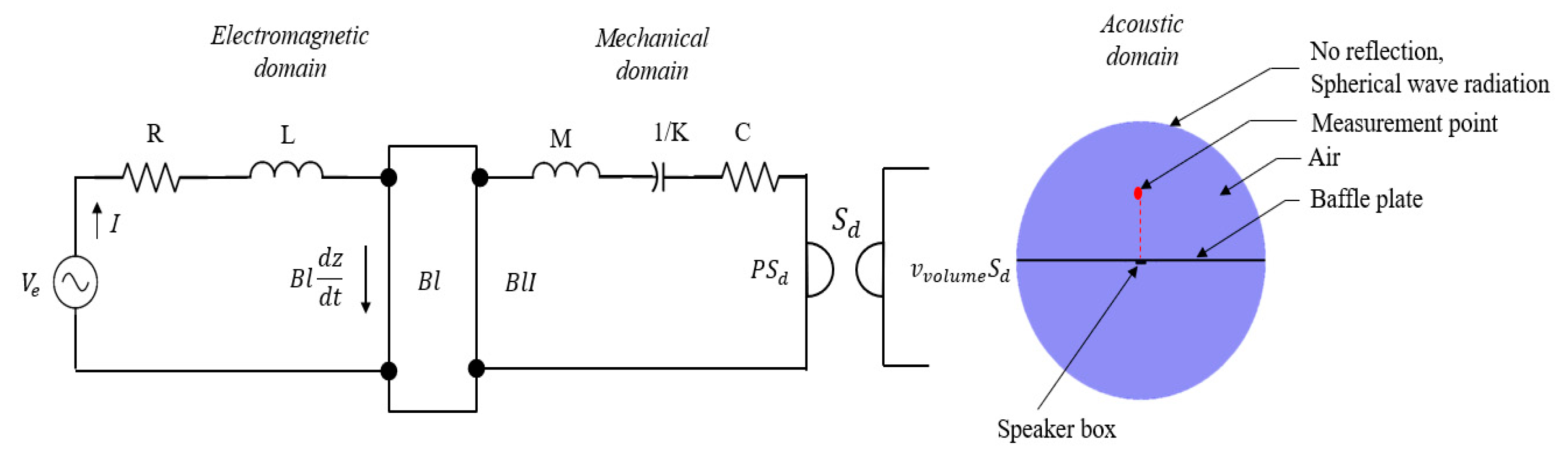
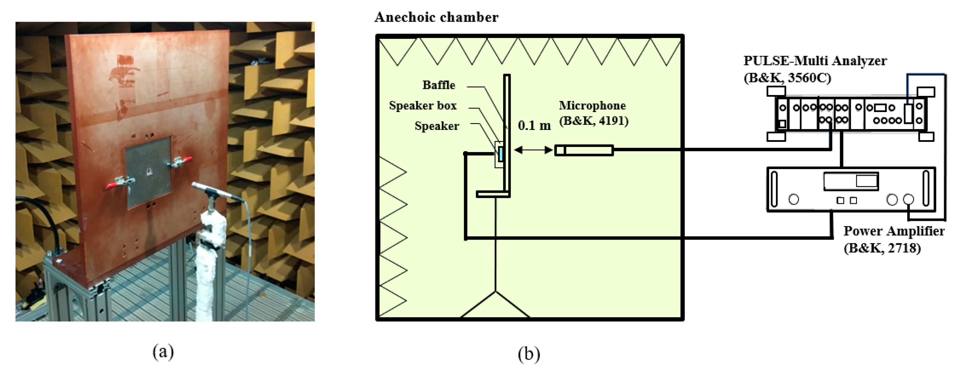
The experiment for measuring the SPL was conducted in an anechoic chamber. The electric wires were connected to the prototype 1610_SPK for the input signals, and the speaker was inserted into the speaker box with a back volume of 0.6 cc. The speaker was fixed with a baffle plate using clamps. The microphone for measuring the SPL was located at a distance of 0.1 m along the central axis of the microspeaker.
Sinusoidal signals ranging from frequencies of 100 Hz to 20,000 Hz were applied to the speaker with an input voltage of 3.1 Vrms. To obtain sufficient data in the overall frequency range, we used 1/12 octave for the input frequency resolution.
The experimental system (B&K system) used for measuring the SPL consisted of a power amplifier (B&K, 2718), a microphone (B&K, 4191), and the PULSE Multi-Analyzer system (B&K, 3560C). In the B&K system, the sound signal from the microphone was transformed into SPL data in the frequency domain via a fast Fourier transform. The sampling frequency of the microphone was 48 kHz. 
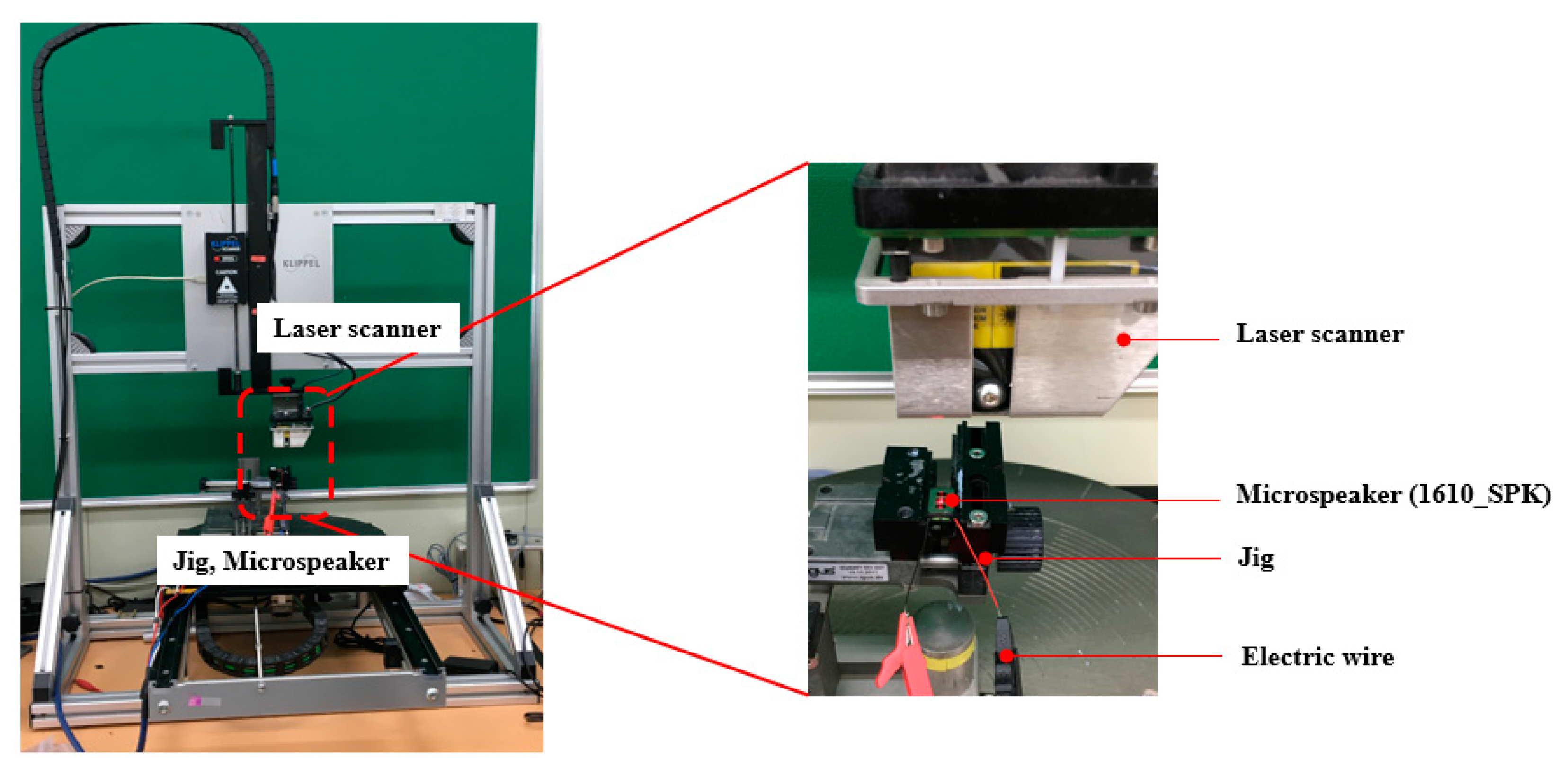
Figure 10 shows the experimental setup and measurement system connections. Ten prototype 1610_SPK samples were used in the experiment, and the SPL was measured three times for each sample. The measured SPL was averaged at each tested frequency.
The acoustic performance of the microspeaker at low frequencies can be represented by an arithmetic mean (average) of the SPL from four frequencies: 200 Hz, 300 Hz, 500 Hz, and 700 Hz. The average SPL of the prototype 1610_SPK from the four frequencies was found to be 77.92 dB. Table 5 shows the SPL of 1610_SPK at four frequencies and its averaged value.
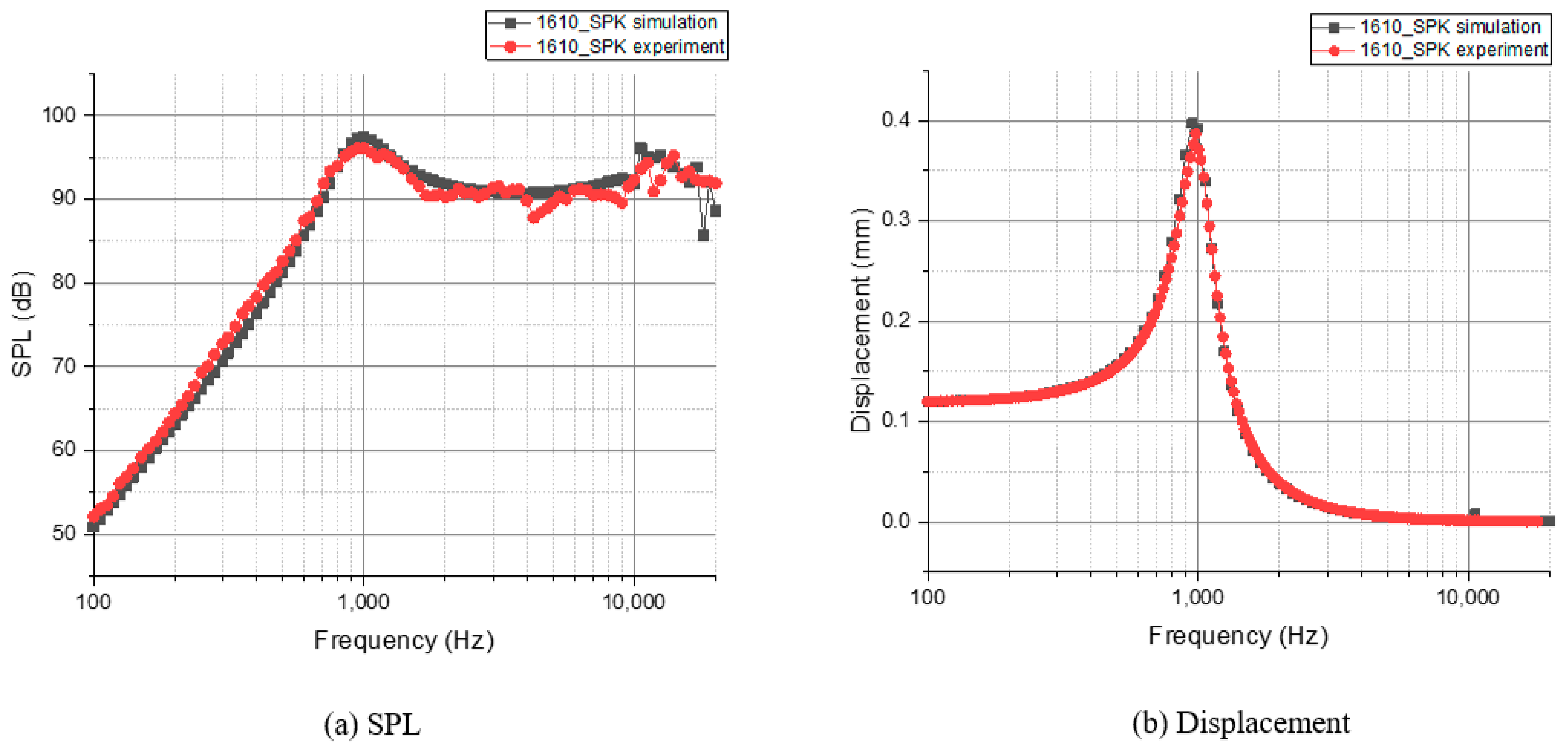
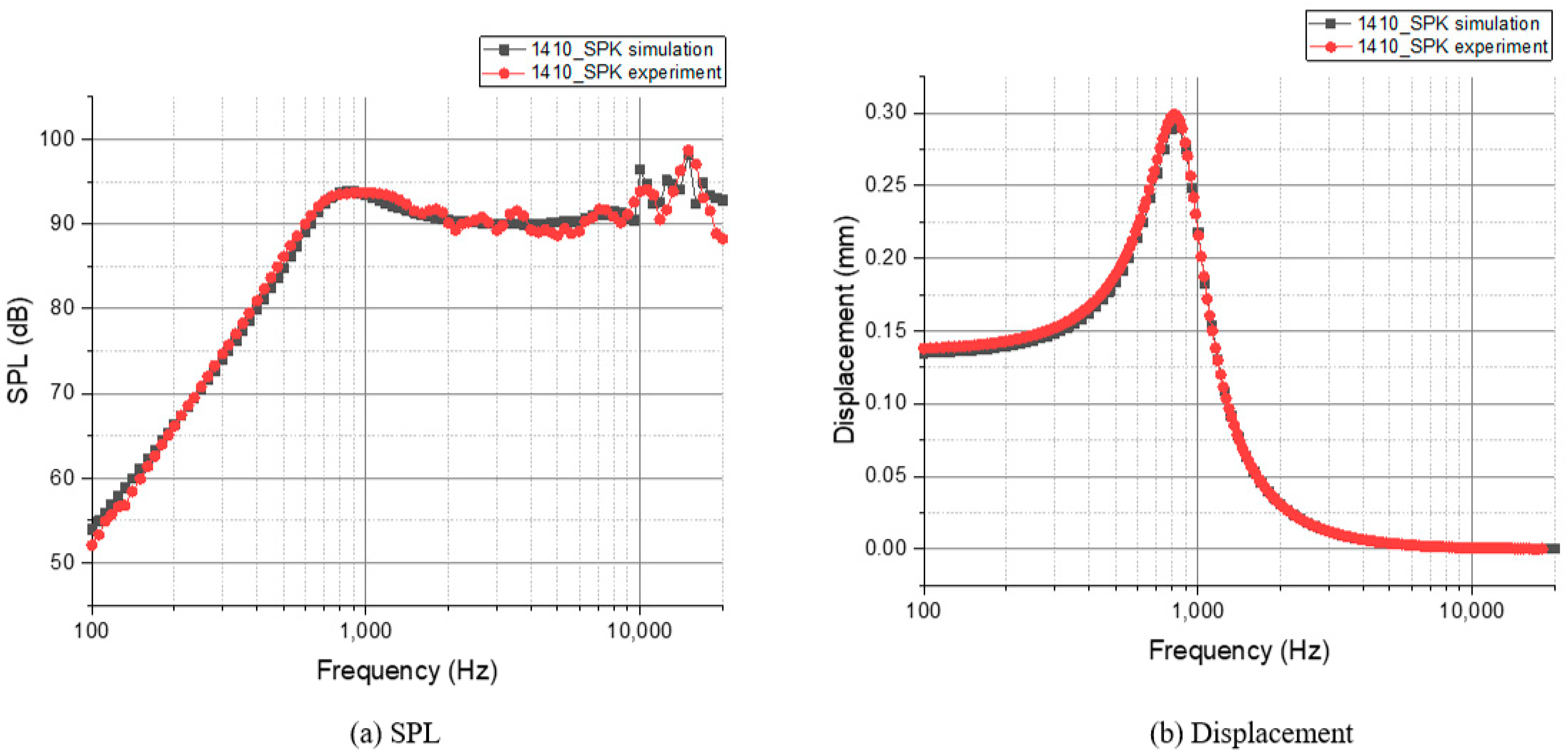
The simulation and experimental results for the overall frequencies are shown in Figure 11. The results were found to be well matched in terms of the SPL and displacement. This indicates that the analysis method can be used to predict and analyze other speaker models.

4. New Microspeaker Design

The size of a speaker affects its performance, i.e., the SPL. A large speaker typically has better performance owing to the larger magnets, top plates, yoke, coil, and other components. Large magnets can generate a greater Lorentz force. In contrast, small speakers limit the dimensions of the magnets, yoke, top plates, and coil, resulting in a lower Lorentz force. To increase the low-frequency SPL while reducing the speaker dimensions, we needed to consider the structures as well as other design factors. The proposed microspeaker, 1410_SPK, was designed with a length of 14 mm, width of 10 mm, and height of less than 2.1 mm. For this design of 1410_SPK, we considered the magnetic circuit structure, air gap, and coil. The flux density and the force were calculated at z = 0 mm (initial position) with an input voltage of 3.1 Vrms.

4.1. Magnetic Circuit Structure Design

The Lorentz force (electromagnetic force) is the force that drives the coil vibration. To increase the Lorentz force, the flux density passing through coil B or the total coil length l need to be increased. As the design of the speaker coil determines both the flux density and the total coil length, it is important to appropriately design the coil to maximize the Lorentz force. In addition, the low-frequency SPL can be improved by using a heavier coil. By adopting a large-diameter coil, the mass and total length of the coil are increased simultaneously. However, this increased coil diameter leads to an increased thickness and height of the coil, which causes a low flux density, resulting in a decreased Lorentz force. The schematics of the coil are shown in Figure 12.
For the proposed microspeaker, 1410_SPK, a 0.077-mm coil diameter was used, unlike the 0.070-mm coil used in 1610_SPK. By using this coil with a larger diameter, we increased the mass and length of the coil by approximately 51% and 25%, respectively, compared with those of the prototype 1610_SPK. The coil specifications of 1610_SPK and 1410_SPK are listed in Table 6. Because a coil with a larger diameter and the same resistance of 6 Ω was used, the height of 1410_SPK exceeded that of 1610_SPK, making it unsuitable for newer smartphones. The yoke thickness around the coil and also the distance between the upper part of the yoke and the bottom surface of the coil were reduced for solving the height problem. 
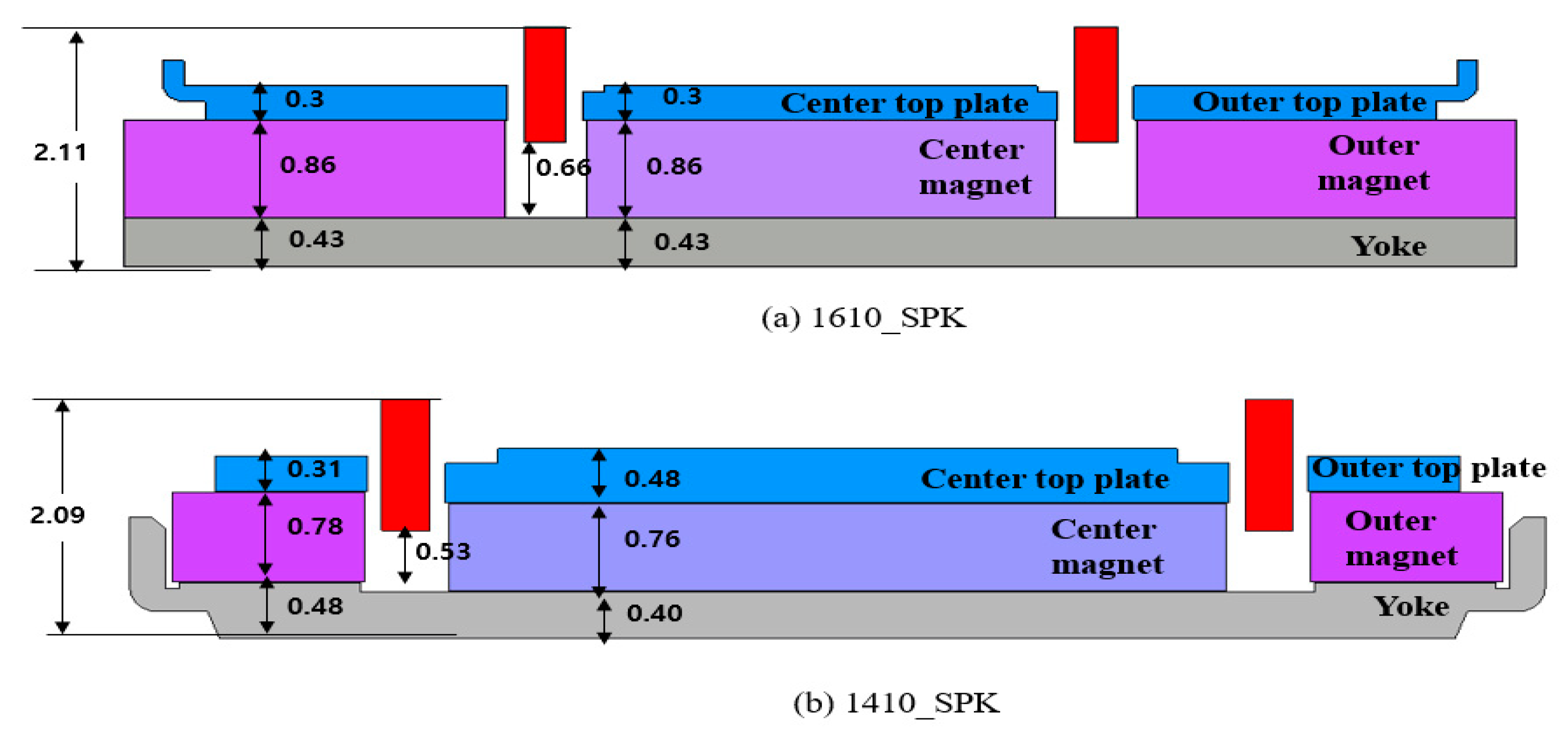
Figure 13 shows the component thicknesses for 1610_SPK and the newly designed 1410_SPK. As shown in this figure, the distance between the bottom of the yoke and the top surface of the coil in 1410_SPK was less than that in 1610_SPK.
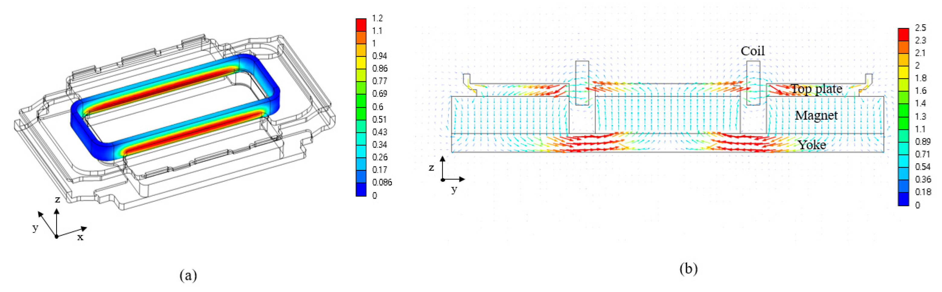
The magnets in the speaker are the main source of magnetic flux. The generated magnetic flux is concentrated on the coil through the top plates. The prototype 1610_SPK has a total of three permanent magnets: one center magnet and two outer magnets. 
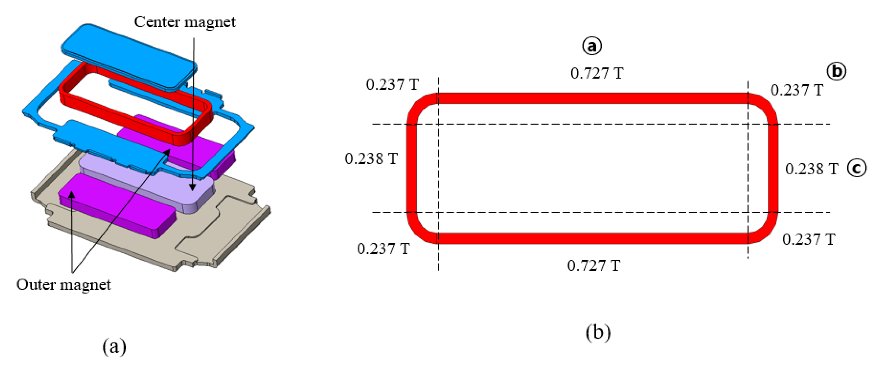
Figure 14 depicts the design of 1610_SPK and the average flux density distribution on the coil, which is divided into eight sections. Because the design of 1610_SPK is symmetric, the coil flux density is also symmetric. As shown in Figure 14b, the longer part of the coil is labeled as section ⓐ, the corner part as section ⓑ, and the shorter part as section ⓒ for comparison purposes. Over the entire coil, 1610_SPK has an average flux density of 0.560 T.
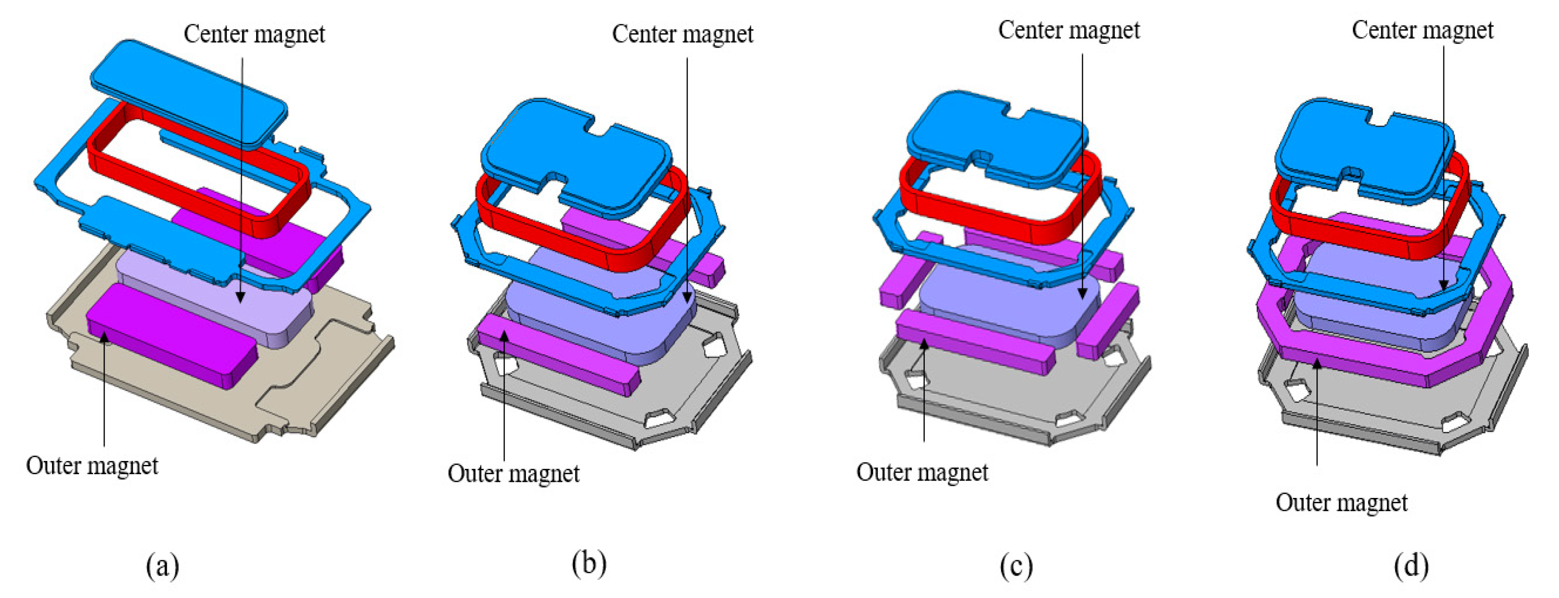
As in 1610_SPK, one center magnet and two outer magnets were deployed in 1410_SPK. The design of 1410_SPK with a total of three magnets, called 1410_SPK_3mag, is shown in Figure 15b. Owing to the reduction in the length of the speaker from 16.0 to 14.0 mm, we used smaller outer magnets compared with those in 1610_SPK. Owing to the smaller outer magnets, the flux density of 1410_SPK_3mag was lower than that of the coil in 1610_SPK. Although the average flux density in 1410_SPK was 13.4% lower than that in 1610_SPK, the longer coil length resulted in a 4.6% larger force.
As shown in Figure 14b, the shorter part of the coil (section ⓒ) has a lower flux density than that of the longer part (section ⓐ). This is because there are no outer magnets in section ⓒ. This can also be seen in Figure 15b. To increase the flux density in section ⓒ, we added two additional outer magnets, as shown in Figure 15c; thus, 1410_SPK features a total of five magnets. This resulted in a 10.8% increase in the total force compared with that when using the 1410_SPK with two outer magnets.
The flux density at the corner (section ⓑ) can be improved by placing magnets around the corner side of the coil. For the flux density improvement around the corners, we designed an additional ring-shaped outer magnet. This magnet was implemented such that it surrounded the entire coil, leading to a 13.8% improvement in the total force, compared with that when using the 1410_SPK with two outer magnets. To make a ring-shaped magnet, first, the exterior shape was made by cutting the outside of the permanent magnet. After creating an exterior shape, a thin wire was inserted into the center of the magnet and the inside part was cut out, resulting in a ring-shaped magnet. The flux density distribution in each section and the total force results are listed in Table 7. Overall, the result of the magnetic structure analysis showed that the total force improved by approximately 19% when using the large-diameter coil and the ring-shaped outer magnet that surrounds the entire coil. Thereafter, an air-gap design analysis for 1410_SPK_2mag was conducted.

4.2. Air Gap Design

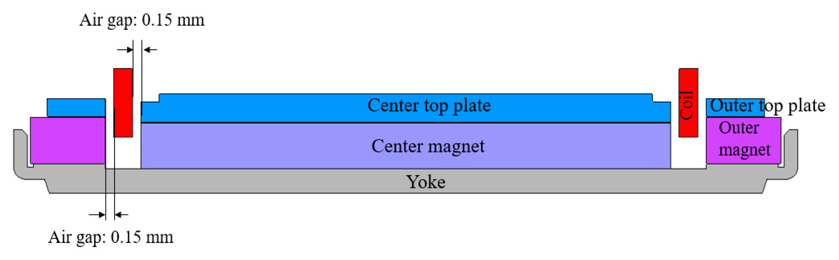
The top plates and the yoke, which are made of SPCC, are the important components of the microspeaker structure. The magnetic flux generated by the permanent magnets is concentrated on the coil through the top plates and the yoke. The air gap refers to the distance between the top plate and the coil, as shown in Figure 16. In microspeaker designs, the distance between the coil and the top plate is the same as that between the magnets and the coil. Additional center top plates, outer top plates, center magnets, and outer magnets can be used if the air gap is decreased, as a decreased air gap can improve the total force. The air gap of 1610_SPK was 0.15 mm. Previously, the achievable minimum air gap was 0.15 mm, owing to the manufacturing technology at that time. During the manufacturing process, the coil is inserted between the center top plate and the outer top plate, and then the air gap is manually checked by human eyes using a tool maker microscope (Mitutoyo).
Advances in manufacturing technology have enabled the reduction of the air gap in speaker designs, owing to the tightly controlled tolerances of modern jigs and molds. The air gap is reduced using new automated machines that inspect the air gap during manufacturing. Owing to the new automated visual inspection machine (Hirox), the air gap can be reduced from 0.15 to 0.10 mm. Reducing the air gap concentrates more magnetic flux in the coil, resulting in a higher force. In the analysis, the coil dimensions were fixed, and the air gap was gradually reduced. The results of the flux density and the force acting on the coil when the air gap was reduced from 0.15 to 0.1 mm are presented in Table 8.
The results show that reducing the air gap from 0.15 to 0.10 mm increased the force by approximately 8.7%. Subsequently, 1410_SPK with two permanent magnets (a ring-shaped outer magnet and a center magnet) and an air gap of 0.10 mm was subjected to coil design analysis.

4.3. New Coil Design

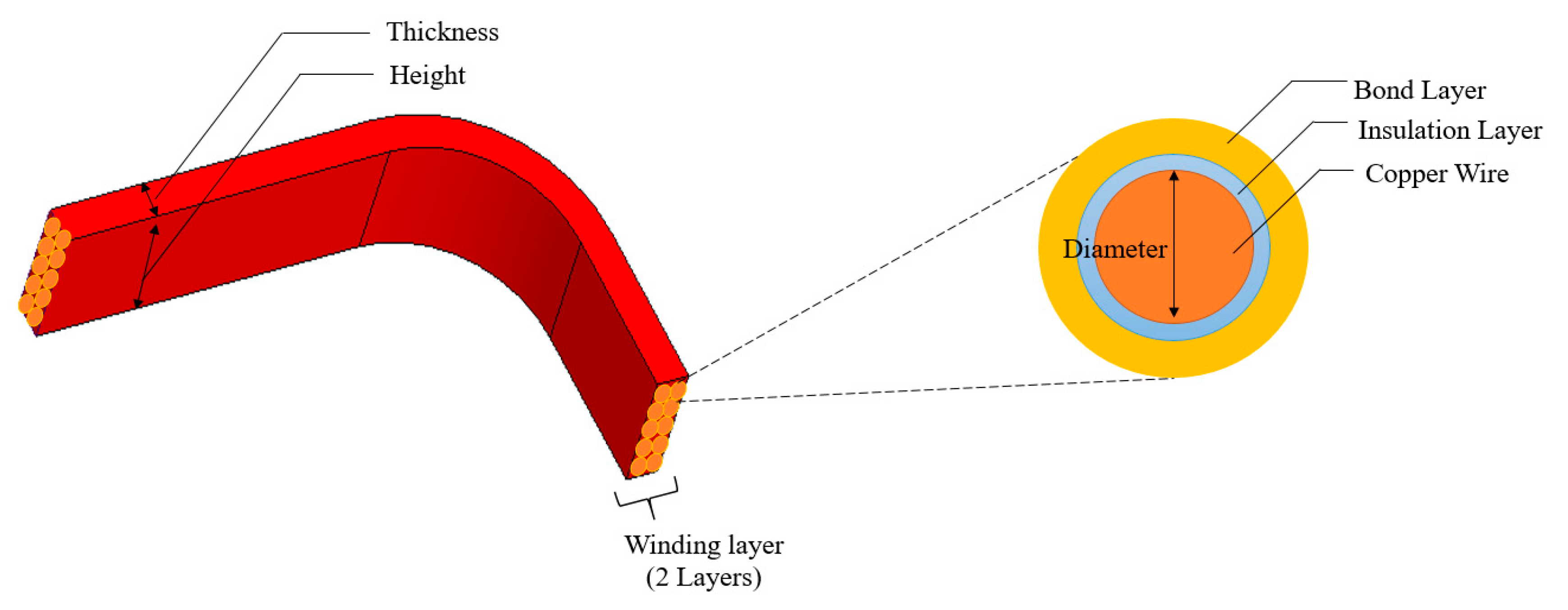
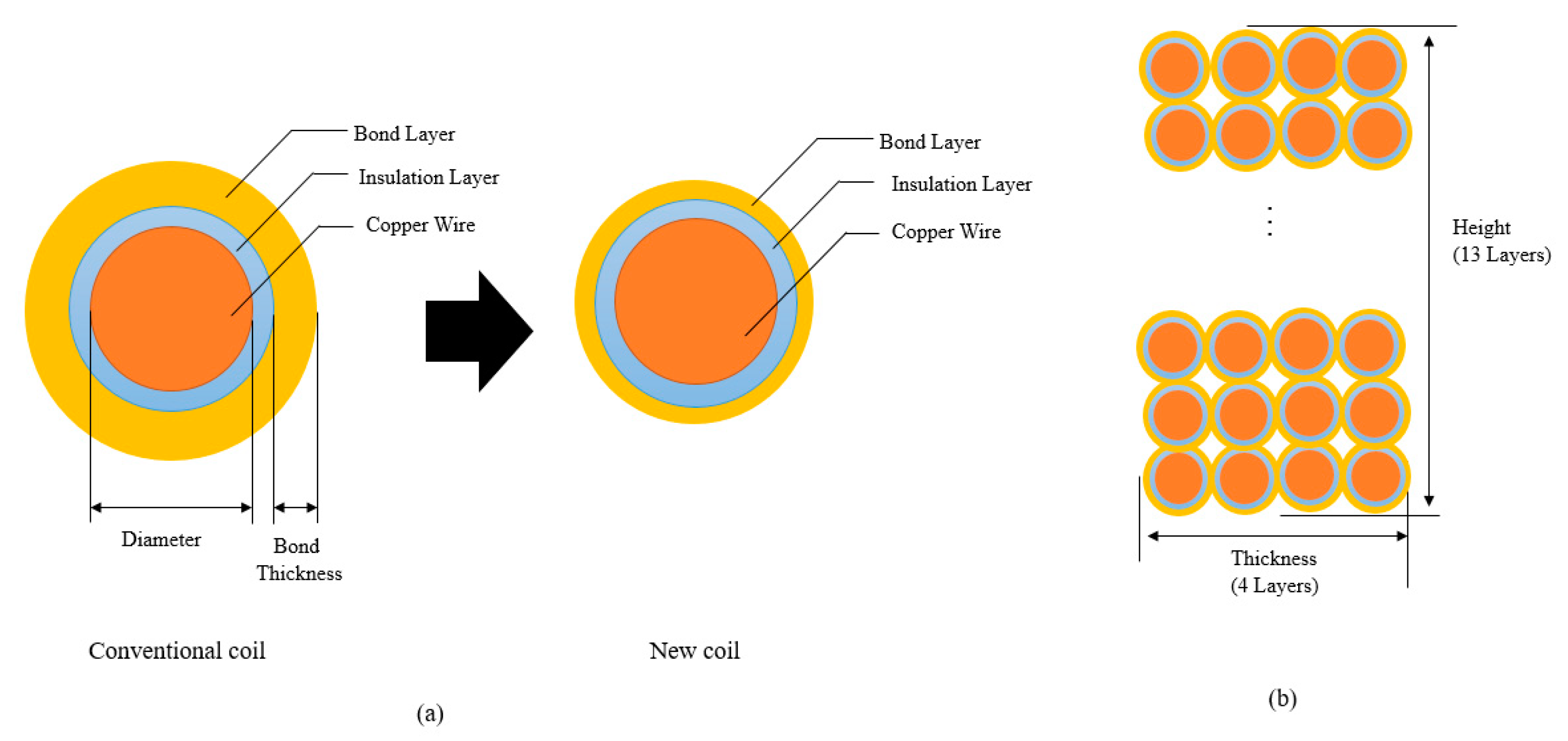
The coil consists of three main components: copper for the current flow, an insulation layer, and a bond layer. Owing to advances in technology, a coil with a thinner bond layer has been introduced, which enables a reduction in the coil height and thickness compared with the dimensions of the conventional coil used in 1610_SPK. A comparison between the conventional and the new coil is shown in Figure 17a. Figure 17b depicts the coil winding cross section of 1410_SPK; except for the bond layer thickness, the thicknesses of the copper wires and insulation layers are similar.
The prototype 1410_SPK has 4 horizontal layers of coil as well as 13 vertical layers. When the conventional coil is used in 1410_SPK, the bond has a thickness of approximately 0.012 mm, which results in a thickness of 0.356 mm and a height of 1.16 mm. The bond layer of the new coil is approximately 25% thinner, at 0.009 mm; in other words, for the same resistance, the newly designed coil offers reduced exterior dimensions. For a coil diameter of 0.077 mm, the thickness and height are 0.344 mm and 1.12 mm, respectively. A reduction of over 3% was achieved in terms of thickness and height. The smaller coil enables the use of larger magnets and top plates, with an air gap of 0.10 mm. This results in a 2.4% higher force than that when using the conventional coil. Another approach to improve the force is to increase the total length of the new coil using a diameter greater than 0.077. Thus, the coil length can be increased while maintaining the same exterior dimensions as those for the conventional coil diameter of 0.077 mm. A diameter of 0.080 mm for the new coil matches the overall dimensions of the conventional coil with a diameter of 0.077 mm. The specifications for 1410_SPK when using the conventional and new coils are listed in Table 9.
The results show that using a diameter of 0.080 mm has a better force. The 1410_SPK with a diameter of 0.080 mm was chosen for the SPL experiment.

5. Samples and Experiment

On the basis of the analysis of the design, we manufactured 1410_SPK samples. Figure 18 depicts each component and the assembled 1410_SPK. For the SPL experiment, like with 1610_SPK, we placed 1410_SPK in a speaker box with a back volume of 0.6 cc. The experiment was conducted in an anechoic chamber using B&K equipment. The SPL results from the experiment and the simulation were in good agreement, as shown in Figure 19.

6. Results

The SPL of the prototype 1610_SPK and that of the newly designed 1410_SPK are compared in Figure 20. The average SPL of 1410_SPK at four low frequencies was found to be 79.79 dB. The SPL comparisons between 1610_SPK and 1410_SPK at four frequencies are listed in Table 10.
From the table, it can be seen that the SPL of 1410_SPK was higher by 1.87 dB at low frequencies than that of the prototype 1610_SPK. In terms of acoustic performance, the 1.87 dB improvement at low frequencies is a considerable improvement. This improvement was achieved via the heavier coil and the increased electromagnetic force, compared with those in 1610_SPK. At around 1000 Hz, the SPL of 1410_SPK was lower than that of 1610_SPK, owing to the damping of the SDP. Except around 1000 Hz, the SPL of 1410_SPK was similar to or better than that of its larger 1610_SPK counterpart. Overall, 1410_SPK yielded an improved SPL at low frequencies, while also featuring reduced speaker dimensions from 16.0 × 10.0 × 2.11 to 14.0 × 10.0 × 2.09 mm.

7. Conclusions

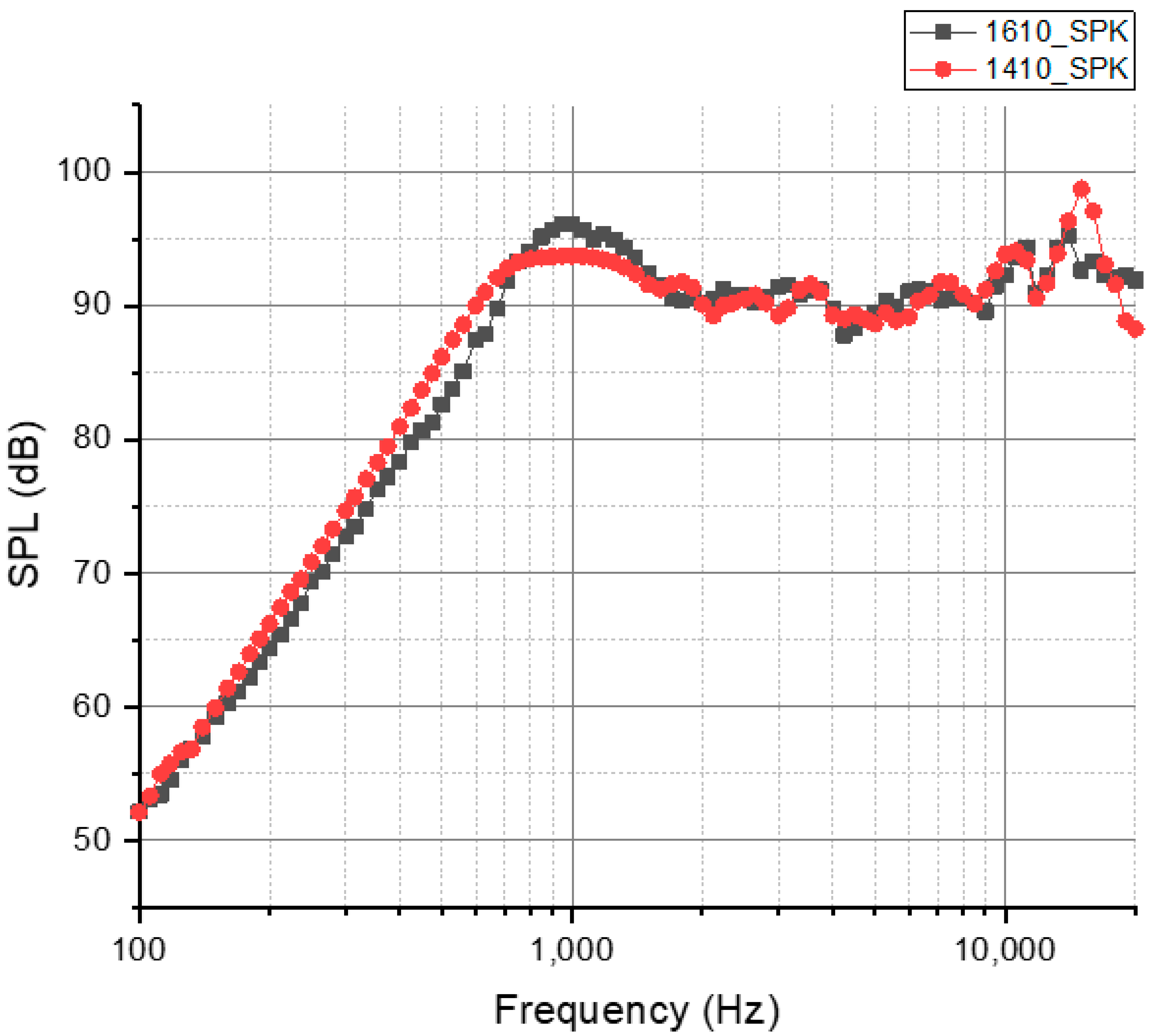
Smartphones have become daily necessities for many people. At present, acoustic performance has become an important feature when selecting smartphones. However, the bezel-less display and the numerous components, such as digital stylus pens, mounted in new-generation smartphones have decreased the allowable size of microspeakers. This reduced size degrades the acoustic performance of microspeakers, especially the SPL. To address this problem, we designed and tested a novel microspeaker, called 1410_SPK, in this study. This speaker aims to achieve an improved low-frequency SPL, while featuring reduced dimensions (relative to the prototype speaker). Coupled analysis was used to solve the multiphysics system of the microspeaker. The FEM analysis of the speaker and its SPL results were verified using the results of the experiment with the 1610_SPK prototype microspeaker. The electromagnetic force in the novel microspeaker (1410_SPK) was increased using a large-diameter coil. A ring-shaped permanent magnet that surrounds the exterior coil was used for flux density improvement. Furthermore, the air gap was reduced from 0.15 to 0.10 mm using an automated visual inspection machine. A coil with a thin bond layer was also introduced to increase the total force. The proposed 1410_SPK was manufactured, and its SPL was measured in an anechoic chamber. The SPL, which represents the low-frequency performance, was averaged from four frequencies. Comparison of the SPL proves that 1410_SPK offers an average SPL that is 1.87 dB higher than that of 1610_SPK. The 1.87 dB improvement at low frequencies is a considerable improvement considering the size reduction. Owing to the improved electromagnetic force, the smaller 1410_SPK has almost the same acoustic performance as that of 1610_SPK, except at frequencies around 1 KHz.
The results of this study on microspeakers can be applied to future portable devices such as smartphones, tablet PCs, or smartwatches that require small microspeakers with better acoustic performance.

Author Contributions

Conceptualization, K.-H.P., Z.-X.J., and S.-M.H.; methodology, K.-H.P.; software, K.-H.P. and Z.-X.J.; validation, K.-H.P. and Z.-X.J.; investigation, K.-H.P., and Z.-X.J.; writing—original draft preparation, K.-H.P.; writing—review and editing, K.-H.P., Z.-X.J., and S.-M.H. All authors have read and agreed to the published version of the manuscript.

Funding

This research received no external funding.

Conflicts of Interest

The authors declare no conflict of interest.

References

  1. Hwang, S.M.; Hwang, G.Y.; Kwon, J.H.; Lee, H.J.; Kang, B.S. Performance comparison between circular and elliptical type micro-speakers for cellular phones. IEEE Trans. Magn. 2003, 39, 3256–3258. [Google Scholar] [CrossRef]
  2. Hwang, S.M.; Lee, H.J.; Hong, K.S.; Kang, B.S.; Hwang, G.Y. New development of combined permanent-magnet type microspeakers used for cellular phones. IEEE Trans. Magn. 2005, 41, 2000–2003. [Google Scholar] [CrossRef]
  3. Kwon, J.H.; Hwang, S.M.; Kim, K.S. Development of slim rectangular microspeaker used for minimultimedia phones. IEEE Trans. Magn. 2016, 43, 2704–2706. [Google Scholar] [CrossRef]
  4. Lee, C.M.; Hwang, S.M. Development of advanced rectangular microspeakers used for wide liquid-crystal display mobile phones. J. Appl. Phys. 2011, 109, 07E504. [Google Scholar] [CrossRef]
  5. Lee, C.M.; Kwon, J.H.; Hwang, G.Y.; Hwang, S.M. Development of a new magnetic circuit for slim microspeakers. J. Appl. Phys. 2009, 105, 07E710. [Google Scholar] [CrossRef]
  6. Tseng, S.H.; Lo, S.C.; Wang, Y.J.; Lin, S.W.; Wu, M.; Fang, W. Sound Pressure and Low Frequency Enhancement Using Novel PZT MEMS Microspeaker Design. In Proceedings of the 2020 IEEE 33rd International Conference on Micro Electro Mechanical Systems (MEMS), Vancouver, BC, Canada, 18–22 January 2020; pp. 546–549. [Google Scholar] [CrossRef]
  7. Wang, H.; Li, M.; Yu, Y.; Chen, Z.; Ding, Y.; Jiang, H.; Xie, H. A Piezoelectric MEMS Loud Speaker Based on Ceramic PZT. In Proceedings of the 2019 20th International Conference on Solid-State Sensors, Actuators and Microsystems & Eurosensors XXXIII (TRANSDUCERS & EUROSENSORS XXXIII), Berlin, Germany, 23–27 June 2019; pp. 857–860. [Google Scholar]
  8. Kim, J.H.; Jiang, Y.W.; Hwang, S.M. Analysis and Design of New Actuator Used for Full-Wide Screen LCD. Appl. Sci. 2019, 9, 4599. [Google Scholar] [CrossRef] [Green Version]
  9. Park, K.H.; Jiang, Z.X.; Jiang, Y.W.; Hwang, S.M. Development of Direct-Vibration Actuator for Bezel-Less Display Panels on Mobile Phones. Appl. Sci. 2020, 10, 4975. [Google Scholar] [CrossRef]
  10. Kim, H.K.; Jiang, Y.W.; Xu, D.P.; Kwon, J.H.; Hwang, S.M. Practical Design of a Speaker Box with a Passive Vibrator. IEEE Access 2018, 6, 11443–11451. [Google Scholar] [CrossRef]
  11. Wang, C.; Chang, J.; Chang, W. Influences of Diaphragm Materials on the Performance of a Microspeaker. J. Mech. 2015, 31, 331–336. [Google Scholar] [CrossRef]
  12. Bae, H.J.; Lee, H.J.; Kim, S.K.; Park, K. Investigation on Acoustic Characteristics of Micro-Speaker Diaphragm according to Corrugation Depth Using Finite Element Analysis. J. Korean Soc. Precis. Eng. 2017, 34, 569–574. [Google Scholar] [CrossRef]
  13. Kim, D.C.; Jeong, H. An optimal design of the internal space in a micro-speaker module. Int. J. Precis. Eng. Manuf. 2015, 16, 1141–1147. [Google Scholar] [CrossRef]
  14. Hernandez, D.; Yu, Y.M.; Huang, J. Nonlinear parameters identification of moving coil miniature loudspeakers. In Proceedings of the 2017 2nd International Conference on Frontiers of Sensors Technologies (ICFST), Shenzhen, China, 14–16 April 2017; pp. 226–230. [Google Scholar]
  15. Reddy, B.G.; Sadashivappa, G.; Gunasekaran, S. Acoustic Performance Analysis of Micro Speaker Using Machine Learning Algorithms. In Proceedings of the 2020 12th International Conference on Computational Intelligence and Communication Networks (CICN), Wireless Networks, Bhimtal, India, 25–26 September 2020; pp. 408–415. [Google Scholar]
  16. Jiang, Y.W.; Xu, D.P.; Jiang, Z.X.; Kim, J.H.; Hwang, S.M. Analysis and Design of Helmholtz Protector to Improve High-Frequency Response of Insert Earphone. Appl. Sci. 2019, 9, 2541. [Google Scholar] [CrossRef] [Green Version]
Figure 1. Schematics of the change in smartphone design and microspeaker location: (a) design with thick bezels and (b) design with a bezel-less display and a digital stylus pen.
Applsci 10 08902 g001
Figure 2. Structure of 1610_SPK: (a) components, (b) cross-sectional view, and (c) manufactured samples.
Applsci 10 08902 g002
Figure 3. Equivalent circuit (electromagnetic and mechanical) and acoustic domain for the coupled analysis.
Applsci 10 08902 g003
Figure 4. Flow chart (procedures) of the coupled analysis.
Applsci 10 08902 g004
Figure 5. Nonlinear B-H curve of SPCC.
Applsci 10 08902 g005
Figure 6. Flux density distribution of 1610_SPK: (a) coil and (b) cross section.
Applsci 10 08902 g006
Figure 7. Results of the force factor and inductance of 1610_SPK: (a) force factor and (b) inductance.
Applsci 10 08902 g007
Figure 8. Experimental setup for the measurement using Klippel equipment.
Applsci 10 08902 g008
Figure 9. Method of determining the effective diaphragm area and its boundary conditions: (a) effective diaphragm area and (b) boundary conditions.
Applsci 10 08902 g009
Figure 10. Experimental setup and equipment connections for the SPL measurement: (a) experimental setup in an anechoic chamber; (b) B&K equipment connections.
Applsci 10 08902 g010
Figure 11. Experiment and simulation results of 1610_SPK: (a) SPL and (b) displacement.
Applsci 10 08902 g011
Figure 12. Schematic of the coil design.
Applsci 10 08902 g012
Figure 13. Schematic of the coil design: (a) 1610_SPK and (b) 1410_SPK.
Applsci 10 08902 g013
Figure 14. Flux density distribution in 1610_SPK: (a) magnet design and (b) flux density distribution over the coil.
Applsci 10 08902 g014
Figure 15. Magnetic circuit structures: (a) 1610_SPK, (b) 1410_SPK 3mag, (c) 1410_SPK 5mag, and (d) 1410_SPK_2mag (ring shape).
Applsci 10 08902 g015
Figure 16. The prototype 1410_SPK with an air gap of 0.15 mm.
Applsci 10 08902 g016
Figure 17. Schematic of the coil structures: (a) conventional and new coils and (b) cross-sectional view of the 1410_SPK coil winding.
Applsci 10 08902 g017
Figure 18. Final design of 1410_SPK and manufactured samples: (a) 3D model of 1410_SPK, (b) manufactured components for 1410_SPK, and (c) assembled sample.
Applsci 10 08902 g018aApplsci 10 08902 g018b
Figure 19. Experiment and simulation results of 1410_SPK: (a) SPL and (b) displacement.
Applsci 10 08902 g019
Figure 20. Comparison of the SPL for 1610_SPK and 1410_SPK.
Applsci 10 08902 g020
Table 1. Material properties used for the electromagnetic analysis.
PartMaterialPropertyValueUnit
Air-Permeability4π × 10−7H/m
Magnet (N52H)NdFeBRemanence1.45T
Top plateSPCCPermeabilityB-H curveH/m
YokeSPCCPermeabilityB-H curveH/m
CoilCopperPermeability4π × 10−7H/m
Table 2. Mesh and element used in the analysis.
PartElement TypeElement SizeElement Number
AirTetrahedral2.50 mm89.47 × 104
MagnetHexahedral0.50 mm3.70 × 104
Top platesTetrahedral0.25 mm2.97 × 104
YokeTetrahedral0.25 mm4.48 × 104
CoilHexahedral0.10 mm12.74 × 104
Center diaphragmHexahedral0.25 mm1.38× 103
Side diaphragmTetrahedral0.25 mm1.96 × 104
Table 3. Measured values of 1610_SPK using Klippel equipment.
VariableNameValueUnit
MMass54.90Mg
CDamping0.083kg/s
KStiffness1.130N/mm
Table 4. Material properties for finding the effective diaphragm area ( S d ).
PartMaterialYoung’s ModulusPoisson’s RatioDensity
CoilCopper126 GPa0.345321 kg/m3
Center diaphragmAluminum alloy 68.9 GPa0.33856.1 kg/m3
Side diaphragmTPEE compound0.003 GPa0.421223 kg/m3
Table 5. Sound pressure level (SPL) of the prototype 1610_SPK at four frequencies.
Frequency200 Hz300 Hz500 Hz700 HzAverage
SPL (dB)64.4072.7882.6291.8977.92
Table 6. Coil specification of 1610_SPK and 1410_SPK.
ModelDiameterWinding
Layer
Coil
Height
Coil
Thickness
MassTotal
Length
1610_SPK0.070 mm41.02 mm0.328 mm46.41 mg1339.3 mm
1410_SPK0.077 mm41.16 mm0.356 mm69.99 mg1675.7 mm
Table 7. Result of the force due to the changes in magnetic circuit structure designs.
Model1610_SPK1410_SPK_3mag1410_SPK_5mag1410_SPK_2mag
Magnet Number3352 (ring shape)
Center magnet Volume28.14 mm337.65 mm337.65 mm337.65 mm3
Outer magnet Volume39.29 mm319.24 mm330.26 mm334.35 mm3
Flux density at section ⓐ0.727 T0.598 T0.588 T0.586 T
Flux density at section ⓑ0.237 T0.365 T0.430 T0.470 T
Flux density at section ⓒ0.238 T0.405 T0.588 T0.598 T
Total flux density 0.560 T0.485 T0.538 T0.551 T
Force0.388 N0.406 N0.450 N0.462 N
Table 8. Changes in the flux density and force with respect to the air gap.
Air GapFlux DensityForce
0.15 mm0.551 T0.462 N
0.14 mm0.561 T0.470 N
0.13 mm0.571 T0.478 N
0.12 mm0.580 T0.486 N
0.11 mm0.590 T0.494 N
0.10 mm0.599 T0.502 N
Table 9. Specifications of 1410_SPK and result when using the conventional and new coils.
Model1410_SPK1410_SPK1410_SPK_
Coil typeConventionalNewNew
Diameter0.077 mm0.077 mm0.080 mm
Bond thickness0.006 mm0.0045 mm0.0045 mm
Coil height1.16 mm1.12 mm1.16 mm
Coil thickness0.356 mm0.344 mm0.356 mm
Coil mass69.99 mg69.92 mg81.21 mg
Coil total length1675.7 mm1675.7 mm1807.6 mm
Flux density0.599 T0.614 T0.599 T
Force0.502 N0.514 N0.541 N
Table 10. SPL comparisons between 1610_SPK and 1410_SPK at four frequencies.
Frequency1610_SPK1410_SPK
200 Hz64.40 dB66.20 dB
300 Hz72.78 dB74.69 dB
500 Hz82.62 dB86.16 dB
700 Hz91.89 dB92.83 dB
Average77.92 dB79.79 dB
Difference-+1.87 dB
Publisher’s Note: MDPI stays neutral with regard to jurisdictional claims in published maps and institutional affiliations.

