Experimental and Comparative Study of Rotor Vibrations of Permanent Magnet Machines with Two Different Fractional Pole/Slot Combinations

 ,
,  , ,
, ,
Abstract
:1. Introduction
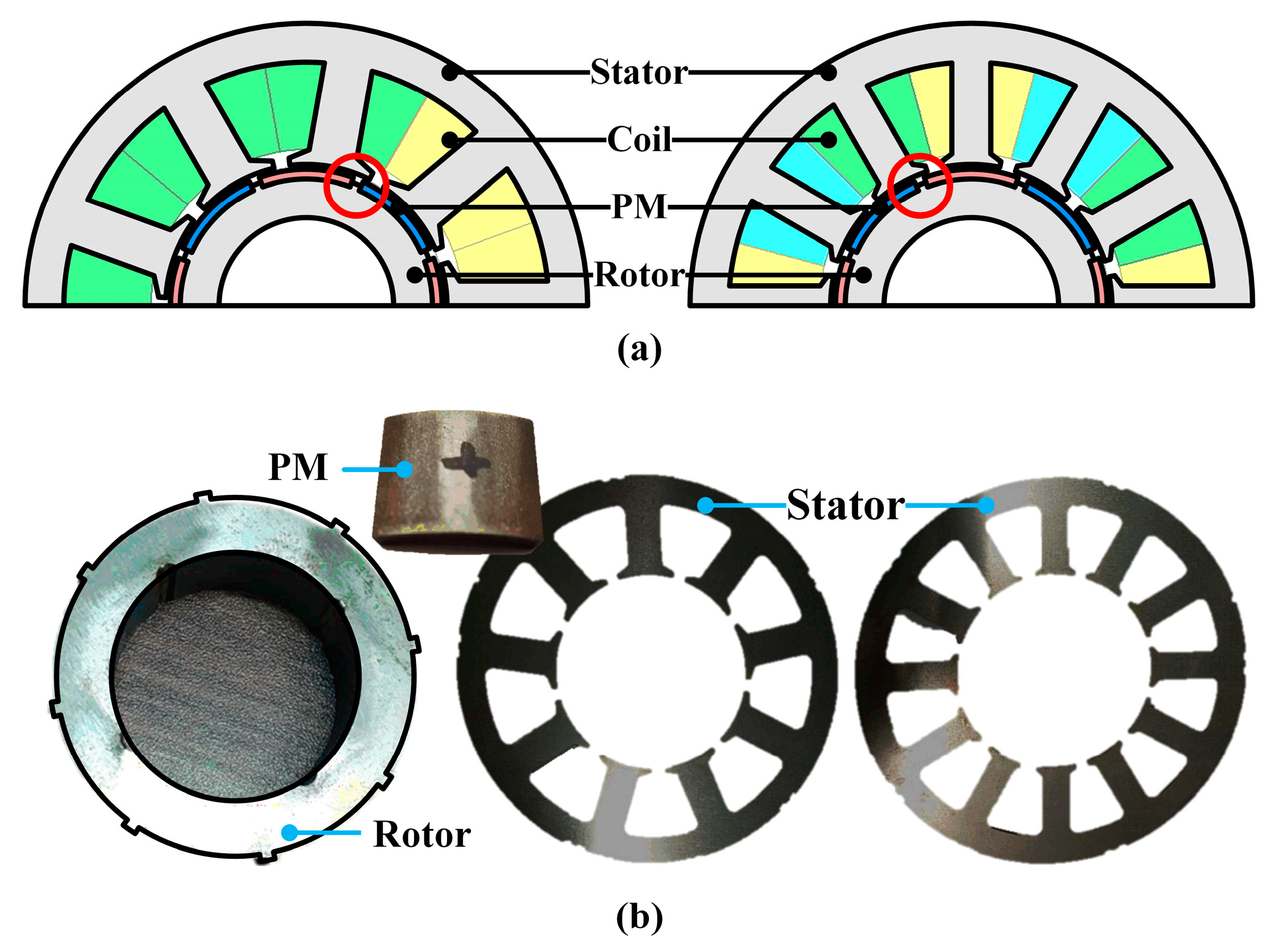
2. Comparative Electromagnetic Analysis
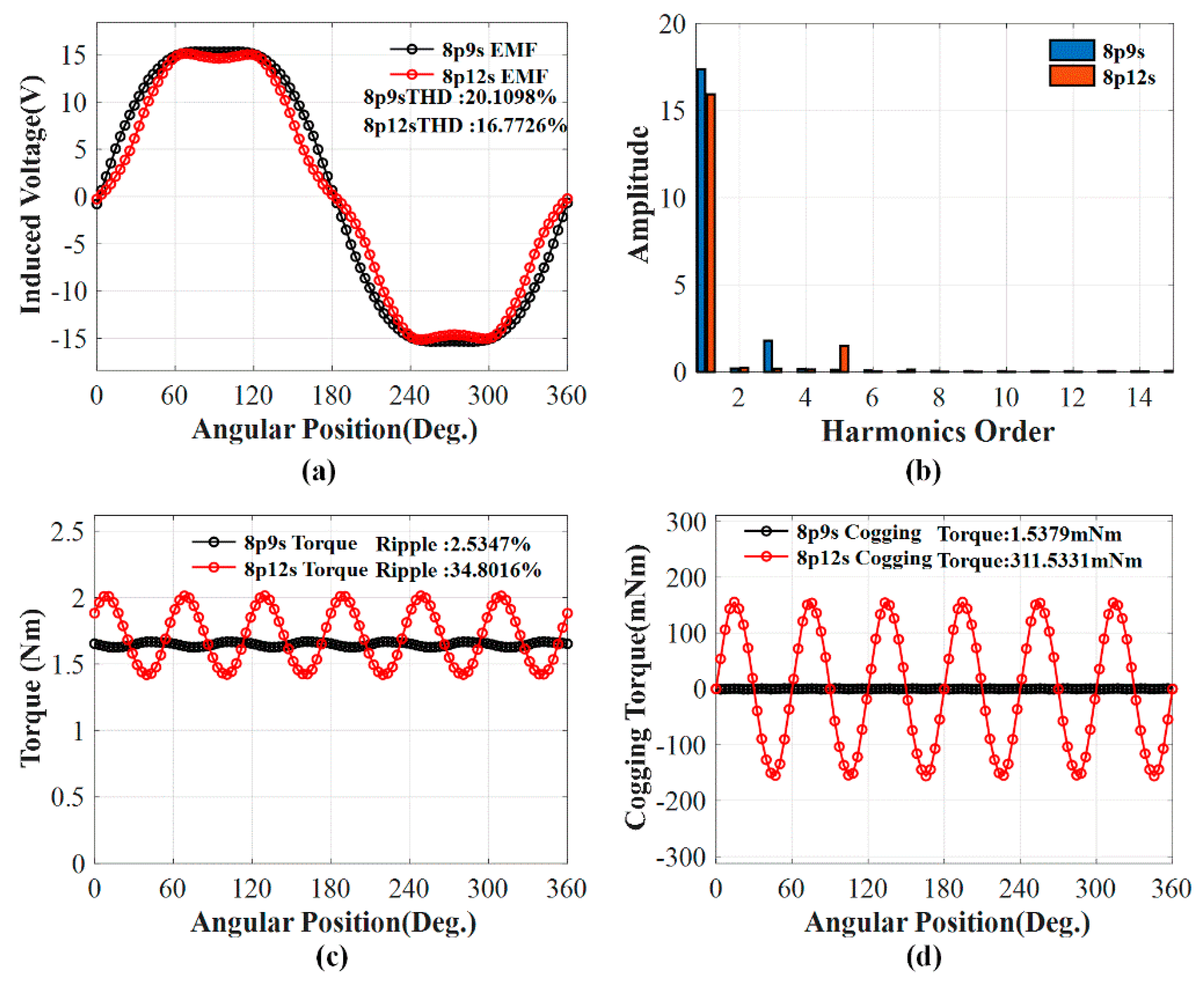
2.1. Back-EMF and Torque
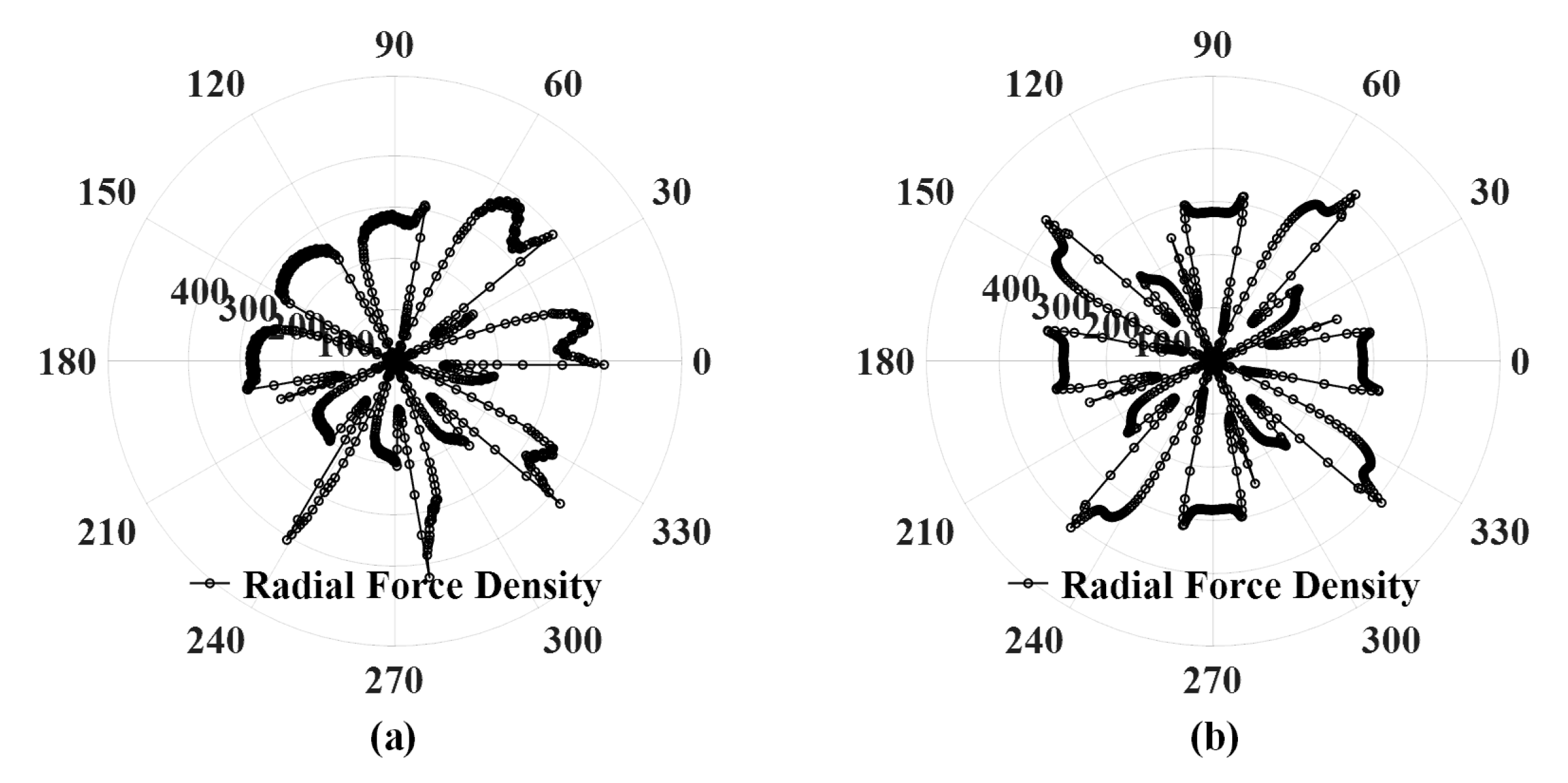
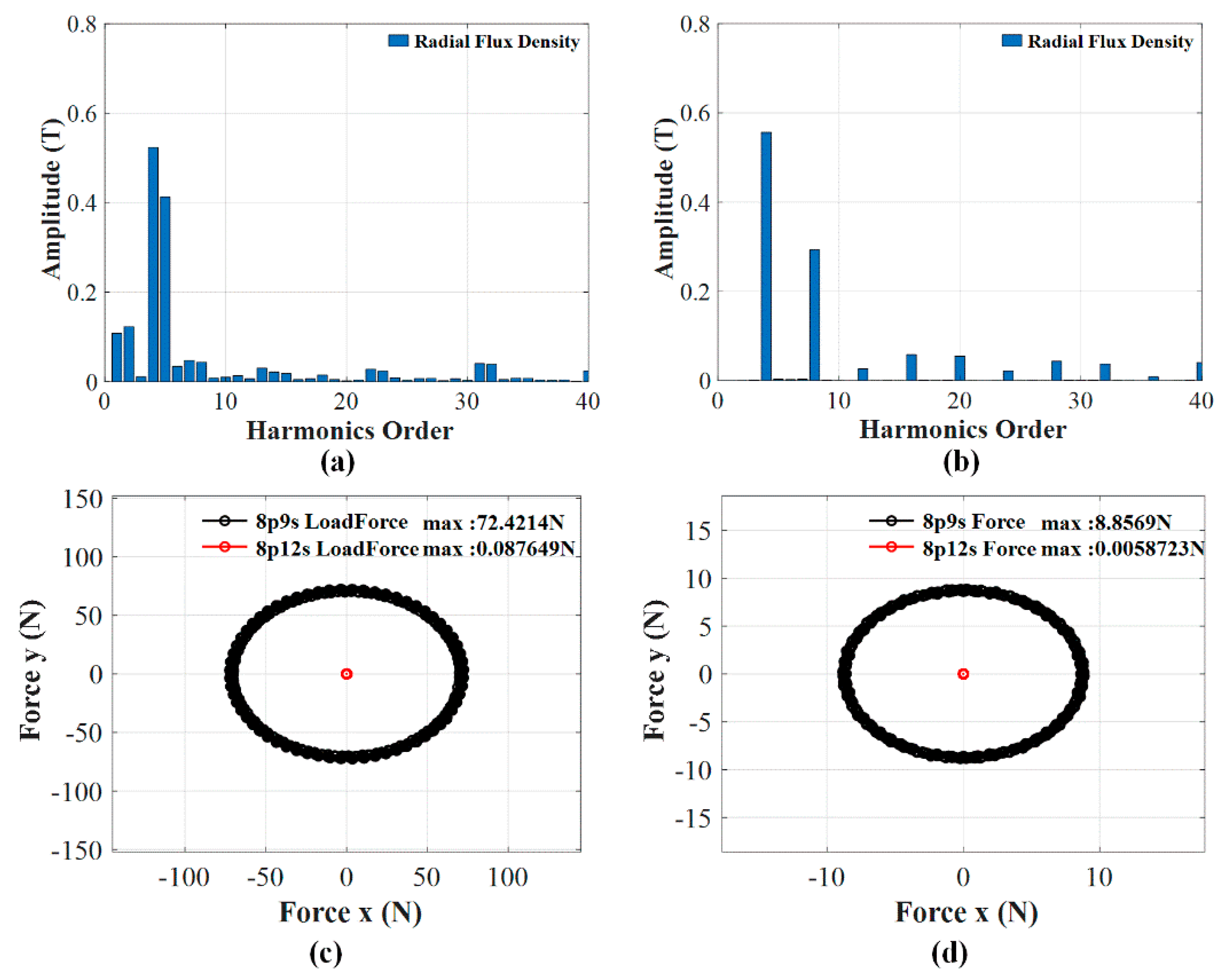
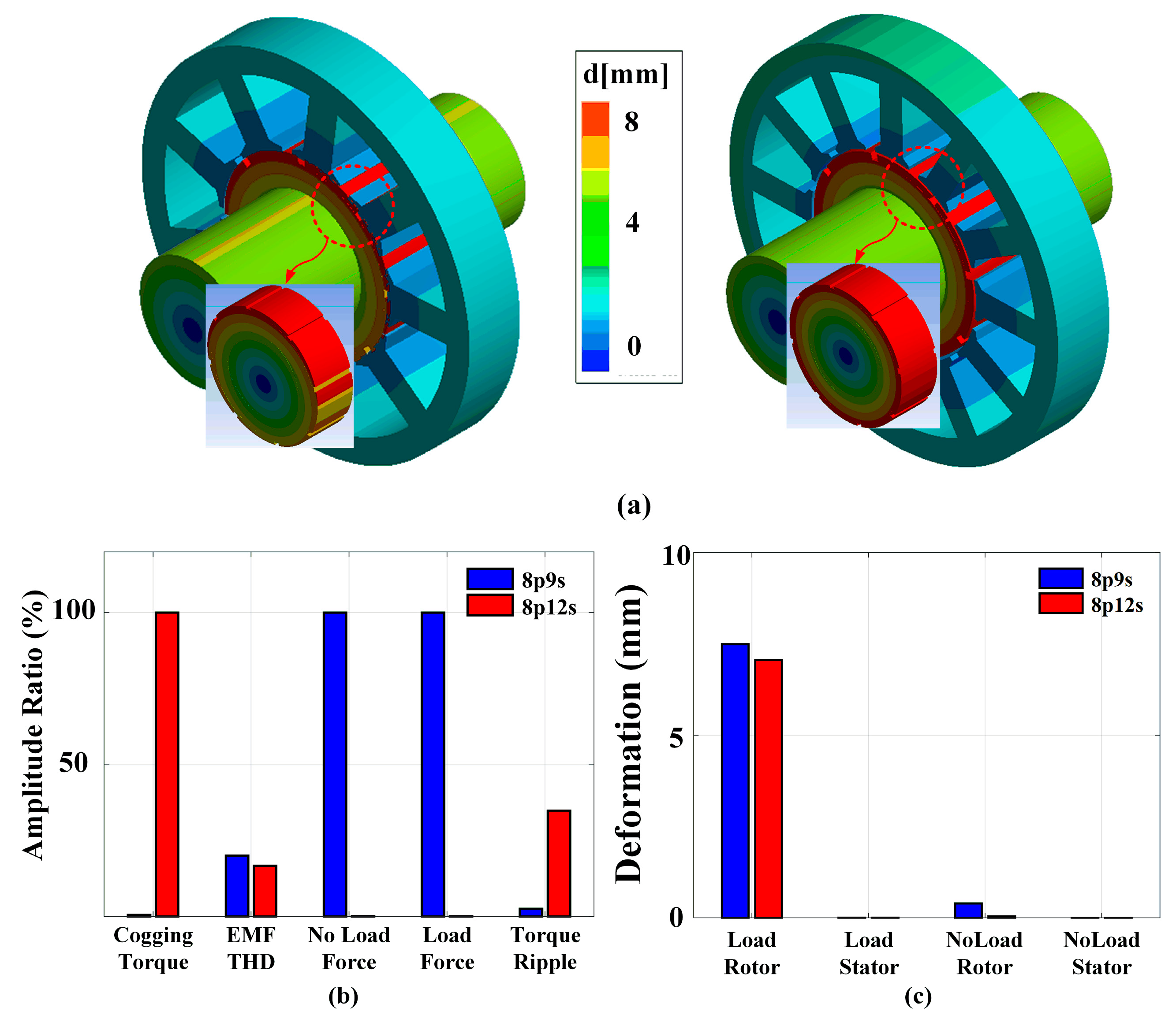
2.2. MPF and UMF
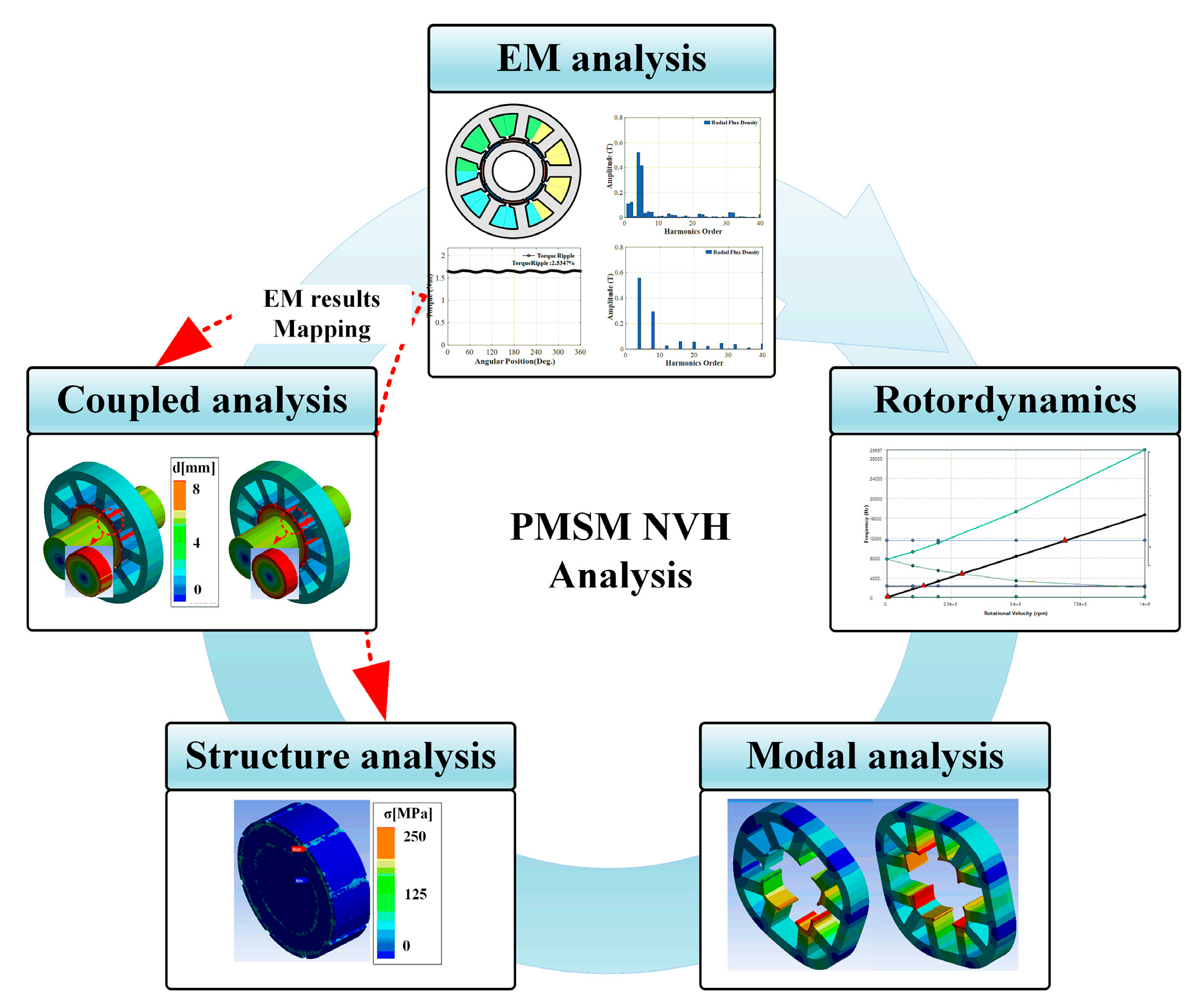
3. Mechanical Analysis
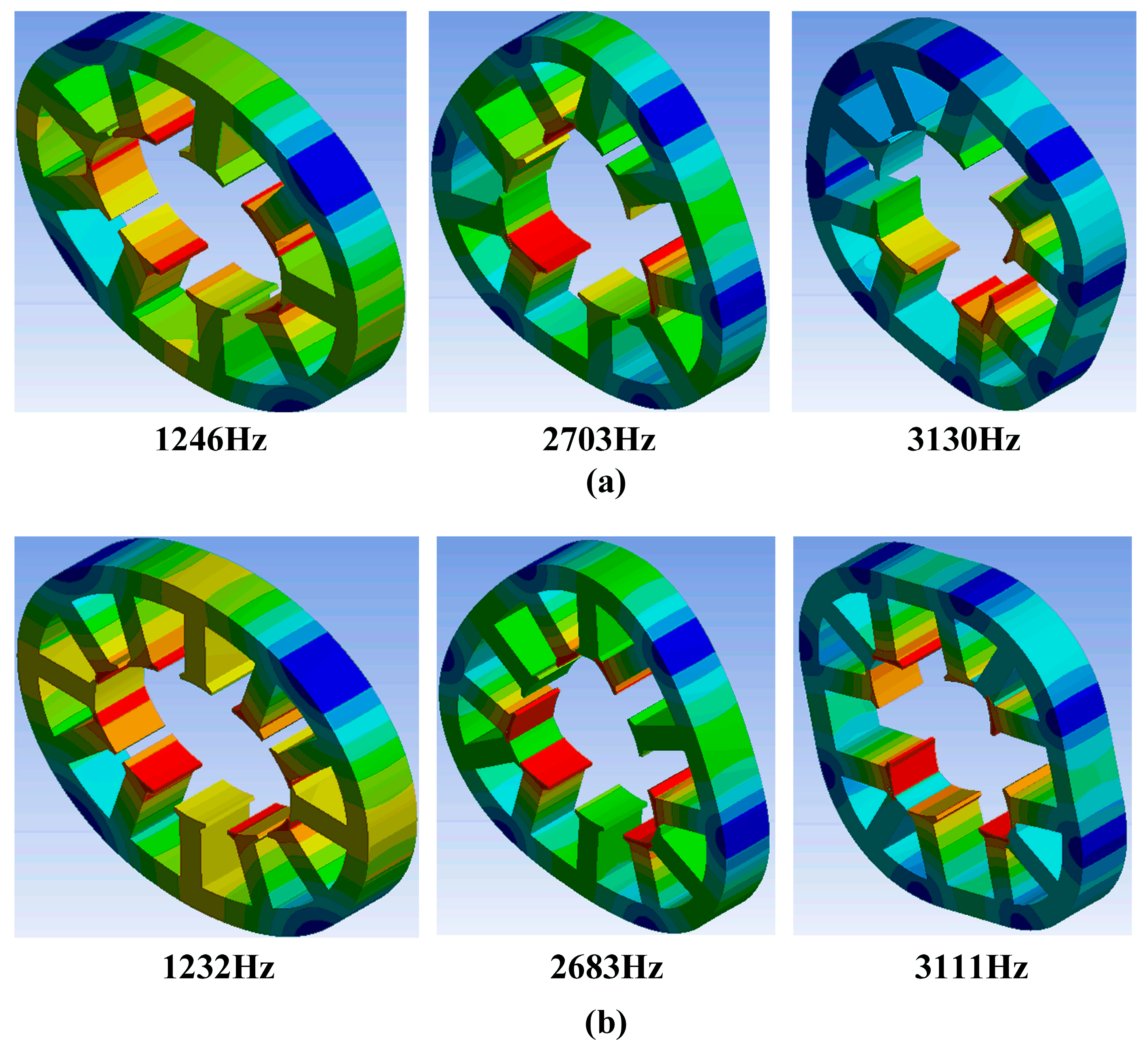
3.1. Modal Analysis
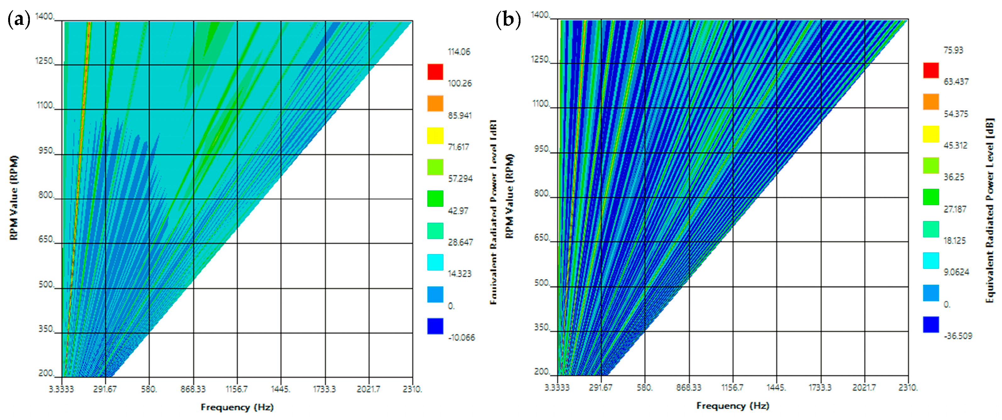
3.2. NVH Analysis
4. Experimental Results
5. Conclusions
Author Contributions
Funding
Conflicts of Interest
References
- Damiano, A.; Floris, A.; Fois, G.; Marongiu, I.; Porru, M.; Serpi, A. Design of a High-Speed Ferrite-Based Brushless DC Machine for Electric Vehicles. IEEE Trans. Ind. Appl. 2017, 53, 4279–4287. [Google Scholar] [CrossRef]
- Dong, J.; Huang, Y.; Jin, L.; Lin, H. Comparative Study of Surface-Mounted and Interior Permanent-Magnet Motors for High-Speed Applications. IEEE Trans. Appl. Supercond. 2016, 26, 1–4. [Google Scholar] [CrossRef]
- Musuroi, S.; Sorandaru, C.; Greconici, M.; Olarescu, V.N.; Weinman, M. Low-cost ferrite permanent magnet assisted synchronous reluctance rotor an alternative for rare earth permanent synchronous motors. Industrial Electronics Society. In Proceedings of the IECON 2013-39th Annual Conference of the IEEE, Vienna, Austria, 10–13 November 2013; pp. 2966–2970. [Google Scholar]
- Dutta, R.; Rahman, M.F.; Chong, L. Winding Inductances of an Interior Permanent Magnet (IPM) Machine with Fractional Slot Concentrated Winding. IEEE Trans. Magn. 2012, 48, 4842–4849. [Google Scholar] [CrossRef]
- Gieras, J.F.; Wang, C.; Lai, J.C. Noise of Poly-Phase Electric Motors, 2nd ed.; Taylor & Francis: New York, NY, USA, 2006. [Google Scholar]
- Zhu, Z.; Liu, Y.; Howe, D. Minimizing the Influence of Cogging Torque on Vibration of PM Brushless Machines by Direct Torque Control. IEEE Trans. Magn. 2006, 42, 3512–3514. [Google Scholar] [CrossRef]
- Zhu, Z.; Howe, D. Influence of design parameters on cogging torque in permanent magnet machines. IEEE Trans. Energy Convers. 2000, 15, 407–412. [Google Scholar] [CrossRef] [Green Version]
- Beccue, P.; Neely, J.; Pekarek, S.; Stutts, D. Measurement and Control of Torque Ripple-Induced Frame Torsional Vibration in a Surface Mount Permanent Magnet Machine. IEEE Trans. Power Electron. 2005, 20, 182–191. [Google Scholar] [CrossRef]
- Zou, J.; Lan, H.; Xu, Y.; Zhao, B. Analysis of Global and Local Force Harmonics and Their Effects on Vibration in Permanent Magnet Synchronous Machines. IEEE Trans. Energy Convers. 2017, 32, 1523–1532. [Google Scholar] [CrossRef]
- Yang, H.; Chen, Y. Influence of Radial Force Harmonics with Low Mode Number on Electromagnetic Vibration of PMSM. IEEE Trans. Energy Convers. 2013, 29, 38–45. [Google Scholar] [CrossRef]
- Wu, L.J.; Zhu, Z.Q.; Chen, J.T.; Xia, Z.P. An Analytical Model of Unbalanced Magnetic Force in Fractional-Slot Surface-Mounted Permanent Magnet Machines. IEEE Trans. Magn. 2010, 46, 2686–2700. [Google Scholar] [CrossRef]
- Zhu, Z.Q.; Jamil, M.L.M.; Wu, L.J. Influence of Slot and Pole Number Combinations on Unbalanced Magnetic Force in PM Machines with Diametrically Asymmetric Windings. IEEE Trans. Ind. Appl. 2013, 49, 19–30. [Google Scholar] [CrossRef]
- Kim, D.-Y.; Park, M.-R.; Sim, J.-H.; Hong, J.-P. Advanced Method of Selecting Number of Poles and Slots for Low-Frequency Vibration Reduction of Traction Motor for Elevator. IEEE/ASME Trans. Mechatron. 2017, 22, 1554–1562. [Google Scholar] [CrossRef]
- Torregrossa, D.; Peyraut, F.; Fahimi, B.; M’Boua, J.; Miraoui, A. Multiphysics Finite-Element Modeling for Vibration and Acoustic Analysis of Permanent Magnet Synchronous Machine. IEEE Trans. Energy Convers. 2010, 26, 490–500. [Google Scholar] [CrossRef]
- Huang, Z.; Fang, J. Multiphysics Design and Optimization of High-Speed Permanent-Magnet Electrical Machines for Air Blower Applications. IEEE Trans. Ind. Electron. 2016, 63, 2766–2774. [Google Scholar] [CrossRef]
- Das, S.; Chowdhury, A.; Paul, S.; Wan, Z.; Islam, R.; Sozer, Y. Experimental and Simulation Based Study of Vibration Prediction in Fractional Slot Permanent Magnet Synchronous Machines. In Proceedings of the 2019 IEEE International Electric Machines & Drives Conference (IEMDC), San Diego, CA, USA, 12–15 May 2019; pp. 1138–1143. [Google Scholar]
- Das, S.; Chowdhury, A.; Wan, Z.; Kouhshahi, M.B.; Pina Ortega, A.; Sozer, Y. Wide Speed Range NVH Performance Optimization in Permanent Magnet Synchronous Machines for Automotive Application Using Vibration Synthesis. In Proceedings of the 2020 IEEE Energy Conversion Congress and Exposition (ECCE), Detroit, MI, USA, 11–15 October 2020; pp. 783–788. [Google Scholar]
- Das, S.; Chowdhury, A.; Wan, Z.; Kouhshahi, M.B.; Pina Ortega, A.; Sozer, Y. Sensitivity Analysis Based NVH Performance Evaluation in Permanent Magnet Synchronous Machines using Lumped Unit Force Response. In Proceedings of the 2020 IEEE Energy Conversion Congress and Exposition (ECCE), Detroit, MI, USA, 11–15 October 2020; pp. 802–807. [Google Scholar]


| Parameter | 9 Slot | 12 Slot | Harmonics Order |
|---|---|---|---|
| Back-EMF THD | 20.10% | 16.77% | 1,3,5 |
| Cogging torque | 1.53 mNm | 311.53 mNm | 6 |
| Torque ripple | 2.53% | 34.80% | 6 |
| No-load UMF | 8.85 N | 0.01 N | 8 |
| On-load UMF | 72.42 N | 0.08 N | 8 |
| Deformations | 2.5 um | 0.04 um | 1,3,4,6,7,8 |
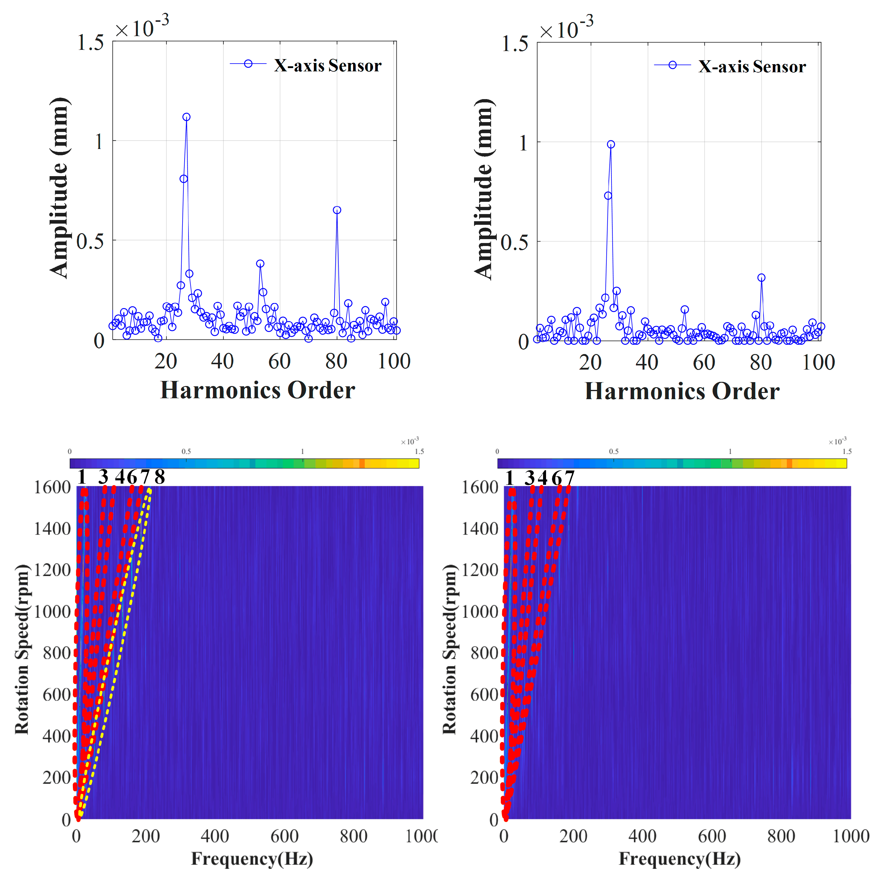
| Main harmonics | 1,3,4,6,7,8 | 1,3,4,6,7 | - |
| Parameter | 9-Slot | 12-Slot | ||
|---|---|---|---|---|
| Classification | FEA | Experiment | FEA | Experiment |
| Deformations | 1.6 um | 2.5 um | 1.3 um | 0.04 um |
| Main Harmonics | 1,3,4,6,7,8 | 1,3,4,6,7,8 | 1,3,4,6,7 | 1,3,4,6,7 |
Publisher’s Note: MDPI stays neutral with regard to jurisdictional claims in published maps and institutional affiliations. |
© 2020 by the authors. Licensee MDPI, Basel, Switzerland. This article is an open access article distributed under the terms and conditions of the Creative Commons Attribution (CC BY) license (http://creativecommons.org/licenses/by/4.0/).
Share and Cite
Bang, T.-K.; Shin, K.-H.; Lee, J.-I.; Lee, H.-K.; Cho, H.-W.; Choi, J.-Y. Experimental and Comparative Study of Rotor Vibrations of Permanent Magnet Machines with Two Different Fractional Pole/Slot Combinations. Appl. Sci. 2020, 10, 8792. https://doi.org/10.3390/app10248792
Bang T-K, Shin K-H, Lee J-I, Lee H-K, Cho H-W, Choi J-Y. Experimental and Comparative Study of Rotor Vibrations of Permanent Magnet Machines with Two Different Fractional Pole/Slot Combinations. Applied Sciences. 2020; 10(24):8792. https://doi.org/10.3390/app10248792
Chicago/Turabian StyleBang, Tae-Kyoung, Kyung-Hun Shin, Jeong-In Lee, Hoon-Ki Lee, Han-Wook Cho, and Jang-Young Choi. 2020. "Experimental and Comparative Study of Rotor Vibrations of Permanent Magnet Machines with Two Different Fractional Pole/Slot Combinations" Applied Sciences 10, no. 24: 8792. https://doi.org/10.3390/app10248792