Electromagnetic Characteristic Analysis of Permanent Magnet Synchronous Machine Considering Current Waveform According to Static Rotor Eccentricity


Abstract
:1. Introduction
2. PMSM Control
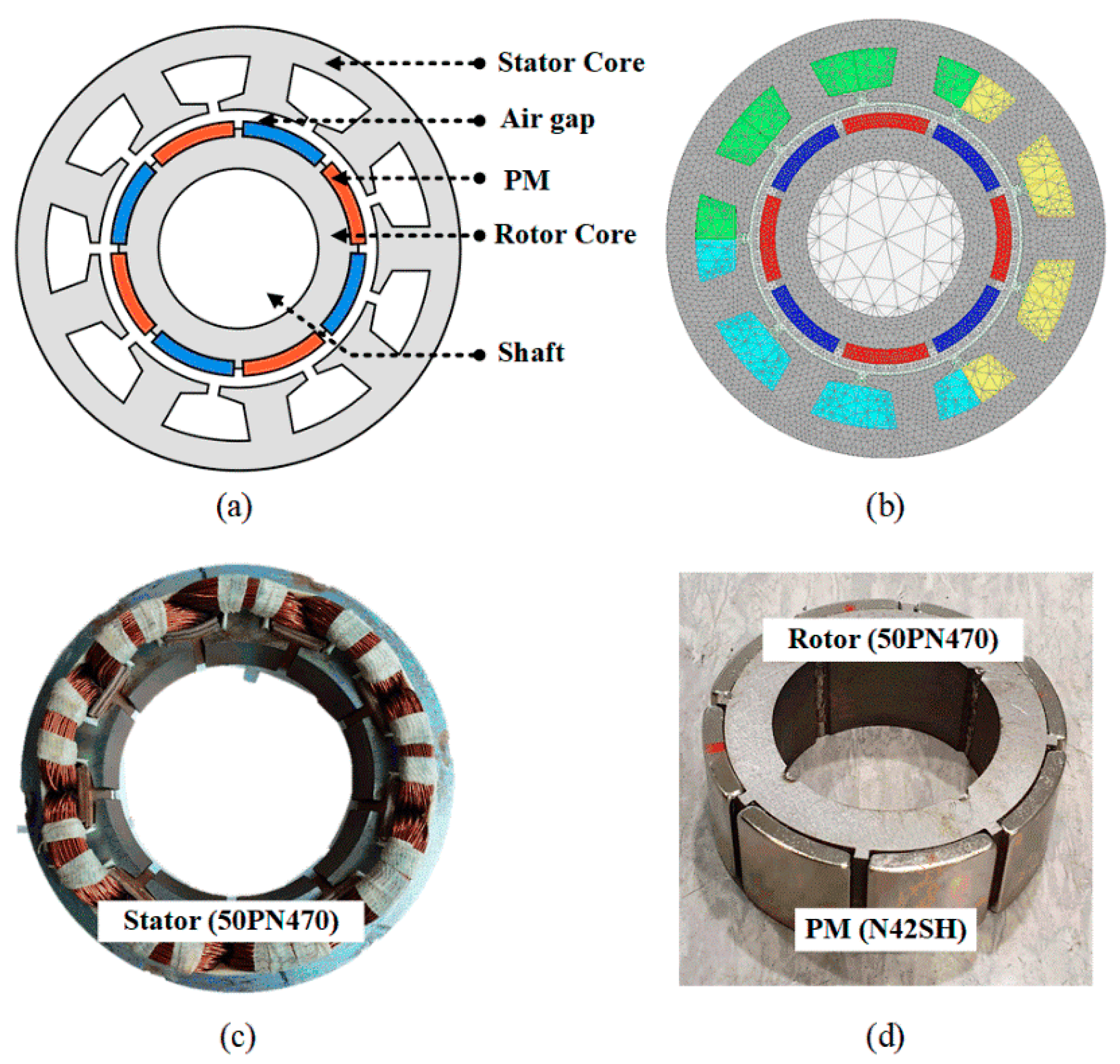
2.1. Analysis Model
2.2. Mathematical Modelling of PMSM
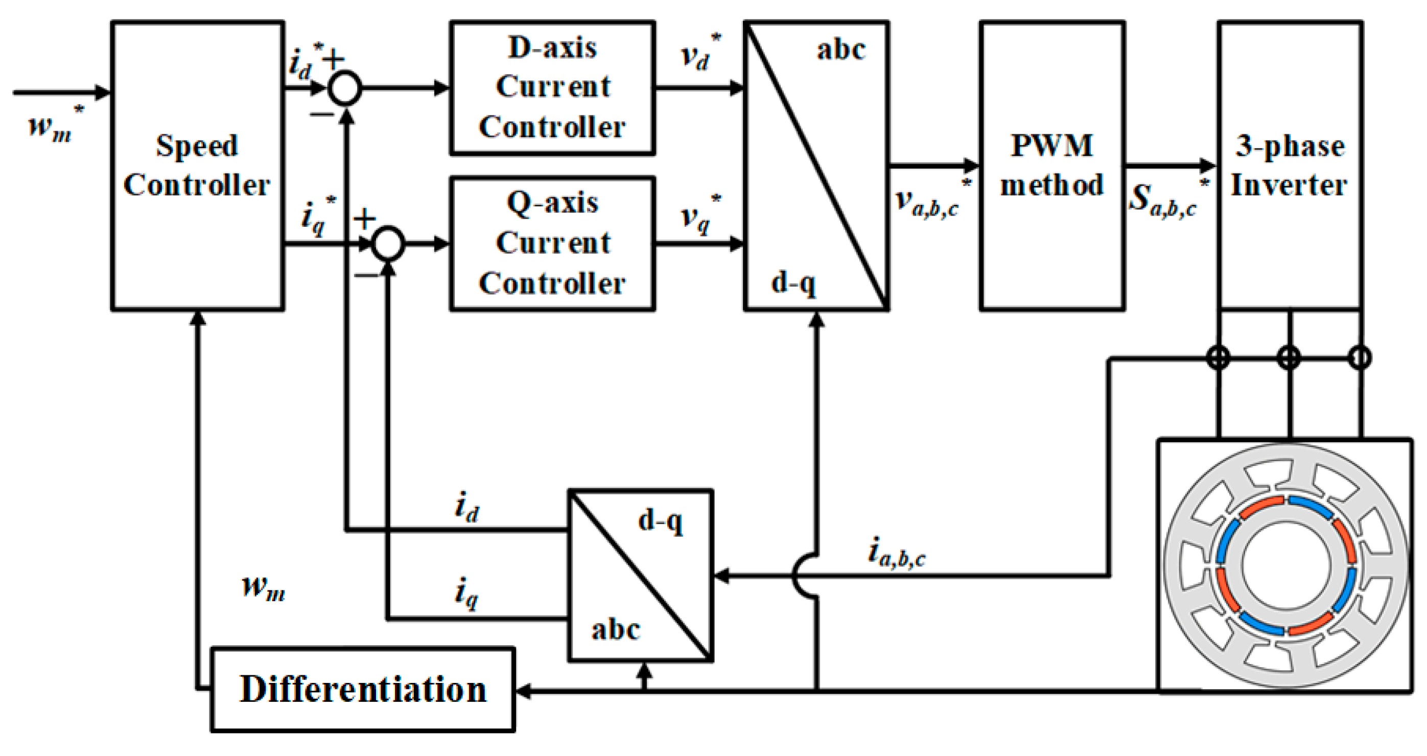
2.3. Vector Control of PMSM
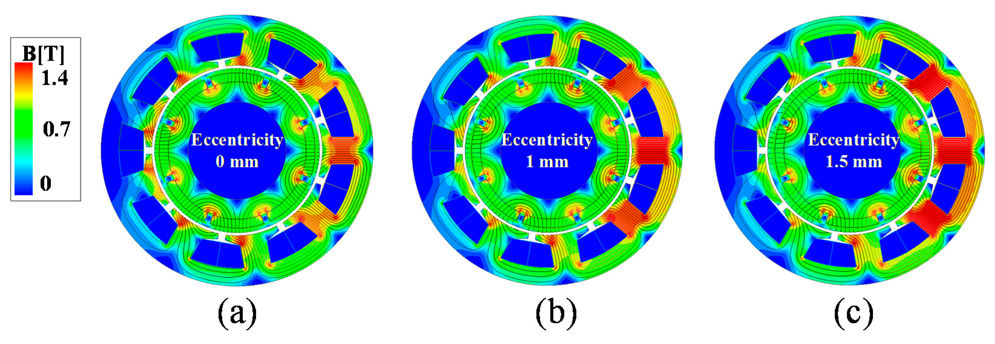
3. Dynamic Analysis of PMSM Based on Rotor Eccentricity
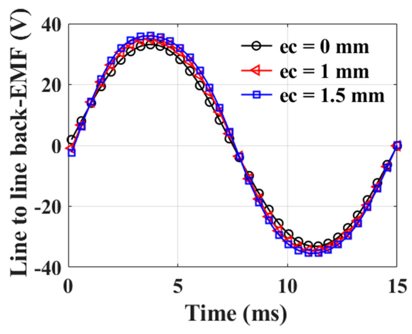
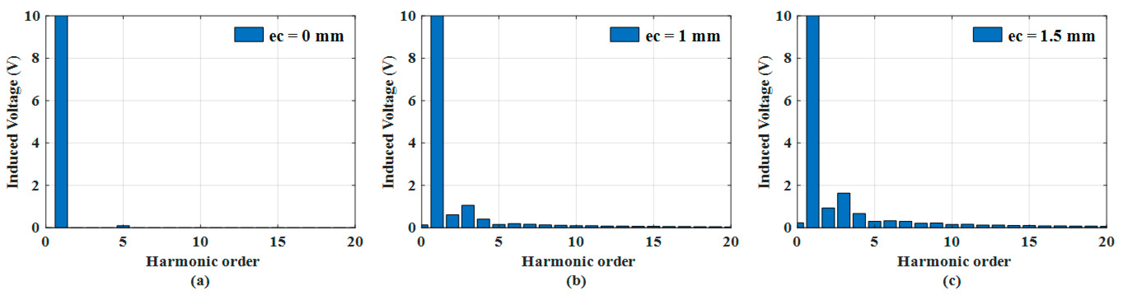
3.1. No-Load Analysis
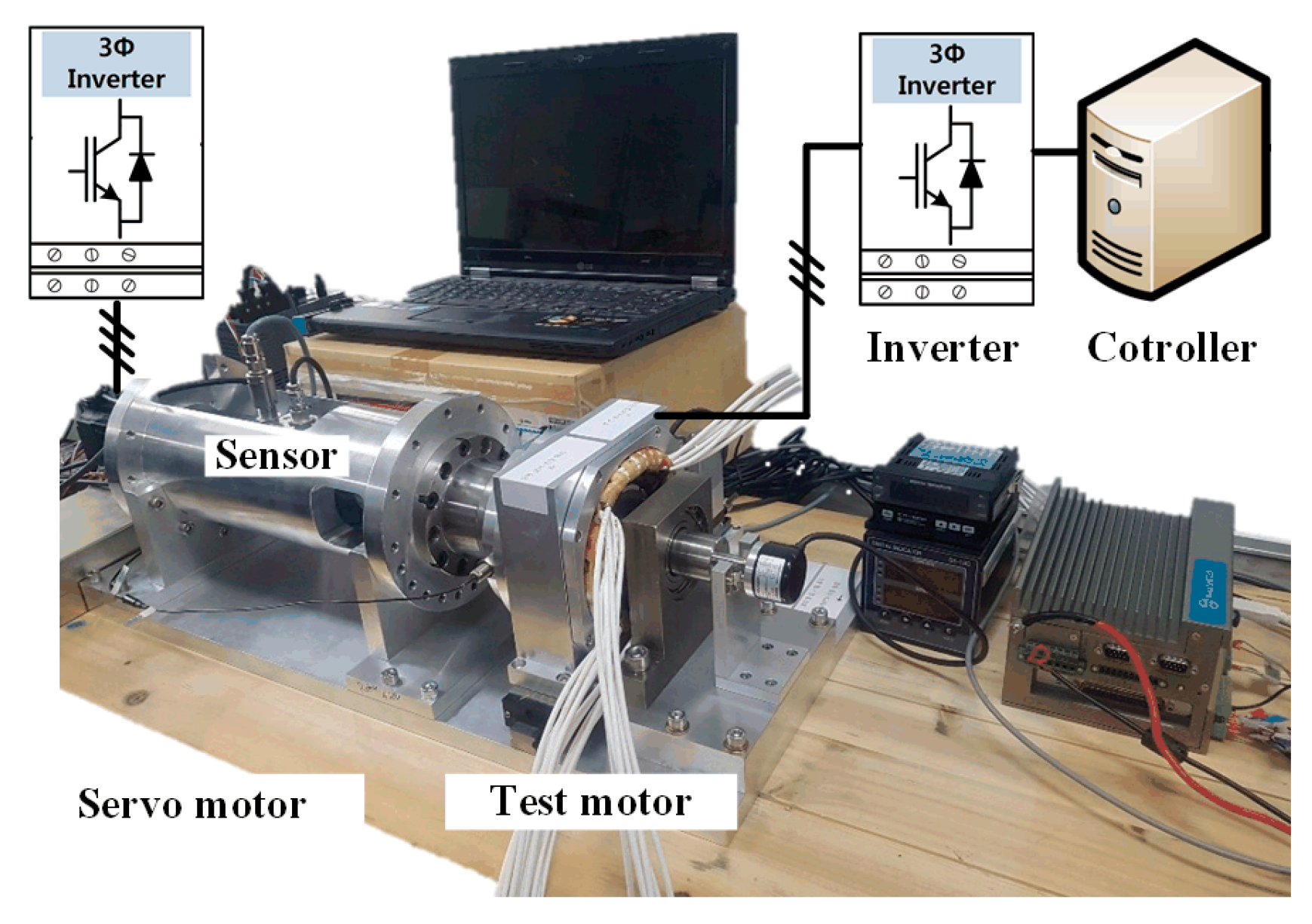
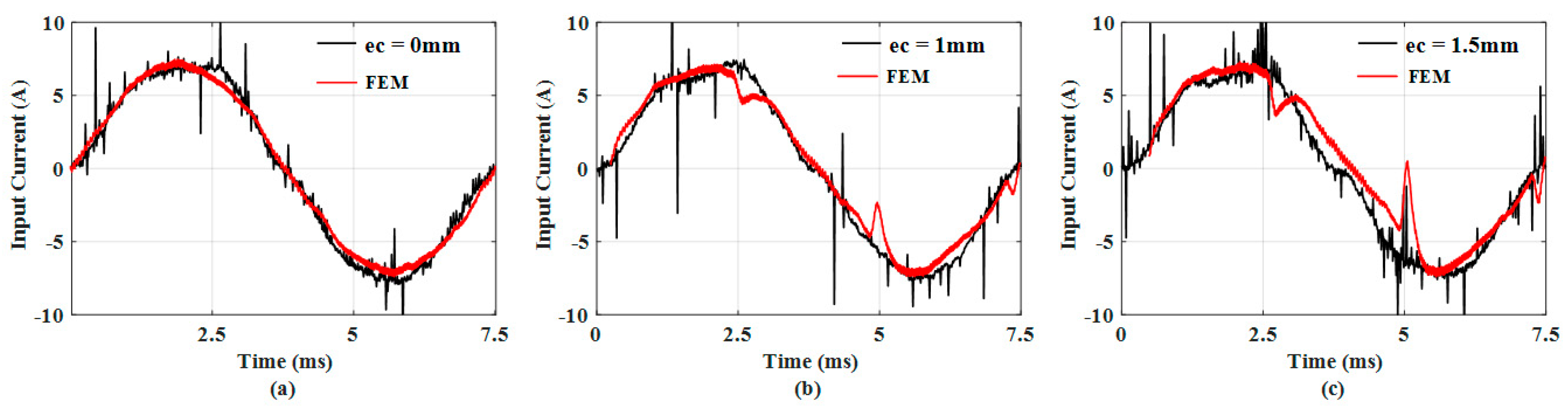
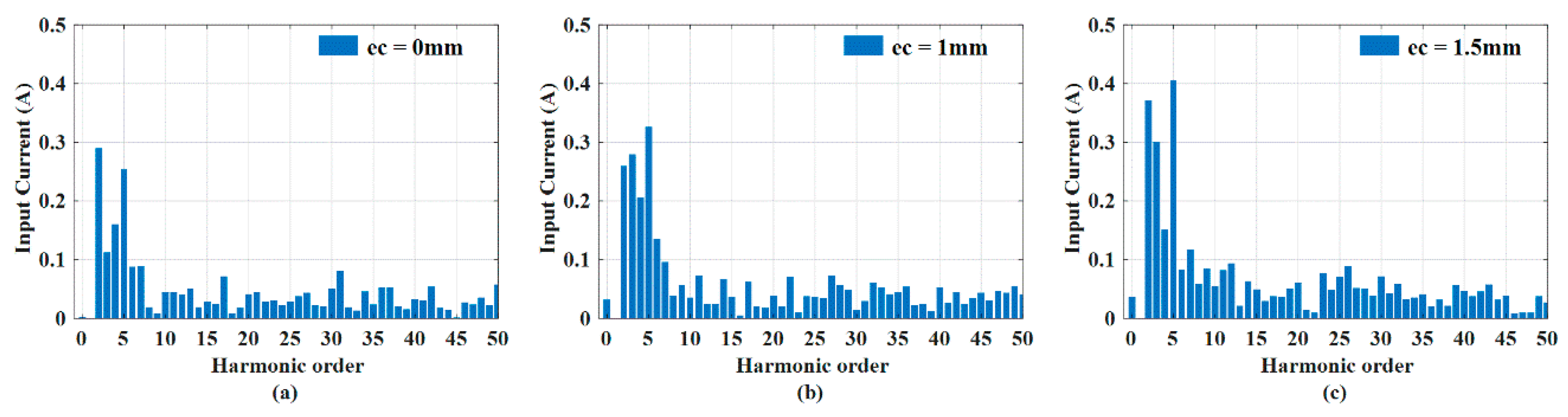
3.2. Co-Simulation Analysis
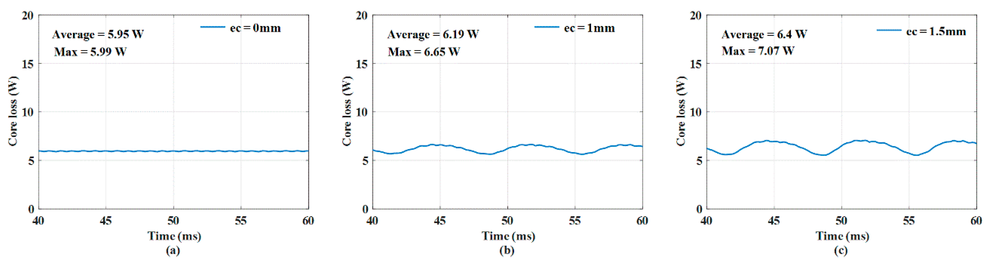
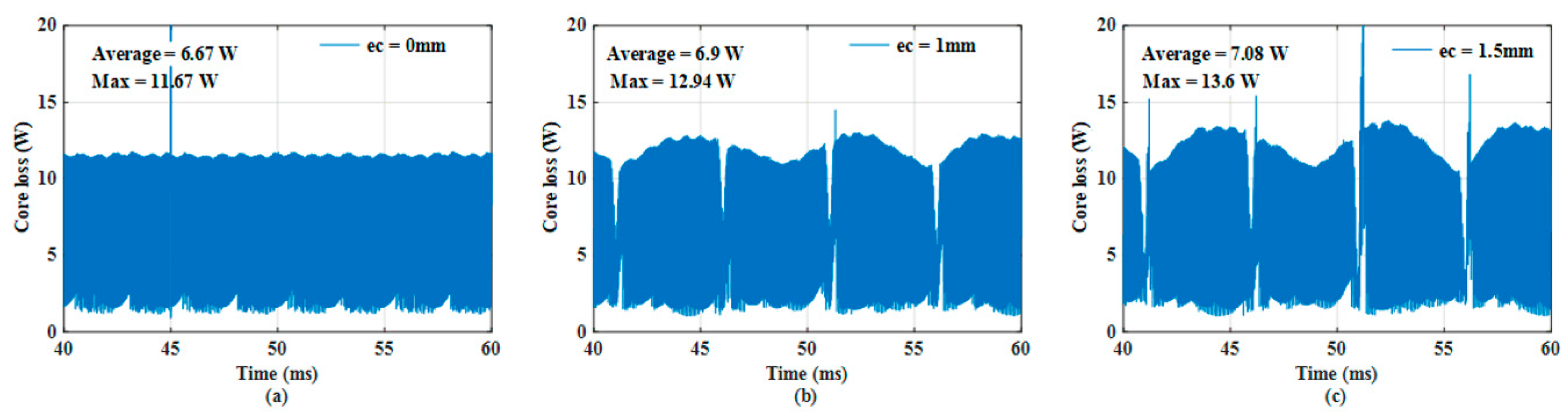
3.3. Core Loss Analysis
4. Results and Discussion
5. Conclusions
Author Contributions
Funding
Conflicts of Interest
References
- Choi, J.-Y.; Park, Y.-S.; Jang, S.-M. Experimental Verification and Electromagnetic Analysis for Performance of Interior PM Motor According to Slot/Pole Number Combination. IEEE Trans. Magn. 2012, 48, 987–990. [Google Scholar] [CrossRef]
- Goktas, T.; Zafarani, M.; Lee, K.W.; Akin, B.; Sculley, T. Comprehensive Analysis of Magnet Defect Fault Monitoring Through Leakage Flux. IEEE Trans. Magn. 2017, 53, 1–10. [Google Scholar] [CrossRef]
- Prieto, M.D.; Espinosa, A.G.; Ruiz, J.R.; Urresty, J.C.; Ortega, J.A. Feature extraction of demagnetization faults in PMSMs based on box-counting fractal dimension. IEEE Trans. Ind. Electron. 2011, 58, 1594–1605. [Google Scholar] [CrossRef]
- Park, Y.; Fernandez, D.; Lee, S.B.; Hyun, D.; Jeong, M.; Kommuri, S.K.; Cho, C.; Reigosa, D.; Briz, F. On-line detection of rotor eccentricity for PMSMs based on Hall-effect field sensor measurements. In Proceedings of the 2017 IEEE Energy Conversion Congress and Exposition (ECCE), Cincinnati, OH, USA, 1–5 October 2017; pp. 4678–4685. [Google Scholar]
- Thomson, W.; Barbour, A. On-line current monitoring and application of a finite element method to predict the level of static airgap eccentricity in three-phase induction motors. IEEE Trans. Energy Convers. 1998, 13, 347–357. [Google Scholar] [CrossRef]
- Hyun, D.; Hong, J.; Bin Lee, S.; Kim, K.; Wiedenbrug, E.J.; Teska, M.; Nandi, S.; Chelvan, I.T. Automated Monitoring of Airgap Eccentricity for Inverter-Fed Induction Motors Under Standstill Conditions. IEEE Trans. Ind. Appl. 2011, 47, 1257–1266. [Google Scholar] [CrossRef]
- Amirat, Y.; Benbouzid, M.E.H.; Bensaker, B.; Wamkeue, R. Condition monitoring and fault diagnosis in wind energy conversion systems: A review. In Proceedings of the IEEE PEMDC Conference, Antalya, Turkey, 3–5 May 2007. [Google Scholar]
- Lu, B.; Li, Y.; Wu, X.; Yang, Z. A review of recent advances in wind turbine condition monitoring and fault diagnosis. In Proceedings of the IEEE Conference on Power Electronics and Machines in Wind Applications (PEMWA), Lincoln, NE, UISA, 24–26 June 2009; No. 24026. pp. 1–7. [Google Scholar]
- Yang, W.; Tavner, P.J.; Wilkinson, M. Wind Turbine Condition Monitoring and Fault Diagnosis Using Both Mechanical and Electrical Signatures. In Proceedings of the 2008 IEEE/ASME International Conference on Advanced Intelligent Mechatronics, Xi’an, China, 2–5 July 2008; pp. 1296–1301. [Google Scholar] [CrossRef]
- Hanselman, D. Brushless Motors: Magnetic Design, Performance and Control of Brushless DC and Permanent Magnet Synchronous Motors; EMan Press LLC: Houston, TX, USA, 2012. [Google Scholar]
- Soong, W.; Miller, T.J.E. Field-weakening performance of brushless synchronous AC motor drives. IEE Proc. Electr. Power Appl. 1994, 141, 331–340. [Google Scholar] [CrossRef]
- Soong, W.; Ertugrul, N. Field-weakening performance of interior permanent-magnet motors. IEEE Trans. Ind. Appl. 2002, 38, 1251–1258. [Google Scholar] [CrossRef] [Green Version]
- Han, C.; Choi, J.-Y.; Ahn, J.-H.; Choi, J.-H.; Jang, S.-M. The harmonics influence and efficiency improvement in high-speed permanent magnet synchronous motor using 2-D finite element method. In Proceedings of the IEEE InterMag Conference, Vancouver, BC, Canada, 7–11 May 2012. [Google Scholar]


| Parameter | Value | Unit |
|---|---|---|
| Number of slots/poles | 9/8 | |
| Outer radius of stator | 47 | mm |
| Outer radius of rotor | 43 | mm |
| Thickness of PM | 5 | mm |
| Axial length | 30 | mm |
| Magnet remanence | 1.27 | T |
| Pole arc ratio | 0.9 | |
| Rated speed | 1000 | rpm |
| Rated torque | 2 | N |
| Rated power | 200 | W |
| PWM method | SPWM |
| Harmonic Order | ec = 0 mm (V) | ec = 1 mm (V) | ec = 1.5 mm (V) |
|---|---|---|---|
| 0 | 0 | 0.13 | 0.23 |
| 1 | 33.2 | 35.9 | 37.4 |
| 2 | 0 | 0.6 | 0.9 |
| 3 | 0 | 1.05 | 1.6 |
| 4 | 0 | 0.4 | 0.7 |
| 5 | 0.1 | 0.16 | 0.3 |
| 6 | 0 | 0.2 | 0.3 |
| 7 | 0 | 0.16 | 0.3 |
| 8 | 0 | 0.13 | 0.2 |
| f (Hz) | Kh (w/m3) | Ke (w/m3) | Ka (w/m3) | nst |
|---|---|---|---|---|
| 50 | 199.9 | 0.67 | 0 | 2 |
| 60 | 195 | 0.77 | 0 | 2 |
| 100 | 181.1 | 0.12 | 7.8 | 2 |
| 200 | 182.4 | 0.5 | 4.4 | 2 |
| 400 | 199.9 | 0.67 | 0 | 2 |
Publisher’s Note: MDPI stays neutral with regard to jurisdictional claims in published maps and institutional affiliations. |
© 2020 by the authors. Licensee MDPI, Basel, Switzerland. This article is an open access article distributed under the terms and conditions of the Creative Commons Attribution (CC BY) license (http://creativecommons.org/licenses/by/4.0/).
Share and Cite
Lee, H.K.; Bang, T.K.; Woo, J.H.; Shin, H.S.; Choi, J.Y. Electromagnetic Characteristic Analysis of Permanent Magnet Synchronous Machine Considering Current Waveform According to Static Rotor Eccentricity. Appl. Sci. 2020, 10, 8453. https://doi.org/10.3390/app10238453
Lee HK, Bang TK, Woo JH, Shin HS, Choi JY. Electromagnetic Characteristic Analysis of Permanent Magnet Synchronous Machine Considering Current Waveform According to Static Rotor Eccentricity. Applied Sciences. 2020; 10(23):8453. https://doi.org/10.3390/app10238453
Chicago/Turabian StyleLee, Hoon Ki, Tae Kyoung Bang, Jong Hyeon Woo, Hyo Seob Shin, and Jang Young Choi. 2020. "Electromagnetic Characteristic Analysis of Permanent Magnet Synchronous Machine Considering Current Waveform According to Static Rotor Eccentricity" Applied Sciences 10, no. 23: 8453. https://doi.org/10.3390/app10238453