Review

A Review of Modular Multilevel Converters for Stationary Applications

1
ETEC Department & MOBI Research Center, Vrije Universiteit Brussel (VUB), Pleinlaan 2, 1050 Brussels, Belgium
2
MOBI CoreLab, Flanders Make, 3001 Heverlee, Belgium
3
Department of Electrical Engineering, Istanbul Technical University, Istanbul 34469, Turkey
4
Department of Electrical and Electronics Engineering, Istanbul Okan University, Istanbul 34959, Turkey
*
Author to whom correspondence should be addressed.
Appl. Sci. 2020, 10(21), 7719; https://doi.org/10.3390/app10217719
Submission received: 9 October 2020 / Revised: 26 October 2020 / Accepted: 29 October 2020 / Published: 31 October 2020
(This article belongs to the Special Issue Power Electronic Applications in Power and Energy Systems)

Abstract

:
A modular multilevel converter (MMC) is an advanced voltage source converter applicable to a wide range of medium and high-voltage applications. It has competitive advantages such as quality output performance, high modularity, simple scalability, and low voltage and current rating demand for the power switches. Remarkable studies have been carried out regarding its topology, control, and operation. The main purpose of this review is to present the current state of the art of the MMC technology and to offer a better understanding of its operation and control for stationary applications. In this study, the MMC configuration is presented regarding its conventional and advanced submodule (SM) and overall topologies. The mathematical modeling, output voltage, and current control under different grid conditions, submodule balancing control, circulating current control, and modulation methods are discussed to provide the state of the MMC technology. The challenges linked to the MMC are associated with submodule balancing control, circulating current control, control complexity, and transient performance. Advanced nonlinear and predictable control strategies are expected to improve the MMC control and performance in comparison with conventional control methods. Finally, the power losses associated with the advanced wide bandgap (WBG) power devices (such as SiC, GaN) are explored by using different modulation schemes and switching frequencies. The results indicate that although the phase-shifted carrier-based pulse width modulation (PSC-PWM) has higher power losses, it outputs a better quality voltage with lower total harmonic distortion (THD) in comparison with phase-disposition pulse width modulation (PD-PWM) and sampled average modulation pulse width modulation (SAM-PWM). In addition, WBG switches such as silicon carbide (SiC) and gallium nitride (GaN) devices have lower power losses and higher efficiency, especially at high switching frequency in the MMC applications.

1. Introduction

The modular multilevel converter (MMC), as a recently developed member of the multilevel converter family, was first proposed by Lesnicar and Marquardt in 2002 [1]. In 2010, this innovative converter was first commercially used by Siemens in San Francisco’s Trans bay project [2]. Since its first introduction, the MMC has gained considerable attention and development owing to its promising advantages such as excellent output performance, high modularity, simple scalability, and low voltage and current rating demand for the power switches [3,4]. These are clear advantages for the MMC over the traditional two-level and multilevel converters [5]. The MMC is particularly applicable to a wide range of medium and high-voltage power conversion systems, such as high-voltage direct current (HVDC) transmission systems [6,7,8], medium voltage motor drives [9,10,11,12], renewable energy systems [13,14,15], battery energy storage systems (BESS) [16,17,18], static synchronous compensator (STATCOM) [19,20], (hybrid) electrical vehicle chargers and drivers [21,22,23,24], and power interfacing applications [25,26].
The main purpose of this review paper is to present the current state of the art of the MMC technology and offer a better understanding of its operation and control. In this context, a detailed review is conducted associated with the main research issues regarding circuit topologies, mathematical modeling, control schemes, and modulation methods. The MMC circuit configuration is reviewed comprehensively from the perspective of the submodule and overall topologies. Despite limited DC fault tolerance [27,28], the half-bridge submodule (HBSM) is much preferred commercially among a variety of two-level and multilevel topologies considering its simple configuration and low cost. Advanced overall topologies are reported over the past years to meet application-oriented requirements. The MMC control methods are developed and reported with respect to the output voltage and current regulation [29], submodule balancing [30], and circulating current elimination [31] or injection [32]. Meanwhile, nonlinear and predictive controls [33] provide a solution to improve the MMC dynamic response instead of using a conventional proportional integral (PI) regulator or resonant controller. The modulation techniques of the power converter [34] directly affect the output value and output quality on power semiconductors. Numerous studies have been carried out to improve the modulation methods and are considered in this review. The emerging WBG technology [35] leads to a revolution in power electronics, which is prospected with power losses estimation using different modulation techniques in the MMC application.
The remainder of this paper is organized as follows. Section 2 introduces a variety of conventional and advanced submodule (SM) topologies together with overall architectures depending on the phase structure and arm connection mode. This is followed by an investigation of the MMC mathematical modeling and control strategies in Section 3, including output voltage and current control, submodule balancing control, circulating current control, and nonlinear and predictive control. Several MMC multilevel modulation techniques are presented in Section 4. Section 5 reviews and prospects the incorporation of advanced WBG technology together with power losses evaluation with various PWM modulation methods. Finally, the concluding remarks are drawn in Section 6.

2. MMC Topologies

2.1. Submodule Topologies

The generalized configuration of a three-phase MMC is comprised of a DC terminal, an AC terminal, and a converting kernel involving three phase legs, as shown in Figure 1. Each leg/phase has two symmetric arms referred to as the upper arm and lower arm. The upper arm and lower arm contain a group of identical submodules connected in series together with a chock inductor to suppress high-frequency components in the arm current. An MMC can achieve bidirectional power conversion.

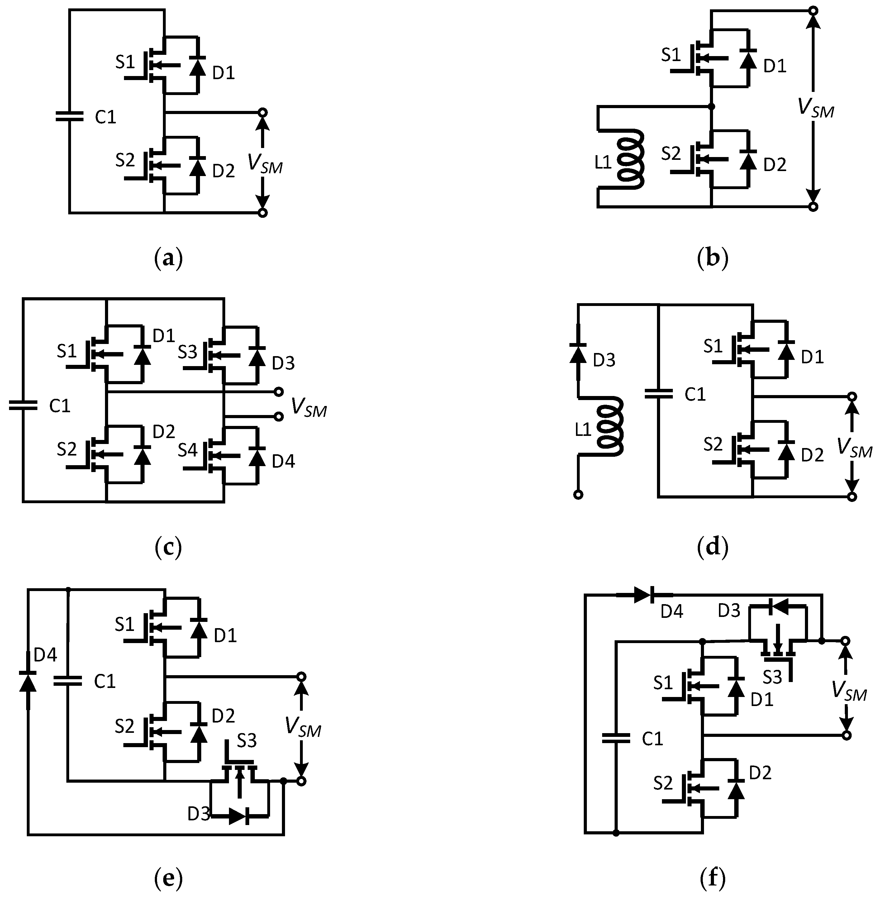
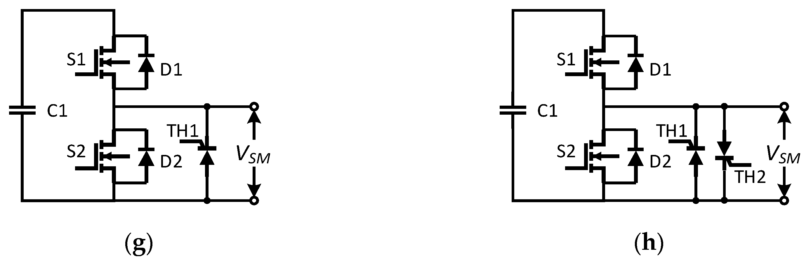
2.1.1. Two-Level Submodule Topologies

The SM is the fundamental component of an MMC. During the past two decades, researchers have proposed a range of submodule topologies. According to the output voltage level, these submodules can be classified into two categories: two-level submodule topologies with a single source and multilevel submodule topologies with multiple sources.
Among all the SM topologies, the half-bridge submodule (HBSM) [1] is the most popular configuration thanks to its simple structure together with a low system cost. The HBSM is comprised of two power switches with anti-parallel diodes and a floating capacitor, as shown in Figure 2a. The submodule voltage can be switched to zero or capacitor voltage v c 1 , depending on whether the capacitor is bypassed or inserted. Thus, the HBSM is also named as the chopper SM. One apparent disadvantage of an HBSM is its vulnerability to DC fault current.
Currently, power converters are in majority voltage source converters (VSC), while current source converters (CSC) are less common. In terms of submodule for current source MMCs, an inductor replaces the capacitor in the HBSM [36], and the anti-parallel diodes are connected in series with the switching devices (Figure 2b). The output current is either zero ( L 1 bypassed) or the inductor current ( L 1 inserted).
Another well-known SM topology for MMC is a full-bridge structure (FBSM) [37]. An FBSM has two half-bridge legs with one floating capacitor. Each leg includes two switches with anti-parallel diodes. Its configuration is shown in Figure 2c. The output voltages can be zero, v c , and v c , which enables FBSMs to counter DC failure current. To reduce the cost of power devices, some studies [38,39] proposed unidirectional topologies in which certain IGBT(s) are substituted by a diode(s).
A kind of self-balancing submodule (SBSM) is introduced in [40,41]. It is composed of the HBSM with an inductor and one diode (Figure 2d). It can self-balance unipolar voltage due to the clamped diode D3. This topology allows the submodule to balance capacitor voltage automatically (without voltage balancing algorithm).
To enhance the DC fault blocking capability of the HBSM, a clamp-single submodule (CSSM) [42] is proposed to suppress failure current. A clamp-single cell is also named a unipolar full-bridge SM self-blocking SM. A CSSM has two types of configurations (Figure 2e,f) composed of a half-bride module connected with a transistor and a diode. During normal operation, S3 is always conducting. When a DC fault is detected, all transistors are set to off to block the short-circuit current.
Another concept to tackle the vulnerability of the HBSM during DC fault is to introduce thyristors to the half-bridge cell. For instance, the study in [27] proposes a single-thyristor HBSM and double-thyristor HBSM where thyristor(s) are connected in the terminal shown in Figure 2g,h, respectively. The thyristors are always turned off during normal operation and are triggered to force the current to flow through it once the DC short failure is monitored. The double-thyristor structure has an advantage compared to the single-thyristor cell in terms of bidirectional current. It is cost-effective compared to other topologies with a DC blocking function such as FBSM, since there are no extra switching power losses during normal operation.

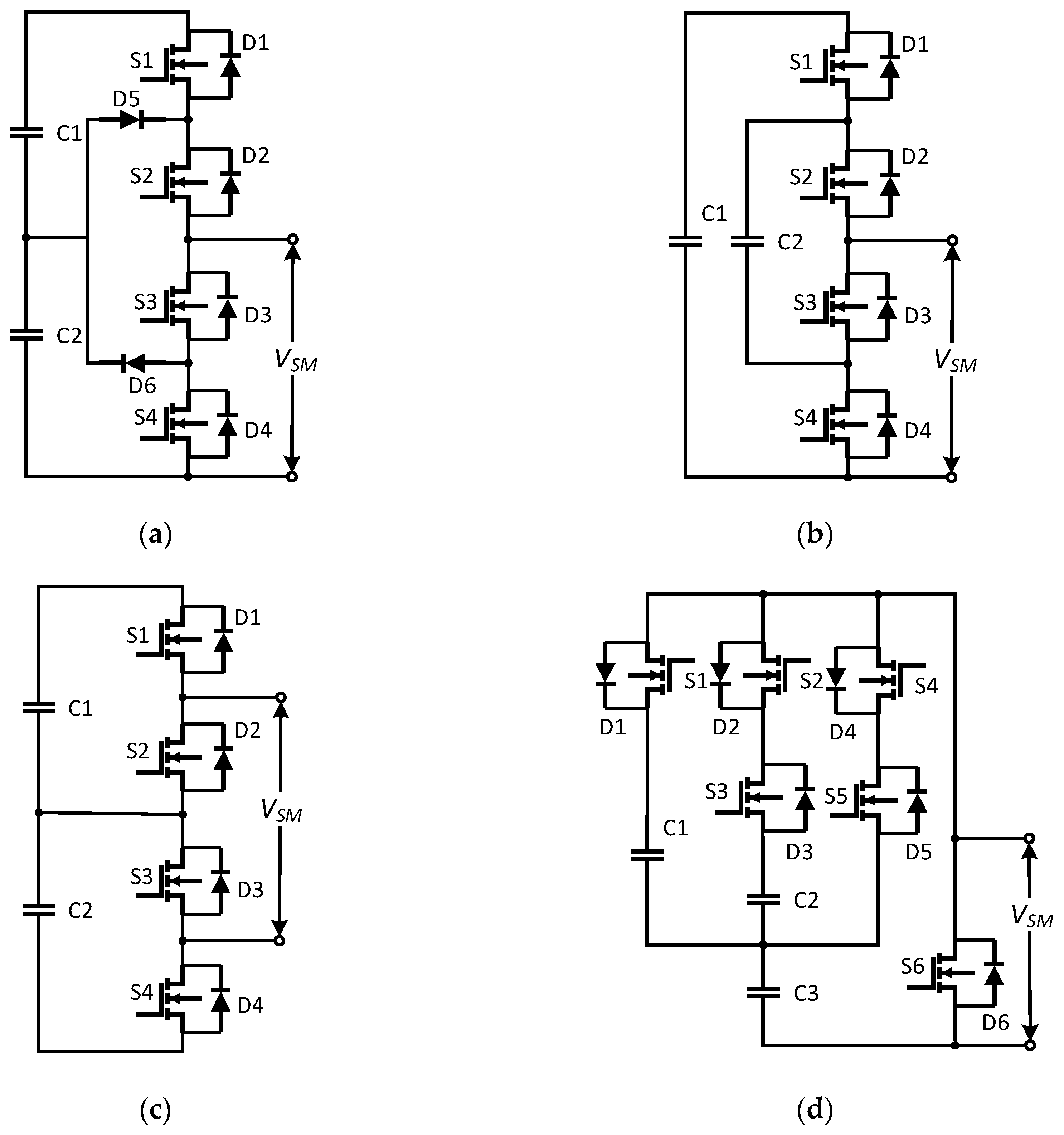
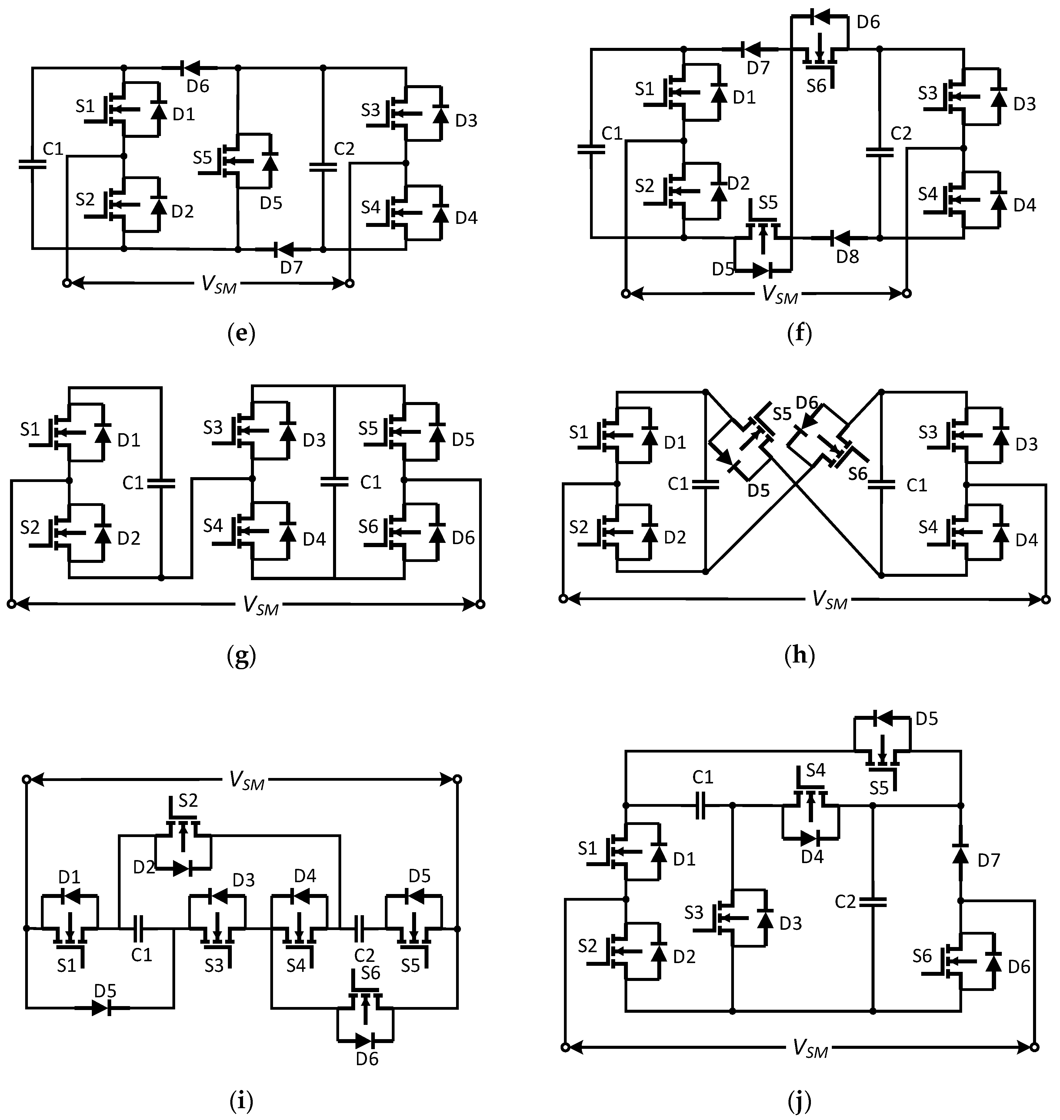
2.1.2. Multilevel Submodule Topologies

Neutral point clamped (NPC) and flying capacitor (FC) concepts are classical multilevel converter topologies. They were also introduced as three-level submodules in MMCs. The circuit configurations of the NPC submodule (NPCSM) and FC submodule (FCSM) [43,44] are presented in Figure 3a,b, respectively. NPCSM contains four IGBT devices with anti-parallel diodes, two clamping diodes, and two capacitors. FCSM includes similar components except for the clamping diodes. Both of them can generate three voltage levels: v c 1 + v c 2 , v c 2 , zero for NPCSM, and v c 1 , v c 1 v c 2 or v c 2 , zero for FCSM.
The cascaded half-bridge submodule (CHBSM) [45] is another configuration that outputs three voltage states: v c 1 + v c 2 , v c 1 or v c 2 , and zero. It is composed of two series-connected half-bridge cells, as drawn in Figure 3c.
With respect to submodule weight and size, the storage capacitor has a large influence. To reduce its volume, a compact submodule topology [46] was proposed with a stacked switched capacitor (SSC) energy buffer, as shown in Figure 3d. The SSC energy buffer refers to C1, C2, C3, and S3 along with S5. C3 is the main voltage source. C1 and C2 act as active supporting capacitors to compensate C3 voltage. Compared with HBSM, the total volume of SSCSM capacitors can be decreased by 40% at least.
A clamp-double submodule (CDSM) [47] (Figure 3e) consists of two identical HBSMs connected by two extra diodes and an IGBT, which is always on during normal operation. A clamp-double cell can generate a three-level voltage: v c 1 + v c 2 , v c 1 / v c 2 , and zero. In the case of DC fault, all the power devices are set off to resist the DC short-circuit current. A CDSM has only half utilization of the capacitor voltages ( v c 1 or v c 2 ) in blocking mode. Therefore, using one extra IGBT is advised to be involved in the CDSM [48] (Figure 3f) to output 2 v c 1 as blocking voltage. One apparent weakness of a CDSM is the increased power losses, since all the switches work during normal operation.
Hybrid submodules (HSM) are generally based on the HBSM, as their primary purpose is to enable it to withstand DC fault with less components [49,50]. As shown in Figure 3g, a hybrid cell is comprised of series-connected HBSM and FBSM. It is tolerant of DC failure with three quarters of semiconductors compared with involving FBSMs alone. Similarly, [51] proposes a mixed submodule based on HBSM and CDSM. It is suggested to achieve fast DC fault current clearing and capacitor uniform distribution at the cost of adding an extra diode between the submodules.
Figure 3h shows a cross-connected submodule (CCSM) [52] that consists of two HBSMs connected back to back via two IGBTs with anti-parallel diodes. The CCSM can output five symmetric voltage levels: ± ( v c 1 + v c 2 ) , ± v c 1 / ± v c 2 , and zero. This topology is tolerant of DC fault current by turning off crossed IGBTs S5 and S6. Crossed IGBTs conduct alternately during normal operation, which increases power losses.
The researchers proposed a new switched capacitor submodule (SCSM) [53], as shown in Figure 3i. It is composed of two capacitors and six IGBTs with anti-parallel diodes. The two capacitors are connected in series to output a voltage 2 v c , whereas they are connected in parallel to output a voltage v c , which enables SCSM to achieve voltage balancing with only half of the voltage sensors utilized in the other submodules. The SCSM is able to ride through a DC-link short circuit by turning off all the IGBTs.
A composite three-level submodule (CSM) was designed in [54] containing two capacitors, six power switches, and one diode, as presented in Figure 3j. The main feature of a CSM is that it offers alternative DC fault blocking solutions including all-blocked, partly blocked, or staged blocking. All IGBTs are set off in blocked mode to avoid over-current. In partly blocked mode, S3 and S5 are switched on to connect C1 and C2 in parallel, which balance the capacitor voltages effectively. Staged blocking is the combination of all-blocked and partly blocked. With DC fault blocking schemes, especially the latter two, a CSM is capable of addressing DC fault current together with capacitor unbalanced charging.
A comparative summary of the aforementioned submodule topologies is presented in Table 1 [25,55,56]. The comparison shows the performances of different submodule configurations associated with the number of sources and switching devices, output voltage levels, bipolar operation, DC fault blocking capability, power losses and cost, together with control complexity. The HBSM, due to its simple construction, has the lowest power losses and cost, which are related to the count of devices. However, it is not able to deal with bidirectional power flow and is sensitive to DC short failure. Other topologies, e.g., FBSM, CDSM, or HSM, have a bipolar operation and DC fault blocking capability at a price of increasing structural complexity. It is desired to carry out a submodule construction that is capable of bipolar operation, short circuit blocking, as well as symmetrical voltage levels at a minimum cost. The main challenge for the optimal submodule blocking topology is to make a tradeoff between the construction complexity and its performances.

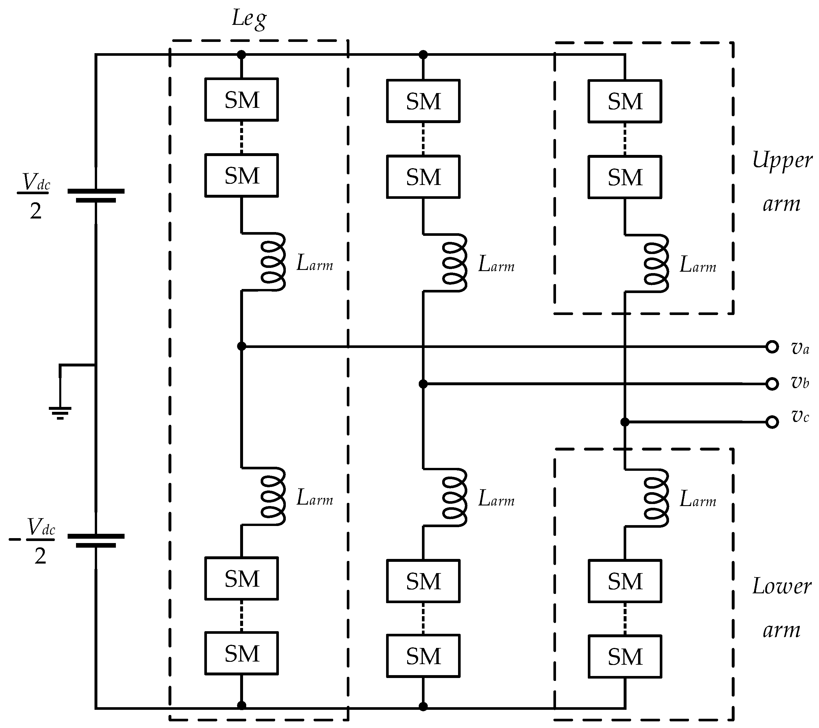
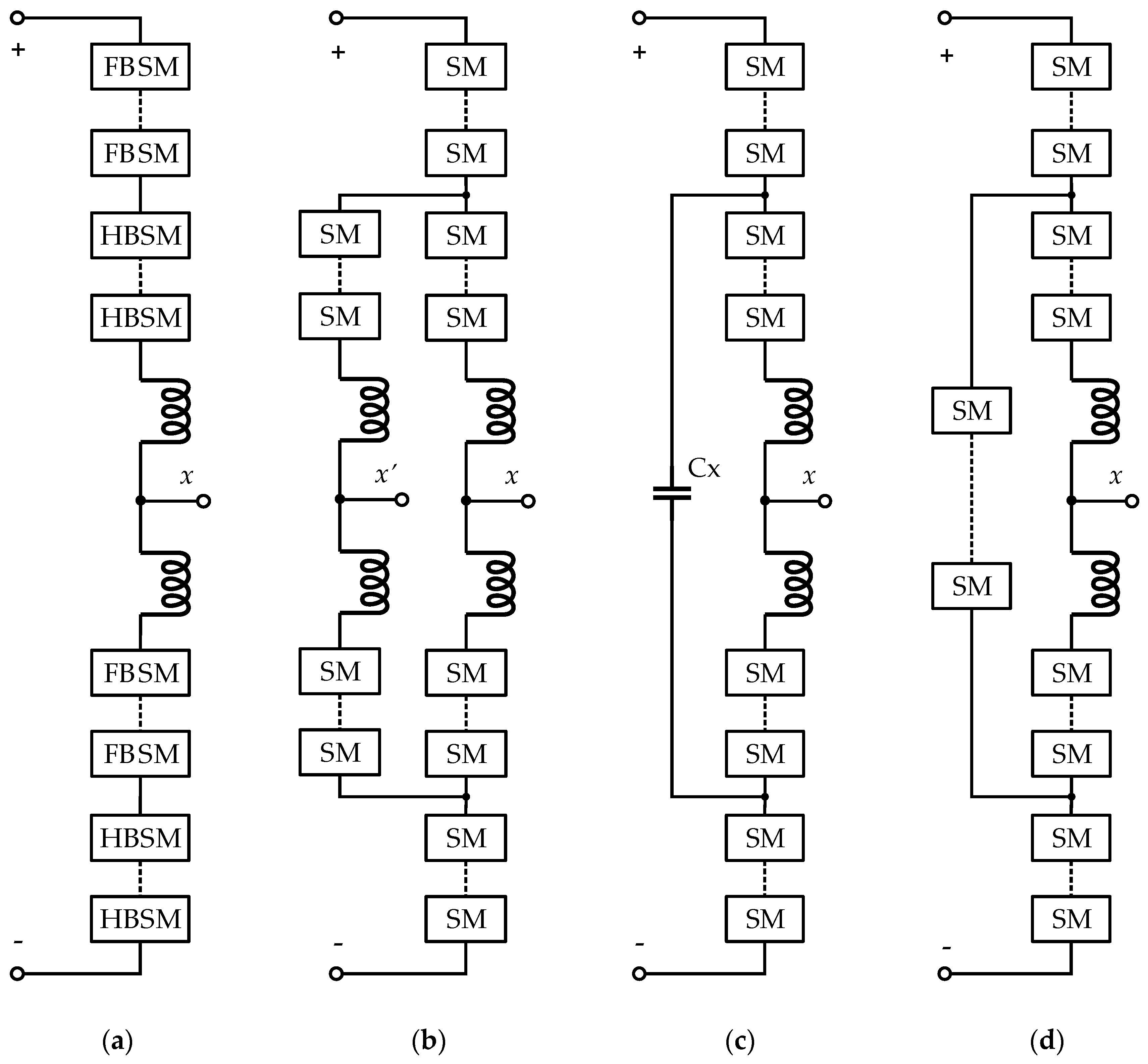
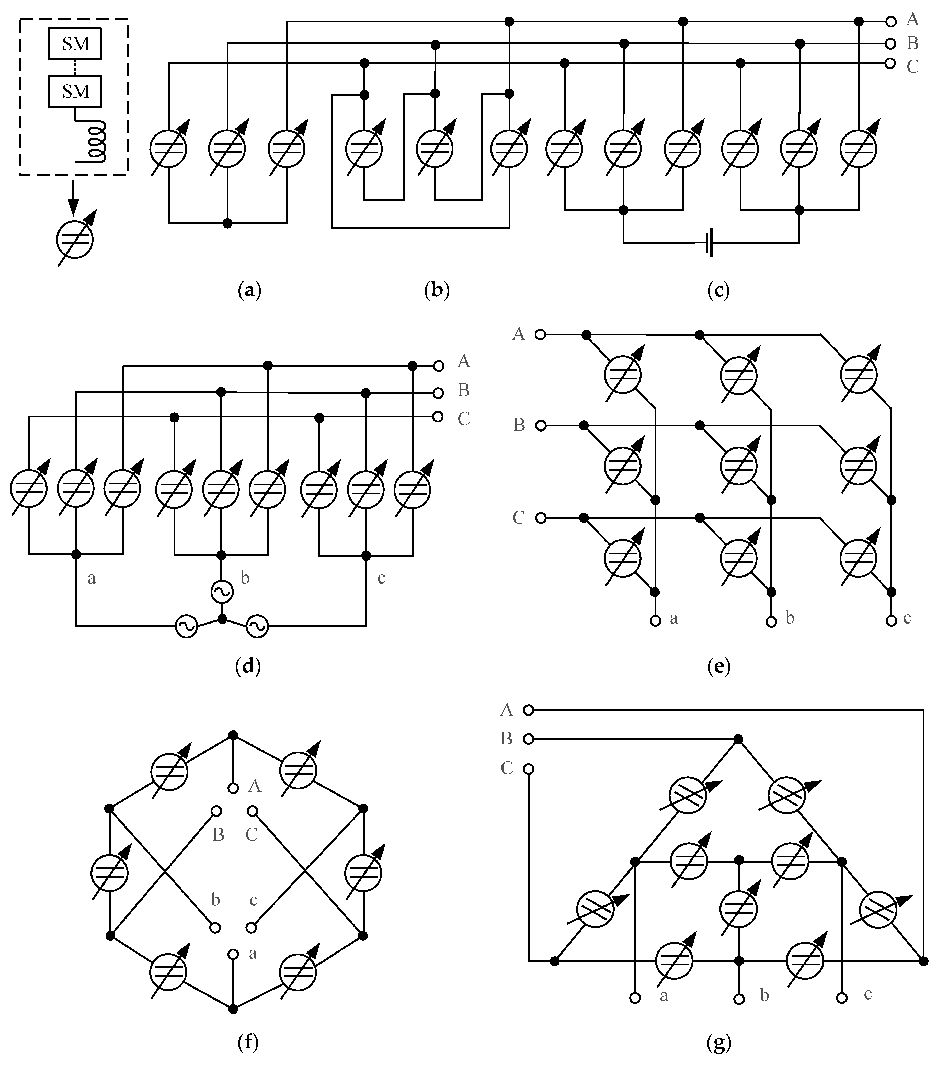
2.2. Overall Topologies

In terms of MMC overall topologies, the phase-leg or arm structure is one of the research points to improve the performance of MMCs. The hybrid arm/leg architecture is a key factor to trade off the system cost, power losses, and DC fault blocking capacity. Hybrid MMCs usually contain two different submodules. A symmetric hybrid MMC in [57] is based on HBSMs and FBSMs. The single-phase structure is demonstrated in Figure 4a. Each arm is composed of an identical number of HBSMs and FBSMs. Likewise, an asymmetric hybrid MMC is discussed in [58], where HBSMs and FBSMs are separated in the upper and lower arms. Simulation and experimental results indicate that the asymmetric hybrid MMC is more advantageous to regulate DC bus voltage smoothly with well-controlled submodule capacitor voltages. Similarly to the former symmetric hybrid MMC, a hybrid MMC referred to as MCH-MMC is investigated in [59] and is composed of both HBSMs and CDSMs. The authors develop a repetitive predictive control strategy to suppress the circulating current and balance the submodule capacitor voltage for the proposed MCH-MMC.
A new family of MMC referred to as bifurcate MMCs is investigated in [60,61,62]. Figure 4b shows the single-phase circuit configuration including two single-bifurcate arms. Each arm consists of three branches, and two branches are connected to different phases of the AC port. The single-bifurcate arm can deduce the multi-bifurcate arm with a multi-layer of submodules. Control schemes are given for single- and multi-bifurcate structures. Theoretical analysis and simulation results indicate that bifurcate MMCs are suitable for low-modulation-ratio applications.
Du et al. propose a passive cross-connected MMC (PC-MMC) [10] and an active cross-connected MMC (AC-MMC) [11] whose single-phase configurations are shown in Figure 4c,d, respectively. The PC-MMC is also referred to as the flying-capacitor MMC. PC-MMC and AC-MMC have similar circuit configurations. The difference is that the flying capacitor in the PC-MMC is replaced by a series of additional submodules in the AC-MMC. Control strategies are also proposed by Du et al. in [10,11]. For the PC-MMC, the flying capacitor is capable of balancing power between upper and lower arms, suppressing voltage ripples on submodule capacitors at low/zero frequency operation. This is achieved by active controlled submodules in terms of AC-MMC. Both PC-MMC and AC-MMC are applicable in medium-voltage motor drive.
Apart from PC-MMC and AC-MMC, Du et al. also contribute to a star-channel MMC (SC-MMC) [63] and a delta-channel MMC (DC-MMC) [64] together with control schemes. Each arm of the SC-MMC and DC-MMC is divided into two parts, which are interconnected by additional submodules in either star or delta configuration. The upper and lower arms are usually composed of HBSMs for cost-saving and power efficiency matters, and the star-channel or delta-channel branches are realized by FBSMs to regulate the bidirectional current. Both SC-MMC and DC-MMC are capable of operating at zero/low-fundamental frequency with minimized submodule capacitor voltage ripples.
According to the connection schemes of the MMC arms, the overall architectures can be classified as star-configured MMCs and delta-configured MMCs [65,66]. These two types are classified as either chopper cells or bridge cells on account of the selection of submodules. They can be further split into single-star, single-delta, double-star, double-delta, and triple-star based on star and delta count. The configuration circuits are shown in Figure 5.
Single-star and single-delta are the basic structures in the subfamily of star/delta-configured MMCs. They have three strings of submodules connected in either star or delta configuration. A single-star MMC is preferred in applications such as power compensators (STATCOM) and battery energy storage systems. Double-star and double-delta include two-star or delta-configured clusters connected by a DC source/load. They can realize the bidirectional current conversion of DC-AC or AC-DC. A double-star is widely used in MMC industries such as HVDC transmission and motor drive systems. A triple-star MMC [67] is comprised of three star-connected clusters, i.e., nine branches. It is well-known as a “modular multilevel matrix converter” (M3C) [68,69,70]. Figure 4d,e are the two same presentations for triple-star MMC or M3C. It is capable of converting AC to AC directly between the bidirectional three-phase power system confronted with traditional AC-DC-AC indirect conversion, which is similar to back-to-back configuration [71] and involves two three-phase MMCs including twelve branches. It has superior performance for the medium-voltage and high-power motor drive system with regenerative braking.
In recent years, researchers developed a new topology for MMC referred to hexagonal MMC or Hexverter [72]. The Hexverter consists of six arms connected in a hexagonal circuit, and each arm is alternatively connected to one phase of two three-phase AC networks, as shown in Figure 5f. This novel topology can achieve direct AC-AC conversion with a further reduced number of branches and components when compared with triple-star MMC or M3C. This converter is advantageous when applied in applications such as low-frequency wind turbines.
However, the Hexverter has limited reactive power provision capability at some operation points, together with injected common-mode voltage, which is not expected in some applications such as motor drives. Therefore, another hexagonal topology called Hex-Y [73,74] is proposed based on the Hexverter. Except for the retaining hexagon circuit, three star-connected branches are added within the hexagon, as shown in Figure 5g. A comparison for low-frequency mode was carried out between the Hex-Y and the M3C due to their identical number of branches. Simulation results indicate that the Hex-Y has a lower peak and RMS currents for low frequency below 5 Hz, and beyond 5 Hz, these turn to be higher than the M3C. The Hex-Y has flat torque-speed characteristics with low frequency. It is applicable for both fields which operate at low frequency and require full power capability in a wide frequency spectrum.

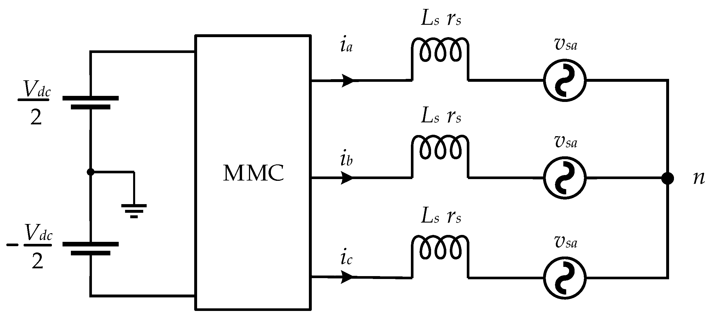
3. Mathematical Modeling and Control of Three-Phase MMC

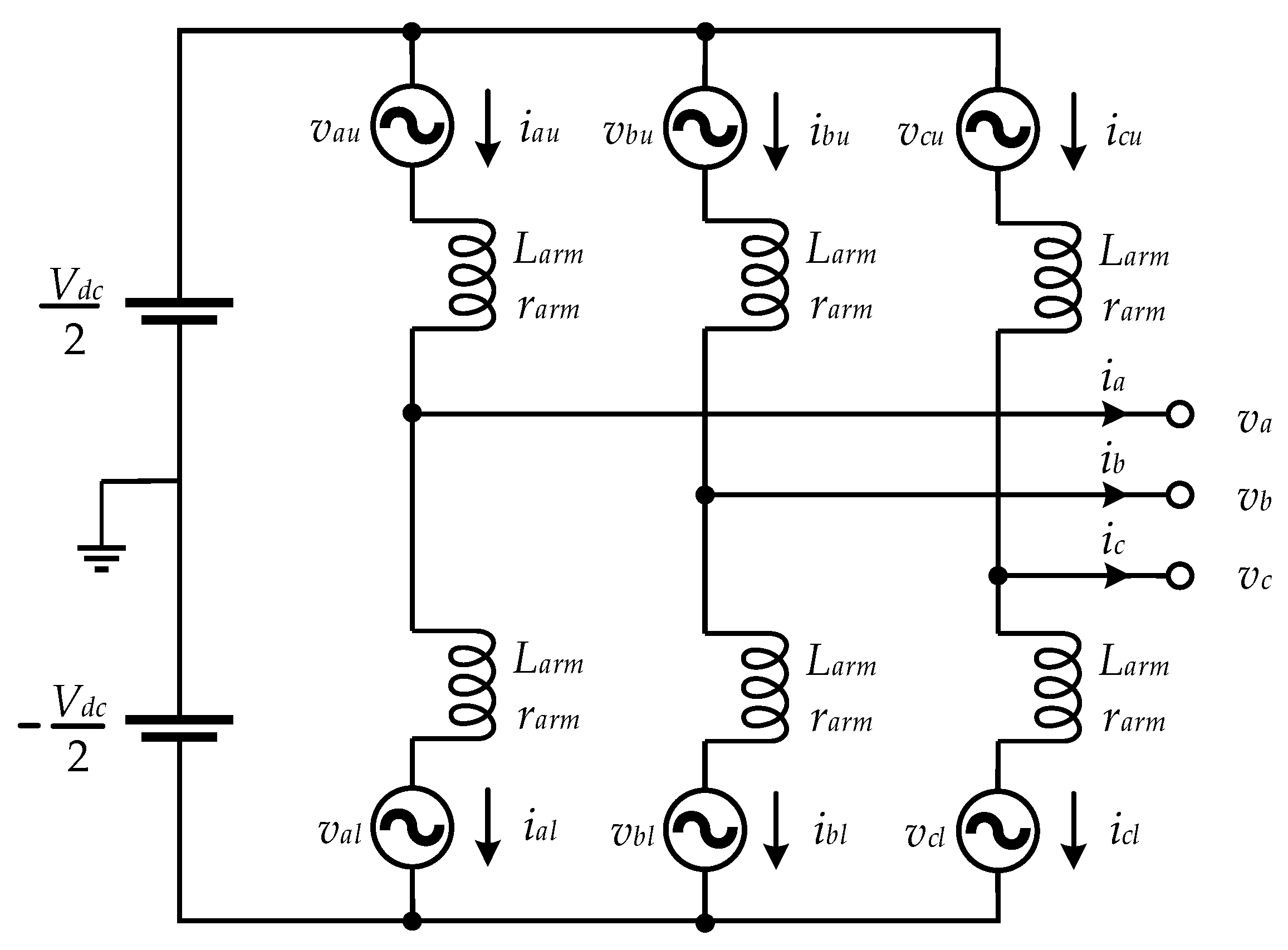
3.1. Mathematical Modeling

Assuming that the arm and leg structures of three-phase MMC are perfectly symmetrical, the mathematical model [3,55,75,76,77,78] can be established based on a widely accepted equivalent circuit depicted in Figure 6.
The equivalent AC electromotive force (EMF) is symmetrical in the upper and lower arm, resulting in equally distributed output AC current in the arms. The upper and lower currents can be expressed by
i x u = i x 2 + i c i r x
i x l = i x 2 + i c i r x
where i x u and i x l represent the upper and lower currents of phase x   ( x = a , b , c ) , i c i r x is the circulating current in each phase, and i x represents the phase-x output AC current. From Equations (1) and (2), the output and circulating currents can be deduced as:
i x = i x u i x l
i c i r x = i x u + i x l 2
The circulating current contains DC and harmonic components. Due to the three-phase symmetrical structure, the equivalent DC EMF is equal for each leg, leading to an evenly distributed direct current in each phase. Thus, the DC component of the circulating current can be expressed by
i c i r x u _ d c = i c i r x l _ d c = i c i r x _ d c = i d c 3
where i c i r x u _ d c , i c i r x l _ d c , and i c i r x u _ d c are the DC components of cirrulating currents in the upper/lower arm and phase-x. The DC component of circulating currents is naturally eliminated when the DC link voltage is not practically employed such as operating in the motor drive mode in the battery-based MMC. In this case, the circulating currents consist of only harmonic components.
According to Kirchoff’s voltage law, the upper and lower voltages can be given by
v x u = V d c 2 v x L a r m d i x u d t r a r m i x u
v x l = V d c 2 + v x L a r m d i x l d t r a r m i x l
where v x u and v x l are the upper and lower voltages of phase x , v x is the output voltage, L a r m and r a r m give the inductance and resistance of the arm inductor, and V D C is the DC-link voltage. By separately adding and subtracting Equations (6) and (7), and using the relationship in Equations (1) and (2), the outer and inner dynamic equations of MMC can be expressed as
L a r m 2 d i x d t = r a r m 2 i x + v x l v x u 2
L a r m d i c i r x d t = r a r m i c i r x r a r m 3 i d c + V d c 2 v x u + v x l 2
According to Equations (8) and (9), the output current i x can be regulated by adjusting the voltage difference between the upper arm and the lower arm, and the circulating current i c i r x can be controlled by changing the sum of the upper arm and the lower arm voltages. These two driving voltages of the output current and circulating current can be defined as
v x = v x l v x u 2
v c i r x = V d c v x u v x l 2
In addition, the dynamic equations of the submodule capacitor voltages are given by
C S M d v S M u k d t = i x u S S M u k
C S M d v S M l k d t = i x l S S M l k
where C S M is the capacitor capacitance, v S M u k and v S M l k are the submodule voltages in the upper and lower arms, and S S M u k and S S M l k represent the submodule gating signals, respectively. When S S M k =1, the submodule is inserted, and the charging or discharging is realized according to the direction of current. When S S M k = 0, the submodule is bypassed, and the capacitor voltage remains the same.
Equations (8), (9), (12), and (13) provide a generalized dynamic model of the MMC. The specific dynamic modeling principle can be based on the perspective of either voltage-based control or energy-based control [79]. When the submodule capacitors are substituted by batteries as the energy source, the state of charge (SoC) management turns to the key factor correspondingly [80,81]. Researchers have contributed a range of approaches for SoC estimation, where the most popular SoC tracking method is the Coulomb counting method [82] given by:
S o C ( t ) = S o C ( 0 ) 0 t i ( t ) d t 3600 Q max × 100 %
where Q m a x is the battery maximum capacity. The relationships between battery current, capacity, and SoC are given by [18,80,83]
i u x k = Q max d S o C u x k d t
i l x k = Q max d S o C l x k d t
where i u x k and i l x k are the battery current, and S o C x k and S o C l k donate individual SoC at the upper and lower arm. The average SoC of each phase arm is defined as
S o C ¯ u x = 1 N k = 1 N S o C x k
S o C ¯ l x = 1 N k = 1 N S o C l k
where S o C ¯ u x and S o C ¯ l x represent the average SoC of the upper arm and lower arm. Assuming the switching losses are neglected, the input and output power at the AC side and DC side of the submodule are equal.
P u x k = V b a t i u x k = v u x k i u x
P l x k = V b a t i l x k = v l x k i l x
where P u x k and P L x k represent the individual power in the upper and lower arm, and V b a t is the battery voltage. The arm power is the sum of total submodules given by
P u x = i u x k = 1 N v u x k = ( Q max k = 1 N d S o C u x k d t ) V b a t
P l x = i l x k = 1 N v l x k = ( Q max k = 1 N d S o C l x k d t ) V b a t
where P u x and P L x represent the upper and lower arm power. According to Equations (17) and (18) and using the representation in Equations (21) and (22), the sum and difference of arm power ( P and P Δ ) are yielded,
P = P u x + P u x = N V b a t Q max d ( S o C ¯ u x + S o C ¯ l x ) d t = v x i x + N V b a t i c i r x L a r m ( i u x d i u x d t + i l x d i l x d t )
P Δ = P u x P u x = N V b a t Q max d ( S o C ¯ u x S o C ¯ l x ) d t = N 2 V b a t i x 2 v x i c i r x L a r m d i x i c i r x d t
Neglecting the alternating term, the upper equation can be simplified as [83]:
N V b a t d ( S o C ¯ u x + S o C ¯ l x ) d t N V b a t I c i r x _ d c 1 2 V x I x cos φ
N V b a t d ( S o C ¯ u x S o C ¯ l x ) d t V x I c i r x _ 1 cos φ 1
From Equations (25) and (26), the leg SoC balancing can be realized by controlling the DC component of the circulating currents; the arm SoC balancing can be achieved by regulating the fundamental component of circulating currents.

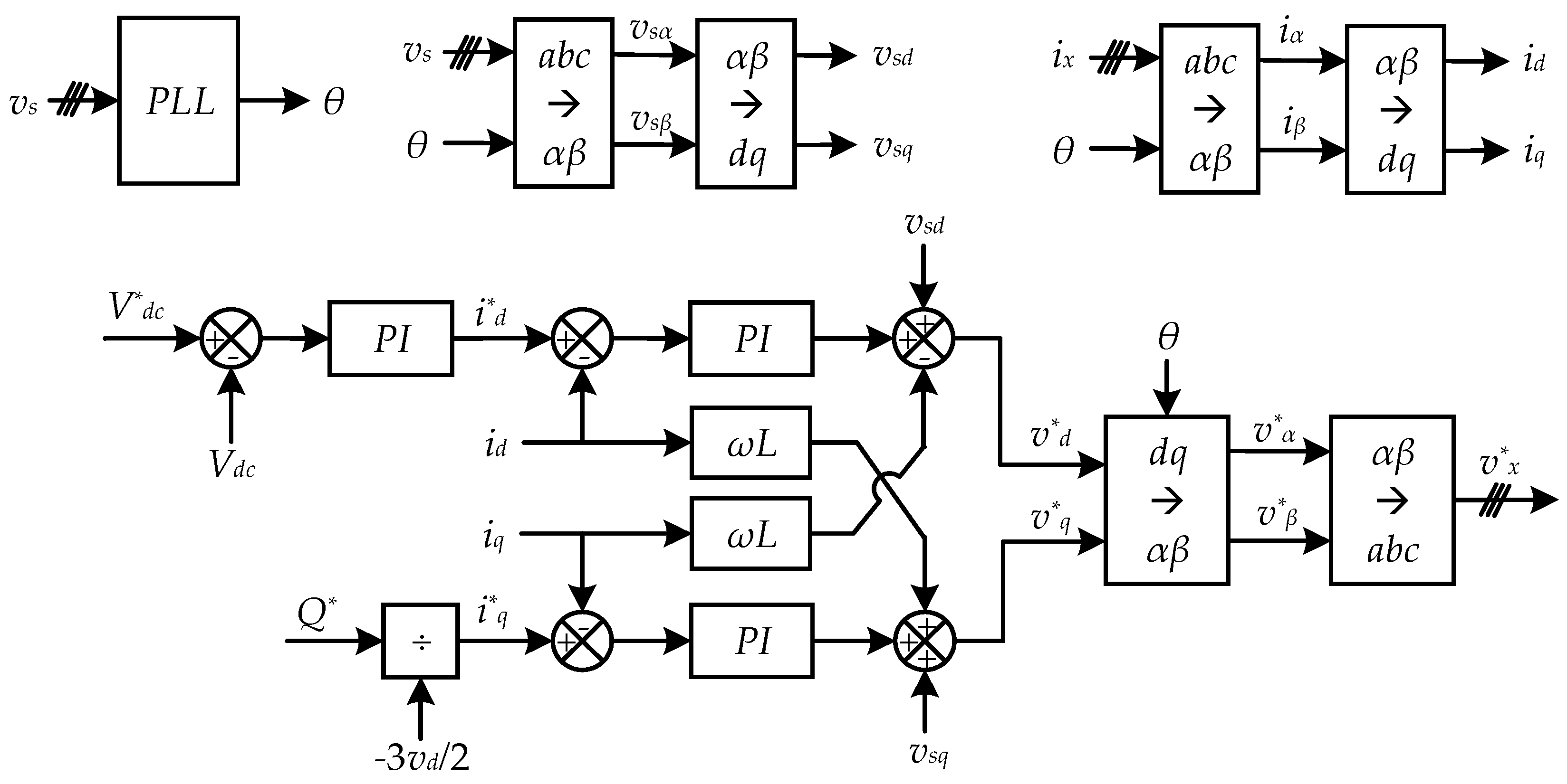
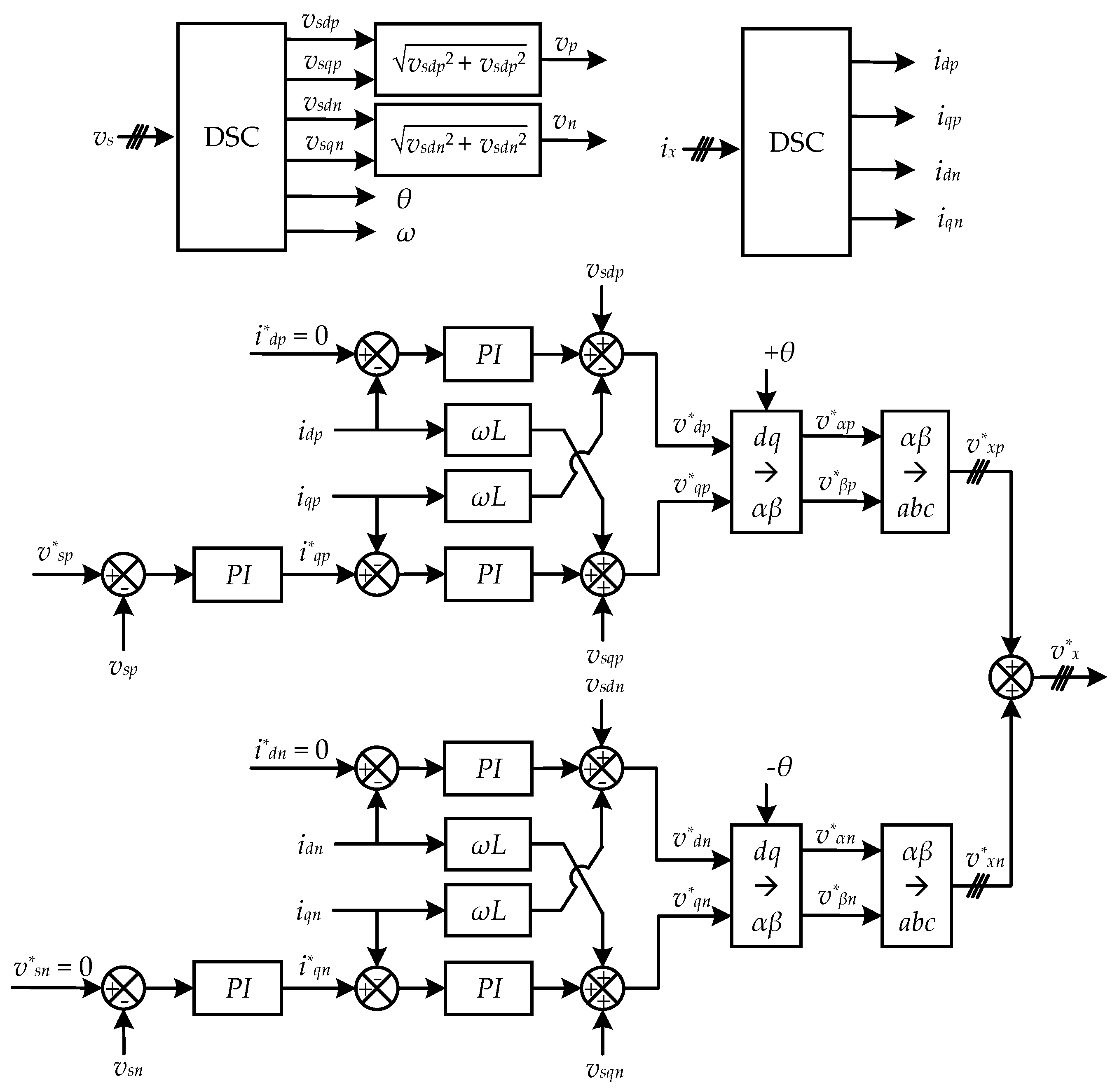
3.2. Output Voltage and Current Control

The MMC control strategies enable its high performance associated with superior safety, reliability, and efficiency. The control is challenging and sophisticated as involving substantial submodules and multiple control objectives related to the output voltage and current control, submodule voltage or SoC balancing control, and circulating current control. The MMC AC terminal can be connected to a renewable energy system, e.g., a wind turbine farm, or a high-voltage transport grid or medium-voltage distribution grid. Assuming the MMC is connected to the grid, as shown in Figure 7, the control of its output voltage and current vary under different grid conditions such as a balanced grid, unbalanced grid, and distorted grid [4].
In most cases, the AC side is assumed to interface a balanced utility only involving a fundamental component. The MMC output voltage and current control can be achieved by using the outer voltage control and inner current control. The inner current control is required to satisfy the command of active and reactive power based on the instantaneous power theory coordinated in a reference frame [84,85]. Generally, in the synchronous rotating dq-frame, assuming the d axis is completely aligned with the rotating vector of source voltage, the active power and reactive power can be expressed by
P = 3 2 v s d i d
Q = 3 2 v s q i q
where P and Q are the active and reactive power, respectively, v s d and v s q represent the d component and q component of the source voltage, and i d and i q give the reference currents i d * and i q * in dq axes. Using Equations (27) and (28), the active and reactive power can be managed by regulating i d and i q independently. The output voltage in dq-axes can be expressed as
v d = v s d + L s d i d d t + r s i d ω L s i q
v q = v s q + L s d i q d t + r s i q + ω L s i d
where v d and v q represent the d and q components of the MMC AC-side voltage,   L s and r s donate the inductance and resistance at the grid side, and ω is the fundamental angular frequency.
In addition, the DC-link voltage should maintain at the setpoint, which can be realized by the power balance between the AC terminal and DC terminal.
P = 3 2 v s d i d = V d c i d c
From Equation (31), the DC voltage can be used to produce the reference current in the d component. Therefore, the control block of the output voltage and current is demonstrated in Figure 8.
When unbalanced loads are connected or main failures occur in the grid, the grid voltage is unbalanced, resulting in an invalid injection of active power and limited restoration of reactive power. The output voltage and current must be controlled with independent control loops regarding positive and negative sequence grid components. A method is referred to as Delayed Signal Cancellation (DSC) [86]; it facilitates the calculation of the positive and negative sequence components. The control scheme of the output voltage and current control under unbalance grid conditions is depicted in Figure 9 [87]. The positive and negative sequence currents in d components are regulated with the effect of active power, and the command values are set to zero, as the active power ought to be zero. The positive and negative sequence voltages are controlled in the manner of reactive power by using PI controllers. The voltage references for positive and negative sequence are set to the grid voltage nominal value and zero, respectively.
Distorted grid is another abnormal condition of the grid system in which the grid voltage involves fundamental component and multiple harmonics. These harmonics cause voltage distortion, additional power losses in converters, and the malfunction of sensitive electronic devices. Therefore, it is necessary to apply a control method to eliminate multiple harmonics for the distorted grid. The harmonic components are normally at (6n ± 1)ω1, n = 1,2,3,..., in the three-phase system where the even-order and triple-order harmonics are naturally eliminated. The sequence of (6n - 1)ω1 harmonics are consistent with the sequence of a fundament component (positive/negative), whereas (6n + 1)ω1 harmonics are opposite to the fundamental sequence (negative/positive) [88].
It is argued that the PI controller is not suitable for harmonics elimination in the distorted grid due to its limited performance when dealing with sinusoidal reference signals and periodic disturbances [89]. The preferred control schemes [90] are based on selective harmonic compensation by using proportional resonant (PR) controllers or nonlinear and predictive approaches and repetitive control. Among them, the PR controller is widely used to eradicate the harmonics in the specific order. Figure 10 illustrates two control approaches based on PR controllers in the αβ and dq-frame [91] and αβ frame under distorted grid condition [92].

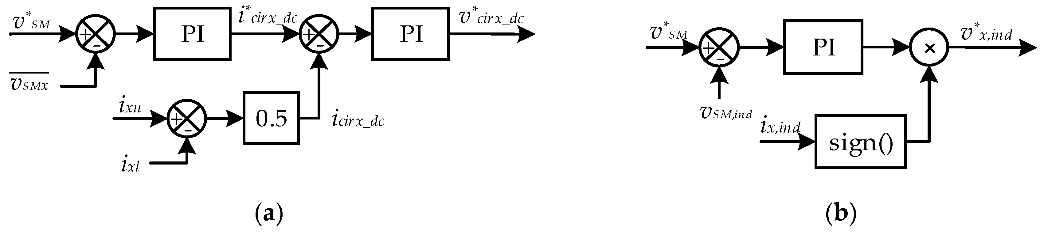
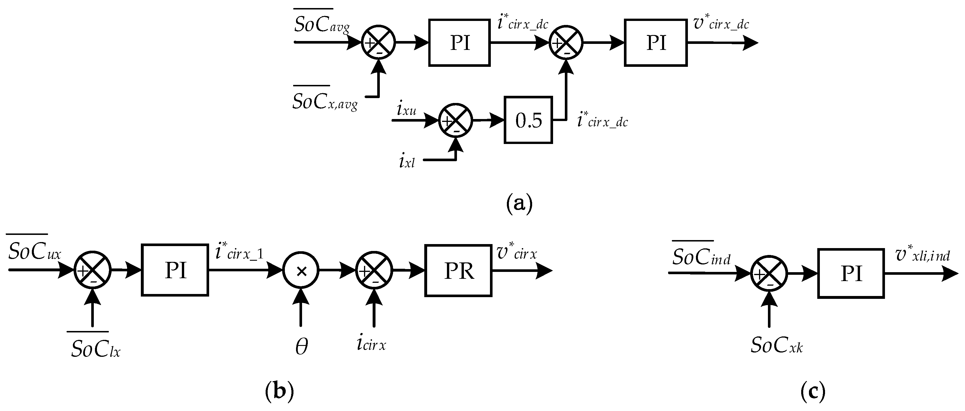
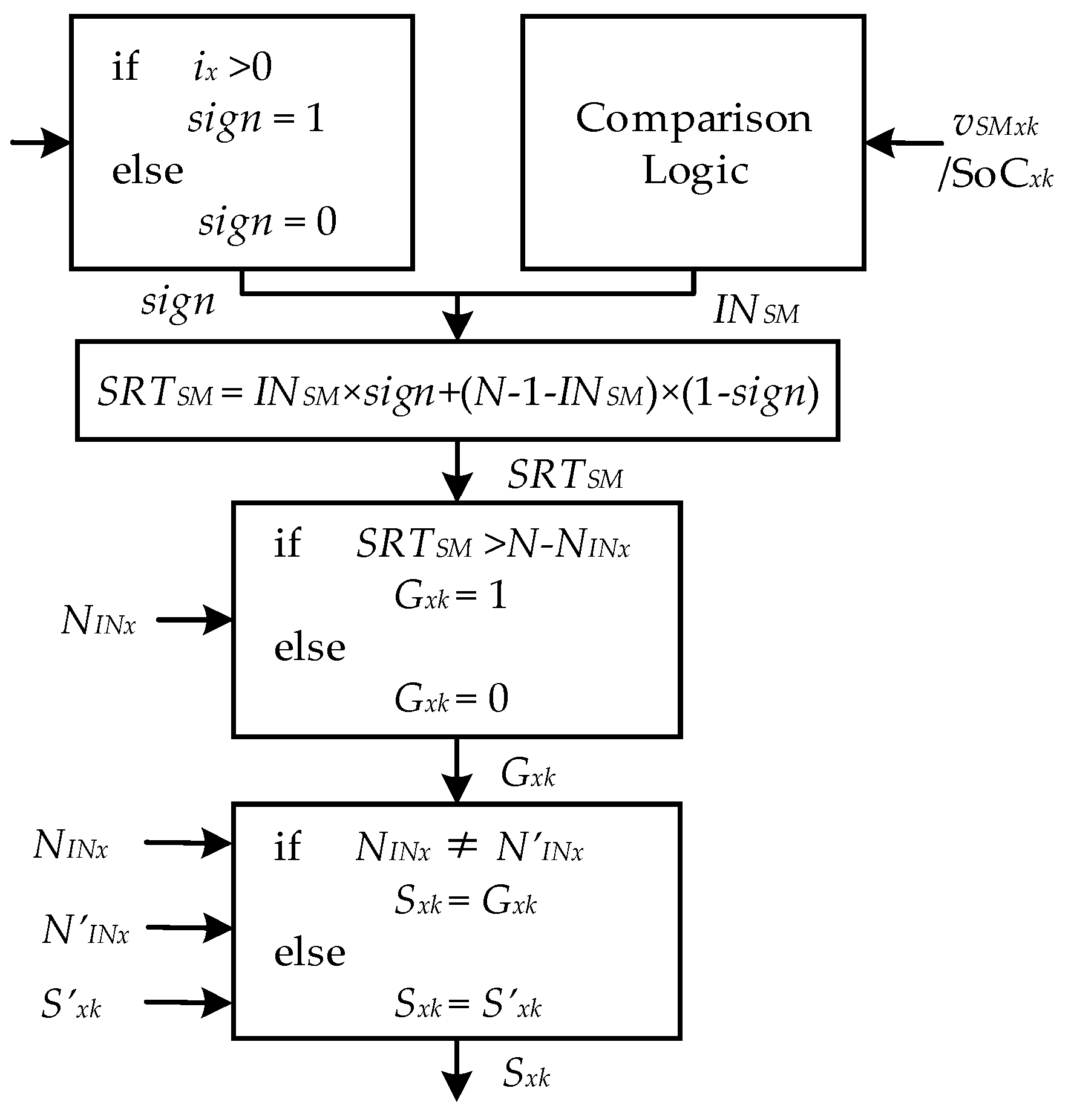
3.3. Submodule Balancing Control

The submodule balancing control in the MMC mainly involves leg/arm voltage balancing control, submodule capacitor voltage balancing control, or SoC balancing control if based on a battery submodule. Various submodule balancing schemes have been discussed and presented in the literature. These approaches are mainly based on individual voltage/SoC control or a sorting algorithm to equilibrate between submodules. Generally, when a small number of submodules are explored in the converter, the individual voltage/SoC control can be applied to realize the individual voltage/SoC regulation; otherwise, the sorting algorithm is preferred in the application with increased submodules by selecting the inserted/bypassed submodules in order of priority [4]. The individual balancing control and sorting control are also well-known as distributed balancing control and centralized balancing control [5,93].
Due to the inconsistency of actual submodule parameters and the charging and discharging influence, the submodule capacitor voltage is likely to deviate from the setpoint. In addition, the frequent switching states also contribute to the capacitor voltage ripple. The inconsistent submodule capacitor voltage results in unequal arm and leg voltage, which will further lead to a circulating current increasing the power losses and worsening the submodule voltage balancing [3,75]. The individual submodule balancing can be achieved by using a closed-loop controller for each cell [94,95]. The leg voltage balancing can be achieved by involving PI controllers as depicted in Figure 11a. The average submodule voltage is compared with the setpoint and manipulated by a PI controller outputting the DC component of circulating currents reference. The actual DC component of circulating currents can be obtained through a low-pass filter (LPF) or by averaging the upper arm and lower arm current. The individual voltage balancing algorithm regulates each submodule voltage with a PI controller separately (Figure 11b), and thus, the value of the individual control signal is relatively small. The signed block donates the direction of the current.
The submodule balancing control can be realized by using either the above-mentioned methods referred to as voltage-based control or the approaches involving energy-based control [79]. When the submodule capacitors are substituted by batteries as the energy source, the control objective changes to SoC balancing control, correspondingly. SoC balancing control involves SoC balancing between legs, arms, and individuals [80,81]. The control algorithm of SoC balancing resembles that of capacitor voltage control except for the SoC calculation. The arm SoC balancing control is realized by controlling the fundamental component of circulating currents shown in Figure 12b. The average SoCs of the upper and lower arms are compared and regulated by a PI controller yielding the amplitude of the fundamental component. The fundamental component is in-step phase with the reference and controlled by a proportional resonant (PR) controller to generate the arm SoC balancing control signal. On the basis of leg SoC and arm SoC balancing, a further individual SoC balancing control is conducted on each submodule battery, as demonstrated in Figure 12c.
Apart from employing PI controllers to realize the voltage balancing control or SoC balancing control, another widely used method refers to sorting balancing control [75,77], as illustrated in Figure 13. In the first step, the instantaneous value of the submodule capacitor voltage/battery SoC is measured, and the current direction is defined. According to the actual value, the submodule capacitor voltage/battery SoC is compared in a logic comparator to acquire an index number and further arranged in ascending or descending order depending on the current direction. Then, the final index number is compared with the reference index number, and submodules with the lowest voltages/SoC are selected and inserted if the current direction is positive and vice versa. The switching signal remains constant if it remains the same as in the previous cycle. Generally, the submodule balancing control using PI regulators produces a reference signal forming the modulation index and is arranged before PWM schemes, while the sorting balancing control is set after PWM methods to generate the final switching pulse.

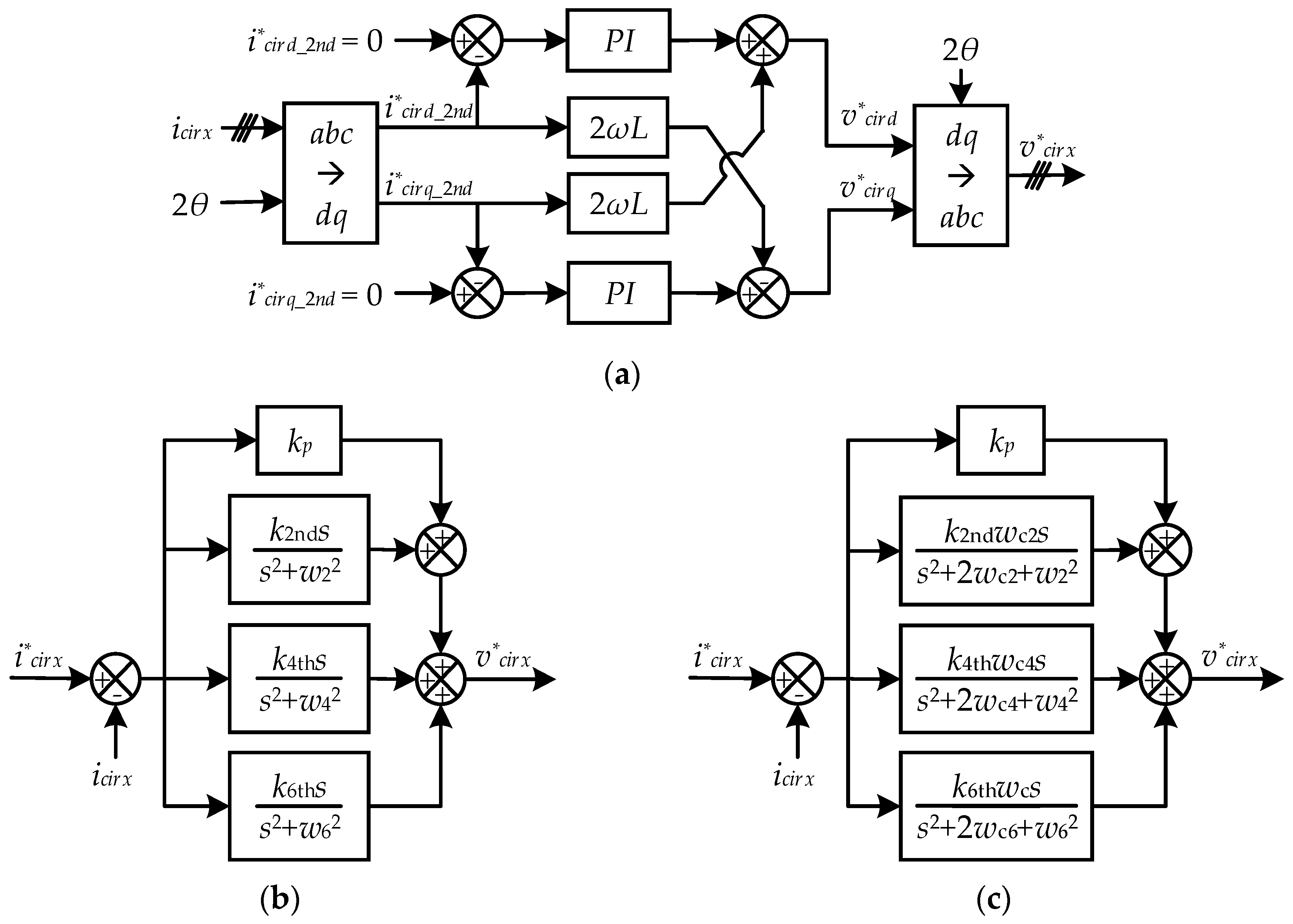
3.4. Circulating Current Control

The voltage difference between the upper and lower arms of the MMC legs results in the circulating current. The circulating current has little influence on the output voltages and currents at the AC side. However, it distorts the arm current, leading to extra power losses, a higher rating of devices, and submodule voltage ripples [96]. Therefore, the circulating current is expected to be eliminated. The arm inductors can suppress the circulating current to some extent [97]. Furthermore, the elimination controller is required to be employed. Since the circulating current is dominated by even-order harmonic components, especially second-order harmonics, the control objective of the elimination controller mainly focuses on the elimination of second-order harmonics [98]. The circulating current elimination approaches are based on decoupling control in the rotating dq-frame or resonant control in the stationary abc-frame. In terms of decoupling control, the second-order circulating current is converted into a d-axis and q-axis as DC components, which can be controlled easily and independently by PI regulators, as shown in Figure 14a [99,100]. In the case of unbalanced conditions where the circulating currents have positive, negative, and zero sequence components, the repetitive controller [101,102] can be applied to regulate multiple circulating current harmonics. Compared to decoupling methods, the proportional resonant controller has some advantages under unbalanced conditions with an easier implementation of multiple resonant controllers to eliminate a wider bandwidth of circulating current harmonics [103,104]. The resonant control structure to eliminate second-order, fourth-order, and sixth-order harmonics is described in Figure 14b [92,104]. In addition, for the sake of control robustness, the improved quasi proportional resonant controller is adopted to eliminate the circulating current, as shown in Figure 14c [105,106]. Except for eliminating the circulating current, the circulating current injection method is developed to reduce the submodule voltage ripple. Circulating current injection can be realized by the lookup table method [107] or the online calculation method based on instantaneous data [108].

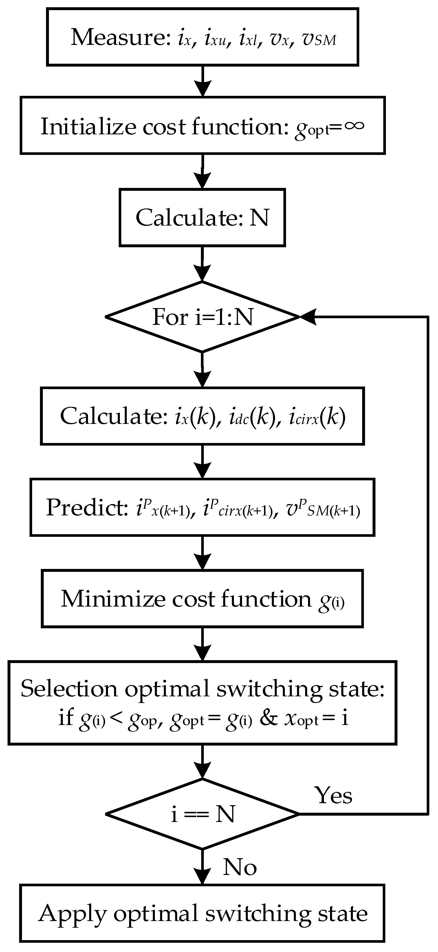
3.5. Nonlinear and Predictive Control

The MMC as a switching converter is a nonlinear system associated with multiple coupled variables. The conventional control methods are easy to implement in digital controllers by using linear techniques. However, these methods have a limitation on the dynamic response in terms of multiple control objectives such as AC current and voltage, leg/arm voltage, and circulating currents. To achieve simultaneous control and dynamic response, nonlinear and predictive control strategies are promising alternatives for MMC applications.
A nonlinear decoupling control based on feedback linearization [109] is proposed for MMC converters with the remaining linearized variables and linear controller to achieve desired transient responses and stability. Another nonlinear control method based on sliding mode control [110] is investigated with the faster dynamic response by splitting the state space into several subspaces, which are further controlled in an individual control structure. Passivity-based control [111,112], belonging to the nonlinear control strategies is applied to the MMC system based on an energy function to acquire a better dynamic and steady-state performance. The passivity-based control and sliding mode control are further combined in the MMC control system to improve the transient performance and robustness to system changes [113]. A nonlinear back-stepping control scheme [114], based on energy equations, is explored for single- and three-phase MMC by using Lyapunov theory with a simplified control structure in the abc frame. The back-stepping method is armed with the inherent feature of circulating current suppression and validated in simulation and experiments showing good dynamic response and robustness.
Predictive control, often referred to as model predictive control (MPC), is a preferable choice for power converters as it is a nonlinear control method. The MPC method can deal with multiple constraints in a single cost function and provide fast dynamic response and robustness against parameter variation and external disturbance. The finite control set MPC (FCS-MPC), also known as direct MPC, is a popular predictive approach used in MMC control. The implementation of FCS-MPC requires a discrete-time model of the MMC system which can be obtained from the discretization of the continuous-time model. The conversion from continuous-time to discrete-time can be achieved by using the forward Euler approximation or backward Euler approximation. A flow chart of the FCS-MPC [115] is depicted in Figure 15. One disadvantage of the FSC-MPC is the computational burden to obtain the optimal switching states, which worsens with increasing voltage levels. To deal with this issue, a fast FCS control scheme is investigated. Fast FCS-MPC [116], also known as indirect MPC, remains the submodule balancing strategy along with the predictive control. The predictive control is employed as the primary controller to control the output and circulating currents. Meanwhile, the submodule balancing strategy is applied as the secondary controller to equalize the submodule voltages or SoCs within the arm. The computational effort of the indirect FCS-MPC is minimized to a large extent, as only N+1 switching states are required to be evaluated for the optimal cost function.

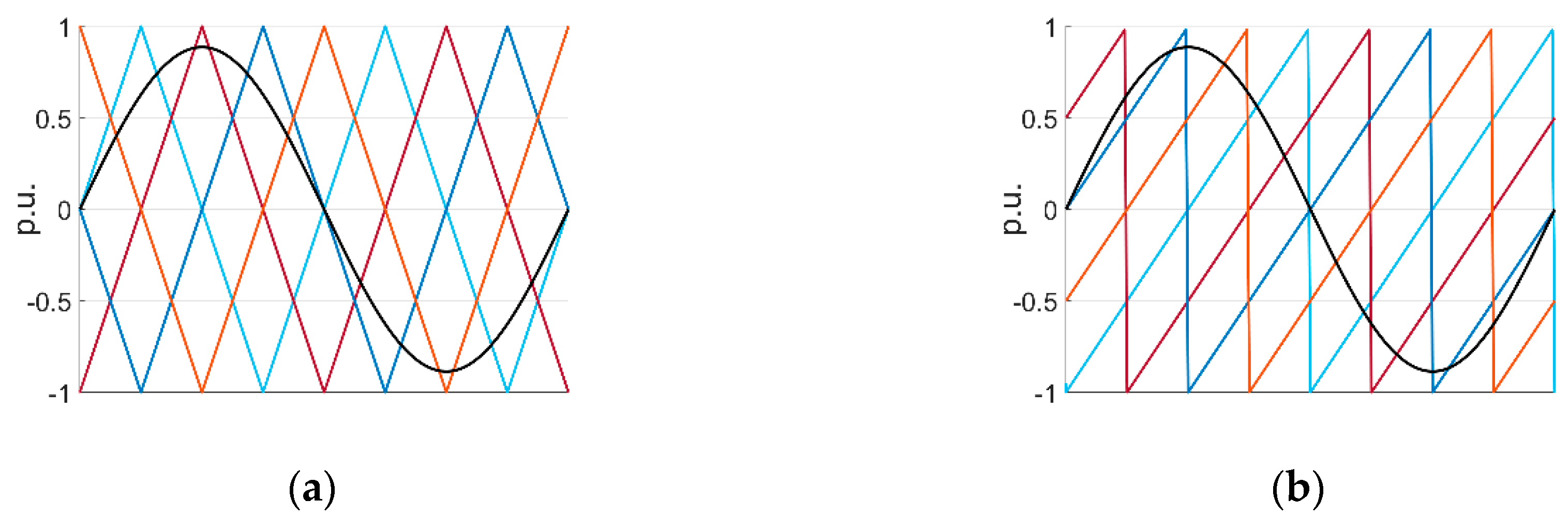
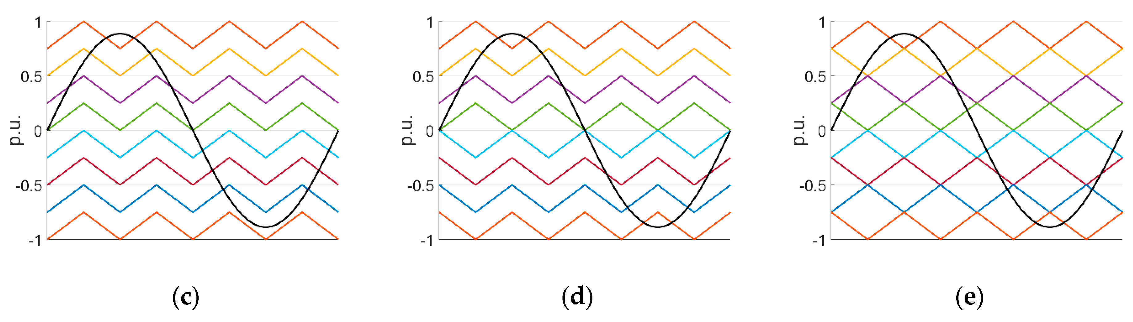
4. MMC Modulation Techniques

Various pulse width modulation (PWM) techniques have been developed to generate a desired output voltage for the MMC. These modulation techniques, depending on the switching frequency, can be classified as high switching frequency PWM (HSF-PWM), low switching frequency (LSF-PWM), and fundamental switching frequency (FSF-PWM) modulation scenarios [3,5]. The semiconductor switching losses increase with the switching frequency. As a result, the high switching frequency method is generally utilized when a small number of submodules are employed, whereas low switching frequency and fundamental switching frequency schemes are preferred when substantial submodules are involved [4].
Carrier-based PWM is a typical HSF-PWM method in which, for multilevel converters, the modulation reference of each phase is compared with multiple carrier waveforms to create the gating signals [34]. Triangular or sawtooth waveforms are prevalently applied as the compared carrier signals. The reference signals are produced by involving application-oriented control strategies, for example, voltage-oriented control (VOC) and field-oriented control (FOC), and they can be given as [77]
v x = m × V d c 2 sin ( ω t + φ x )
where v x is the phase modulation reference, m is the amplitude of modulation index in the range [0, 1], ω is the fundamental angular frequency, and φ x is the phase angle of {0, 2π/3, 4π/3}.
Carrier-based modulation schemes, based on the arrangement of multiple carriers, are categorically divided as phase-shifted carrier-based (PSC-PWM) and level-shifted carrier-based (LSC-PWM) techniques [117], as seen in Figure 15. In PSC-PWM, N identical triangular carrier waveforms are employed and displaced horizontally with a phase shift 2π/N. By comparing the modulation signals with the N carrier signals, the MMC can produce an output voltage with N+1 levels. The carrier waveforms in the upper and lower arm can be arranged with an interval angle π/N, with which the power converter can generate (2N + 1)-level output voltage [43,118]. The latter approach reduces the harmonic distortion of the output voltage with approximately double voltage levels at the cost of additional computation burden. Thanks to the independent modulation signal for each submodule, the PSC-PWM method imposes equal-distributed power stresses and switching losses on the semiconductors and contributes to the submodule capacitor voltage balancing [119]. The PSC-PWM approach is widely used in the multilevel power conversion system.
Using LSC-PWM, it produces (N+1)-level output voltage at the AC side involving N carrier signals with uniform magnitude and frequency disposed sequentially in line with zero axis [120,121]. The LSC-PWM strategy has three subfamily members including phase-disposition (PD-PWM), phase-opposition-disposition (POD-PWM), together with alternate phase-opposition-disposition (APOD-PWM). The different modulation techniques are illustrated in Figure 16. Although the LSC-PWM approach can be easily implemented to produce multilevel voltage, it is less preferred in the MMC application, since it causes uneven voltage distribution across the submodule capacitors, which results in a higher harmonic distortion of output voltage and leads to an increase of circulating currents. To overcome this situation, a series of rotation techniques regarding carrier or reference signals, e.g., a carrier rotation technique [122], a modified carrier rotation technique [123], or a signal rotation technique [120], are proposed to equally arrange submodule capacitor voltage. Furthermore, the optimized PD-PWM are developed with a selective loop bias mapping technique [124] or interleaving angle method [125] to reduce total harmonic distortion and balance submodule capacitor voltage naturally.
The switching frequency of space vector modulation (SVM) falls into the category of the LSF-PWM scheme. It is advantageous to select the switching vectors and arrange the switching sequences with more freedom in SVM-PWM. SVM-PWM has demonstrated good performance with superior harmonic features and DC-link utilization in the two-level converter [126]. However, when it comes to multilevel modulation, the SVM-PWM algorithm is challenging to implement with the significantly increased computational burden and complexity [1]. For the case of N levels, the figures of switching vectors and triangles soar to N 3 and 6 ( N 1 ) 2 , respectively [3]. To simplify multilevel SVM-PWM applied in the MMC, an improved scheme is proposed by decomposing the multilevel space vector into several two-level space vectors [127]. This method can easily be extended to multilevel converters with a reduced computational cost. Another low switching frequency modulation approach referred to sampled average modulation (SAM) has a similar process to SVM-PWM but with less computation complexity and simple implementation to multilevel converters with any number of submodules [128]. In SAM-PWM, the command voltage is produced by averaging the two nearest voltage levels and avoiding zero vectors in each sampling interval.
In terms of fundamental switching frequency modulation, a quite popular method is nearest level modulation (NLM) [129,130]. In this approach, the switching states and dwell time are directly derived from the command voltage eliminating the use of carrier signals. It is easy and practical to implement, especially in the case of MMC involving a large number of submodules. Selective harmonic elimination (SHE) also belongs to the category of FSF-PWM. SHE-PWM [131] can provide a high performance of output voltages. However, this method is difficult to implement due to the heavy calculation of substantial switching angles with multilevel voltages. An overview and comparison of different modulation techniques regarding modulation categories, switching frequency, application with the employed number of submodules, output harmonic performance, and implementation effort are presented in Table 2.

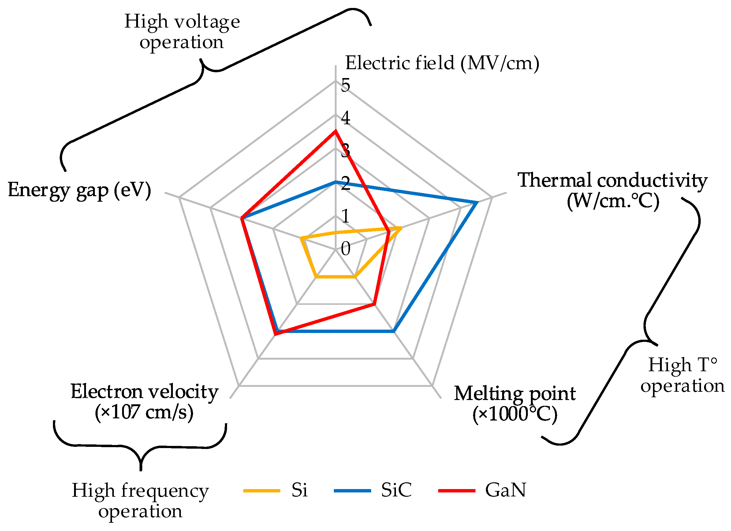
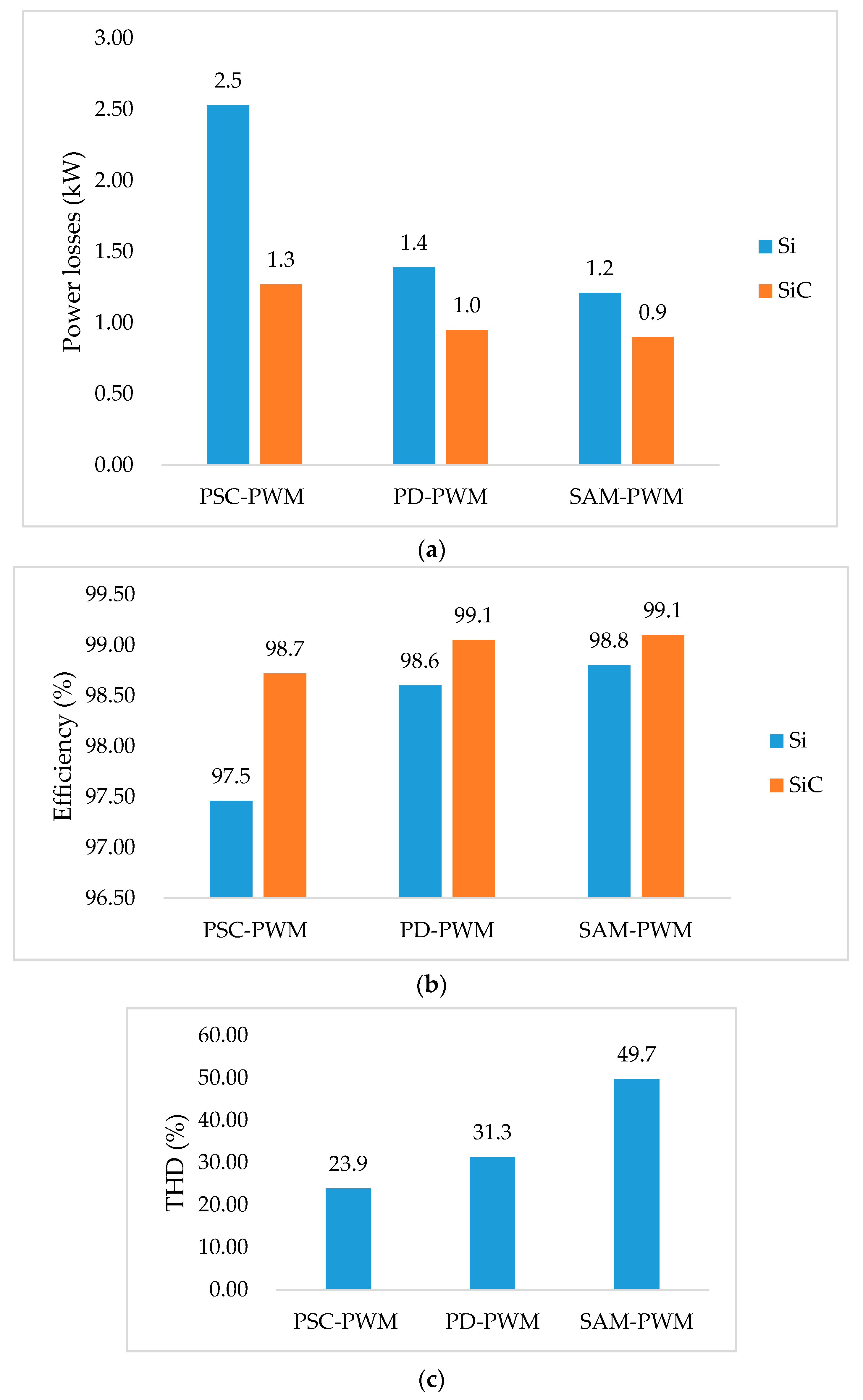
5. Power Losses and WBG Technology

Wideband gap (WBG) semiconductors, made on silicon carbide (SiC) and gallium nitride (GaN) provide advantages of increased energy efficiency, high power density, and cooling density thanks to improved electrical and thermal conductivities [132,133]. WBG transistors are expected to occupy a wide range of power conversion applications which are dominated by the traditional Si-based power devices over the past decades. Figure 17 [134,135] accounts for the competitive advantages for WBG power modules over classical Si-based switches in the condition of high voltage, high frequency, and high-temperature operation. For low-voltage applications, GaN power modules, where all the electrodes are arranged on the top layer due to the lateral structure, are preferred as a result of significantly reduced on-state resistance with high switching frequency. In contrast, SiC switches are much more competitive for higher voltage applications because of the easily scalable voltage and current with a vertical conduction path [136].
Power loss calculation is critical for thermal management and cooling in terms of applications with high power density. Power losses for WBG and Si-based semiconductors consist of conduction and switching losses. The low on-state resistance of WBG power devices contributes to a reduced conduction loss compared with Si-based modules. Generally, a freewheeling diode is connected to the semiconductor to ensure current continuity, which contributes additional power losses during reverse recovery behavior.
During the power losses calculation, the effect of temperature on the switching devices is neglected to simplify the loss model. The conduction loss for power switches is calculated within one fundamental period [137,138] which is obtained by
P c o n T = 1 T t 0 t 0 + T i T ( t ) v T ( t ) d t = 1 T t 0 t 0 + T i T ( t ) ( V T 0 + R T i T ( t ) ) d t
P c o n D = 1 T t 0 t 0 + T i F ( t ) v F ( t ) d t = 1 T t 0 t 0 + T i F ( t ) ( V D 0 + R D i F ( t ) ) d t
where P c o n T and P c o n D stand for the conduction loss of the transistors and diodes, i T and i F are the conduction current, V T 0 and V D 0 donate the saturation voltage, and R T and R D represent the slope resistance, respectively.
Switching loss is related to the count of all the switching actions during each fundamental period, since energy is charged and discharged by the inherent capacitor during each transition of turning on and turning off period. The switching loss is calculated by using a look-up table technique, and the calculation model is expressed by [137,138]
P o n T = 1 T i = 1 N i { v T ( t ) v T _ r e f E o n ( i T ( t ) ) } = 1 T i = 1 N i { v T ( t ) v T _ r e f i T ( t ) i T _ r e f E o n ( i T _ r e f ) }
P o f f T = 1 T i = 1 N i { v T ( t ) v T _ r e f E o f f ( i T ( t ) ) } = 1 T i = 1 N i { v T ( t ) v T _ r e f i T ( t ) i T _ r e f E o f f ( i T _ r e f ) }
P r e c D = 1 T i = 1 N i { v D ( t ) v D _ r e f E r e c ( i D ( t ) ) } = 1 T i = 1 N i { v D ( t ) v D _ r e f i F ( t ) i F _ r e f E r e c ( i F _ r e f ) }
where P o n T and P o f f T donate the turn-on and turn-off switching loss of the transistors and diodes,   P r e c D donates the diode reverse recovery loss, E o n and E o f f stand for the turn-on and turn-off energies of power switches, and E r e c is the diode reverse recovery energy. The switching energies are proportional to the ratios of the occurring blocking voltage ( v T and v D ) to the reference blocking voltage ( v T _ r e f and v D _ r e f ) and the switching current ( i T and i F ) to the reference current ( i T _ r e f and i F _ r e f ). Therefore, the total power losses P t o t can be calculated by the sum of the conduction and switching losses of transistors and diode, as
P t o t = P c o n + P s w = P c o n T + P c o n D + P o n T + P o f f T + P r e c D
The MMC efficiency is given by
η = ( 1 P t o t P M M C ) × 100 %
where η is the MMC efficiency and P M M C is the MMC power.
In order to assess the thermal performance of conventional Si-based semiconductors and WBG switching modules modulated by different modulation techniques for the MMC, the power losses calculation model is carried out with the simulation model in MATLAB by using the simulation parameters in Table 3. The comparative evaluation indexes include power losses and MMC efficiency. In addition, the total harmonic distortion (THD) of the output voltage is also investigated regarding different modulation methods. The modulation methods applied in the comparative study include PSC-PWM, PD-PWM, and SAM-PWM. PD-PWM is selected as a representative of LSC-PWM. SVM-PWM and SHE-PWM are excluded owing to their implementation complexity and calculation burden. In addition, the reason for not selecting NLM-PWM is that it is not suitable in application with a relatively small number of submodules, which leads to serious harmonic distortion. The switching frequency for both PSC-PWM and PD-PWM is set to 20 kHz, and the sampling rate for SAM-PWM is 2000 Hz. The semiconductor characteristics are extracted from the device datasheets CAS120M12BM2 and 2MBI150U2A-060.
The simulation results are demonstrated graphically as in Figure 18. Figure 18 illustrates the comparative performance based on semiconductor power losses, MMC efficiency, and output voltage THD by using different modulation methods. From Figure 18a,b, it is noticed that SiC modules, compared to Si devices, yield lower power losses and higher power efficiency for all the three modulation techniques. It is also indicated that the PSC-PWM has higher power losses following with the PD-PWM and SAM-PWM for both Si and SiC switches in Figure 18a, which leads to a reduced MMC efficiency, as shown in Figure 18b. In spite of lower performance in power losses and efficiency, Figure 18c manifests that PSC-PWM is prominent in providing good voltage quality with lower THD compared to the other two methods.
Furthermore, to investigate the influence of switching frequency on Si and SiC semiconductors concerning power losses and MMC efficiency, the switching frequency is set from 20 to 100 kHz. PSC-PWM is selected as the modulation scenario in this comparative study. The simulation results are given in Figure 19. It is observed that power losses are reduced considerably by employing SiC semiconductors compared to Si modules in Figure 19a. In particular, the power losses of Si power modules rise rapidly as the switching frequency increases, while those of the SiC devices increase much slower. This leads to a difference in terms of MMC efficiency, as shown in Figure 19b. It is noted that the MMC efficiency is capable of maintaining above 97% by using SiC switches at the switching frequency span of 20–100 kHz in this case, whereas the efficiency of Si-based MMC decreases to around 92% at the switching frequency of 100 kHz. The comparison of performance indicates that the differences in the material properties of switching devices lead to the fact that the WBG components have superior performance regarding reduced power losses and higher power efficiency, especially at the high switching frequency. The advantages of WBG power transistors can further substantially reduce the size of whole power conversion systems with strong robustness. It is expectable that WBG power switches will play a prominent role together with the MMC in the power conversion applications in the near future.

6. Conclusions

The MMC is expected to be a preferable choice in the medium and high-voltage power applications with intrinsic advantages such as scalable multilevel output voltage, low harmonic content of output voltage and output current, modular and flexible design, improved efficiency, and redundancy. As an application-oriented topology, it is predictable that the MMC will be guided to be more customized and well-adapted in the specific application area in terms of power transmission and quality improvement. This paper reviews the MMC with respect to the submodule and overall topologies, mathematical modeling and control methods, modulation techniques, and power losses with the incorporation of WBG technology. For submodule topology, the HBSM, owing to its simple architecture and low cost, maintains the domination in commercial utilization among a variety of submodule configurations. Newly developed submodule circuits could be investigated along with a comparative study to compete and balance between module size and cost as well as switching losses and fault tolerance. New advanced topologies could be explored to output better performance and meet different load requirements with the overall structure of the MMC, especially under fluctuating or unbalanced load. With respect to MMC control, the output voltage and current control under different grid conditions, submodule balancing control, and circulating current control are discussed. The challenging issues include the submodule balancing control, circulating current control, multiple variables’ simultaneous control, and the complexity of consequent control. Nonlinear and predictive control strategies could be promising alternatives compared to conventional control methods. Modulation techniques are reviewed and classified according to switching frequency with decent application area and implementation effort. Power losses are investigated with the incorporation of WBG technology by using different modulation methods and with different switching frequencies. The comparison of performance indicates that PSC-PWM has better output performance while generating higher power losses compared to PD-PWM and SAM-PWM, and the WBG semiconductors have superior performance regarding reduced power losses and higher power efficiency, especially at the high switching frequency. The incorporation of WBG technology will facilitate the MMC application with further advantages of high-voltage and high-power operations, low power losses, high efficiency, improved reliability, and reduced module size and cooling system. Finally, this review research focuses on the topology, modeling, control, and modulation techniques of the MMC for stationary applications, and future work will survey the MMC for vehicular applications.

Author Contributions

Y.W. reviewed and wrote the first version of the paper; A.A. contributed to modeling the simulation and editing the paper; T.G. reviewed the MMC control and improved the structure of the paper; S.B.O. and O.C.K. contributed by analyzing the results and editing the paper; O.H. reviewed and edited the manuscript and also supervised this research study. All authors have read and agreed to the published version of the manuscript.

Funding

This study was funded by China Scholarship Council (CSC).

Acknowledgments

Yang Wang was sponsored by China Scholarship Council. The authors also acknowledge Flanders Make for the support of this research study.

Conflicts of Interest

The authors declare no conflict of interest.

References

  1. Lesnicar, A.; Marquardt, R. An innovative modular multilevel converter topology suitable for a wide power range. In Proceedings of the 2003 IEEE Bologna Power Tech Conference, Bologna, Italy, 23–26 June 2003; Volume 3, pp. 272–277. [Google Scholar]
  2. Friedrich, K. Modern HVDC PLUS application of VSC in Modular Multilevel Converter topology. In Proceedings of the 2010 IEEE International Symposium on Industrial Electronics, Bari, Italy, 4–7 July 2010; pp. 3807–3810. [Google Scholar]
  3. Du, S.; Dekka, A.; Wu, B.; Zargari, N. Modular Multilevel Converters: Analysis, Control, and Applications; John Wiley & Sons, Inc.: Hoboken, NJ, USA, 2017; ISBN 9781119367291. [Google Scholar]
  4. Martinez-Rodrigo, F.; Ramirez, D.; Rey-Boue, A.B.; De Pablo, S.; Herrero-De Lucas, L.C. Modular multilevel converters: Control and applications. Energies 2017, 10, 1709. [Google Scholar] [CrossRef] [Green Version]
  5. Raju, M.N.; Sreedevi, J.; Mandi, R.P.; Meera, K.S. Modular multilevel converters technology: A comprehensive study on its topologies, modelling, control and applications. IET Power Electron. 2019, 12, 149–169. [Google Scholar] [CrossRef]
  6. Lyu, D.; Sun, Y.; Teixeira, C.A.; Holmes, D.G.; McGrath, B.P.; Wang, Q. A Novel Modular Multilevel Converter with Coupled-inductor Semi-bridge Submodules. In Proceedings of the 2019 IEEE Energy Conversion Congress and Exposition (ECCE), Baltimore, MD, USA, 29 September–3 October 2019; Volume 40, pp. 6860–6867. [Google Scholar]
  7. Alyami, H.; Mohamed, Y. Review and development of MMC employed in VSC-HVDC systems. In Proceedings of the 2017 IEEE 30th Canadian Conference on Electrical and Computer Engineering (CCECE), Windsor, ON, Canada, 30 April–3 May 2017; pp. 1–6. [Google Scholar]
  8. Li, Y.; Guo, J.; Zhang, X.; Wang, S.; Ma, S.; Zhao, B.; Wu, G.; Wang, T. Over-Voltage Suppression Methods for the MMC-VSC-HVDC Wind Farm Integration System. IEEE Trans. Circuits Syst. II Express Briefs 2020, 67, 355–359. [Google Scholar] [CrossRef]
  9. Chakraborty, S.; Vu, H.-N.; Hasan, M.M.; Tran, D.-D.; El Baghdadi, M.; Hegazy, O. DC-DC Converter Topologies for Electric Vehicles, Plug-in Hybrid Electric Vehicles and Fast Charging Stations: State of the Art and Future Trends. Energies 2019, 12, 1569. [Google Scholar] [CrossRef] [Green Version]
  10. Du, S.; Wu, B.; Zargari, N.R.; Cheng, Z. A Flying-Capacitor Modular Multilevel Converter for Medium-Voltage Motor Drive. IEEE Trans. Power Electron. 2017, 32, 2081–2089. [Google Scholar] [CrossRef]
  11. Du, S.; Wu, B.; Tian, K.; Zargari, N.; Cheng, Z. An Active Cross-Connected Modular Multilevel Converter (AC-MMC) for Medium-voltage Motor Drive. IEEE Trans. Ind. Electron. 2016, 63, 1. [Google Scholar] [CrossRef]
  12. Chakraborty, S.; Maiti, S. A Novel Modular Multilevel Converter for Medium Voltage Variable Speed Induction Motor Drives. In Proceedings of the 45th Annual Conference of the IEEE Industrial Electronics Society (IECON 2019), Lisbon, Portugal, 14–17 October 2019; pp. 6049–6054. [Google Scholar]
  13. Verdugo, C.; Candela, J.I.; Blaabjerg, F.; Rodriguez, P. Three-Phase Isolated Multimodular Converter in Renewable Energy Distribution Systems. IEEE J. Emerg. Sel. Top. Power Electron. 2020, 8, 854–865. [Google Scholar] [CrossRef]
  14. Bayat, H.; Yazdani, A. A Hybrid MMC-Based Photovoltaic and Battery Energy Storage System. IEEE Power Energy Technol. Syst. J. 2019, 6, 32–40. [Google Scholar] [CrossRef]
  15. Cao, S.; Lin, N.; Dinavahi, V. Faster-Than-Real-Time Dynamic Simulation of AC/DC Grids on Reconfigurable Hardware. IEEE Trans. Power Syst. 2020, 35, 1539–1548. [Google Scholar] [CrossRef]
  16. Hillers, A.; Biela, J. Fault-tolerant operation of the modular multilevel converter in an energy storage system based on split batteries. In Proceedings of the 2014 16th European Conference on Power Electronics and Applications, Lappeenranta, Finland, 26–28 August 2014; pp. 1–8. [Google Scholar]
  17. Sangiri, J.B.; Raiesh, V.; Chattopadhyay, S.K.; Chakraborty, C. Modular Multilevel Converter for Multifunctional Battery Management System of Electric Vehicle. In Proceedings of the 44th Annual Conference of the IEEE Industrial Electronics Society (IECON 2018), Washington, DC, USA, 21–23 October 2018; pp. 1333–1338. [Google Scholar]
  18. Li, N.; Gao, F. Linearized operation of MMC battery energy storage system. In Proceedings of the 2016 IEEE 2nd Annual Southern Power Electronics Conference (SPEC), Auckland, New Zealand, 5–8 December 2016; pp. 1–5. [Google Scholar]
  19. Tianqi, L.; Youyin, W.; Zhanjun, L.; Meijun, L.; Weimao, X.; Yunche, S.; Zhijian, C.; Na, Z. Reactive Power Compensation and Control Strategy for MMC-STATCOM Doubly-Fed Wind Farm. In Proceedings of the 2019 IEEE Innovative Smart Grid Technologies—Asia (ISGT Asia), Chengdu, China, 21–24 May 2019; pp. 3537–3542. [Google Scholar]
  20. Zhang, Y.; Chen, X.; Sun, J. Sequence Impedance Modeling and Analysis of MMC in Single-Star Configuration. IEEE Trans. Power Electron. 2020, 35, 334–346. [Google Scholar] [CrossRef]
  21. Mao, M.; Ding, Y.; Chang, L.; Hatziargyriou, N.D.; Chen, Q.; Tao, T.; Li, Y. Multi-Objective Power Management for EV Fleet With MMC-Based Integration Into Smart Grid. IEEE Trans. Smart Grid 2019, 10, 1428–1439. [Google Scholar] [CrossRef]
  22. Del Pizzo, A.; Coppola, M.; Spina, I. Current waveforms distribution among electrochemical cells of Modular Multilevel Converters in Battery Electric Vehicles. In Proceedings of the 2018 IEEE International Conference on Electrical Systems for Aircraft, Railway, Ship Propulsion and Road Vehicles & International Transportation Electrification Conference (ESARS-ITEC), Nottingham, UK, 7–9 November 2018; pp. 1–4. [Google Scholar]
  23. Ashourloo, M.; Zaman, M.S.; Nasr, M.; Trescases, O. Opportunities for Leveraging Low-Voltage GaN Devices in Modular Multi-level Converters for Electric-Vehicle Charging Applications. In Proceedings of the 2018 International Power Electronics Conference (IPEC-Niigata 2018—ECCE Asia), Niigata, Japan, 20–24 May 2018; pp. 2380–2385. [Google Scholar]
  24. Nademi, H.; Zadeh, M.; Undeland, T. Interfacing an Electric Vehicle to the Grid with Modular Conversion Unit: A Case Study of a Charging Station and its Control Framework. In Proceedings of the 44th Annual Conference of the IEEE Industrial Electronics Society (IECON 2018), Washington, DC, USA, 21–23 October 2018; pp. 5171–5176. [Google Scholar]
  25. Mahmoud, A.A.; Hafez, A.A.; Yousef, A.M. Modular Multilevel Converters for Renewable Energies Interfacing: Comparative review. In Proceedings of the 2019 IEEE Conference on Power Electronics and Renewable Energy (CPERE), Aswan, Egypt, 23–25 October 2019; pp. 397–406. [Google Scholar]
  26. Wang, S.; Ahmed, K.H.; Adam, G.P.; Massoud, A.M.; Williams, B.W. A Novel Converter Station Structure for Improving Multiterminal HVDC System Resiliency Against AC and DC Faults. IEEE Trans. Ind. Electron. 2020, 67, 4270–4280. [Google Scholar] [CrossRef]
  27. Li, X.; Song, Q.; Liu, W.; Rao, H.; Xu, S.; Li, L. Protection of Nonpermanent Faults on DC Overhead Lines in MMC-Based HVDC Systems. IEEE Trans. Power Deliv. 2013, 28, 483–490. [Google Scholar] [CrossRef]
  28. Xu, J.; Zhao, P.; Zhao, C. Reliability Analysis and Redundancy Configuration of MMC With Hybrid Submodule Topologies. IEEE Trans. Power Electron. 2016, 31, 2720–2729. [Google Scholar] [CrossRef]
  29. Wei, J. Review of Current Control Strategies in Modular Multilevel Converter. Master’s Thesis, Norwegian University of Science and Technology, Trondheim, Norway, 2016. [Google Scholar]
  30. Kumar, Y.S.; Poddar, G. Balanced Submodule Operation of Modular Multilevel Converter-Based Induction Motor Drive for Wide-Speed Range. IEEE Trans. Power Electron. 2020, 35, 3918–3927. [Google Scholar] [CrossRef]
  31. Xu, Y.; Xu, Z.; Zhang, Z.; Xiao, H. A Novel Circulating Current Controller for MMC Capacitor Voltage Fluctuation Suppression. IEEE Access 2019, 7, 120141–120151. [Google Scholar] [CrossRef]
  32. Li, B.; Xu, Z.; Shi, S.; Xu, D.; Wang, W. Comparative Study of the Active and Passive Circulating Current Suppression Methods for Modular Multilevel Converters. IEEE Trans. Power Electron. 2018, 33, 1878–1883. [Google Scholar] [CrossRef]
  33. Perez, M.A.; Rodriguez, J.; Fuentes, E.J.; Kammerer, F. Predictive Control of AC–AC Modular Multilevel Converters. IEEE Trans. Ind. Electron. 2012, 59, 2832–2839. [Google Scholar] [CrossRef]
  34. Marquez, A.; Leon, J.I.; Vazquez, S.; Franquelo, L.G.; Perez, M. A comprehensive comparison of modulation methods for MMC converters. In Proceedings of the 43rd Annual Conference of the IEEE Industrial Electronics Society (IECON 2017), Beijing, China, 29 October–1 November 2017; pp. 4459–4464. [Google Scholar]
  35. Shenai, K. Future Prospects of Widebandgap (WBG) Semiconductor Power Switching Devices. IEEE Trans. Electron Devices 2015, 62, 248–257. [Google Scholar] [CrossRef]
  36. Bhesaniya, M.M.; Shukla, A. Norton Equivalent Modeling of Current Source MMC and Its Use for Dynamic Studies of Back-to-Back Converter System. IEEE Trans. Power Deliv. 2017, 32, 1935–1945. [Google Scholar] [CrossRef]
  37. Adam, G.P.; Davidson, I.E. Robust and Generic Control of Full-Bridge Modular Multilevel Converter High-Voltage DC Transmission Systems. IEEE Trans. Power Deliv. 2015, 30, 2468–2476. [Google Scholar] [CrossRef] [Green Version]
  38. Yang, W.; Song, Q.; Xu, S.; Rao, H.; Liu, W. An MMC Topology Based on Unidirectional Current H-Bridge Submodule With Active Circulating Current Injection. IEEE Trans. Power Electron. 2018, 33, 3870–3883. [Google Scholar] [CrossRef]
  39. Yang, W.; Song, Q.; Zhao, B. Energy Storage Requirement and Low Capacitance Operation of Unidirectional Current H-Bridge Modular Multilevel Converters. IEEE Trans. Power Electron. 2019, 34, 11748–11759. [Google Scholar] [CrossRef]
  40. Gao, C.; Lv, J. A New Parallel-Connected Diode-Clamped Modular Multilevel Converter With Voltage Self-Balancing. IEEE Trans. Power Deliv. 2017, 32, 1616–1625. [Google Scholar] [CrossRef]
  41. Shu, H.; Lei, S.; Tian, X. A New Topology of Modular Multilevel Converter With Voltage Self-Balancing Ability. IEEE Access 2019, 7, 184786–184796. [Google Scholar] [CrossRef]
  42. Xiang, W.; Lin, W.; An, T.; Wen, J.; Wu, Y. Equivalent Electromagnetic Transient Simulation Model and Fast Recovery Control of Overhead VSC-HVDC Based on SB-MMC. IEEE Trans. Power Deliv. 2017, 32, 778–788. [Google Scholar] [CrossRef]
  43. Solas, E.; Abad, G.; Barrena, J.A.; Aurtenetxea, S.; Carcar, A.; Zajac, L. Modular Multilevel Converter With Different Submodule Concepts—Part I: Capacitor Voltage Balancing Method. IEEE Trans. Ind. Electron. 2013, 60, 4525–4535. [Google Scholar] [CrossRef]
  44. Solas, E.; Abad, G.; Barrena, J.A.; Aurtenetxea, S.; Carcar, A.; Zajac, L. Modular Multilevel Converter With Different Submodule Concepts—Part II: Experimental Validation and Comparison for HVDC Application. IEEE Trans. Ind. Electron. 2013, 60, 4536–4545. [Google Scholar] [CrossRef]
  45. Adam, G.P.; Abdelsalam, I.; Fletcher, J.E.; Burt, G.M.; Holliday, D.; Finney, S.J. New Efficient Submodule for a Modular Multilevel Converter in Multiterminal HVDC Networks. IEEE Trans. Power Electron. 2017, 32, 4258–4278. [Google Scholar] [CrossRef] [Green Version]
  46. Tang, Y.; Chen, M.; Ran, L. A compact MMC submodule structure with reduced capacitor size using the stacked switched capacitor architecture. IEEE Trans. Power Electron. 2015, 31, 1. [Google Scholar] [CrossRef]
  47. Marquardt, R. Modular Multilevel Converter Topologies with DC-Short Circuit Current Limitation. In Proceedings of the 8th International Conference on Power Electronics—ECCE Asia, Jeju, Korea, 29 May–2 June 2011; pp. 1425–1431. [Google Scholar]
  48. Zhang, Y.; Ravishankar, J.; Fletcher, J.; Li, R.; Han, M. Review of Modular Multilevel Converter Based Multi-terminal HVDC Systems for Offshore Wind Power Transmission. Renew. Sustain. Energy Rev. 2016, 61, 572–586. [Google Scholar] [CrossRef]
  49. Meng, X.; Han, J.; Bieber, L.M.; Wang, L.; Li, W.; Belanger, J. A Universal Blocking-Module-Based Average Value Model of Modular Multilevel Converters With Different Types of Submodules. IEEE Trans. Energy Convers. 2020, 35, 53–66. [Google Scholar] [CrossRef]
  50. Adam, G.P.; Ahmed, K.H.; Williams, B.W. Mixed Cells Modular Multilevel Converter. In Proceedings of the 2014 IEEE 23rd International Symposium on Industrial Electronics (ISIE), Istanbul, Turkey, 1–4 June 2014; pp. 1390–1395. [Google Scholar]
  51. Ji, M.; Wang, Y.; Tan, K.; Wang, C. A Voltage-balanced Hybrid MMC Topology for DC Fault Ride-through. In Proceedings of the 2019 IEEE Innovative Smart Grid Technologies—Asia (ISGT Asia), Chengdu, China, 21–24 May 2019; pp. 2282–2286. [Google Scholar]
  52. Nami, A.; Wang, L.; Dijkhuizen, F.; Shukla, A. Five Level Cross Connected Cell for Cascaded Converters. In Proceedings of the 2013 15th European Conference on Power Electronics and Applications (EPE), Lille, France, 3–5 September 2013; pp. 1–9. [Google Scholar]
  53. Elserougi, A.A.; Massoud, A.M.; Ahmed, S. A Switched-Capacitor Submodule for Modular Multilevel HVDC Converters With DC-Fault Blocking Capability and a Reduced Number of Sensors. IEEE Trans. Power Deliv. 2016, 31, 313–322. [Google Scholar] [CrossRef]
  54. Zhang, J.; Jiang, C.; Han, Y. Modular Multilevel Converter Composite Submodule Topology and Control. J. Eng. 2019, 2019, 2643–2648. [Google Scholar] [CrossRef]
  55. Debnath, S.; Qin, J.; Bahrani, B.; Saeedifard, M.; Barbosa, P. Operation, Control, and Applications of the Modular Multilevel Converter: A Review. IEEE Trans. Power Electron. 2015, 30, 37–53. [Google Scholar] [CrossRef]
  56. Nami, A.; Liang, J.; Dijkhuizen, F.; Demetriades, G.D. Modular Multilevel Converters for HVDC Applications: Review on Converter Cells and Functionalities. IEEE Trans. Power Electron. 2015, 30, 18–36. [Google Scholar] [CrossRef]
  57. Cai, Y.; Wen, M.; Chen, Y.; Shi, Y.; Qin, Y. Low DC Voltage Control Strategy of Bipolar LCC-MMC Hybrid HVDC Transmission System. In Proceedings of the 2017 2nd International Conference on Power and Renewable Energy (ICPRE), Chengdu, China, 20–23 September 2017; pp. 166–171. [Google Scholar]
  58. Jung, J.-J.; Cui, S.; Sul, S.-K. A New Topology of Multilevel VSC Converter for Hybrid HVDC Transmission System. In Proceedings of the 2016 IEEE Applied Power Electronics Conference and Exposition (APEC), Long Beach, CA, USA, 20–24 March 2016; pp. 2620–2628. [Google Scholar]
  59. Xia, X.; Zhou, Y.; Fu, C.; Zhou, Z.; He, Y. Research on High Voltage DC Transmission System Optimal Control Based on MMC. Int. J. Electr. Power Energy Syst. 2016, 82, 207–212. [Google Scholar] [CrossRef]
  60. Shi, G.; Chang, Y.; Cai, X.; Zhang, J. Bifurcate Modular Multilevel Converter for Low-modulation-ratio Applications. IET Power Electron. 2016, 9, 145–154. [Google Scholar] [CrossRef]
  61. Chang, Y.; Cai, X. A New Family of Modular Multilevel Converters. In Proceedings of the 2016 IEEE 8th International Power Electronics and Motion Control Conference (IPEMC-ECCE Asia), Hefei, China, 22–25 May 2016; Volume 1, pp. 3483–3488. [Google Scholar]
  62. Jin, L.; Dong, Z.; Deng, Y.; Zhou, L.; Lu, Y.; Yang, Y. Operation Range Analysis and Capacitor Voltage Regulation of A Dual-AC-Terminal MMC based on Bifurcated-Arm Topology. In Proceedings of the 2019 IEEE Energy Conversion Congress and Exposition (ECCE), Baltimore, MD, USA, 29 September–3 October 2019; pp. 6868–6874. [Google Scholar]
  63. Du, S.; Wu, B.; Zargari, N.R. A Star-Channel Modular Multilevel Converter for Zero/Low-Fundamental-Frequency Operation Without Injecting Common-Mode Voltage. IEEE Trans. Power Electron. 2018, 33, 2857–2865. [Google Scholar] [CrossRef]
  64. Du, S.; Wu, B.; Zargari, N. Delta-Channel Modular Multilevel Converter for a Variable-Speed Motor Drive Application. IEEE Trans. Ind. Electron. 2018, 65, 6131–6139. [Google Scholar] [CrossRef]
  65. Priya, M.; Ponnambalam, P.; Muralikumar, K. Modular-multilevel Converter Topologies and Applications—A Review. IET Power Electron. 2019, 12, 170–183. [Google Scholar] [CrossRef]
  66. Madichetty, S.; Abhijit, D.; Jinka, S. A Survey and Experimental Verification of Modular Multilevel Converters. Int. J. Power Electron. Drive Syst. 2014, 4, 363–375. [Google Scholar] [CrossRef]
  67. Kawamura, W.; Hagiwara, M.; Akagi, H. Control and Experiment of a Modular Multilevel Cascade Converter Based on Triple-Star Bridge Cells. IEEE Trans. Ind. Appl. 2014, 50, 3536–3548. [Google Scholar] [CrossRef]
  68. Karwatzki, D.; Mertens, A. Control Approach for a Class of Modular Multilevel Converter Topologies. In Proceedings of the 2016 IEEE Energy Conversion Congress and Exposition (ECCE), Milwaukee, WI, USA, 18–22 September 2016; pp. 1–9. [Google Scholar]
  69. Kammerer, F.; Kolb, J.; Braun, M. Fully Decoupled Current Control and Energy Balancing of The Modular Multilevel Matrix Converter. In Proceedings of the 2012 15th International Power Electronics and Motion Control Conference (EPE/PEMC), Novi Sad, Serbia, 4–6 September 2012; pp. LS2a.3-1–LS2a.3-8. [Google Scholar]
  70. Angkititrakul, S.; Erickson, R.W. Control and Implementation of a New Modular Matrix Converter. In Proceedings of the Nineteenth Annual IEEE Applied Power Electronics Conference and Exposition (APEC ’04), Anaheim, CA, USA, 22–26 February 2004; Volume 2, pp. 813–819. [Google Scholar]
  71. Liu, S.; Wang, X.; Wang, B.; Sun, P.; Zhou, Q.; Cui, Y. Comparison between Back-to-back MMC and M3C as High Power AC/AC Converters. In Proceedings of the 2016 IEEE PES Asia-Pacific Power and Energy Engineering Conference (APPEEC), Xi’an, China, 25–28 October 2016; pp. 671–676. [Google Scholar]
  72. Baruschka, L.; Mertens, A. A New 3-phase AC/AC Modular Multilevel Converter with Six Branches in Hexagonal Configuration. In Proceedings of the 2011 IEEE Energy Conversion Congress and Exposition, Phoenix, Arizona, 16–21 September 2011; pp. 4005–4012. [Google Scholar]
  73. Blaszczyk, P. Hex-Y—A New Modular Multilevel Converter Topology for a Direct AC-AC Power Conversion. In Proceedings of the 2018 20th European Conference on Power Electronics and Applications (EPE ’18 ECCE Europe), Riga, Latvia, 17–21 September 2018; pp. P.1–P.10. [Google Scholar]
  74. Blaszczyk, P. Low Frequency Mode Operation for Direct ac-ac Modular Multilevel Converter Systems. A Comparison of M3C and Hex-Y Topology. In Proceedings of the 2019 21st European Conference on Power Electronics and Applications (EPE ’19 ECCE Europe), Genova, Italy, 2–5 September 2019; pp. P.1–P.10. [Google Scholar]
  75. Saeedifard, M.; Iravani, R. Dynamic Performance of a Modular Multilevel Back-to-Back HVDC System. IEEE Trans. Power Deliv. 2010, 25, 2903–2912. [Google Scholar] [CrossRef]
  76. Debnath, S.; Saeedifard, M. A New Hybrid Modular Multilevel Converter for Grid Connection of Large Wind Turbines. IEEE Trans. Sustain. Energy 2013, 4, 1051–1064. [Google Scholar] [CrossRef]
  77. Dekka, A.; Wu, B.; Zargari, N.R.; Fuentes, R.L. Dynamic Voltage Balancing Algorithm for Modular Multilevel Converter: A Unique Solution. IEEE Trans. Power Electron. 2016, 31, 952–963. [Google Scholar] [CrossRef]
  78. Belhaouane, M.M.; Ayari, M.; Guillaud, X.; Braiek, N.B. Robust Control Design of MMC-HVDC Systems Using Multivariable Optimal Guaranteed Cost Approach. IEEE Trans. Ind. Appl. 2019, 55, 2952–2963. [Google Scholar] [CrossRef]
  79. Zhang, H.; Belhaouane, M.M.; Colas, F.; Kadri, R.; Gruson, F.; Guillaud, X. On Comprehensive Description and Analysis of MMC Control Design: Simulation and Experimental Study. IEEE Trans. Power Deliv. 2020, 8977, 1. [Google Scholar] [CrossRef]
  80. D’Arco, S.; Quraan, M.; Tricoli, P.; Piegari, L. Low frequency operation of Modular Multilevel Converters with embedded battery cells for traction drives. In Proceedings of the 2016 International Symposium on Power Electronics, Electrical Drives, Automation and Motion (SPEEDAM), Capri, Italy, 22–24 June 2016; pp. 1375–1382. [Google Scholar]
  81. Soong, T.; Lehn, P.W. Evaluation of Emerging Modular Multilevel Converters for BESS Applications. IEEE Trans. Power Deliv. 2014, 29, 2086–2094. [Google Scholar] [CrossRef]
  82. Xie, J.; Ma, J.; Bai, K. Enhanced Coulomb Counting Method for State-of-Charge Estimation of Lithium-ion Batteries based on Peukert’s Law and Coulombic Efficiency. J. Power Electron. 2018, 18, 910–922. [Google Scholar] [CrossRef]
  83. Quraan, M.; Yeo, T.; Tricoli, P. Design and Control of Modular Multilevel Converters for Battery Electric Vehicles. IEEE Trans. Power Electron. 2016, 31, 507–517. [Google Scholar] [CrossRef]
  84. Wang, X.; Tang, G.; He, Z.; Wei, X.; Pang, H.; Xiao, X. Modeling and Control of an Isolated Module Multilevel DC/DC Converter for DC Grid. CSEE J. Power Energy Syst. 2017, 3, 150–159. [Google Scholar] [CrossRef]
  85. Seul-Ki Kim; Jin-Hong Jeon; Jong-Bo Ahn; Byongjun Lee; Sae-Hyuk Kwon Frequency-Shift Acceleration Control for Anti-Islanding of a Distributed-Generation Inverter. IEEE Trans. Ind. Electron. 2010, 57, 494–504. [CrossRef]
  86. Awad, H.; Svensson, J.; Bollen, M. Mitigation of Unbalanced Voltage Dips Using Static Series Compensator. IEEE Trans. Power Electron. 2004, 19, 837–846. [Google Scholar] [CrossRef]
  87. Ramirez, D.; Martinez-Rodrigo, F.; de Pablo, S.; Carlos Herrero-de Lucas, L. Assessment of a Non Linear Current Control Technique Applied to MMC-HVDC during Grid Disturbances. Renew. Energy 2017, 101, 945–963. [Google Scholar] [CrossRef]
  88. Guerrero-Rodríguez, N.F.; Herrero-de Lucas, L.C.; de Pablo-Gómez, S.; Rey-Boué, A.B. Performance Study of a Synchronization Algorithm for a 3-phase Photovoltaic Grid-connected System under Harmonic Distortions and Unbalances. Electr. Power Syst. Res. 2014, 116, 252–265. [Google Scholar] [CrossRef]
  89. Teodorescu, R.; Liserre, M.; Rodríguez, P. Grid Converters for Photovoltaic and Wind Power Systems; John Wiley & Sons Ltd: Chichester, UK, 2011; ISBN 9780470667057. [Google Scholar]
  90. Lai, N.; Kim, K.-H. An Improved Current Control Strategy for a Grid-Connected Inverter under Distorted Grid Conditions. Energies 2016, 9, 190. [Google Scholar] [CrossRef] [Green Version]
  91. Bojoi, R.; Griva, G.; Guerriero, M.; Farina, F.; Profumo, F.; Bostan, V. Improved current control strategy for power conditioners using sinusoidal signal integrators in synchronous reference frame. In Proceedings of the 2004 IEEE 35th Annual Power Electronics Specialists Conference (IEEE Cat. No.04CH37551), Aachen, Germany, 20–25 June 2004; Volume 6, pp. 4623–4629. [Google Scholar]
  92. Guerrero-Rodríguez, N.F.; Rey-Boué, A.B. Modelling, simulation and experimental verification for renewable agents connected to a distorted utility grid using a Real-Time Digital Simulation Platform. Energy Convers. Manag. 2014, 84, 108–121. [Google Scholar] [CrossRef]
  93. Deng, F.; Lu, Y.; Liu, C.; Heng, Q.; Yu, Q.; Zhao, J. Overview on Submodule Topologies, Modeling, Modulation, Control Schemes, Fault Diagnosis, and Tolerant Control Strategies of Modular Multilevel Converters. Chin. J. Electr. Eng. 2020, 6, 1–21. [Google Scholar] [CrossRef]
  94. Hagiwara, M.; Akagi, H. Control and Experiment of Pulsewidth-Modulated Modular Multilevel Converters. IEEE Trans. Power Electron. 2009, 24, 1737–1746. [Google Scholar] [CrossRef]
  95. Xia, B.; Li, Y.; Li, Z.; Xu, F.; Wang, P. A Distributed Voltage Balancing Method for Modular Multilevel Converter. In Proceedings of the 2017 IEEE 3rd International Future Energy Electronics Conference and ECCE Asia (IFEEC 2017—ECCE Asia), Kaohsiung, Taiwan, 3–7 June 2017; pp. 1944–1948. [Google Scholar]
  96. Wei, J.; Acharya, A.B.; Norum, L.; Bauer, P. Comparison of Current Control Strategies in Modular Multilevel Converter. In Proceedings of the 2018 International Power Electronics Conference (IPEC-Niigata 2018 -ECCE Asia), Niigata, Japan, 20–24 May 2018; pp. 2630–2637. [Google Scholar]
  97. Li, Y.; Wang, F. Arm Inductance Selection Principle for Modular Multilevel Converters with Circulating Current Suppressing Control. In Proceedings of the 2013 Twenty-Eighth Annual IEEE Applied Power Electronics Conference and Exposition (APEC), Long Beach, CA, USA, 17–21 March 2013; pp. 1321–1325. [Google Scholar]
  98. Agelidis, V.G.; Pou, J.; Ceballos, S.; Darus, R.; Konstantinou, G. Controllers for Eliminating the ac Components in the Circulating Current of Modular Multilevel Converters. IET Power Electron. 2016, 9, 1–8. [Google Scholar] [CrossRef] [Green Version]
  99. Tu, Q.; Xu, Z.; Xu, L. Reduced Switching-Frequency Modulation and Circulating Current Suppression for Modular Multilevel Converters. IEEE Trans. Power Deliv. 2011, 26, 2009–2017. [Google Scholar] [CrossRef]
  100. Bahrani, B.; Debnath, S.; Saeedifard, M. Circulating Current Suppression of the Modular Multilevel Converter in a Double-Frequency Rotating Reference Frame. IEEE Trans. Power Electron. 2016, 31, 783–792. [Google Scholar] [CrossRef]
  101. He, L.; Zhang, K.; Xiong, J.; Fan, S. A Repetitive Control Scheme for Harmonic Suppression of Circulating Current in Modular Multilevel Converters. IEEE Trans. Power Electron. 2015, 30, 471–481. [Google Scholar] [CrossRef]
  102. Zhang, M.; Huang, L.; Yao, W.; Lu, Z. Circulating Harmonic Current Elimination of a CPS-PWM-Based Modular Multilevel Converter With a Plug-In Repetitive Controller. IEEE Trans. Power Electron. 2014, 29, 2083–2097. [Google Scholar] [CrossRef]
  103. Li, S.; Wang, X.; Yao, Z.; Li, T.; Peng, Z. Circulating Current Suppressing Strategy for MMC-HVDC Based on Nonideal Proportional Resonant Controllers Under Unbalanced Grid Conditions. IEEE Trans. Power Electron. 2015, 30, 387–397. [Google Scholar] [CrossRef]
  104. Ma, Y.; Fan, L. Circulating current and DC current ripple control in MMC under unbalanced grid voltage. In Proceedings of the 2015 North American Power Symposium (NAPS), Charlotte, NC, USA, 4–6 October 2015; pp. 1–6. [Google Scholar]
  105. Geng, S.; Gan, Y.; Li, Y.; Hang, L.; Li, G. Novel Method for Circulating Current Suppression in MMCs Based on Multiple Quasi-PR Controller. In Proceedings of the 2016 IEEE Applied Power Electronics Conference and Exposition (APEC), Long Beach, CA, USA, 20–24 March 2016; Volume 18, pp. 3560–3565. [Google Scholar]
  106. She, X.; Huang, A.; Ni, X.; Burgos, R. AC Circulating Currents Suppression in Modular Multilevel Converter. In Proceedings of the 38th Annual Conference of the IEEE Industrial Electronics Society (IECON 2012), Montreal, QB, Canada, 25–28 October 2012; pp. 191–196. [Google Scholar]
  107. Picas, R.; Pou, J.; Ceballos, S.; Agelidis, V.G.; Saeedifard, M. Minimization of the Capacitor Voltage Fluctuations of a Modular Multilevel Converter by Circulating Current Control. In Proceedings of the 38th Annual Conference of the IEEE Industrial Electronics Society (IECON 2012), Montreal, QB, Canada, 25–28 October 2012; pp. 4985–4991. [Google Scholar]
  108. Wang, J.; Han, X.; Ma, H.; Bai, Z. Analysis and Injection Control of Circulating Current for Modular Multilevel Converters. IEEE Trans. Ind. Electron. 2019, 66, 2280–2290. [Google Scholar] [CrossRef]
  109. Leng, P.; Li, Y.; Zhou, D.; Li, J.; Zhou, S. Decoupling Control of Maglev Train Based on Feedback Linearization. IEEE Access 2019, 7, 130352–130362. [Google Scholar] [CrossRef]
  110. Yang, Q.; Saeedifard, M. Sliding Mode Control of the Modular Multilevel Converter. In Proceedings of the 2018 IEEE Applied Power Electronics Conference and Exposition (APEC), San Antonio, TX, USA, 4–8 March 2018; pp. 1036–1043. [Google Scholar]
  111. Liu, X.; Huang, J.; Sun, Y.; Gao, S.; Tong, X. Passive Control for the MMC-HVDC System Based on the Energy Function. In Proceedings of the 2019 14th IEEE Conference on Industrial Electronics and Applications (ICIEA), Xi’an, China, 19–21 June 2019; pp. 2232–2237. [Google Scholar]
  112. Bergna-Diaz, G.; Zonetti, D.; Sanchez, S.; Ortega, R.; Tedeschi, E. PI Passivity-Based Control and Performance Analysis of MMC Multiterminal HVDC Systems. IEEE J. Emerg. Sel. Top. Power Electron. 2019, 7, 2453–2466. [Google Scholar] [CrossRef] [Green Version]
  113. Ke, S.; Zhu, M.; Chen, Y.; Zheng, C.; Hu, C. Passive Sliding Mode Variable Structure Control For MMC-UPFC. In Proceedings of the 2019 IEEE Innovative Smart Grid Technologies—Asia (ISGT Asia), Chengdu, China, 21–24 May 2019; pp. 2184–2189. [Google Scholar]
  114. Ahmadijokani, M.; Mehrasa, M.; Sleiman, M.; Sharifzadeh, M.; Sheikholeslami, A.; Al-Haddad, K. A Back-Stepping Control Method for Modular Multilevel Converters. IEEE Trans. Ind. Electron. 2020, 3, 1. [Google Scholar] [CrossRef]
  115. Elsheikh, M.G.; Bakeer, A.; Magdy, G.; Shabib, G.; Elbaset, A.A.; Mitani, Y. Voltage Control of Modular Multilevel Converter Employing Finite Control Set-Model Predictive Control. In Proceedings of the 2017 Nineteenth International Middle East Power Systems Conference (MEPCON), Cairo, Egypt, 19–21 December 2017; pp. 1128–1132. [Google Scholar]
  116. Vatani, M.; Bahrani, B.; Saeedifard, M.; Hovd, M. Indirect Finite Control Set Model Predictive Control of Modular Multilevel Converters. IEEE Trans. Smart Grid 2015, 6, 1520–1529. [Google Scholar] [CrossRef] [Green Version]
  117. McGrath, B.P.; Holmes, D.G. Multicarrier PWM Strategies for Multilevel Inverters. IEEE Trans. Ind. Electron. 2002, 49, 858–867. [Google Scholar] [CrossRef]
  118. Konstantinou, G.S.; Ciobotaru, M.; Agelidis, V.G. Analysis of Multi-carrier PWM Methods for Back-to-back HVDC Systems based on Modular Multilevel Converters. In Proceedings of the 37th Annual Conference of the IEEE Industrial Electronics Society (IECON 2011), Melbourne, Australia, 7–10 November 2011; pp. 4391–4396. [Google Scholar]
  119. Deng, F.; Chen, Z. Elimination of DC-Link Current Ripple for Modular Multilevel Converters With Capacitor Voltage-Balancing Pulse-Shifted Carrier PWM. IEEE Trans. Power Electron. 2015, 30, 284–296. [Google Scholar] [CrossRef]
  120. Konstantinou, G.S.; Agelidis, V.G. Performance Evaluation of Half-Bridge Cascaded Multilevel Converters Operated with Multicarrier Sinusoidal PWM Techniques. In Proceedings of the 2009 4th IEEE Conference on Industrial Electronics and Applications, Xi’an, China, 25–27 May 2009; pp. 3399–3404. [Google Scholar]
  121. Hassanpoor, A.; Norrga, S.; Nee, H.P.; Angquist, L. Evaluation of different carrier-based PWM methods for modular multilevel converters for HVDC application. In Proceedings of the 38th Annual Conference of the IEEE Industrial Electronics Society (IECON), Montreal, QB, Canada, 25–28 October 2012; pp. 388–393. [Google Scholar]
  122. Kang, D.-W.; Lee, W.-K.; Hyun, D.-S. Carrier-rotation Strategy for Voltage Balancing in Flying Capacitor Multilevel Inverter. IEE Proc. Electr. Power Appl. 2004, 151, 239. [Google Scholar] [CrossRef]
  123. Jin, B.-S.; Lee, W.-K.; Kim, T.-J.; Kang, D.-W.; Hyun, D.-S. A Study on the Multi-Carrier PWM Methods for Voltage Balancing of Flying Capacitor in the Flying Capacitor Multi-Level Inverter. In Proceedings of the 31st Annual Conference of the IEEE Industrial Electronics Society (IECON 2005), Raleigh, NC, USA, 6–10 October 2005; p. 6. [Google Scholar]
  124. Mei, J.; Shen, K.; Xiao, B.; Tolbert, L.M.; Zheng, J. A New Selective Loop Bias Mapping Phase Disposition PWM With Dynamic Voltage Balance Capability for Modular Multilevel Converter. IEEE Trans. Ind. Electron. 2014, 61, 798–807. [Google Scholar] [CrossRef]
  125. McGrath, B.P.; Teixeira, C.A.; Holmes, D.G. Optimized Phase Disposition (PD) Modulation of a Modular Multilevel Converter. IEEE Trans. Ind. Appl. 2017, 53, 4624–4633. [Google Scholar] [CrossRef]
  126. Pinheiro, H.; Botteron, F.; Rech, C.; Schuch, L.; Camargo, R.F.; Hey, H.L.; Grundling, H.A.; Pinheiro, J.R. Space Vector Modulation for Voltage-Source Inverters: A Unified Approach. In Proceedings of the IEEE 2002 28th Annual Conference of the Industrial Electronics Society.(IECON 02), Sevilla, Spain, 5–8 November 2002; Volume 1, pp. 23–29. [Google Scholar]
  127. Dekka, A.; Wu, B.; Zargari, N.R.; Fuentes, R.L. A Space-Vector PWM-Based Voltage-Balancing Approach With Reduced Current Sensors for Modular Multilevel Converter. IEEE Trans. Ind. Electron. 2016, 63, 2734–2745. [Google Scholar] [CrossRef]
  128. Dekka, A.; Wu, B.; Zargari, N.R. A Novel Modulation Scheme and Voltage Balancing Algorithm for Modular Multilevel Converter. IEEE Trans. Ind. Appl. 2016, 52, 432–443. [Google Scholar] [CrossRef]
  129. Nguyen, M.H.; Kwak, S. Nearest-Level Control Method With Improved Output Quality for Modular Multilevel Converters. IEEE Access 2020, 8, 110237–110250. [Google Scholar] [CrossRef]
  130. Meshram, P.M.; Borghate, V.B. A Simplified Nearest Level Control (NLC) Voltage Balancing Method for Modular Multilevel Converter (MMC). IEEE Trans. Power Electron. 2015, 30, 450–462. [Google Scholar] [CrossRef]
  131. Shen, K.; Zhao, D.; Mei, J.; Tolbert, L.M.; Wang, J.; Ban, M.; Ji, Y.; Cai, X. Elimination of Harmonics in a Modular Multilevel Converter Using Particle Swarm Optimization-Based Staircase Modulation Strategy. IEEE Trans. Ind. Electron. 2014, 61, 5311–5322. [Google Scholar] [CrossRef]
  132. Shenai, K. Wide Bandgap (WBG) Semiconductor Power Converters for DC Microgrid Applications. In Proceedings of the 2015 IEEE First International Conference on DC Microgrids (ICDCM), Atlanta, GA, USA, 24–27 May 2015; pp. 263–268. [Google Scholar]
  133. Shenai, K. Power Electronic Module: Enabling the 21st-century energy economy. IEEE Power Electron. Mag. 2014, 1, 27–32. [Google Scholar] [CrossRef]
  134. Millan, J.; Godignon, P.; Perpina, X.; Perez-Tomas, A.; Rebollo, J. A Survey of Wide Bandgap Power Semiconductor Devices. IEEE Trans. Power Electron. 2014, 29, 2155–2163. [Google Scholar] [CrossRef]
  135. Jones, E.A.; Wang, F.F.; Costinett, D. Review of Commercial GaN Power Devices and GaN-Based Converter Design Challenges. IEEE J. Emerg. Sel. Top. Power Electron. 2016, 4, 707–719. [Google Scholar] [CrossRef]
  136. Shenai, K. WBG Power Converters for Hybrid & EV Applications. Auto Tech Rev. 2016, 5, 42–47. [Google Scholar] [CrossRef]
  137. Bieber, L.; Pfannschmidt, J.; Wang, L.; Nami, A.; Li, W. A Hybrid Three-Level and Modular Multilevel Converter With DC Fault Blocking Capability and Reduced Semiconductor Losses. IEEE Trans. Power Deliv. 2020, 35, 1895–1908. [Google Scholar] [CrossRef]
  138. Xiang, M.; Hu, J.; He, Z. Loss Reduction Analysis and Control of AC-voltage-boosted FBSM MMC by Injecting Second Harmonic Circulating Current. J. Eng. 2019, 2019, 2328–2331. [Google Scholar] [CrossRef]
Figure 1. Generalized configuration of a three-phase modular multilevel converter (MMC).
Applsci 10 07719 g001
Figure 2. Two-level submodule topologies: (a) half-bridge submodule (HBSM); (b) current source HBSM; (c) full-bridge structure (FBSM); (d) self-balancing submodule (SBSM); (e) clamp-single submodule (CSSM) type-Ⅰ; (f) CSSM type-Ⅱ; (g) Single-thyristor HBSM; (h) Double-thyristor HBSM.
Applsci 10 07719 g002aApplsci 10 07719 g002b
Figure 3. Multilevel submodule topologies: (a) neutral point clamped submodule (NPCSM); (b) flying capacitor submodule (FCSM); (c) cascaded half-bridge submodule (CHBSM); (d) stacked switched capacitor submodule (SSCSM); (e) clamp-double submodule (CDSM) type-Ⅰ; (f) CDSM type-Ⅱ; (g) hybrid submodules (HSM); (h) cross-connected submodule (CCSM); (i) switched capacitor submodule (SCSM); (j) composite three-level submodule (CSM).
Applsci 10 07719 g003aApplsci 10 07719 g003b
Figure 4. Overall single-phase configurations topologies: (a) Symmetric hybrid MMC; (b) Bifurcate MMC; (c) PC-MMC; (d) AC-MMC.
Applsci 10 07719 g004
Figure 5. MMC arm configurations: (a) Single-star MMC; (b) Single-delta MMC; (c) Double-star MMC; (d) Triple-star MMC; (e) M3C; (f) Hexverter; (g) Hex-Y.
Applsci 10 07719 g005
Figure 6. Equivalent circuit of three-phase MMC.
Applsci 10 07719 g006
Figure 7. Grid-connected MMC.
Applsci 10 07719 g007
Figure 8. Output voltage and current control under balanced grid condition.
Applsci 10 07719 g008
Figure 9. Output voltage and current control under unbalanced grid condition.
Applsci 10 07719 g009
Figure 10. Output voltage and current control under distorted grid condition: (a) in αβ-dq frame; (b) in αβ frame.
Applsci 10 07719 g010
Figure 11. Voltage balancing control: (a) Leg voltage balancing; (b) Individual voltage balancing.
Applsci 10 07719 g011
Figure 12. SoC balancing control: (a) Leg SoC balancing control; (b) Arm SoC balancing control; (c) Individual SoC balancing control.
Applsci 10 07719 g012
Figure 13. Flow chart of sorting balancing control.
Applsci 10 07719 g013
Figure 14. Circulating current control: (a) Decoupling control in the dq-frame; (b) Proportional resonant control; (c) Quasi proportional resonant control.
Applsci 10 07719 g014
Figure 15. Flowchart of finite control set model predictive control.
Applsci 10 07719 g015
Figure 16. High switching frequency pulse width modulation (PWM) techniques: (a) phase-shifted carrier-based pulse width modulation (PSC-PWM) with triangular carriers; (b) PSC-PWM with sawtooth carriers; (c) phase-disposition pulse width modulation (PD-PWM); (d) phase-opposition-disposition pulse width modulation (POD-PWM); (e) POD-PWM.
Applsci 10 07719 g016aApplsci 10 07719 g016b
Figure 17. Comparison between Si, silicon carbide (SiC) and gallium nitride (GaN) power modules.
Applsci 10 07719 g017
Figure 18. Comparative performance of using Si and SiC semiconductors with different modulation methods and load (100 kW) and input voltage per MMC HBSM (300 V): (a) Semiconductor power losses; (b) MMC efficiency; (c) Output voltage total harmonic distortion (THD).
Applsci 10 07719 g018
Figure 19. Comparative performance of using Si and SiC semiconductors at different switching frequencies and load (100 kW) and input voltage per MMC HBSM (300 V): (a) Semiconductor power losses; (b) MMC efficiency.
Applsci 10 07719 g019
Table 1. Comparison between different SM topologies.
Performance IndexHBSMFBSMSCSMNPCSMFCSMCDSMHSMCCSM
No. of sources11122222
No. of transistors24344566
No. of diodes24464766
Max. voltage v c v c v c 2 v c 2 v c 2 v c 2 v c 2 v c
Bipolar operationNoYesYesNoNoYesYesYes
DC fault blockingNoYesYesNoNoYesYesYes
Power lossesLowHighLowModerateLowModerateModerateModerate
CostLowModerateModerateHighHighHighHighHigh
Control complexityLowLowLowHighHighLowLowHigh
Table 2. Pulse width modulation techniques.
PWMCategorySwitching FrequencySM CountPerformanceEffort
PSC-PWMHSF-PWM f s w > 2000 HzSmall/LargeHighComplex
LSC-PWMHSF-PWM f s w > 2000 HzSmall/LargeModerateModerate
SVM-PWMLSF-PWM100 Hz < f s w < 2000 HzSmallHighComplex
SAM-PWMLSF-PWM100 Hz < f s w < 2000 HzSmall/LargeModerateEasy
NLM-PWMLSF-PWM f s w = 50/60 HzLargeLowEasy
SHE-PWMLSF-PWM f s w = 50/60 HzSmallHighComplex
Table 3. MMC parameters for performance testing.
ParametersValues
No. of submodules per leg5
Nominal SM voltage300 V
DC-link voltage1500 V
RMS grid voltage380 V
Grid frequency50 Hz
Nominal power level100 kW
Modulation techniquePSC-PWM, PD-PWM, SAM-PWM
Switching frequency rang20 kHz; 20–100 kHz
Publisher’s Note: MDPI stays neutral with regard to jurisdictional claims in published maps and institutional affiliations.

