Brushless Field Excitation Scheme for Wound Field Synchronous Machines

 , ,
, ,  and
and 
Abstract
:1. Introduction
2. Proposed Topology and Its Operating Principle
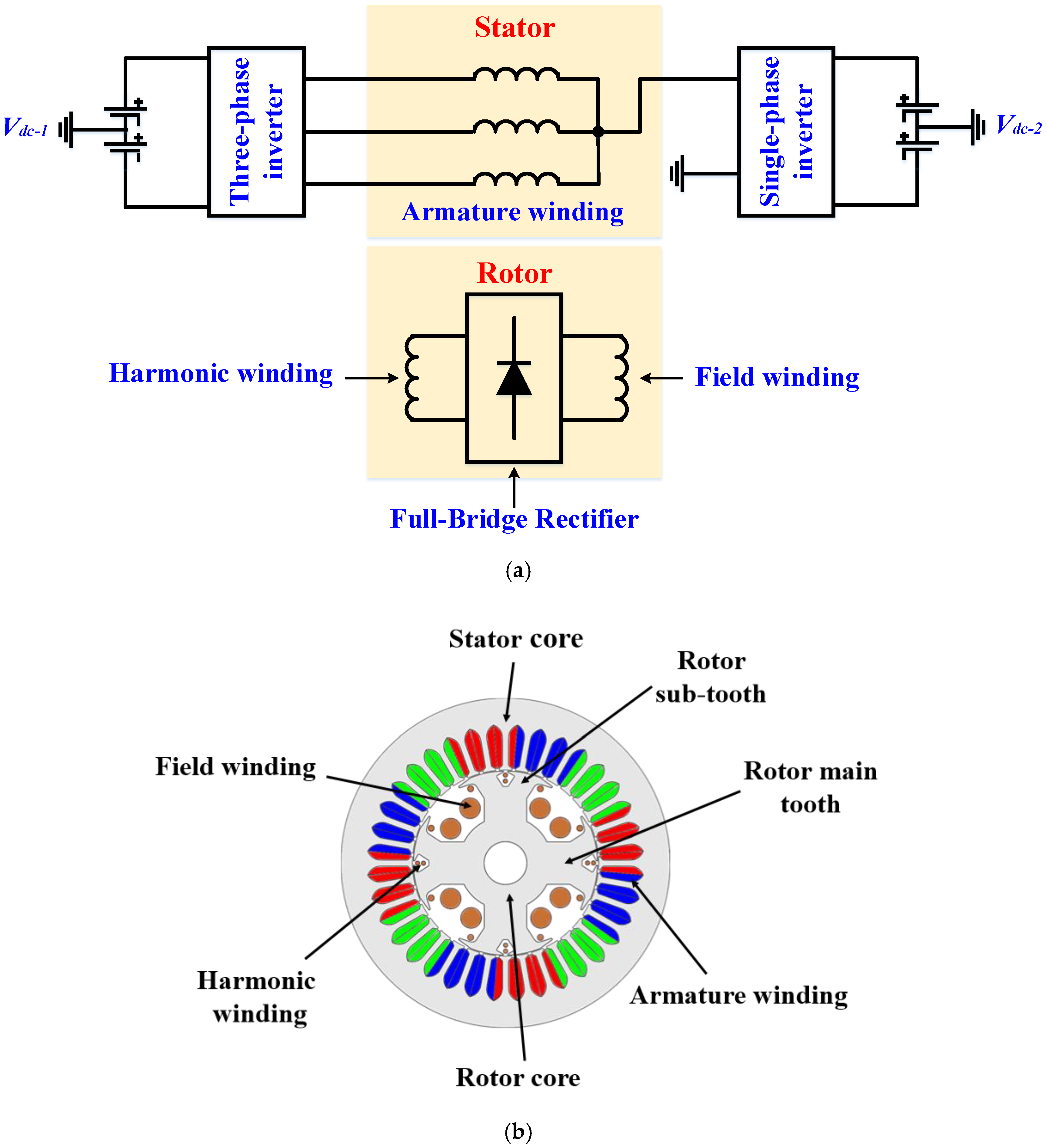
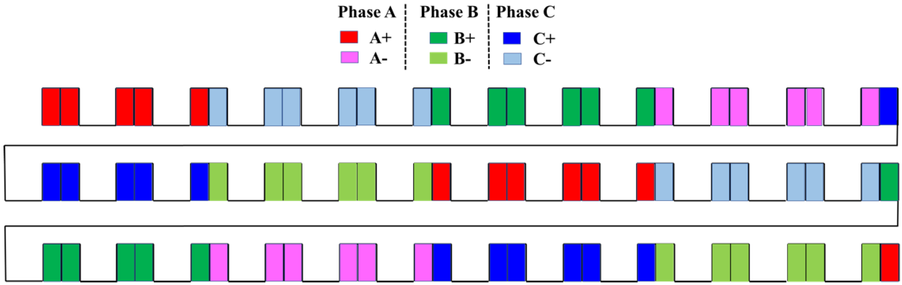
2.1. Proposed Topology
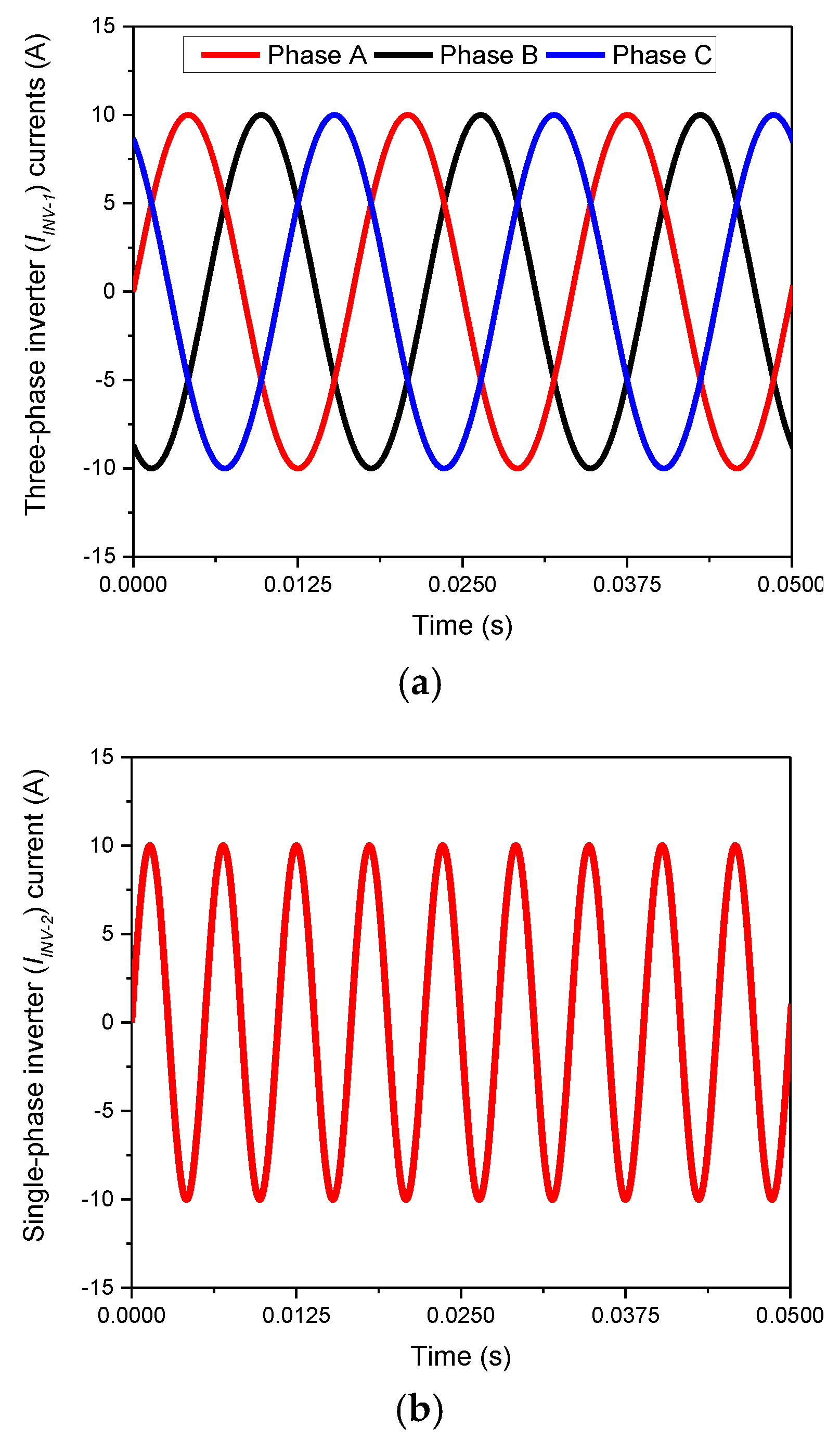
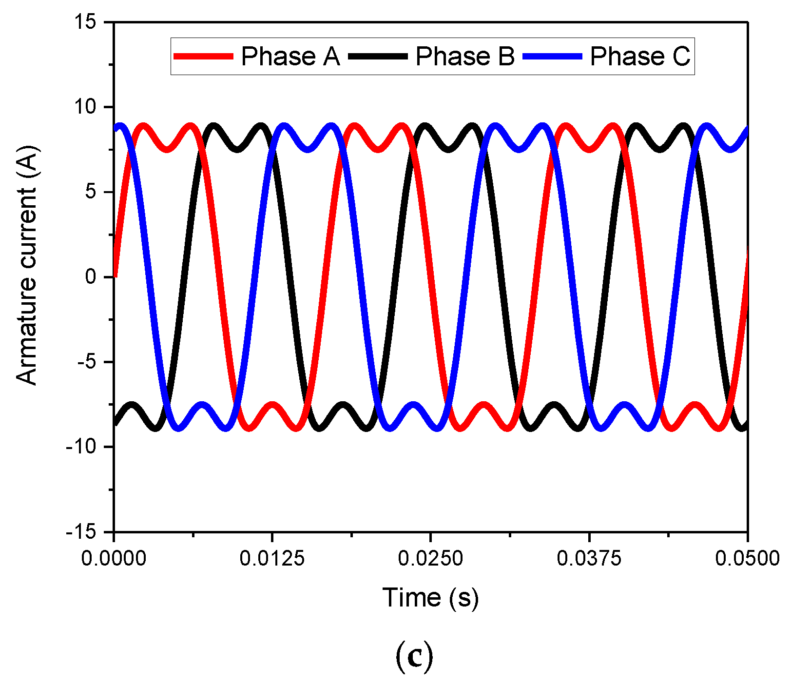
2.2. Operating Principle
3. Finite Element Analysis
4. Conclusions
Author Contributions
Funding
Conflicts of Interest
References
- Ayub, M.; Sirewal, G.J.; Bukhari, S.S.H.; Kwon, B.-I. Brushless wound rotor synchronous machine with third-harmonic field excitation. Electr. Eng. 2020, 102, 259–265. [Google Scholar] [CrossRef]
- Bukhari, S.S.H.; Sirewal, G.J.; Ayub, M.; Ro, J.-S. A New Small-Scale Self-Excited Wound Rotor Synchronous Motor Topology. IEEE Trans. Magn. 2020, 1. [Google Scholar] [CrossRef]
- An, Q.; Gao, X.; Yao, F.; Sun, L.; Lipo, T. The structure optimization of novel harmonic current excited brushless synchronous machines based on open winding pattern. In Proceedings of the 2014 IEEE Energy Conversion Congress and Exposition (ECCE), Pittsburgh, PA, USA, 14–18 September 2014; pp. 1754–1761. [Google Scholar]
- Bukhari, S.S.H.; Jawad, G.; Chachar, F.A.; Ro, J.-S. Dual-Inverter-Controlled Brushless Operation of Wound Rotor Synchronous Machines Based on an Open-Winding Pattern. Energies 2020, 13, 2205. [Google Scholar] [CrossRef]
- Memon, A.A.; Shaikh, M.M.; Bukhari, S.S.H.; Ro, J.-S. Look-up Data Tables-Based Modeling of Switched Reluctance Machine and Experimental Validation of the Static Torque with Statistical Analysis. J. Magn. 2020, 25, 233–244. [Google Scholar] [CrossRef]
- Khan, S.; Bukhari, S.S.H.; Ro, J.-S. Design and Analysis of a 4-kW Two-Stack Coreless Axial Flux Permanent Magnet Synchronous Machine for Low-Speed Applications. IEEE Access 2019, 7, 173848–173854. [Google Scholar] [CrossRef]
- Ali, Q.; Bukhari, S.S.H.; Atiq, S. Variable-speed, sub-harmonically excited BL-WRSM avoiding unbalanced radial force. Electr. Eng. 2019, 101, 251–257. [Google Scholar] [CrossRef]
- Ali, Q.; Lipo, T.A.; Kwon, B.-I. Design and Analysis of a Novel Brushless Wound Rotor Synchronous Machine. IEEE Trans. Magn. 2015, 51, 1. [Google Scholar] [CrossRef]
- Ayub, M.; Hussain, A.; Jawad, G.; Kwon, B.-I. Brushless Operation of a Wound-Field Synchronous Machine Using a Novel Winding Scheme. IEEE Trans. Magn. 2019, 55, 1–4. [Google Scholar] [CrossRef]
- Ayub, M.; Atiq, S.; Sirewal, G.J.; Kwon, B.-I. Fault-Tolerant Operation of Wound Field Synchronous Machine Using Coil Switching. IEEE Access 2019, 7, 67130–67138. [Google Scholar] [CrossRef]
- Ayub, M.; Bukhari, S.S.H.; Jawad, G.; Kwon, B.-I. Brushless wound field synchronous machine with third-harmonic field excitation using a single inverter. Electr. Eng. 2019, 101, 165–173. [Google Scholar] [CrossRef]
- Jawad, G.; Ali, Q.; Lipo, T.A.; Kwon, B.-I. Novel Brushless Wound Rotor Synchronous Machine with Zero-Sequence Third-Harmonic Field Excitation. IEEE Trans. Magn. 2016, 52, 1–4. [Google Scholar] [CrossRef]
- Yao, F.; An, Q.; Sun, L.; Lipo, T.A. Performance Investigation of a Brushless Synchronous Machine with Additional Harmonic Field Windings. IEEE Trans. Ind. Electron. 2016, 63, 6756–6766. [Google Scholar] [CrossRef]
- Yao, F.; An, Q.; Gao, X.; Sun, L.; Lipo, T.A. Principle of Operation and Performance of a Synchronous Machine Employing a New Harmonic Excitation Scheme. IEEE Trans. Ind. Appl. 2015, 51, 3890–3898. [Google Scholar] [CrossRef]


| Attribute | Value |
|---|---|
| Rated power | 2.5 kW |
| Speed | 1800 rpm |
| Stator outer/inner diameter | 177 mm/100 mm |
| Airgap | 0.5 mm |
| Rotor diameter | 99 mm |
| Shaft diameter | 23 mm |
| Machine poles/Stator slots | 4/36 |
| Rotor main teeth/sub-teeth | 4/8 |
| Harmonic and field winding number of turns | 9/150 turns |
| Stack length | 80 mm |
| Attribute | Value |
|---|---|
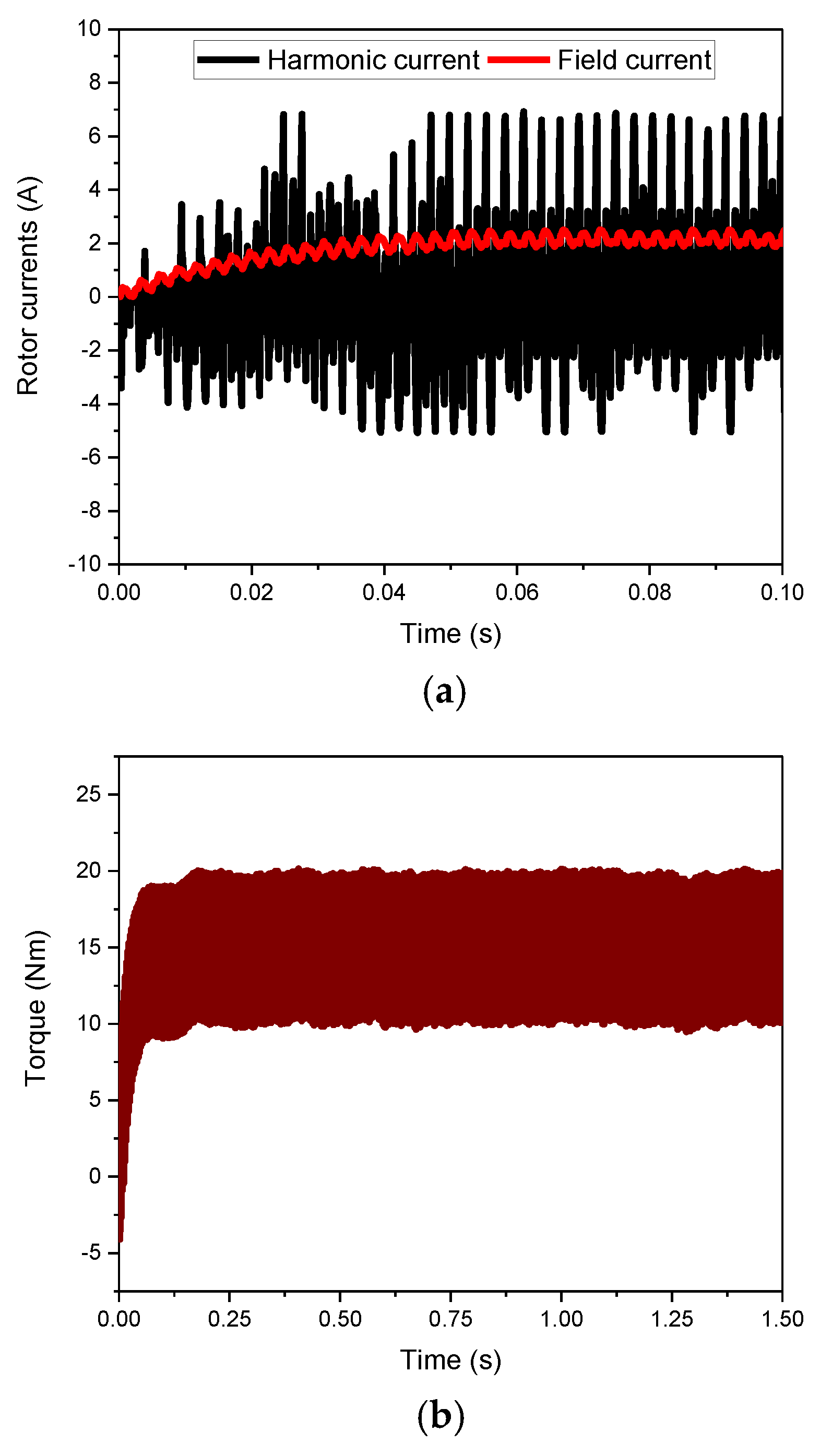
| Average Torque | 14.372 Nm |
| Torque ripple | 66% |
© 2020 by the authors. Licensee MDPI, Basel, Switzerland. This article is an open access article distributed under the terms and conditions of the Creative Commons Attribution (CC BY) license (http://creativecommons.org/licenses/by/4.0/).
Share and Cite
Bukhari, S.S.H.; Sirewal, G.J.; Chachar, F.A.; Ro, J.-S. Brushless Field Excitation Scheme for Wound Field Synchronous Machines. Appl. Sci. 2020, 10, 5866. https://doi.org/10.3390/app10175866
Bukhari SSH, Sirewal GJ, Chachar FA, Ro J-S. Brushless Field Excitation Scheme for Wound Field Synchronous Machines. Applied Sciences. 2020; 10(17):5866. https://doi.org/10.3390/app10175866
Chicago/Turabian StyleBukhari, Syed Sabir Hussain, Ghulam Jawad Sirewal, Faheem Akhtar Chachar, and Jong-Suk Ro. 2020. "Brushless Field Excitation Scheme for Wound Field Synchronous Machines" Applied Sciences 10, no. 17: 5866. https://doi.org/10.3390/app10175866