Article

Needle Transportable Semi-Automatic Hair Follicle Implanter and Image-Based Hair Density Estimation for Advanced Hair Transplantation Surgery

1
Daegu-Gyeongbuk Research Center, Electronics and Telecommunications Research Institute, Daegu 42994, Korea
2
Ohdae Metal Co., Ltd., Daegu 42984, Korea
*
Author to whom correspondence should be addressed.
Appl. Sci. 2020, 10(11), 4046; https://doi.org/10.3390/app10114046
Submission received: 7 May 2020 / Revised: 8 June 2020 / Accepted: 10 June 2020 / Published: 11 June 2020
(This article belongs to the Special Issue Implantable Medical Device)

Abstract

:
As the number of hair follicles transplanted in a patient is approximately 2000 or more, hair transplantation by a manual implanter requires a considerable amount of time and money and demands a great amount of patience and pain tolerance from both patients and surgeons. In addition, many surgeons frequently experience musculoskeletal disorders owing to the numerous simple repetitive motions of the shoulder and wrist during the procedure. Moreover, the results of the surgery may vary depending on the skill of the surgeon. Although the hair follicle extraction technology has advanced in recent years, the hair follicle transplantation technology still uses a simple hand-held implanter owing to the difficulty of transplanting hair follicles and hair. In this study, a needle transportable semi-automatic hair follicle implanter that can continuously transplant hair follicles is introduced to alleviate the inconvenience of the existing manual implanter. In the developed semi-automatic implanter, a plurality of needles, into which the hair follicles are inserted, are sequentially supplied from the needle supply magazine to the implanter body by the guide groove. The hair follicles in the supplied needles are transplanted to the scalp through the forward and backward movement of the needle gripper and driving motors. The developed implanter can transplant several hair follicles without any replacement, which can shorten surgery time and reduce the fatigue experienced by patients and surgeons. The effectiveness of the proposed implanter was verified through the results of animal and clinical experiments.

1. Introduction

Hair loss treatment includes medication and management treatment, electromagnetic field treatment, and hair transplantation. Among them, hair transplantation is adopted when the hair does not increase through other treatments or if the hair is innately deficient [1]. Hair transplantation refers to a surgical technique in which the hair of the posterior scalp, which is not affected by hormones, is extracted, separated into hair follicle (HF) units, and transplanted into a hair-deficient area of the scalp [2,3,4]. This minimally-invasive surgery is mainly used to treat hair loss in men. According to the International Society of Hair Restoration Surgery, the global market for hair transplantation has increased by 76% from 2006 to 2014 [5]. The total market size for hair transplantation surgery has increased 28% since 2012, from $1.9 billion USD in 2012 to $2.5 billion USD in 2014. Approximately 397,048 hair transplantation surgeries were performed worldwide in 2014, with 112,409 in the US.
Hair transplant surgery is classified into follicular unit transplantation (FUT) [3,6,7] and follicular unit extraction (FUE) [8,9,10,11,12], depending on how HFs are harvested. The FUT is known as the strip procedure, where a patient’s hair is transplanted in naturally occurring groups of 1–3 hairs, called follicular units (FUs) [7]. In the strip harvesting for the FUT, a surgeon harvests a strip of skin from an area with good hair growth in the posterior scalp, as shown in Figure 1a. The excised strip has the size of approximately (1–1.5) × (15–30) cm. While closing the resulting wound, nurses begin to dissect individual FU grafts, which are small, naturally formed groupings of HFs, from the strip [8]. They carefully remove excess fatty and fibrous tissue while avoiding damage to the follicular cells that will be transplanted.
In the FUE, individual FUs, each containing 1–4 hair strands, are extracted under local anesthesia [10]. This micro removal typically uses tiny punches with a diameter between 0.6 and 1.0 mm, as shown in Figure 1b. The surgeon then uses very small micro-blades or fine needles to puncture the extraction sites to receive the grafts and place them in a predetermined density and pattern in the target area [11]. Although the FUE has restrictions on patient candidacy, is considered to be more time consuming, and is dependent on the skill of the surgeon, the FUE has many advantages, including a small donor wound, less pain, and a slender graft without extra surrounding tissue. For safe transplantation of HFs, a manual implanter is used in the both FUE and FUT [12]. An improved procedure for FUE with a motor-driven handpiece, the powered FUE (P-FUE) was introduced in the recent years [13,14]. Since the P-FUE uses pneumatic pressure to extract the HFs, it eliminates the need for touching the follicles with forceps during harvesting. Recently, the ARTAS robotic system was developed to harvest FUs automatically using imaging technology and robotics [15,16,17,18,19]. The ARTAS system automated traditional HFs harvesting method by FUE using accuracy image-guided robotic techniques, as shown in Figure 1c. However, it was not widely used owing to the rather high transection rate of FU in actual use.
As mentioned previously, various HF extraction methods have been proposed. However, the only tool developed for transplanting HF is the manual implanter [20,21,22]. Further, an equipment for HF transplantation is very difficult to develop because HF transplantation comprises more complex operations when compared to HF extraction. The most representative manual implanter is the KNU implanter [21,23,24]. There are three different sizes of the KNU implanter: S, M, and L. The S, M, and L types are used for one, two, and three hair units, respectively. Figure 1d shows the loading of the HFs. The procedure involves inserting the HF tissue inside the needle of the manual implanter using forceps, and applying the hair to the needle groove. Manual implanters are known to have a higher HF survival rate compared to other simple transplantation methods that place HFs in punctures made using micro-blades or fine needles.
Although the manual implanter is the most commonly used device in hair transplantation, it has a few fundamental problems, as shown in Figure 2. First, the long surgery time, caused by its structure, leads to much fatigue for both surgeons and patients. When the surgeon performs the transplant surgery, the nurse loads a HF in the needle of the manual implanter at the rate with which the surgeon transplants the HF. Second, musculoskeletal disorders are more likely to occur in surgeons due to the numerous simple repetitions of movements of the shoulder and wrist. This also relates to the longevity of the career of the surgeon. Third, a difference between the number of hairs transplanted per hour and HF engraftment rate may exist owing to varying surgical abilities of each surgeon. Fourth, the needle strength of the manual implanter is maintained for a specific patient. Consequently, the manual implanter is discarded after surgery without being reused. Since the needle is attached to the body of the manual implanter, the implanter cannot be reused even when only the needle is deformed. This results in higher surgical costs, in addition to continuous accumulation of other charges.
On 10 May 2014, at the Korean Society of Hair Transplantation, a questionnaire was conducted on an automated hair transplantation device for a hair transplant clinician as shown in Figure 3. The total number of responses was 94, and 62% and 41% of respondents had clinical experience in hair transplantation for 3 years and 5 years or more, respectively. As a result of the survey, the proportion of respondents using manual implanter in the method of transplanting hair was 87.2%, the time for transplanting 3000 HFs was 4~5 h, and the intention to use an automated hair transplant device was 84%. Through the survey results, many doctors demand the need for an automated hair transplantation device, and if it is commercialized, it is judged that it will be able to create a sufficient market.
In the current hair transplant surgery, a minimum of 2000 HFs are implanted in one patient. In each transplant, the surgeon executes a series of movements such as gripping, moving, aiming, transplanting, and in situ movement of a manual implanter. Repetition of these actions directly causes fatigue. Although several advanced devices for continuously extracting HFs, such as P-FUE and ARTAS, have been invented, devices for continuously transplanting HFs have not been developed yet. This is because the operation of the HF transplant is much more sophisticated and complicated than the HF extraction. To address the aforementioned problems, this study introduces a needle transportable semi-automatic implanter that can continuously transplant HFs without any replacement. The proposed implanter was designed to replace the repetitive motions of the surgeon when using the manual implanter with the replacement of a magazine equipped with multiple needles. Moreover, as the number of implant needles inserted into the magazine of proposed implanter increases, the surgical fatigue experienced by the surgeon and the patient, caused by the existing the manual implanter, decreases. In the proposed implanter, the needle part used in the manual implanter is independently present and, thus, disposable. Consequently, the cheap disposal cost of the needle can replace the expensive disposal cost of the manual planter. The semi-automatic implanter can radically shorten the surgery time because of the increase in the speed of the drive motor and continuous needle supply by the needle supply magazine (NSM). Considering the surgeon’s experiences and preferences, the control software also enables a more precise surgery by adjusting the penetration depth and forward (or backward) speeds of the needle and the rod.

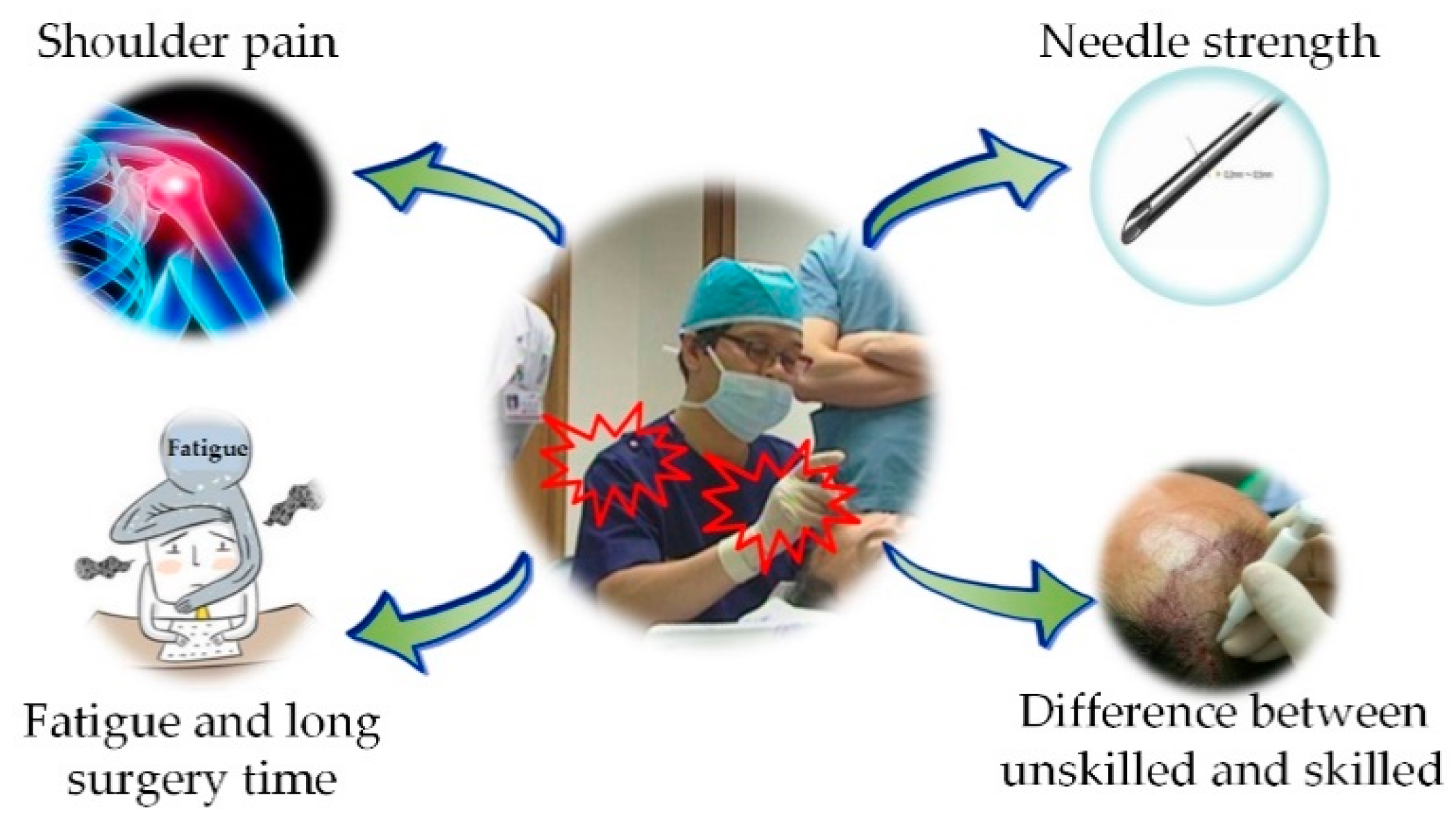
2. Background and Motivation

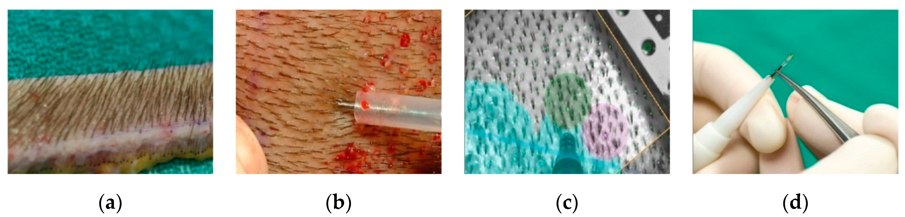
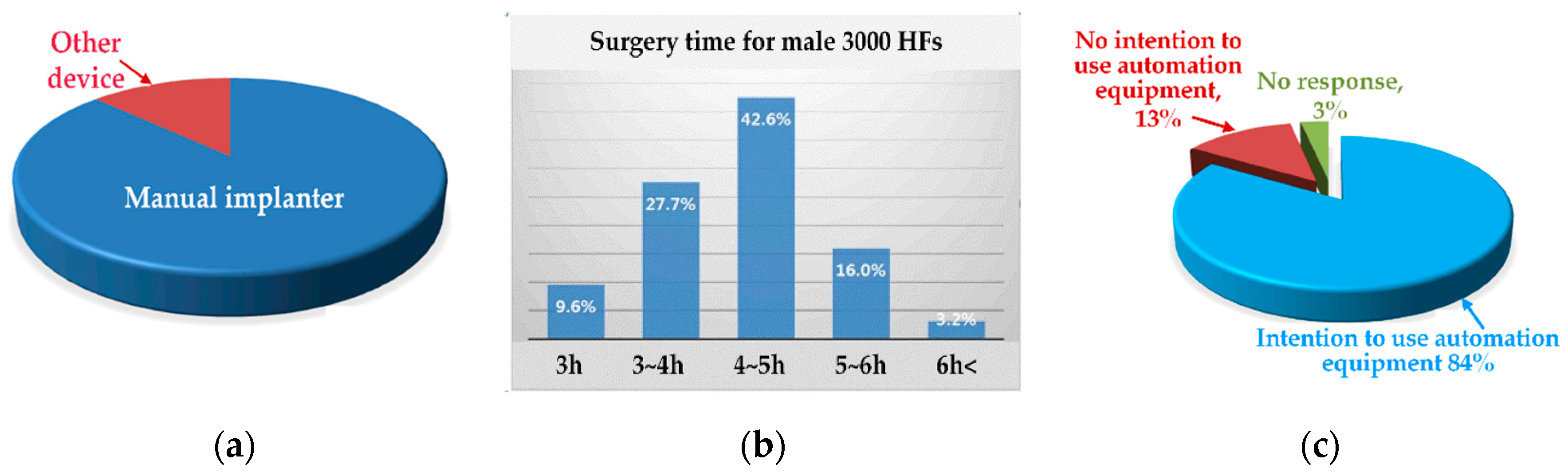
2.1. Current Hair Transplant Procedure

Figure 4 shows the results of behavioral analysis of a professional, with 15 years of hair transplantation experience, transplanting a single HF. The overall procedure for transplanting a HF consists of catching and moving the implanter, adjusting the implanter, aiming at the transplant site, inserting the needle into the scalp, pressing the rod for transplantation, removing the implanter, and moving the implanter in situ. Please note that, in this analysis, more than half of the total procedure time is spent on the tool (implanter) change and movement. This analysis shows that continuous HF supply can theoretically reduce the conventional surgery time from 4.5 s to less than 2 s.

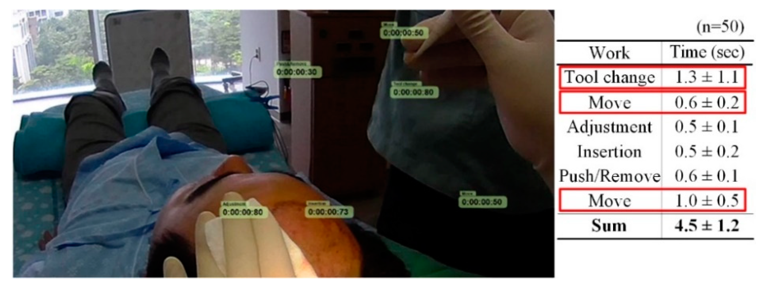
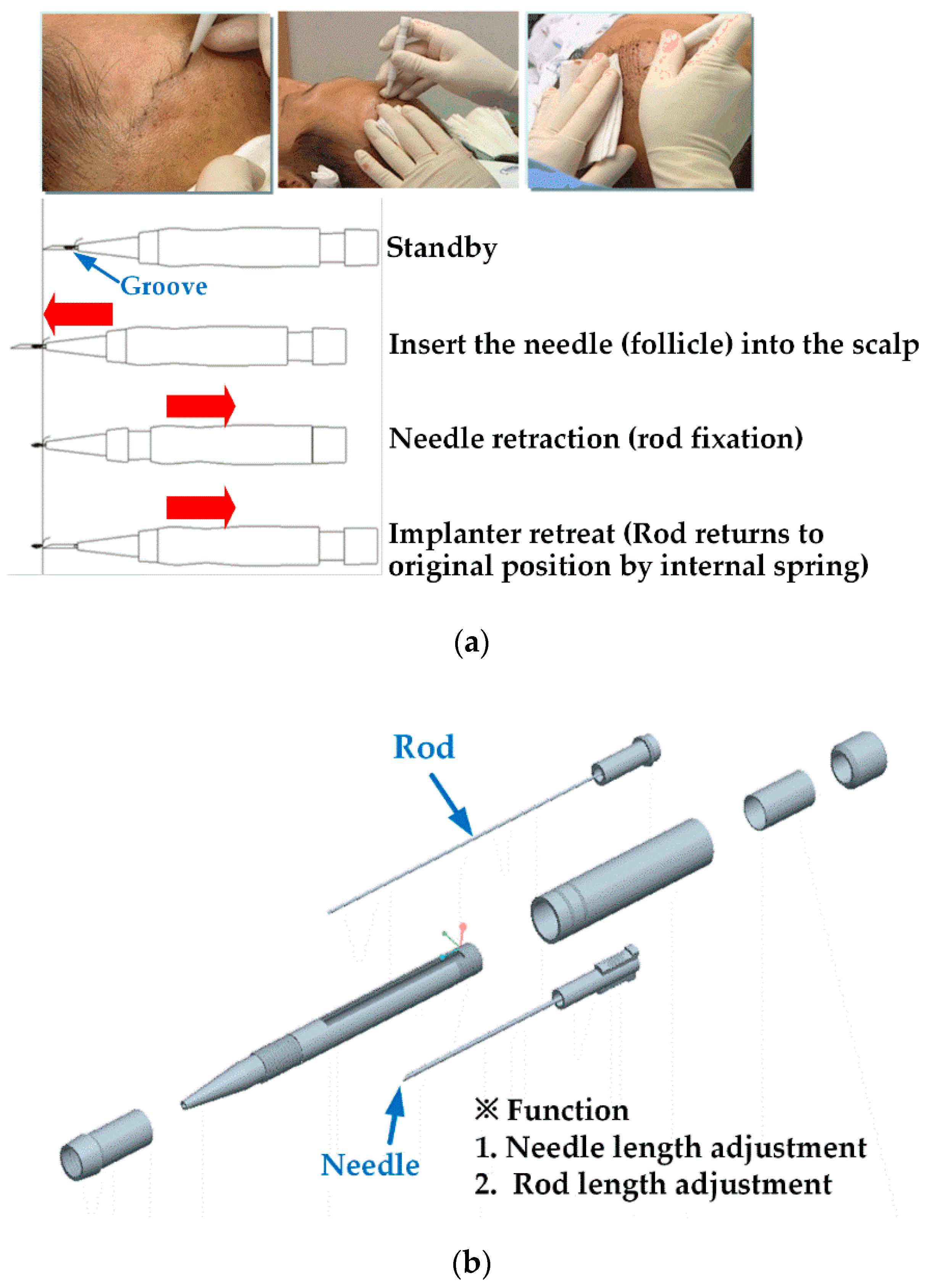
2.2. Operation Principle of the Manual Implanter

The operation sequence and configuration of the manual implanter are shown in Figure 5. This analysis was performed on the KNU implanter [21,23]. A FU is placed onto the needle of the implanter using forceps. The surgeon inserts the needle into the skin at the desired angle and pushes the rod. The needle is then automatically retracted, leaving the hair graft sprucely tucked under the skin [25]. The small and long guide grooves on the housing hold the hair graft in place while the needle is retracted. The guide groove can make the epidermis level between grafts and recipient skin the same to ensure that the exit point of each hair looks natural.
To automate the operation of the manual planter, the movement of the needle and rod should be clearly defined. The needle had an outer and inner diameter of 1 mm and 0.8 mm, respectively, and the rod has an outer diameter of 0.6 mm.

3. Materials and Methods

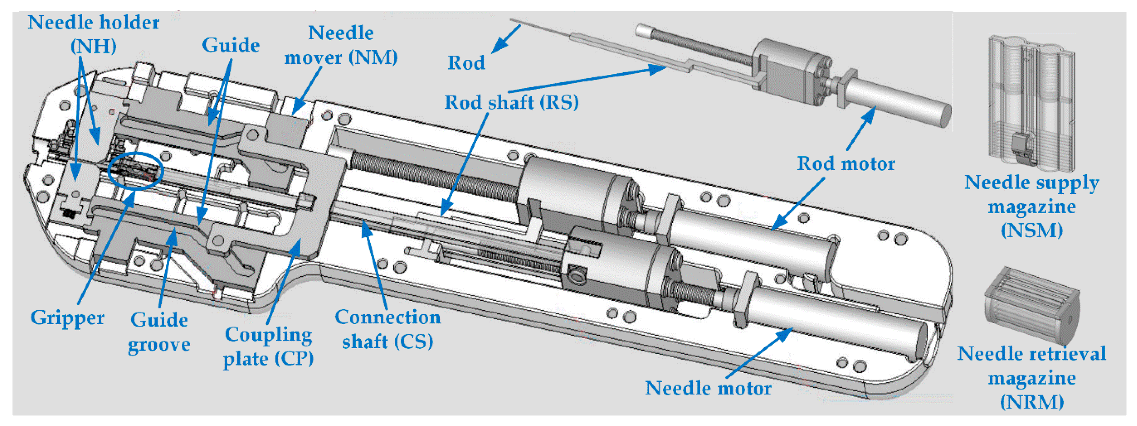
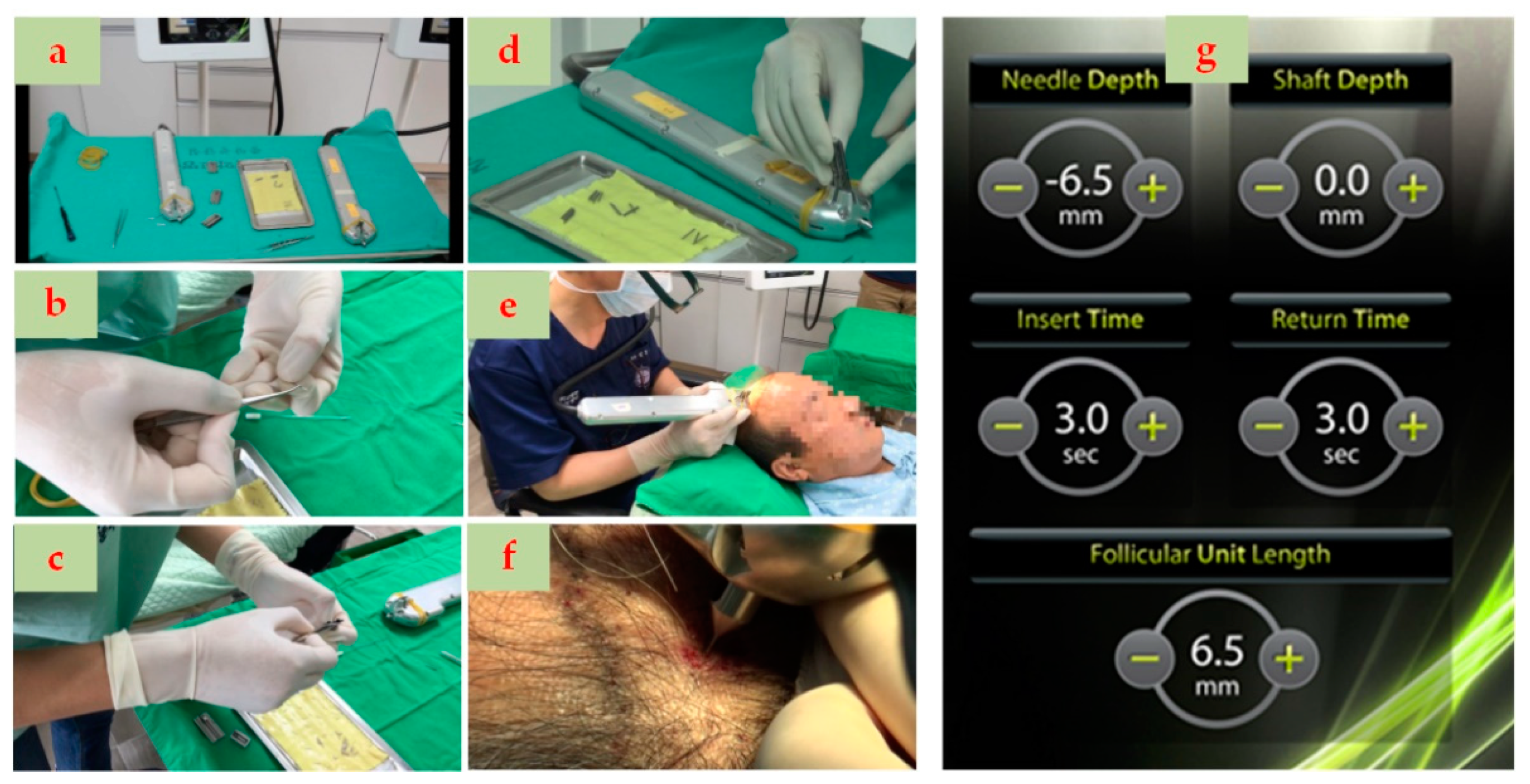
3.1. Structure of the Proposed Semi-Automatic Implementation

The structure of the semi-automatic implanter developed in this study is shown in Figure 6 [26]. The NSM is installed on the housing and sequentially supplies a plurality of needles containing HFs. The needle in the NSM is the same as the needle mounted on the manual implanter, and its length is 1.8 cm. After an HF is implanted, an empty needle is returned to the needle retrieval magazine (NRM). The needle mover (NM) moves a needle from the NSM to the center of the nozzle. The needle motor causes the needle to protrude out of the nozzle for transplantation. The rod motor supports the HF in the protruded needle.
The NM includes a pair of needle holders (NH) positioned to face each other, and a pair of guides guiding each of the NHs. The guides have grooves, including inclined and parallel portions on upper surfaces. The gripper connected to the end of the connection shaft (CS) grips the needle held by the NH. The coupling plate is connected to the NM guides by the CS. When the CS moves forward, the gripper grips the back end of the needle aligned by NH and NM. The needle then protrudes out of the nozzle for transplantation.

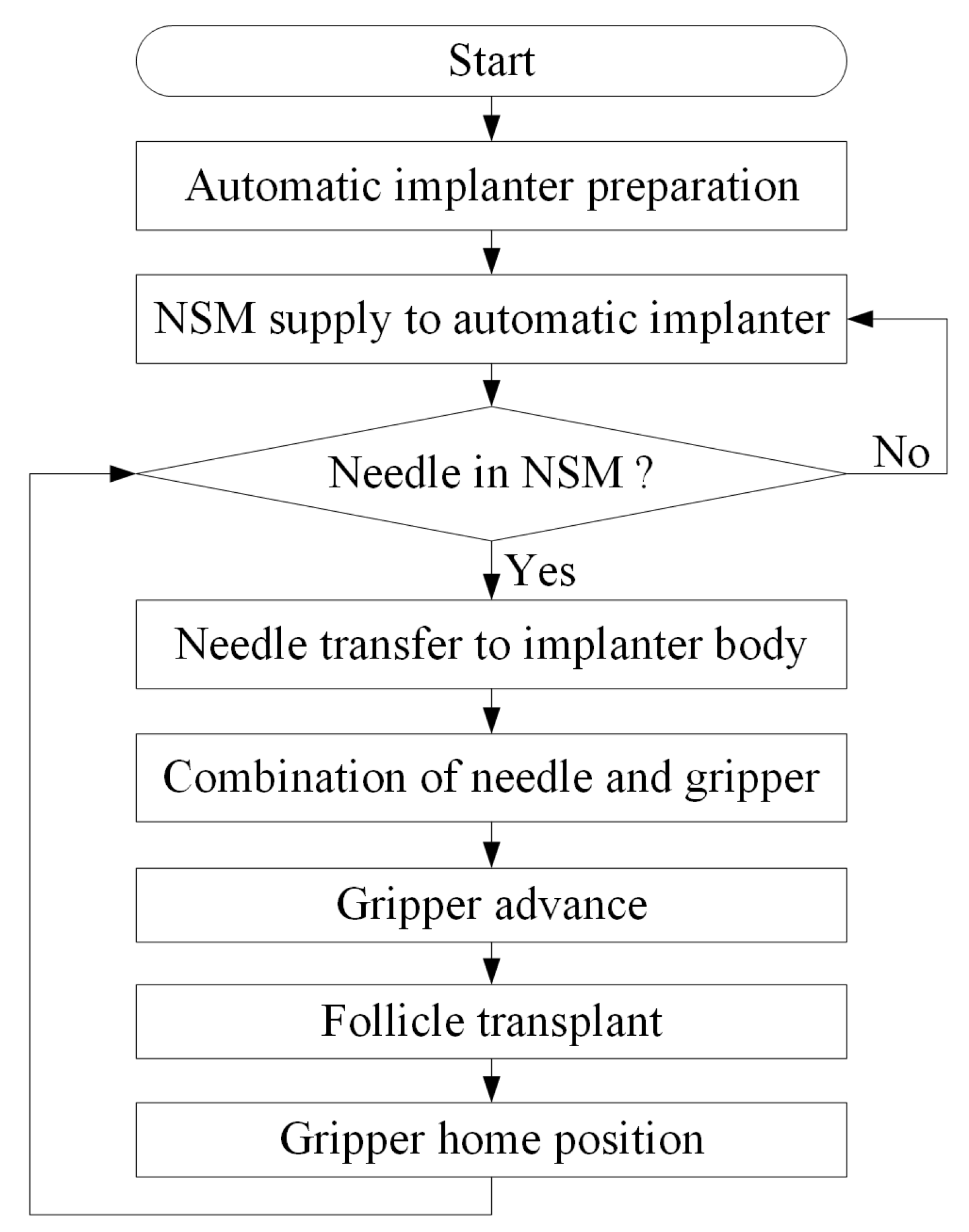
3.2. Operation Flowchart of Continuous Needle Supply

Figure 7 shows the operation flowchart for continuous needle supply and HF transplantation in the proposed semi-automatic implanter. When the NSM equipped with multiple needles is combined with the semi-automatic implanter body, the needles are sequentially supplied to the needle gripper. A single HF transplant is performed through the forward and backward movement of the needle gripper. After all the needles in NSM are used, a new NSM is supplied.

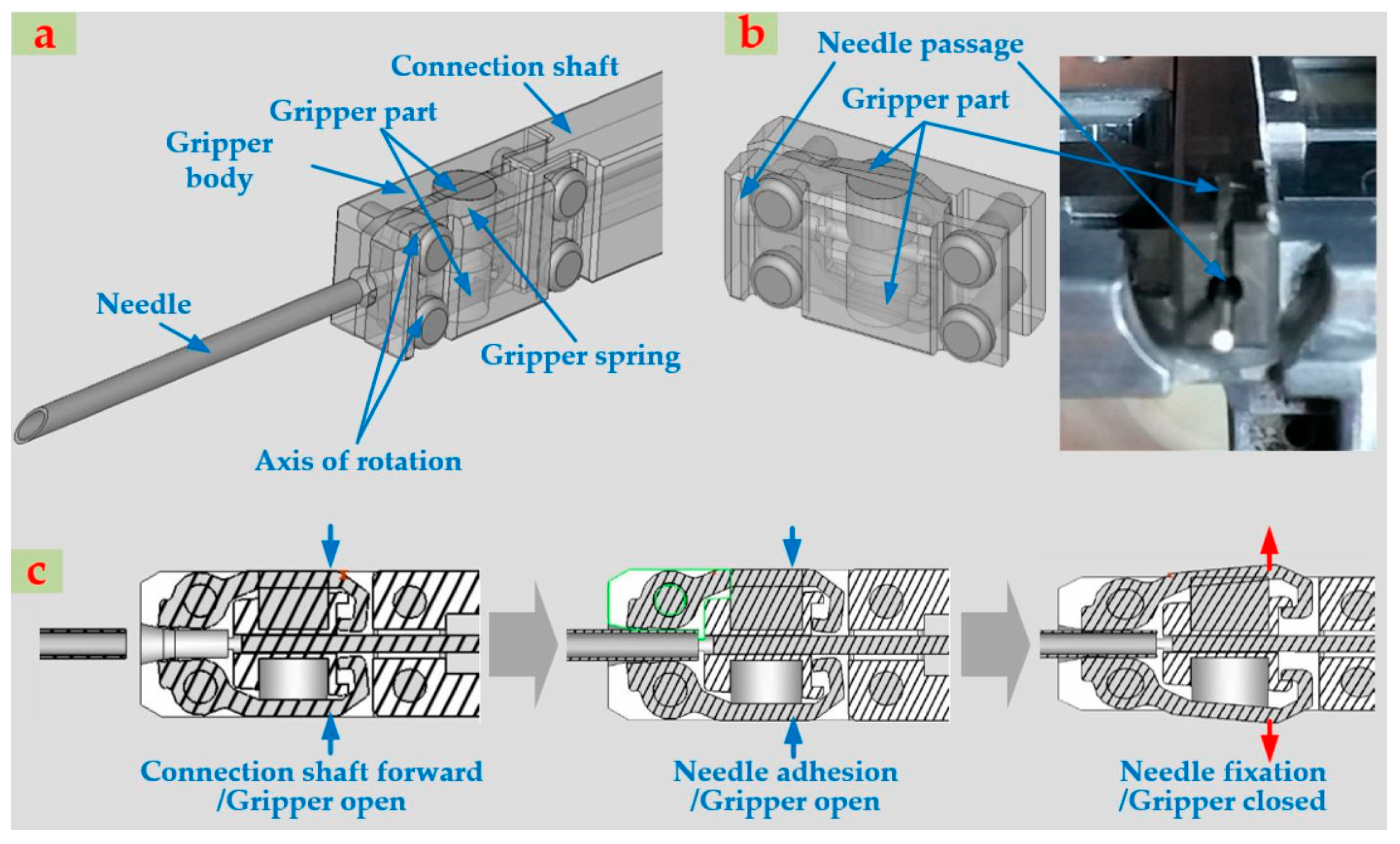
3.3. Grip and Release of Needles by Gripper

Figure 8 shows the grip and release states of the gripper during the forward and backward movement of the CS for HF transplantation. The needles aligned with the center of the nozzle by the CS and guide are engaged using the gripper, and then the gripper parts directly hold the aligned needle. The gripper is opened or closed by compression and expansion of the gripper spring on the rotation axis. As the CS moves forward, the gripper parts are pressed (pushed) by the protrusions inside the housing and the compression of the inner gripper spring at the aligned needle position. This makes the gripper open, as shown in Figure 8. In this open state of the gripper, the needle enters it (needle adhesion state). Thereafter, the gripper with the needle moves forward and passes through the protrusions inside the housing. The gripper part then grips the needle by expanding the gripper spring (needle fixation state). Then, from this time until they return to this position after implantation, the gripper and the needle work as one part.

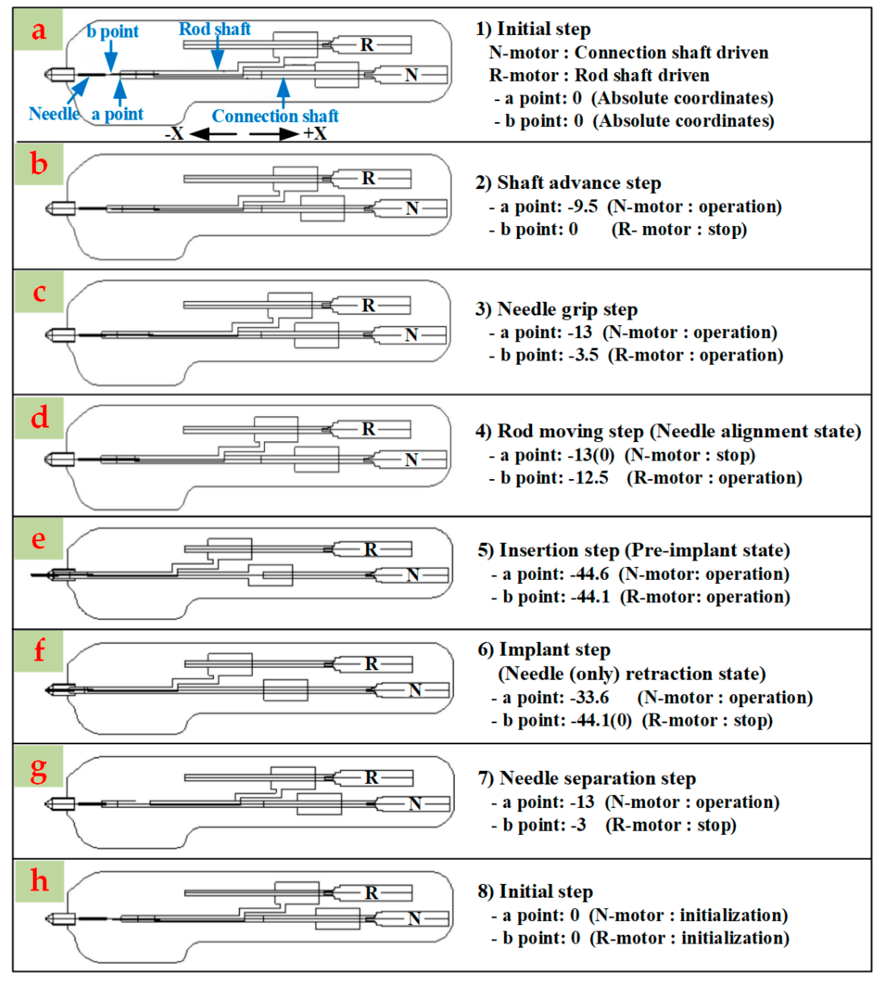
3.4. Automation of the Transplantation Procedure

To automate the transplantation procedure, the movement of the needle and the rod described in Section 2.2 should be defined quantitatively. As shown in Figure 9, the movement of the needle and the rod is divided into seven steps. The numerical unit in Figure 9 is millimeter. The CS and rod shaft (RS) responsible for the forward and backward movement of the needle and rod are driven by a needle motor (N-motor) and rod motor (R-motor), respectively. In the initial step (Figure 9a), the a and b points represent the initial front-end positions of the gripper and rod, respectively, in absolute coordinate values. The CS is first advanced by the N-motor (Figure 9b) so that the gripper is located at the back end of the aligned needle. The RS is then moved forward by the R-motor, and the gripper moves forward to grip the needle (Figure 9c). The N-motor then stops temporarily while the R-motor continues moving forward, and the rod is inserted into the needle (Figure 9d). Then, the needle and rod are advanced together and inserted into the scalp (Figure 9e). Thereafter, while the rod remains stationary (the R-motor the momentary stops), the needle is retracted by the retraction of the N-motor, leaving the HF in the scalp (Figure 9f). After HF transplantation, the N- and R-motors work together to retract the needles and rods together. The rod is retracted faster than the needle so that the rod can escape inside the needle before the needle is released from the gripper. After the needle reaches the initial position where it was picked up by the gripper, the N-motor reverses while the R-motor stops temporarily so that the gripper and the needle are separated (Figure 9g). The needle removed from the gripper is gripped by the support parts. Thereafter, the N- and R-motors return to their initial position (Figure 9h). These strokes of the semi-automatic implanter operate according to the 18 mm length of the needle used for the manual implanter. Although driving motors work very accurately, micro-errors may accumulate with each revolution. Consequently, the homing mode is executed to return to reset the implanter after a certain number of implantations [27].

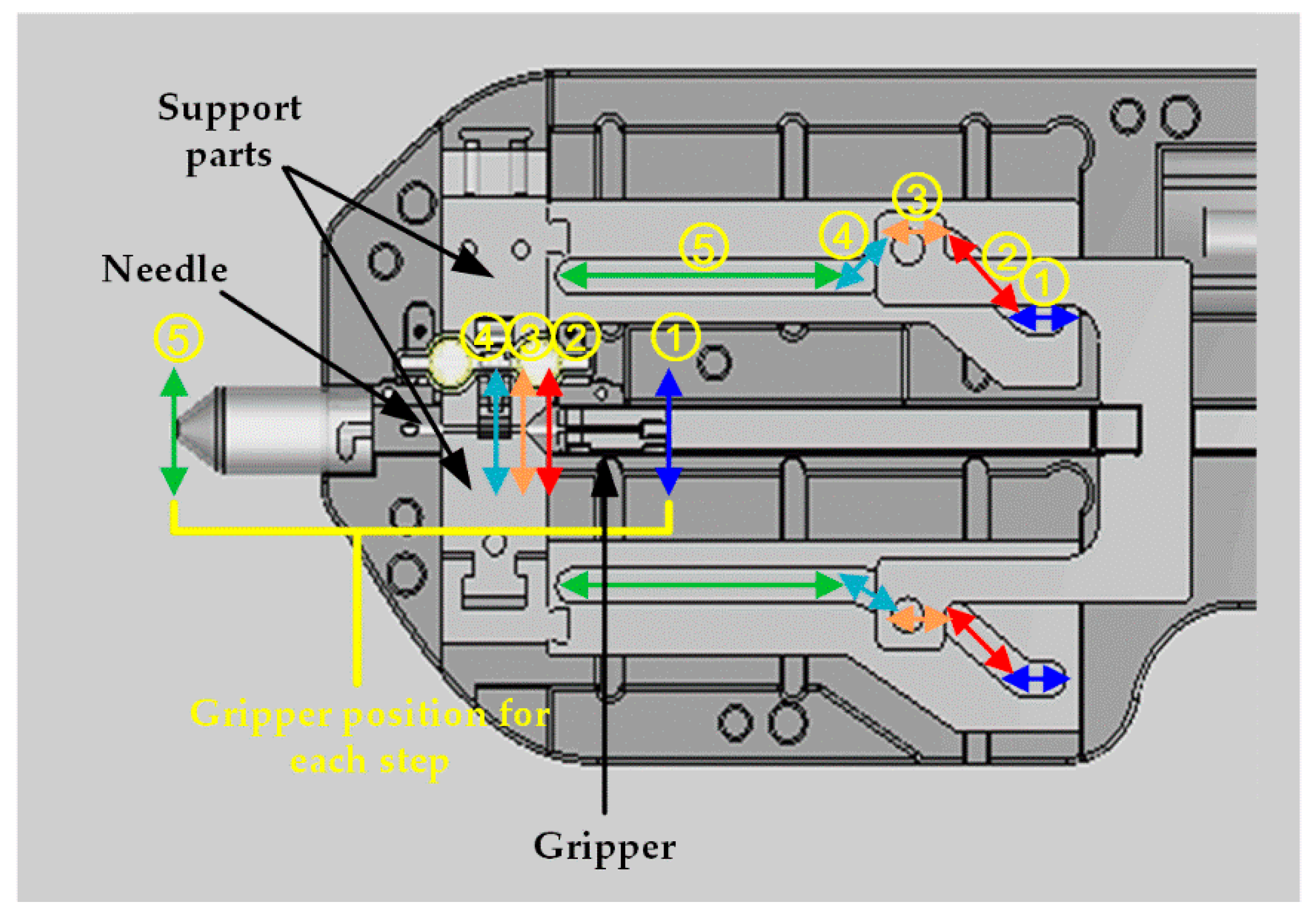
3.5. Guide Structure for Needle Transfer

The guide structure for the needle to be transported from the NSM and NRM is shown in Figure 10. The needle is transported by five separate sections of the guide groove, where the position of the gripper is indicated, in the guide. First, the function of each section in the forward stroke is explained. In the first section, the gripper waits in (or returns to) the initial position (1). In the second section, the support parts align the needle from the NSM to the center of the nozzle (or from nozzle center to the opening of the NRM) (2). The support parts also move the needle from the nozzle center to the inlet of the needle retrieval magazine. In the third section, the gripper grips (or un-grips) the needle, which carried by the support parts (3). In the fourth section, the groove narrows (or widens) to allow the gripper to move forward (or backward), opening (or closing) the support parts (4). In the fifth section, the gripper mounted needle is advanced for implantation and inserted into the scalp (5). The gripper mounted needle moves backward after transplantation.
The description in parentheses indicates the functions in reverse stroke. In Section 5, the needle after transplantation retracts from the scalp. As the groove widens in Section 4, the support parts constrict to grip the needle attached to the gripper. In Section 3, the support parts grip the needle while the gripper releases the needle. In Section 2, the support parts transfer the needle from the nozzle center to the opening of the NRM. In Section 1, the gripper returns to its initial position.

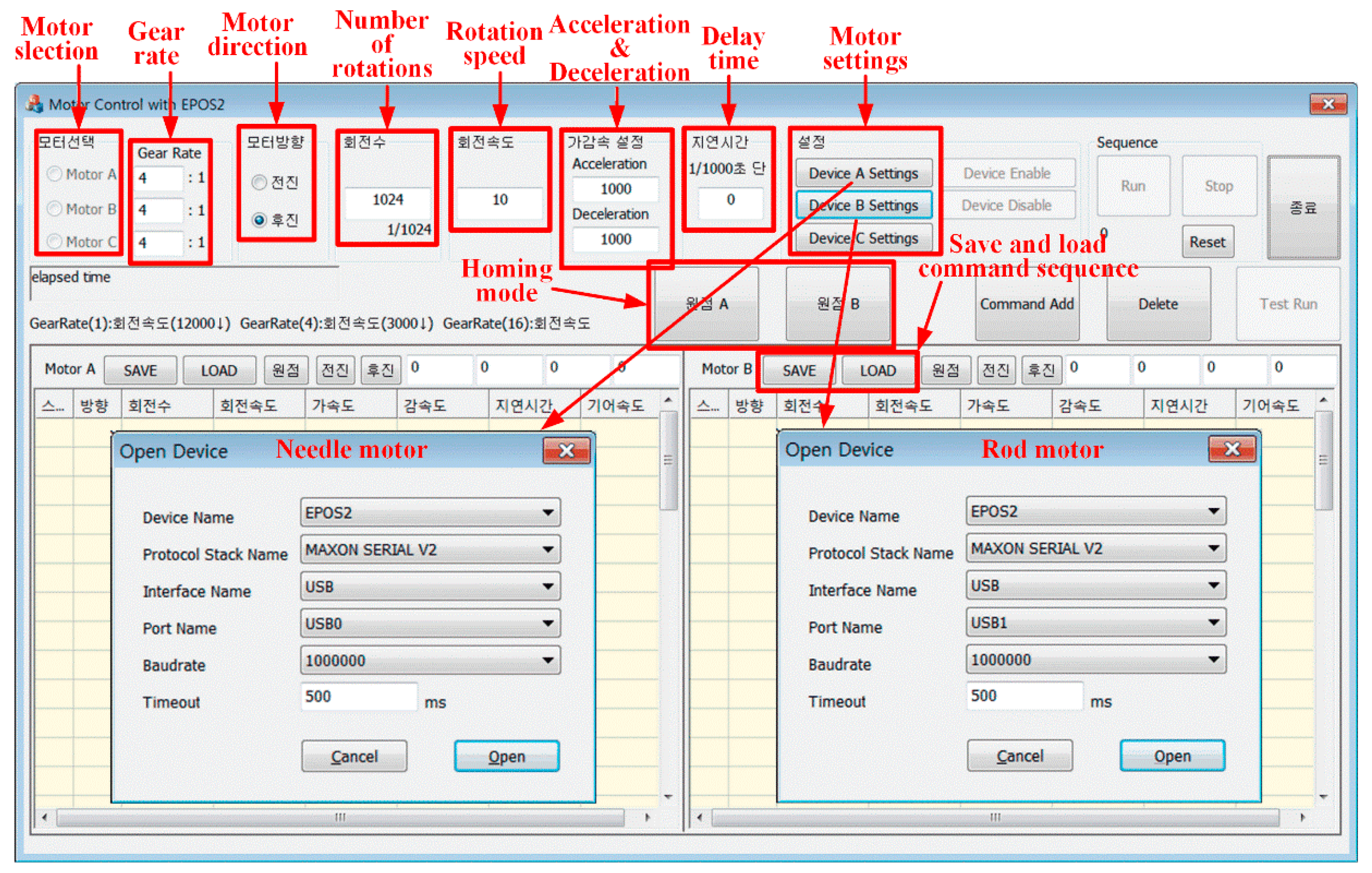
3.6. Driving Environment

The driving environment of the semi-automatic implanter is shown in Figure 11. To drive the needle (or gripper) and the rod, two Maxon DCX10L motors are used in Figure 11a, and a motor encoder is connected to each motor for driving them. The volume of the semi-automatic implanter is 257.9 × 59.8 × 36 mm and can be gripped with one hand. For the driving experiment, a number of implanting needles were inserted in the NSM. At the transplant, the needle and rod advance into the scalp, and then the HF is transplanted by the retraction of the needle while the rod is fixed; this moment of transplantation is shown in Figure 11b. The HF transplantation ability of the semi-automatic implanter was tested using artificial scalps with a hardness of 10 and 20, as shown in Figure 11c.
The movement of the needle and the rod of the semi-automatic implanter is based on the operating principle of the existing manual implanter, which leaves the HF inside the needle in the scalp. The developed motor control program using the EPOS2 digital positioning controller [27] is designed to set the motor gear ratio (4:1), direction, number of rotations, rotation speed, and acceleration and deceleration of respective motors for each transplant stroke, as shown in Figure 12.
The motor control program currently supports three motors, but it only uses two for the semi-automatic implanters. It has a selectable gear ratio and can set the rotation speed, acceleration and/or deceleration speed, and delay time. Since the motor encoder signal is 1024/cycle, the speed setting supports a resolution of 1/1024. The motor control program also has a homing mode function when both motors stop working. Its command comprise rotation direction, number of rotations, speed of rotation, acceleration, deceleration, delay time, and gear ratio. In addition, it can store an entirely new command or call up an existing command. Each motor is configured with a USB port interface with a baud rate and timeout of 106 and 500 ms, respectively.
The characteristics of the motor control program are as follows:
  • Initially, the driving motor is homed by the motor control EPOS2 program.
  • The transplant speed is adjusted by the setting of the number of rotations, rotation speed, and acceleration and/or deceleration of the needle motor and the rod motor.
  • The range of the rotation speed of the driving motor (DCX10L) is 0–32,256 rpm; the rotation speed for each transplant stroke can be changed according to the surgeon’ s preference.
  • Both motors operate at 1350 rpm by default. However, in the case of the rod motor, the rotation speed is 1350 rpm or more in two strokes: the insertion of the rod into the needle when moving forward (the fourth stroke) and the rapid release of the rod out of the needle when moving backward (the sixth stroke).
  • The motor-related setting values are entered in the order of movement of the needle and rod described in Section 3.4, but they can be adjusted within the confidence error.
Table 1 shows the setting value of each motor per transplant stroke. This setting value was based on the operation sequence of the needle and the rod of the semi-automatic implanter shown in Figure 9.

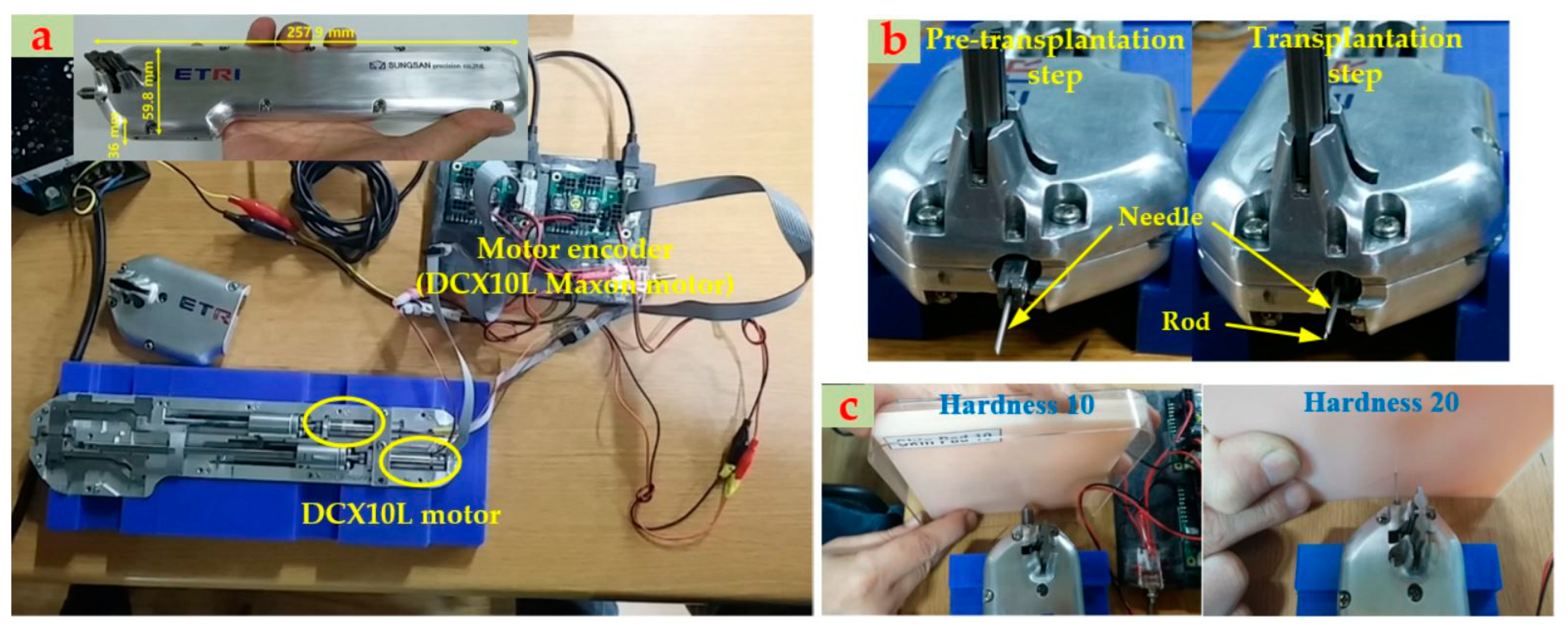
3.7. Item Approval of the Medical Device

The apparatus and controller of the developed semi-automatic implanter system was verified for electrical–mechanical and electromagnetic-wave safety by the Korea Compliance Testing Laboratories (KCTL) [28] and Korea Testing Certification [29]. The performance of the semi-automatic implanter was evaluated through the following:
  • Performance testing of the semi-automatic implanter by the KCTL
  • Performance testing of the needle used in the semi-automatic implanter by the Korea Testing Laboratory [30]
  • Biological stability (dermal reaction) test of the needle by Korea Conformity Laboratories [31] and
  • Needle asepsis (sterilization validation) and needle validation test by Greenpiatech incorp [32].
The suitability of the medical device technical documentation was certified by the Korea Testing & Research Institute (KTR) [33], and the grade-2 medical device manufacturing certification of the hair transplantation device was approved by the Medical Device Information & Technology Assistance Center [34]. The certificate of good manufacturing practice was approved by the KTR and Daegu Regional Korea Food & Drug Administration [35].

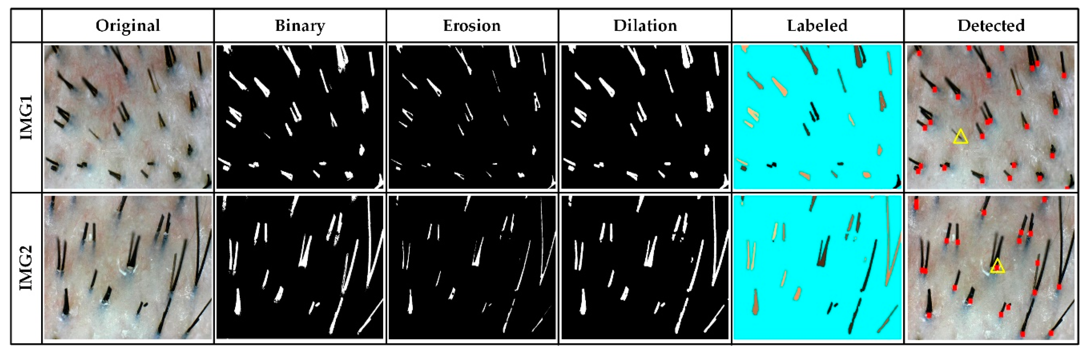
3.8. Image Processing for the Estimation of Hair Root and Hair Density

The estimation of hair root and density provides a surgeon with statistical information about the hair condition of a patient. It informs a surgeon and the patient about the amount of hair that can be harvested in a donor site during hair harvesting. In addition, the estimation of hair root and density can tell the density of the hair implanted to a recipient site during hair transplantation. This hair information of the patient allows a surgeon to perform more strategic surgeries. The most important and basic information for understanding hair condition is to estimate the position of hair roots in a hair close-up image obtained by a camera. In an image of the posterior scalp, the HF and hair exist in the lower and upper part of an image, respectively. For pixel indices, the row increases downward, while the column increases to the right. The obtained close-up RGB image is converted into a gray image, and the gray image is converted into a binary image to classify the skin and hair regions. Among morphological operators, erosion and dilation operations are applied to remove noise and improve the hair region of the binary image classified into the skin and hair region. A disk shape with a radius of 5 (strel disk radius in MATLAB 2019) was used as a structuring element for the operations. Each hair region has been assigned with labels, which were classified in the binary image. To exclude noise and unintended particles, if a number of any label is less than 0.025% of the size of the input image, the label is excluded from the hair regions. For example, the label set Lh for the hair regions is defined by Lh = {L1, L2, …, Lp}, where p is the maximum label, that is, the number of hair regions. The hair root is then defined as the position of the label with the largest row position value in the same label region of each hair region. If there are multiple column position values for the row position of a hair root, the average position of the column position values is defined as the column position of the hair root. Finally, the density of the hair is calculated by the number of hair roots per centimeter square. The simulation results for the hair root detection are described in Section 4.3.

4. Results

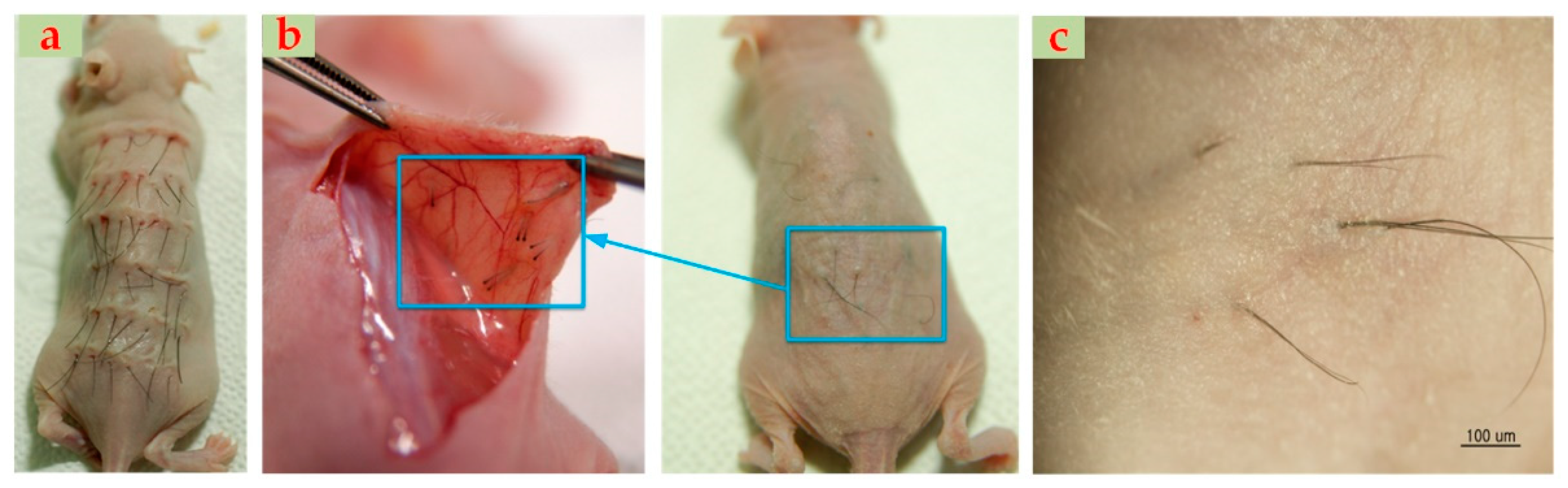
4.1. Animal Experiment

Animal experiments were performed using nude mice to compare the performance of the semi-automatic implanter and the existing manual implanter, as shown in Figure 13. The nude mice are immune-deficient and do not cause rejection of transplanted HF. In this experiment, human HFs were implanted in nude mice to compare the engraftment rate difference between the semi-automatic implanter and the manual implanter. Using the semi-automatic implanter and manual implanter, HFs obtained during surgery are transplanted to the back of the nude mouse. The transplanted hairs fall out in a month, and then 2 months later, new HFs are formed [36]. The difference in engraftment rate was verified by measuring the number of HFs regrown 4 months after transplantation.
In the back of four nude mice, a total of 34 and 36 HFs were transplanted by the semi-automatic implanter and manual implanter, and 33 and 25 HFs were grown, respectively, as shown in Table 2. The engraftment rates for the semi-automatic implanter and manual implanter were 97% and 70%, respectively. The small number of mice and HFs makes it difficult to determine the statistical significance of the two devices. Nevertheless, the experimental results show that the engraftment rate of the semi-automatic implanter is not lower than that of the manual implanter. In the comparison experiment of the engraftment rate of human HFs using nude mice, semi-automatic implanters showed no difference in the engraftment rate compared to the manual implanter.

4.2. Clinical Experiment

4.2.1. Preparation

After the parts of the semi-automatic implanter, except the motors, were washed and dried, they were sterilized by EO gas for 12 h at 35 °C. The needles used in the semi-automatic implanter were subjected to gamma sterilization by a regular sterilization dose of at least 25 KGy according to the ISO 11,137 method [37]. A total of 30 needles were packaged together and used for clinical experiments.
Figure 14 shows the overall procedure for the clinical experiment using the semi-automatic implanter. Two sets of semi-automatic implanters were prepared before surgery. First, a HF is inserted into the needle by a nurse, and then a plurality of these needles is inserted into the NSM. The NSM is then mounted on the semi-automatic implanter, and a surgeon holds the semi-automatic implanter and prepares for transplantation. A surgeon then performs a continuous HF transplant using the foot switch.

4.2.2. Institutional Review Board (IRB) and Subject Recruitment

This study and the surgical procedure model developed in it were approved by the IRB at Kyungpook national and Dankook university hospitals in South Korea. The subjects had previously lost frontal lobe hair and were able to receive outpatient care at two university hospitals. The subjects were male patients between 30 and 59 years of age, who were diagnosed with androgen alopecia (Norwood-Hamilton grades III–VIII). Those diagnosed with scalp and hair diseases, including scalp wounds or HF diseases, were not able to participate in the clinical experiment. Those with hemorrhagic disease or keloid constitution and those who had previously undergone hair transplantation were excluded from the study. The maximum number of subjects approved by the IRB was eight. Six patients, except two who dropped out owing to hair transplantation failure, were listed as having completed the clinical experiment in accordance with the clinical protocol.

4.2.3. Experiment Method

The subjects had listened to a detailed description of the method and the purpose of this study and voluntarily agreed to participate in the clinical experiment. In particular, they were informed that shavings of less than 1 mm and tattoos of 2 × 2 cm were performed for the designated hair transplantation site as needed. A total of 25 HFs were transplanted to the portion of the hair loss site of alopecia patients, which was marked with the tattoo using the semi-automatic implanter and manual implanter. The engraftment rate of the transplanted HFs was assessed at an outpatient visit 12 weeks after the surgery, and a visual scalp assessment (VSA) was also performed. In addition, safety verification of the semi-automatic implanter was conducted by collecting all adverse reactions.

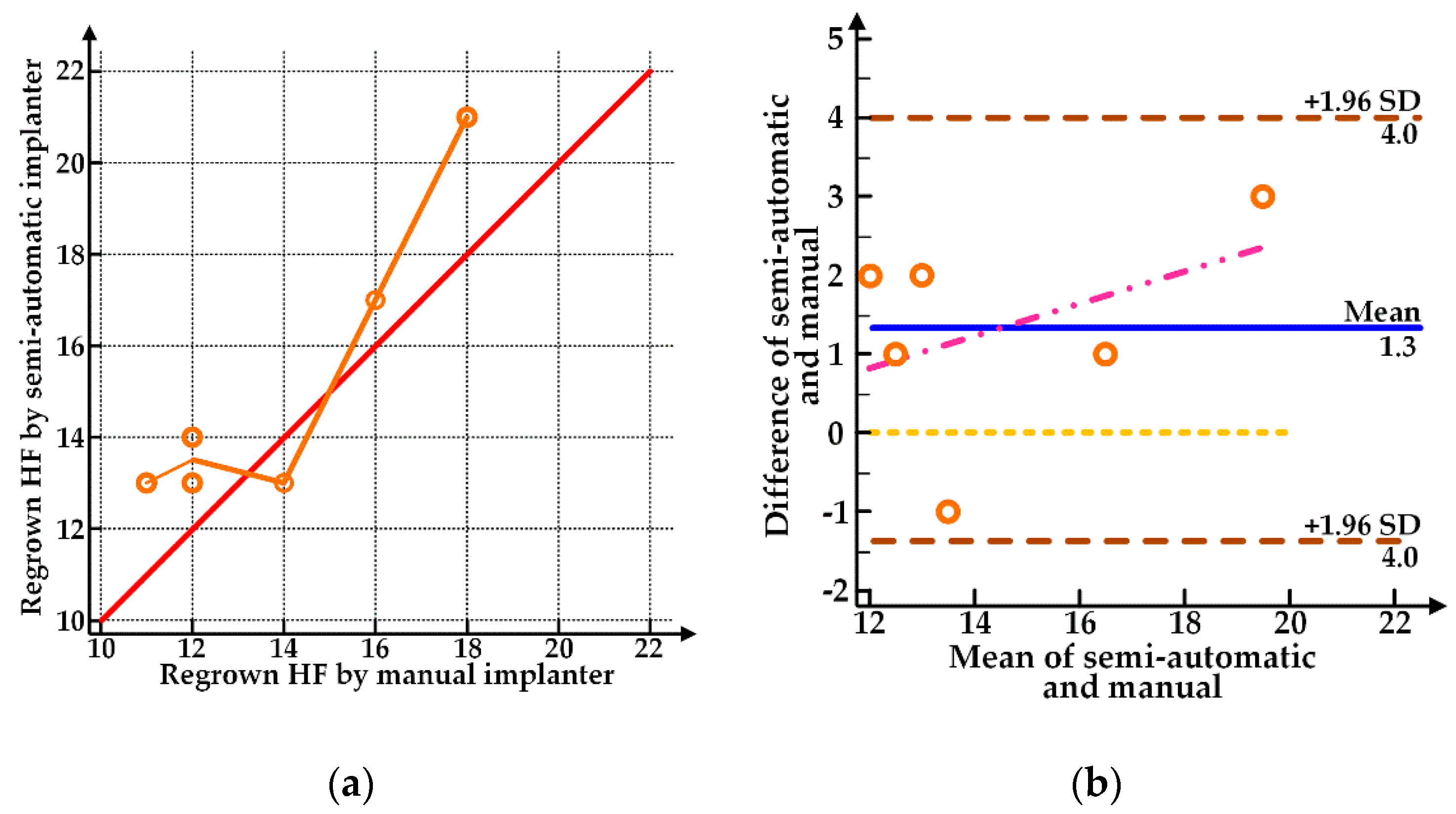
4.2.4. Evaluation of the HF Engraftment Rate

The number of HFs grown at the transplanted site using the semi-automatic implanter and manual implanter was measured 12 weeks after surgery, and the results are shown in Table 3. The measured values for the HF engraftment rates of the manual implanter and the semi-automatic implanter were analyzed by paired t-test [38]. Originally, there were 8 clinical subjects, but according to the clinical trial plan, a total of 6 patients completed the clinical trial, except for 1 dropout due to hair transplant failure (device malfunction during surgery) and 1 dropout due to IRB recommendation. The null hypothesis (H0) is that the clinical effectiveness of the semi-automatic implanter will be different from that of the manual implanter. The alternative hypothesis (H1) is that the clinical effectiveness of the semi-automatic implanter will not differ from that of the manual implanter. The difference between the HFs regrown by the manual implanter and the semi-automatic implanter satisfied the normality in both Kolmogorov–Smirnov and Shapiro–Wilk as the significance probability was higher than the significance level (p = 0.06) as shown in Table 4. The result of the statistical analysis shows that the average number of regrown HFs by the semi-automatic implanter was 1.33 (6% higher engraftment rate), more than that of the manual implanter (p = 0.062). Both the semi-automatic implanter and manual implanter showed above-average engraftment rates, and it could be confirmed that the semi-automatic implanter was not inferior to the manual implanter. According to the clinical experiment results, the semi-automatic implanter met the criteria of follicle engraftment rate, which is the primary criterion of efficacy.
Through Pearson’s correlation analysis [39], the correlation between the engraftment rates of the two devices was identified. This study assumed that the mechanically operated semi-automatic implanter and the manual implanter operated by human experience are independent. The Pearson’s correlation coefficient was 0.911 (95% confidence interval: 0.379–0.990), and it also showed a tendency for a high engraftment rate by the semi-automatic implanter for the subjects with high engraftment rate by the manual implanter, as shown in Figure 15a. The intra-class correlation coefficient (ICC) was 0.896 (95% confidence interval: 0.436–0.985), which was lower than the Pearson’s correlation coefficient. However, this is due to an average 6% higher engraftment rate in the semi-automatic implanter. Further, ICC shows that the HF engraftment rate by the semi-automatic implanter is high in the subjects with high HF engraftment rate by the manual implanter. As shown in the Bland–Altman plot in Figure 15b, the HF engraftment rates of the two devices can be considered to be consistent because the lines of agreement between the two devices did not exceed the 95% limit. In addition, the sum all the values of the semi-automatic implanter minus that of manual implanter (vertical axis) is higher than zero. This indicates that the HF engraftment rate of the semi-automatic implanter is superior to that of the manual implanter. Overall, the correlation between the two devices was very high, indicating a minimal difference in the engraftment rate between the two devices in the same subject.
To date, the HF engraftment rate by manual implant surgery is considered very high [21]. In our experiments, the semi-automatic implanter showed 6% higher HF engraftment rates than the manual implanter. Figure 15 may not be statistically meaningful, but it is important in that it confirms the possibility that delicate procedures of existing manual implanters can be automated. The actual engraftment rate in clinical experiments is lower than that in mice experiments because rats lack immunity, whereas the human scalp is significantly affected by individual immunity as well as the condition of HFs and scalp.

4.2.5. Evaluation of VSA and Adverse Events

Folliculitis, inflammatory pigmentation, and adverse reactions did not occur in all six subjects who completed the clinical experiment with VSA.

4.3. Detection Results of Hair Root

Figure 16 shows the detection results of hair roots for two close-up hair images according to the hair root detection procedure mentioned in Section 3.8. The detected hair roots are indicated by small red squares in the detected image. The acquired input images are close-up images of the shaved posterior scalp before strip harvesting. In the erosion image, noises and particles in the binary image were removed, and in the dilation image, the discrimination between the skin region and the hair region was improved. The number of labels (or hair regions) for IMG1 and IMG are 26 and 22, respectively. In the IMG1, the slender hair was removed during the erosion process and was not detected (yellow triangle). In the IMG2, in case two hairs were attached, they were misdetected with one root (red dot). Nevertheless, overall, the hair roots are well detected for the given input images.

5. Discussion

Owing to thousands of repetitive movements per patient, surgeons feel much fatigue in surgery, which can affect the overall surgical outcome. In continuous HF transplantation by the semi-automatic implanter, as the number of implant needles inserted into the increases, the surgical fatigue caused by the existing manual implanter decreases. Therefore, surgery can be more efficiently performed by increasing the number of needles inserted into the NSM within the spring tension.
In the clinical experiment, both devices showed above-average HF engraftment rates for the six subjects. In addition, the difference in the HF engraftment rate between the two devices was very small for the same subject. The performance of the semi-automatic implanter is equivalent to that of the manual implanter, and the transplanting mechanism of the manual implanter is well reflected in the semi-automatic implanter. While the engraftment rate of the existing manual implanter is affected by the surgeon skill, the semi-automatic implanter can always obtain an excellent engraftment rate regardless of the surgeon’s experience. In addition, future improvements of the implanting speed of the semi-automatic implanter can further reduce the surgery time. An automated implanter that automates the manual implanter can speed up the popularity of hair transplants by reducing hair transplant costs.
The core technology of the semi-automatic implanter lies in the mechanism of planting the HFs by continuously transferring the needle, loaded with the HFs, in the magazine, and by defining the movement of the needle and the rod of the manual implanter. In the structure of the manual planter, the rod that supports the HF at transplant is always in the long needle fixed to the body. The key idea for the automation of the manual implanter with such a structure and for miniaturization of the HF supply device started by detaching the rod from the needle. This led to the design of the NSM, a miniature follicle supply device, and the gripper for gripping the needle and inserting the rod into the needle. The design of these key components renders a disposable needle the basic unit of HF storage, which can reduce the cost of replacing the surgical equipment, that is, the manual implanter. The biggest achievement of this study is the automation of the HF transplantation mechanism in the manual implanter. By changing the setting values of each motor for each transplant stroke shown in Table 1, a surgeon can find the optimal setting values that maximize the engraftment rate while minimizing the damage to HFs during the transplantation process.

6. Conclusions

The current hair transplantation procedure is divided into two stages: Follicle extraction and follicle transplantation. The follicle extraction technique is automated using a motor and image processing techniques, such as P-FUE and ARTAS. Meanwhile, the follicle transplant technique mostly uses simple tools, such as FUE tweezers and FUT’s manual implanter, with relatively less automation. Follicle extraction is easy to automate because it is completed by a simple punching operation, whereas follicle transplantation is not easy to automate because of various considerations, such as implant depth, speed, and direction. Therefore, this study proposes a semi-automatic implanter structure to improve the method of completely manual follicular transplantation. The semi-automatic implanter was developed based on the long experience and know-how of hair transplantation surgeons. The developed semi-automatic implanter system allows even novice surgeons to obtain a high engraftment rate, which is equivalent to that of highly skilled surgeons. It may also reduce the cost of surgery as the hair transplantation procedure is simplified. Furthermore, it can be connected to a surgical robot and utilized in a fully automatic hair transplantation system.

Author Contributions

Conceptualization, T.W.B.; methodology, T.W.B. and Y.C.J.; software, T.W.B.; validation, T.W.B. and Y.C.J.; formal analysis, T.W.B. and Y.C.J.; investigation, T.W.B. and Y.C.J.; resources, T.W.B. and Y.C.J.; data curation, T.W.B. and Y.C.J.; writing—original draft preparation, T.W.B.; writing—review and editing, T.W.B.; visualization, T.W.B.; supervision, K.H.K.; project administration, K.H.K.; funding acquisition, K.H.K. All authors have read and agreed to the published version of the manuscript.

Funding

This work was supported by Electronics and Telecommunications Research Institute (ETRI) grant funded by the Korean government. [20ZD1140, Development of ICT Convergence Technology for Daegu-Gyeongbuk Regional Industry].

Acknowledgments

We are thankful to Prof. Moon Kyu Kim at Kyungpook National University School of Medicine, Chang Heok Hong at Korean DNC, Jae Yel Suh, Yeong Kuk Sohn, and Byeong Wook Ahn at Sung San Precision Co., Ltd., Seong Yeol Park Dentis Co., Ltd., Prof. Byung Cheol Park at Dankook University Hospital, and Sang Hyun Joung, Hyun Hee Bang at MDRIP.

Conflicts of Interest

The authors declare no conflict of interest.

References

  1. Okuda, S. The study of clinical experiments of hair transplantation. Jpn. J. Dermatol. Urol. 1939, 46, 135–138. [Google Scholar]
  2. Unger, W.P. Delineating the safe donor area for hair transplanting. Am. J. Cosmet. Surg. 1994, 11, 239–243. [Google Scholar] [CrossRef]
  3. Unger, W.P.; Shapiro, R.; Unger, R.; Unger, M. Hair Transplantation, 5th ed.; CRC Press: Florida, FL, USA, 2011; pp. 247–251. [Google Scholar]
  4. Lee, I.J.; Jung, J.H.; Lee, Y.R.; Kim, J.C.; Hwang, S.T. Guidelines on hair restoration for east asian patients. Dermatol. Surg. 2016, 42, 883–892. [Google Scholar] [CrossRef]
  5. ISHRS 2015 Data: Hair Transplants Up 76% from 2006. Available online: https://www.plasticsurgerypractice.com/client-objectives/rejuvenation/hair-transplant/ishrs-2015-data-hair-transplants-76-2006 (accessed on 23 October 2019).
  6. Orentreich, N. Autografts in alopecias and other selected dermatological conditions. Ann. N. Y. Acad. Sci. 1959, 83, 463–479. [Google Scholar] [CrossRef] [PubMed]
  7. Robert, M.; Bernstein, M.D.; William, R.; Rassman, M.D. Follicular unit transplantation. Dermatol. Clin. 2005, 23, 393–414. [Google Scholar]
  8. Lam, S.M.; Williams, K.L. Hair Transplant 360: Follicular Unit Extraction (FUE), 1st ed.; Jaypee Brothers Medical Pub: London, UK, 2016; pp. 453–464. [Google Scholar]
  9. Rassman, W.R.; Bernstein, R.M.; McClellan, R.; Jones, R.; Worton, E.; Uyttendaele, H. Follicular unit extraction: Minimally invasive surgery for hair transplantation. Dermatol. Surg. 2002, 28, 720–727. [Google Scholar] [CrossRef] [PubMed]
  10. Dua, A.; Dua, K. Follicular unit extraction hair transplant. J. Cutan. Aesthet. Surg. 2010, 3, 76–81. [Google Scholar] [PubMed]
  11. Rassman, W.R.; Carson, S. Micrografting in extensive quantities: The ideal hair restoration procedure. Dermatol. Surg. 1995, 21, 306–311. [Google Scholar] [CrossRef] [PubMed]
  12. Rashid, R.M.; Morgan, B.L.T. Follicular unit extraction hair transplant automation: Options in overcoming challenges of the latest technology in hair restoration with the goal of avoiding the line scar. Dermatol. Online J. 2012, 18, 12. [Google Scholar] [PubMed]
  13. Onda, M.; Igawa, H.H.; Inoue, K.; Tanino, R. Novel technique of follicular unit extraction hair transplantation with a powered punching device. Dermatol. Surg. 2008, 34, 1683–1688. [Google Scholar]
  14. FUE Hair Transplant Procedure. Available online: http://www.bosley.com/solutions/follicular_unit_extraction.php (accessed on 23 October 2019).
  15. Qureshi, S.A.; Bodduluri, M. System and Method for Classifying Follicular Units. U.S. Patent US7477782B2, 13 January 2009. Available online: http://www.google.tl/patents/US7477782 (accessed on 23 October 2019).
  16. Qureshi, S.A.; Bodduluri, M. System and Method for Classifying Follicular Units. U.S. Patent US7627157B2, 1 December 2009. Available online: https://www.google.com/patents/US7627157 (accessed on 23 October 2019).
  17. Bodduluri, M.; Gildenberg, P.L.; Caddes, D.E. System and Methods for Aligning a Tool with a Desired Location or Object. U.S. Patent US7962192B2, 14 June 2011. Available online: https://www.google.com/patents/US7962192 (accessed on 23 October 2019).
  18. ARTAS Robotic Hair Restoration. Available online: http://restorationrobotics.com (accessed on 23 October 2019).
  19. Shin, J.W.; Kwon, S.H.; Kim, S.A.; Kim, J.Y.; Na, J.I.; Park, K.C.; Huh, C.H. Characteristics of robotically harvested hair follicles in Koreans. J. Am. Acad. Dermatol. 2015, 72, 146–150. [Google Scholar] [CrossRef] [PubMed] [Green Version]
  20. Kim, J.C. Hair Transplanter. U.S. Patent US6461369B1, 8 October 2002. Available online: https://www.google.ch/patents/US6461369 (accessed on 23 October 2019).
  21. Lee, S.J.; Lee, H.J.; Hwang, S.J.; Kim, D.W.; Jun, J.B.; Chung, S.L.; Kim, J.C. Evaluation of survival rate after follicular unit transplantation using the KNU implanter. Dermatol. Surg. 2001, 27, 716–720. [Google Scholar] [PubMed]
  22. Lee, D.Y.; Lee, J.H.; Yang, J.M.; Lee, E.S. New instrument for hair transplant: Multichannel hair transplanter. Dermatol. Surg. 2005, 31, 379. [Google Scholar] [CrossRef] [PubMed]
  23. Pathomvanich, D.; Imagawa, K. Hair Restoration Surgery in Asians; Springer: Berlin, Germany, 2010; pp. 169–171. [Google Scholar]
  24. KNU Implanter. Available online: http://www.hairmedical.co.kr/eng/c03/c03_03.html (accessed on 23 October 2019).
  25. Bae, T.W.; Jung, Y.C.; Kim, K.H.; Kim, M.K.; Kim, J.C.; Suh, J.W.; Lee, H.S.; Choi, E.C.; Kim, D.S.; Hong, C.H. Manual Follicle-Transplanting Hair Transplanter for Increasing Graft Survival Rate. U.S. Patent US10251674B2, 9 April 2019. Available online: https://patents.justia.com/patent/10251674 (accessed on 11 June 2020).
  26. Bae, T.W.; Kim, K.H.; Kim, M.K.; Kim, J.C.; Suh, J.W.; Lee, S.I.; Lee, H.S.; Jung, Y.C.; Choi, E.C.; Kim, D.S.; et al. Automatic Hair Transplanter for Transplanting Follicles. U.S. Patent US 20170020565A1, 1 January 2017. Available online: https://www.freshpatents.com/-dt20170126ptan20170020565.php (accessed on 23 October 2019).
  27. EPOS2 Digital Positioning Controller. Available online: https://www.maxongroup.com/maxon/view/product/control/Positionierung/367676 (accessed on 23 October 2019).
  28. Korea Compliance Testing Laboratories. Available online: www.kctl.co.kr (accessed on 23 October 2019).
  29. Korea Testing Certification. Available online: https://www.ktc.re.kr (accessed on 23 October 2019).
  30. Korea Testing Laboratory. Available online: https://www.ktl.re.kr (accessed on 23 October 2019).
  31. Korea Conformity Laboratories. Available online: https://www.kcl.re.kr (accessed on 23 October 2019).
  32. Medical Device Information & Technology Assistance Center. Available online: https://www.greenpiatech.com (accessed on 23 October 2019).
  33. Korea Testing & Research Institute. Available online: www.ktr.or.kr (accessed on 23 October 2019).
  34. Medical Device Information & Technology Assistance Center. Available online: http://www.nids.or.kr (accessed on 23 October 2019).
  35. Daegu Regional Korea Food & Drug Administration. Available online: https://www.mfds.go.kr/wpge/m_154/de010728l001.do (accessed on 23 October 2019).
  36. Oh, J.W.; Kloepper, J.; Langan, E.A.; Kim, Y.; Yeo, J.; Kim, M.J.; His, T.C.; Rose, C.; Yoon, G.S.; Lee, S.J.; et al. A guide to studying human hair follicle cycling in vivo. J. Investig. Dermatol. 2016, 136, 34–44. [Google Scholar] [CrossRef] [PubMed] [Green Version]
  37. ISO 11137 Gamma & E-Beam Sterilization for Medical Devices. Available online: https://lso-inc.com/sterilization-validation-services/iso11137-gamma-ebeam-sterilization.html (accessed on 23 October 2019).
  38. Paired t-Tests. Available online: http://www.statstutor.ac.uk/resources/uploaded/paired-t-test.pdf (accessed on 23 October 2019).
  39. Data Analysis. Available online: http://learntech.uwe.ac.uk/da/Default.aspx?pageid=1442 (accessed on 23 October 2019).
Figure 1. Hair follicle (HF) extraction: (a) Strip harvesting, (b) follicular unit extraction (FUE), and (c) ARTAS. Transplantation methods: (d) Manual implanter (KNU implanter).
Applsci 10 04046 g001
Figure 2. Problems of manual implanter.
Applsci 10 04046 g002
Figure 3. Survey on development of automated hair implanter; (a) hair transplantation method, (b) surgery time, and (c) willingness to use automated equipment.
Applsci 10 04046 g003
Figure 4. Behavior analysis of hair transplant procedure using manual implanter.
Applsci 10 04046 g004
Figure 5. (a) Operation sequence and (b) configuration of the manual implanter.
Applsci 10 04046 g005
Figure 6. Structure of the proposed semi-automatic implanter.
Applsci 10 04046 g006
Figure 7. Operation flowchart for continuous needle supply and follicle transplantation. NSM: needle supply magazine.
Applsci 10 04046 g007
Figure 8. Grip and release of needle by the gripper. (a) Structure of the gripper, (b) needle grip of the gripper, and (c) gripper part.
Applsci 10 04046 g008
Figure 9. Operation sequence of the needle and the rod. (a) Initial step, (b) shaft advance step, (c) needle grip step, (d) rod moving step, (e) insertion step, (f) implant step, (g) needle separation step, and (h) initial step.
Applsci 10 04046 g009
Figure 10. Guide structure for needle transfer.
Applsci 10 04046 g010
Figure 11. Driving environment for semi-automatic implanter. (a) Driving environment, (b) state of needle and rod at transplant, and (c) transplantation ability test.
Applsci 10 04046 g011
Figure 12. Proposed motor control program using the EPOS2 digital positioning controller.
Applsci 10 04046 g012
Figure 13. Animal experiment result. (a) nude mouse, (b) regrown HFs, and (c) regrown hair.
Applsci 10 04046 g013
Figure 14. Procedure of the clinical experiment using the semi-automatic implanter. (a) Deploying the semi-automatic implanter, (b) loading a HF in a needle, (c) inserting an HF-loaded needle into the NSM, (d) mounting the NSM on the semi-automatic implanter, (e) gripping the semi-automatic implanter, (f) transplantation, and (g) control software GUI.
Applsci 10 04046 g014
Figure 15. (a) Consistency and (b) comparison of engraftment rate.
Applsci 10 04046 g015
Figure 16. Hair root detection results for two close-up hair images.
Applsci 10 04046 g016
Table 1. Setting value of each motor per transplant stroke.
No.Needle Motor (N-Motor)Rod Motor (R-Motor)
DirectionNo. of RotationsSpeed (rpm)Acceleration (rad/s2)Deceleration (rad/s2)DirectionNo. of RotationsSpeed (rpm)Acceleration (rad/s2)Deceleration (rad/s2)
1Forward9728135020,00020,000
2Forward3584135020,00020,000Forward3584135020,00020,000
3 Forward12,083135020,00020,000
4Forward24,422135020,00020,000Forward25,221135020,00020,000
5Reverse6656135020,00020,000
6Reverse17,766135020,00020,000Reverse28,088135020,00020,000
7 Reverse12,800135020,00020,000
8Reverse13,312135020,00020,000
Table 2. Comparison of engraftment rate test for semi-automatic implanter and manual implanter.
Proposed Semi-Automatic ImplanterManual Implanter
Mouse NumberTransplantedRegrownTransplantedRegrown
No. 1.5486
No. 2.1313105
No. 3.9988
No. 4.77106
Sum34333625
Engraftment rate97% (33/34)70% (25/36)
Table 3. Comparison of HF engraftment rate by the two devices.
No.Manual ImplanterSemi-Automatic Implanter
11214
21113
31821
41413
51617
61213
Average number of regrown HFs (Mean ± SD)13.8 ± 2.715.2 ± 3.3
Engraftment rate55% (83/150)61% (91/150)
Table 4. Normality test of difference (Manual—Semi-automatic).
DifferenceKolmogorov–Smirnov
Statistics
0.237
Degree of Freedom
6
Significance Probability
0.200
Shapiro–Wilk
Statistics
0.927
Degree of Freedom
6
Significance Probability
0.554

