Review

Optical Angle Sensor Technology Based on the Optical Frequency Comb Laser

Department of Finemechanics, Tohoku University, 6-6-01, Aramaki Aza Aoba, Aoba-ku, Sendai, Miyagi 980-8579, Japan
*
Author to whom correspondence should be addressed.
Appl. Sci. 2020, 10(11), 4047; https://doi.org/10.3390/app10114047
Submission received: 29 May 2020 / Revised: 5 June 2020 / Accepted: 8 June 2020 / Published: 11 June 2020
(This article belongs to the Special Issue Manufacturing Metrology)

Abstract

:
A mode-locked femtosecond laser, which is often referred to as the optical frequency comb, has increasing applications in various industrial fields, including production engineering, in the last two decades. Many efforts have been made so far to apply the mode-locked femtosecond laser to the absolute distance measurement. In recent years, a mode-locked femtosecond laser has increasing application in angle measurement, where the unique characteristics of the mode-locked femtosecond laser such as the stable optical frequencies, equally-spaced modes in frequency domain, and the ultra-short pulse trains with a high peak power are utilized to achieve precision and stable angle measurement. In this review article, some of the optical angle sensor techniques based on the mode-locked femtosecond laser are introduced. First, the angle scale comb, which can be generated by combining the dispersive characteristic of a scale grating and the discretized modes in a mode-locked femtosecond laser, is introduced. Some of the mode-locked femtosecond laser autocollimators, which have been realized by combining the concept of the angle scale comb with the laser autocollimation, are also explained. Angle measurement techniques based on the absolute distance measurements, lateral chromatic aberration, and second harmonic generation (SHG) are also introduced.

1. Introduction

The angle and length are among the most fundamental parameters that determine the form of an object [1,2]. As can be seen in measurements of the angle between two surfaces of parts or assemblies by a protractor or fixed angle gauges, angle measurement has been carried out since ancient times [3]. In the current production engineering, angle sensors play important roles in many types of machine tools, arm robots, and measuring instruments [4]. For measurement of the angular displacement or angular position of an object with a fixed axis of rotation, rotary encoders are often employed. In a rotary encoder, a relative angular displacement between a rotating scale disk coupled coaxially with that of the rotating object and a reading head kept stationary with respect to the axis of rotation can be detected by reading circular graduations on the scale disk in an optical or electromagnetic manner [5,6,7,8]. Rotary encoders are capable of carrying out high-precision angle measurement over an angular range of 360° and can be employed as a feedback sensor for the control of the axial position of an object. In the state-of-the-art rotary encoder, a self-calibration method has been established [9,10]. Furthermore, the improvements in the resolution and measurement speed of absolute rotary encoders contribute to achieving further higher positioning accuracy and fabrication throughput in machine tools and robot systems [11].
On the other hand, precision positioning is one of the key technologies for the precise fabrication of a component with a complex surface form such as an aspheric form or a freeform, as well as the fabrication of a device with three-dimensional micrometric or nanometric structures [11]. One-axis precision positioning can be achieved by employing a linear slide equipped with precision displacement sensors such as laser interferometers or linear encoders [12]. In multi-axis machine tools and measuring instruments, multi-dimensional precision positioning is carried out by employing positioning systems composed of such precision linear slides. For further higher precision positioning, it is necessary to evaluate the angular error motions of such linear slides with a high measurement throughput in a non-contact manner [4,13]. The rotary encoders cannot be employed in such applications, since the distance between a reading head and a scale disk cannot be changed during the measurement. For such a purpose, optical autocollimators are often employed [14,15]. By employing a two-dimensional image sensor such as an area sensor or a multi-cell photodiode as the photodetector, two-axis angular displacement can be measured simultaneously [4,16]. Nowadays, optical autocollimators have expanded applications to the surface form measurement of precision optical components [17,18,19,20,21]. In recent years, most of the commercial autocollimators employed a charge-coupled device (CCD) or a complementary metal-oxide semiconductor (CMOS) as their photodetectors for the achievement of a large angle measurement range as well as a high resolution [22,23,24]. One of the disadvantages of employing a CCD image sensor is its low measurement throughput; this can be overcome by employing a CMOS or a PSD (position-sensitive detector) [24]. The relatively large size of the optical setup is another issue for the conventional optical autocollimator, since its large footprint could prevent the optical autocollimator from being employed in machine tools where the space for such a sensor is limited. For the achievement of high measurement throughput and high resolution in a compact manner, a laser autocollimator based on laser autocollimation [25] has been developed. With the employment of a laser diode and a photodiode as a compact light source and a photodetector, respectively, highly sensitive high-speed angular displacement measurement has been achieved [26,27]. A laser autocollimator can also be applied for surface form measurement of precision components [28]. Furthermore, a three-axis laser autocollimator and six-degree-of-freedom (6-DOF) surface encoder capable of measuring the three-axis angular displacement of a grating reflector with a single measurement laser beam [29,30,31,32,33], as well as a three-axis inclinometer [34] based on the principle of the three-axis laser autocollimator, have been developed.
In the field of dimensional metrology, many types of optical sensors employing a mode-locked femtosecond laser, in which the optical frequency of each mode can be directly linked to a national standard of frequency/time, have been developed in the past two decades since the establishment of the laser source [35,36,37,38,39]. For example, methods for measurement of the absolute distance of an object [40,41,42,43,44,45,46] and the absolute thickness of an optical glass [47,48,49] have been developed with the enhancement of a well-controlled pulse repetition rate of the mode-locked femtosecond laser. The establishment of a fiber-based mode-locked femtosecond laser [50,51,52,53] designed in a compact size and capable of being operated stably even in a limited environmental condition has contributed to the growth of these techniques in dimensional metrology. In recent years, the trend of employing a mode-locked femtosecond laser source can also be seen in angle measurement technologies. A new concept of generating an absolute angle scale with the enhancement of the dispersive characteristic of a diffraction grating has been proposed [54], and a femtosecond laser autocollimator based on the concept as well as laser autocollimation, has been established [55,56]. Furthermore, the method has been extended to the measurement of the absolute position of an object [57]. The above-mentioned femtosecond laser autocollimators are based on the well-controlled, equally spaced frequency comb in the spectrum of the mode-locked femtosecond laser. Angle measurement with a mode-locked femtosecond laser source has also been achieved by the phenomenon of chromatic aberration [58], as well as second harmonic generation (SHG) which is a well-known phenomenon in nonlinear optics [59]. Table 1 summarizes the optical methods for angle measurement employing a mode-locked femtosecond laser source. The new angle measurement techniques with a mode-locked femtosecond laser are expected to achieve the performances that cannot be achieved by conventional optical angle sensors with a single-mode laser source or a white light source.
In this review article, optical angle sensors employing a mode-locked femtosecond laser source are investigated. It should be noted that an optical fiber gyro based on the Sagnac effect [64,65] is another method for angle measurement. Many types of optical fiber gyros such as an interferometric Fiber optic gyroscope (I-FOG) [66], a resonator Fiber optic gyroscope (R-FOG) [67] and Brillouin scattering [68] have been developed so far, and some trials have been performed using optical fiber gyros to employ a mode-locked femtosecond laser [60,61]. The measurement principles of these optical fiber gyros are the same as the conventional ones employing a pulsed laser [69]. In addition, optical fiber gyros are not appropriate for applications in production engineering, such as the evaluation of the angular error motion of a precision linear slide or the measurement of the freeform or the aspheric form of an optical component, due to their drift characteristics associated with their principle based on the detection of angular velocity. The optical fiber gyros with a mode-locked femtosecond laser are thus not included in this review article.

2. Angle Measurement Methods Based on the Discrete Modes of a Mode-Locked Femtosecond Laser in Frequency Domain

2.1. A Method Employing the Dispersive Characteristics of a Diffraction Grating

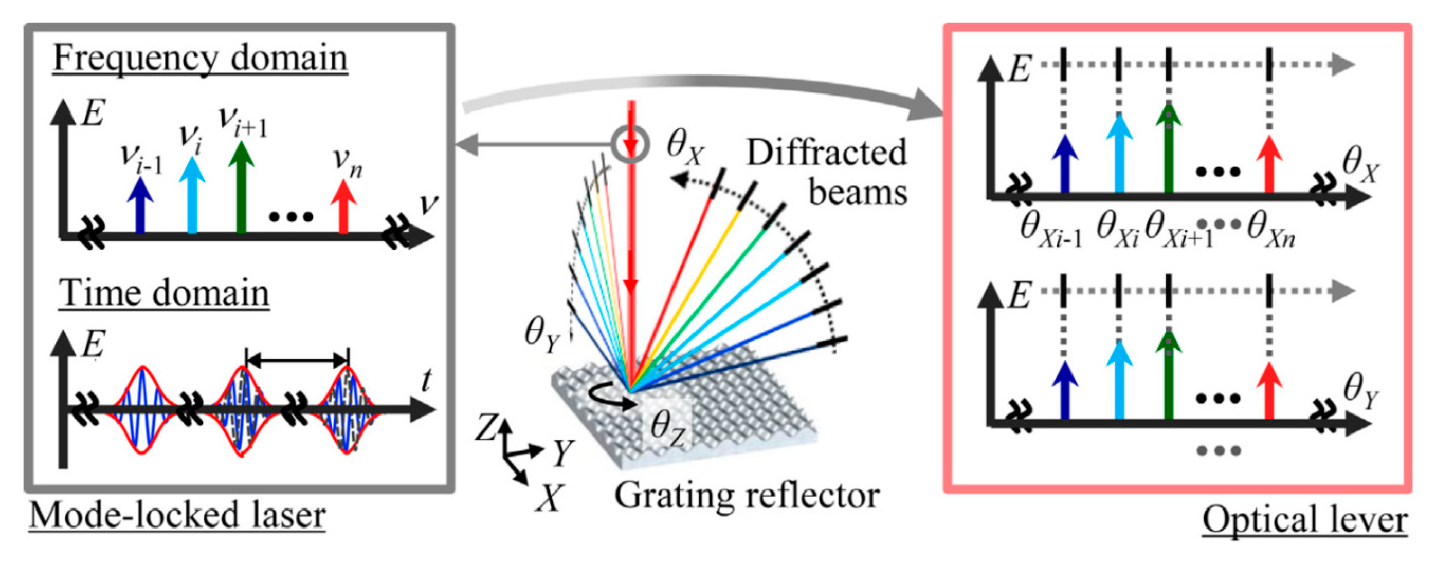
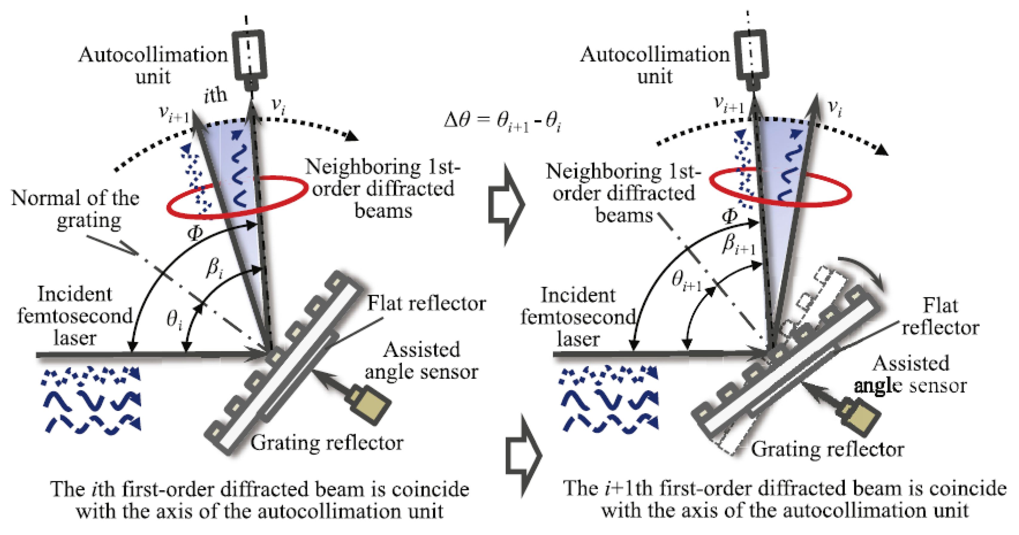
2.1.1. Principle of the Generation of an Angle Scale Comb from an Optical Frequency Comb

The equally-spaced optical modes in a mode-locked femtosecond laser, often referred to as an optical frequency comb, can be employed to generate an “angle scale comb” that can be employed as optical graduations for angle measurement. A schematic of the principle of generating an angle scale comb from a mode-locked femtosecond laser is shown in Figure 1. The angle scale comb is generated with the enhancement of the dispersive characteristics of a diffraction grating. A mode-locked femtosecond laser from a light source is constructed incident to a reflective-type diffraction grating. The ultra-short pulse train of a mode-locked femtosecond laser in the time domain is a series of equally-spaced optical modes with a pulse repetition rate νrep in the frequency domain. A reflective-type diffraction grating generates a series of first-order diffracted beams, in which each optical mode has a different angle of diffraction from those of the others. In the case where a two-dimensional reflective-type diffraction grating is employed as shown in the figure, groups of first-order diffracted beams will be generated in the two directions. It should be noted that only the groups of the positive first-order diffracted beams in the X- and Y-directions are indicated in the figure for the sake of simplicity. The angle of diffraction of the ith optical mode θi in the group of the positive first-order diffracted beams can be expressed as follows [54]:
θ i = arcsin ( c n air g ν i )   ( i = 1 ,   2 ,   3 , ,   n ) ,
where c, nair, g, and νi are the speed of light in vacuum, the refractive index in air, the pitch of the diffraction grating, and the optical frequency of the ith mode, respectively. As can be seen in the Equation, the discrete optical frequency νi in the spectrum of the mode-locked femtosecond laser and the angle of diffraction θi of the ith mode are in a one-to-one relationship, and thus the group of the diffracted beams can be treated as optical graduations for angle measurement: angle scale comb.
The angle scale comb generated from a mode-locked femtosecond laser can be employed for angle measurement. Figure 2a shows one of the examples of applying the angle scale comb for measurement of a rotary table on which a grating reflector is mounted. Since the modes in the angle scale comb pass through the detector one after another with the rotation of the grating reflector, the angular displacement of the rotary table can be detected by monitoring the reading output of the detector. Figure 2b shows another example of the application of the angle scale comb; measurement of the free-form surface of an optical component. In this case, due to the local slope Δθ at a certain position on the free-form surface, the angle of incidence of the reflected beam from the optical component experiences a change in its propagation direction of 2Δθ. The angle scale comb emanating from the grating reflector also experiences a change in its angle of diffraction of 2Δθ. A local slope mapped over the surface of the optical component can thus be obtained by detecting the change in the angle of diffraction of the angle scale comb during the lateral scanning of the optical component. Through the integral calculation of the obtained local slope map, the surface form of the optical component can be reconstructed.
A mode-locked femtosecond laser has superior characteristics as a high-precision, highly stable laser source that can be directly traceable to the national standard of frequency and time [70]. The angle scale comb takes over these characteristics of a mode-locked femtosecond laser. In an ideal case, an angular distance between neighboring comb modes and the angular range in the angle scale comb correspond to the pulse repetition rate and the spectral bandwidth of the mode-locked femtosecond laser, respectively, from which the angle scale comb is generated. In the general case, the pulse repetition rate and the spectral bandwidth of an optical frequency comb are on the order of 100 MHz and 10 THz, respectively; this means that the dynamic range of the angle scale comb (the ratio of the angular range to the angular distance of neighboring modes) thus becomes large.

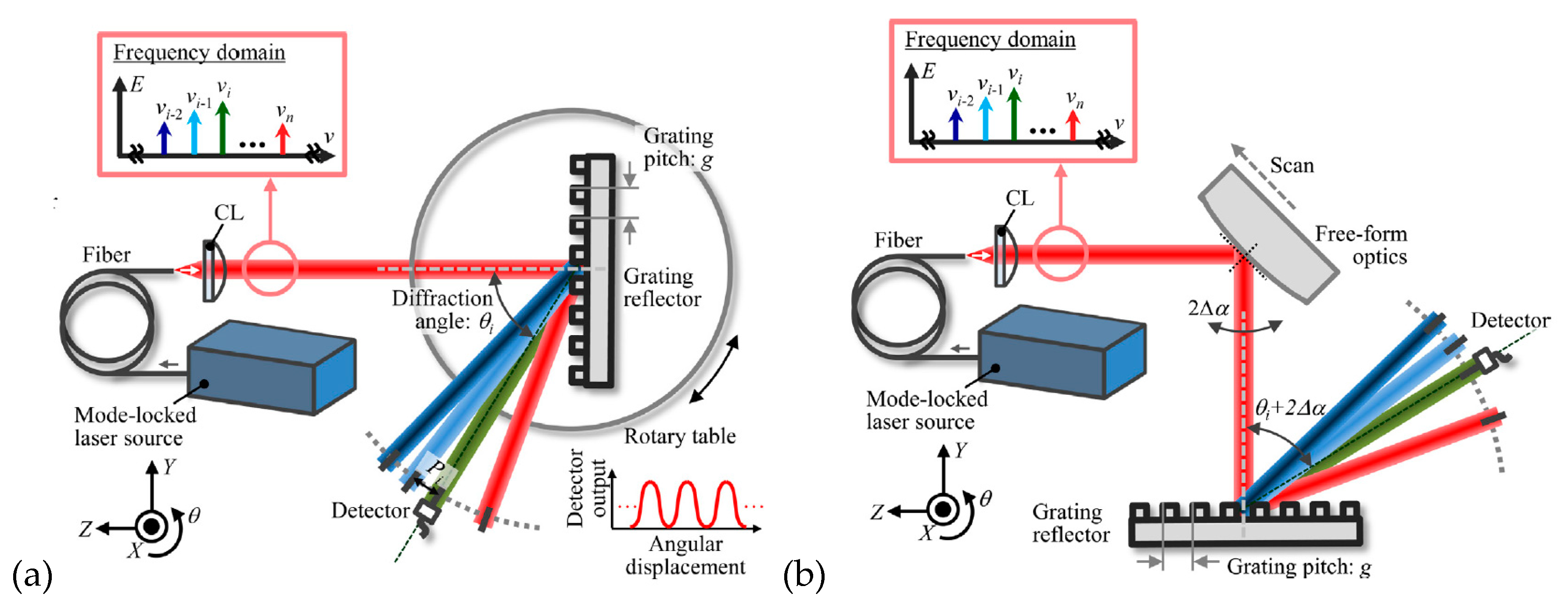
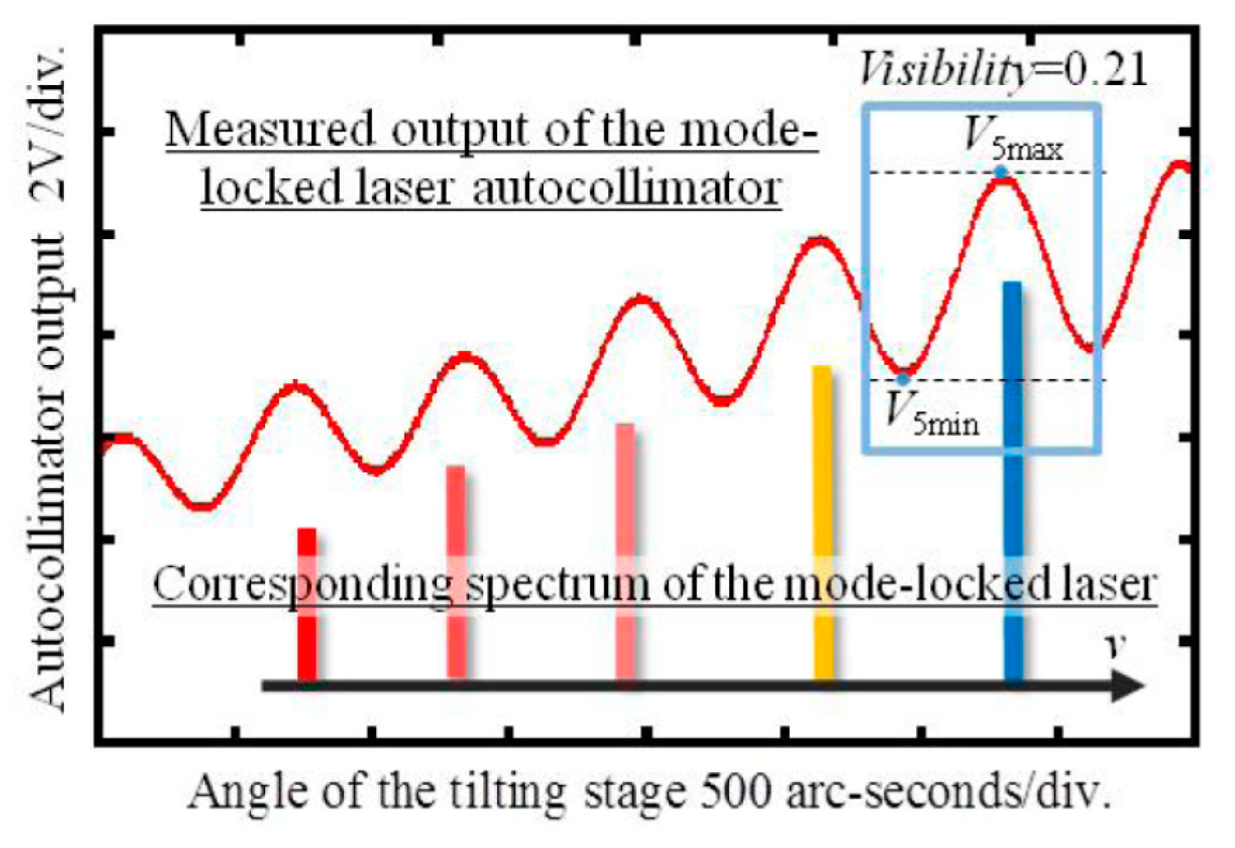
2.1.2. Light Intensity Detecting-Type Mode-Locked Femtosecond Laser Autocollimator

In the optical setups shown in Section 2.1.1., the resolution of the angle measurement can be improved by increasing the distance between the grating reflector and the detector. However, in most of the applications, the space available for the optical setup of the angle scale comb is limited; this fact means that there is a trade-off relationship between the resolution of angle measurement and the size of the optical setup. This issue can be addressed by introducing the laser autocollimation into the optical frequency comb.
Figure 3a shows an example of the optical setup of a conventional laser autocollimator, which is based on the laser autocollimation [25]. A single-mode laser emitted from a laser source such as a laser diode (LD) is collimated by a collimating lens (CL) and is then made incident to a plane mirror reflector through a polarizing beam splitter (PBS) and a quarter-wave plate (QWP). The reflected beam from the plane mirror reflector goes through the QWP again, is reflected by the PBS, and is then captured by an autocollimation unit composed of a collimator objective (CO) and a photodiode (PD). In the autocollimation unit, the active cell of the PD is placed at the back focal plane of the CO so that the laser beam made incident to the CO can be focused on the PD active cell. The displacement Δd of the focused laser beam on the PD active cell due to the angular displacement Δθ of the plane mirror reflector can be expressed by the following Equation [4]:
Δ θ = arctan ( Δ d 2 f )
In the case where a single-cell photodiode is employed as the photodetector to detect the spot displacement Δd as shown in Figure 3a, the measuring range of the photodetector is defined by the diameter D of the focused laser beam on the PD active cell, and the corresponding measuring range of the angular displacement becomes ± arctan(D/4f). The detection sensitivity of Δd by the PD is inversely proportional to the focused spot diameter D [4]. The decrease of D for the achievement of the highly sensitive measurement of the angular displacement is thus required; namely, there is a trade-off relationship between the sensitivity and the measuring range in the conventional laser autocollimator with a photodiode and a single-mode laser source.
A femtosecond laser autocollimator, which can be realized by combining the angle scale comb with the conventional laser autocollimation, can overcome the aforementioned problem. Figure 3b shows a schematic of the femtosecond laser autocollimator in which a mode-locked femtosecond laser source is employed as the light source. In the optical setup of an angle scale comb shown in Figure 2a, the laser autocollimation unit composed of a collimator objective and a single-cell photodiode is newly employed instead of the sole photodetector. As can be seen in Figure 3b, each of the first-order diffracted beams emanating from the grating reflector is focused onto the focal plane of the collimator objective. As a result, a series of focused diffracted beams aligned in a line can be obtained. The relative position of each of the focused beams is determined by Equations (1) and (2). Since all the focused diffracted beams experience the translational displacement on the PD active cell associated with the angular displacement of the grating reflector, a continuous reading output with a cycle corresponding to the relative position of each of the focused diffracted beams can be obtained. Denoting the number of first-order diffracted beams in the angle scale comb as N, a theoretical measurement range of the femtosecond laser autocollimator becomes N times that of the conventional laser autocollimator employing a single-mode laser source and with a single focused spot on the PD active cell. It should be noted that the detection of the displacement of a focused beam in the femtosecond laser autocollimator shown in Figure 3b is based on the photocurrent output from the PD, the amount of which is associated with the intensity of the light rays captured by the active cell on the PD. Therefore, the femtosecond autocollimator with a PD is referred to as the light intensity detecting-type femtosecond laser autocollimator.
Figure 4a,b show a schematic and a photograph of the optical setup for the light intensity detecting-type femtosecond laser autocollimator, respectively. In the setup, a Fabry–Pérot etalon with a free spectral range (FSR) of 770 GHz was employed as an optical bandpass filter to enlarge the distance between the neighboring modes in the spectrum of the optical frequency comb.
Figure 5 shows the obtained photocurrent from the PD converted into the voltage output by a trans-impedance amplifier. As can be seen in the figure, the cycle of the obtained voltage output agreed well with the FSR of the etalon. These results demonstrated that the light intensity detecting-type femtosecond laser autocollimator has a measurement range greater than 11,000 arc-seconds (3.06), which is much larger than that of the conventional laser autocollimator with a single-mode laser source [4,27].

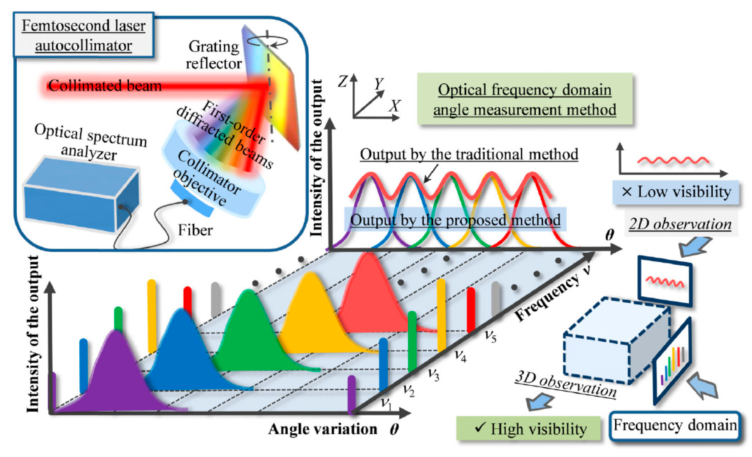
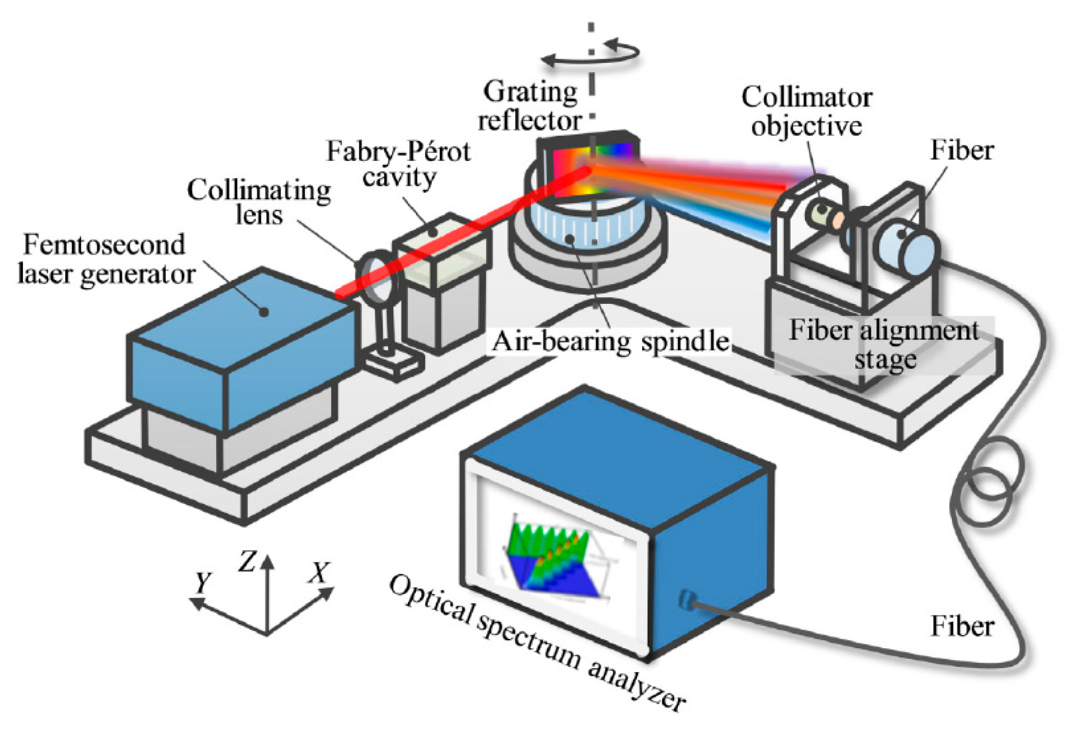
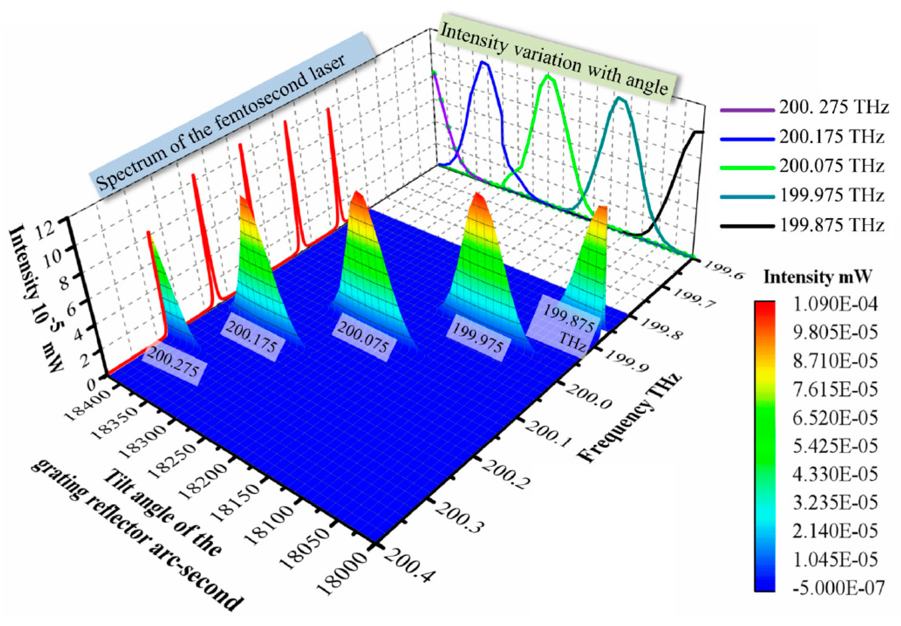
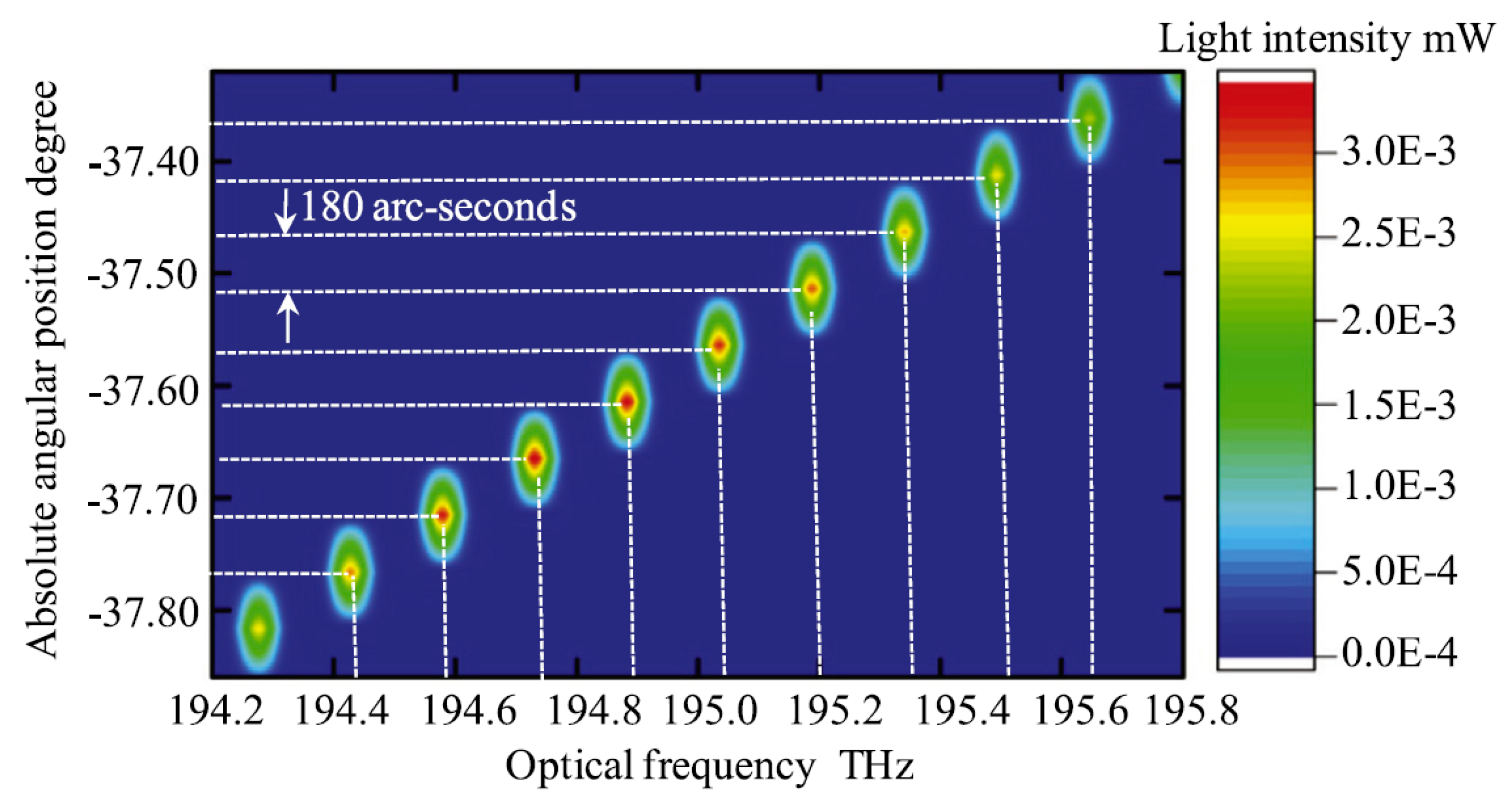
2.1.3. An Optical Frequency Domain Angle Measurement Method Associated with a Mode-Locked Femtosecond Laser Autocollimator

Most of the commercial fiber-based mode-locked femtosecond lasers have a pulse repetition rate on the order of 100 MHz. When such a laser source is employed in the light intensity detecting-type femtosecond laser autocollimator, the distance between the neighboring spots in the focal plane of the collimator objective reaches the order of several nanometers, and the spots cannot be distinguished separately. The pulse repetition rate is thus required to be extended by a Fabry–Pérot etalon in the femtosecond laser autocollimator described in Section 2.1.2. Due to the diffraction limit, it is unavoidable for the neighboring spots in the focal plane of the collimator objective to overlap with each other in most of the cases. This results in the degradation of the signal quality (visibility) of the reading output of the light intensity detecting-type femtosecond laser autocollimator. As can be seen in the result shown in Figure 5, maximum visibility that can be achieved by the femtosecond laser is approximately 0.5; this prevents the light intensity detecting-type femtosecond laser autocollimator to achieve further higher sensitivity.
To address the issue, an optical frequency-domain femtosecond laser autocollimator has been established [56]. Figure 6 shows a schematic of the detection of the angle scale comb in optical frequency domain. A detector unit composed of a collimator objective, a single-mode fiber, and a spectrometer is newly employed. By observing the spectrum of the first-order diffracted beams captured by the single-mode fiber, the angle scale comb can be detected with a visibility of 100%. Furthermore, this technique realizes the direct conversion of the optical frequency comb to the angle scale comb, which contributes to achieving further precision angle measurement.
Figure 7 shows the developed optical frequency-domain femtosecond laser autocollimator. A collimated mode-locked femtosecond laser is made to pass through a Fabry–Pérot etalon with a free spectral range (FSR) of 100 GHz and is then made incident to a grating reflector, and a part of the first-order diffracted beams emanating from the grating surface is captured by the single-mode fiber detector through the collimator objective. The spectrum of the captured laser beam is analyzed by an optical spectrum analyzer. It should be noted that the etalon is employed in this setup to identify each mode in the angle scale comb in optical frequency domain by using a spectrometer with a limited frequency resolution.
Figure 8 shows an example of the angle scale comb observed in optical frequency domain. As can be seen in the figure, each of the comb modes is successfully identified in the optical frequency domain. Although a limited result over an angle range of approximately 400 arc-seconds is indicated in the figure, each of the comb modes is verified to be identified over an angular range of approximately 6°, which is limited by the spectral width of the mode-locked femtosecond laser, as well as the resolving power of the diffraction grating employed in the setup. The expansion of the spectral range of a mode-locked femtosecond laser with a supercontinuum [71] is expected to achieve a further wider measurement range. In addition, the results have demonstrated that a high resolution of 0.03 arc-seconds can be achieved by interpolating the intensity variation of each of the comb modes.
Measurement of the absolute angular position of an object is a difficult task for the conventional autocollimator [17,18,19,20,21,22,23,24] and the laser autocollimator with a single-mode laser source [25,26,27,28], since it is difficult to verify the absolute angular position of a target reflector with respect to the optical axis of the autocollimation unit in a space; namely, the determination of the “zero-angle” position. Although a method employing a retroreflector is available for the zero-angle position adjustment [72], this method can only be applied to the applications where the propagation directions of the incident beam and the reflected beams become parallel to each other. Furthermore, the accuracy of the zero-angle position adjustment is dominated by the accuracy of the retroreflector. This issue can be addressed by the optical frequency-domain femtosecond laser autocollimator with the enhancement of an assisted angle sensor [57]. Figure 9 shows a schematic of the high-precision zero-angle position adjustment in the optical frequency-domain femtosecond laser autocollimator. As can be seen in the figure, Δθ, which is the difference of the angles of diffraction of the (i + 1)th and ith first-order diffracted beams with mode frequencies of νi+1 and νi, respectively, is verified by measuring the angular displacement of the grating reflector by the assisted angle sensor such as a conventional autocollimator or a rotary encoder embedded to the rotary table on which the grating reflector is mounted. By using the obtained Δθ, the absolute angle Φ between the femtosecond laser beam and the optical axis of the laser autocollimation unit can be obtained. It should be noted that the final measurand of the method is not Φ but θ, the angle of the normal of the grating reflector with respect to the incident femtosecond laser.
The above mentioned zero-angle position adjustment can be applied to the optical setup where the propagation directions of the incident beam and the reflected beam are not parallel to each other. Once the angle Φ is confirmed during the fabrication process of the optical head of the mode-locked femtosecond laser autocollimator based on the principle of the optical frequency-domain angle measurement, absolute angle position of the grating reflector with respect to the incident femtosecond laser beam can be obtained with the following measurements.
Figure 10 shows one of the examples of the absolute angle measurement based on the proposed method. As can be seen in the figure, the absolute angular position of the grating reflector in a step of 180 arc-seconds was well distinguished over the absolute angle range from −37.805 degrees to −37.354 degrees in the frequency domain; this means that the optical frequency comb can be directly converted into the angle scale comb for absolute angular position measurement.

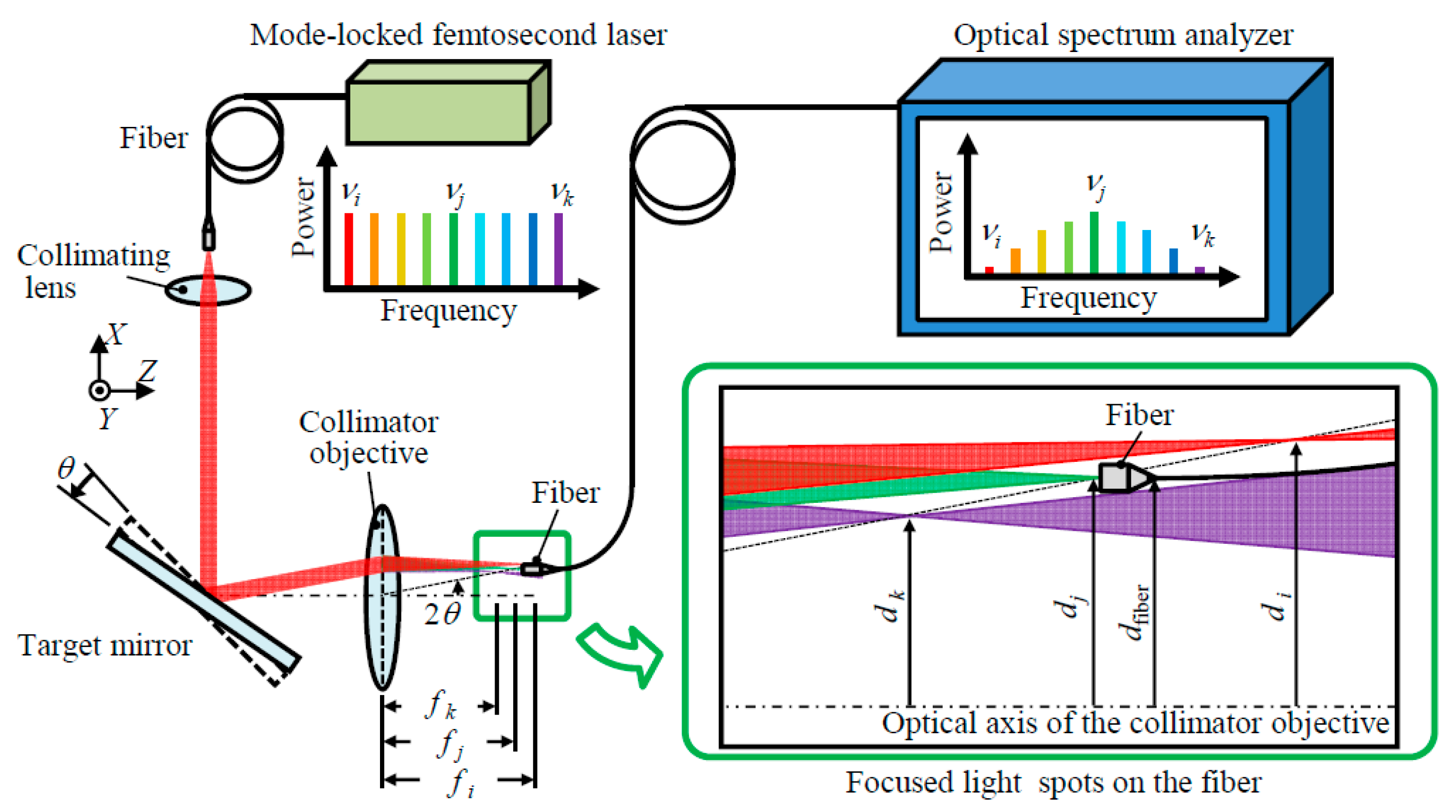
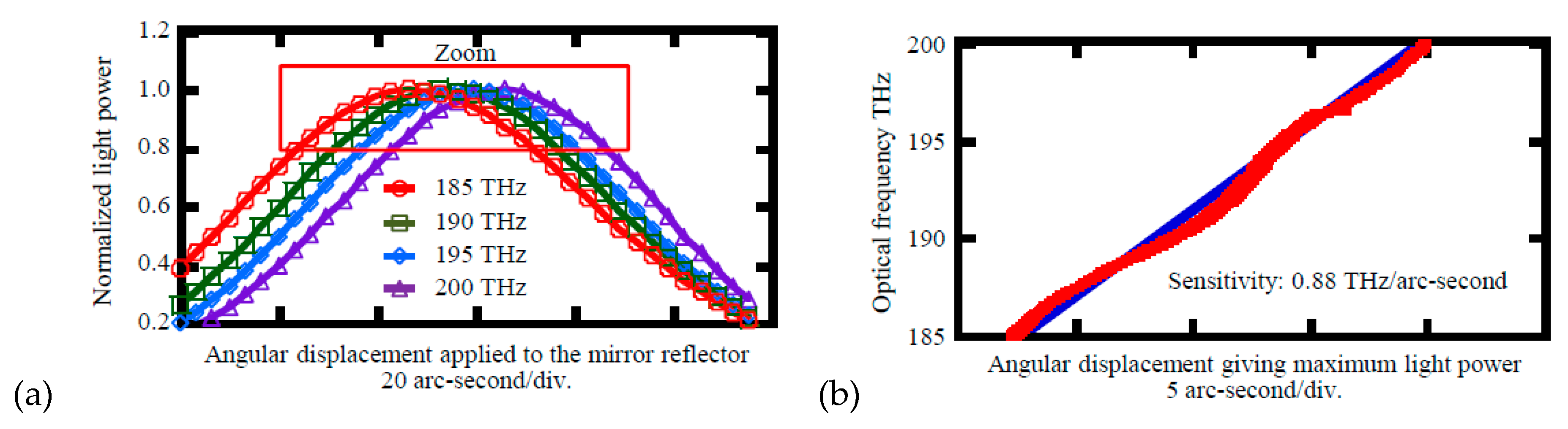
2.2. Methods Based on the Chromatic Aberrations of a Simple Lens

According to the thin-lens equation, the focal length of a simple lens depends on the light wavelength of an incident light via the lens refractive index [73]. When a collimated mode-locked femtosecond laser is made incident to a simple lens in such a way that the laser axis is aligned to be coaxial with respect to the optical axis of the lens, the optical modes in the femtosecond laser are focused at different points on the optical axis of the lens. The light ray from an off-axis point will arrive at a different height above the optical axis; namely, the frequency-dependent lens focal length causes a frequency dependence of the transverse magnification as well [73]. This characteristic, which is referred to as the lateral chromatic aberration, can be employed for measurement of the small angular displacement of an object with the enhancement of the laser autocollimation [25,58].
Figure 11 shows the optical setup for measurement of the small angular displacement of an object based on the chromatic aberrations of a simple lens, where the principle of the laser autocollimation is integrated. A mode-locked femtosecond laser is employed as the light source, while the laser autocollimation unit composed of a collimator objective and a single-mode fiber connected to a spectrometer is employed as the detector for angle measurement. The mode-locked femtosecond laser from the light source is collimated by a collimating lens and is then made incident to a target reflector. The reflected beam is then made incident to the laser autocollimation unit. The fiber detector in the laser autocollimation unit is placed at an off-axis position dFiber (≠0) with respect to the optical axis of the collimator objective; namely, the optical axis of the laser autocollimation unit has an angle with respect to the optical axis of the collimator objective. This arrangement enables the optical setup to detect the small angular displacement of the target reflector with the effect of the lateral chromatic aberration of the lens.
Denoting the focal length of the simple lens for the ith mode in the mode-locked femtosecond laser as fi, the lateral displacement of the focused mode di with respect to the optical axis of the simple lens due to the angular displacement θ of the target reflector can be expressed as follows [58]:
d i = f i tan 2 θ
On the assumption that the mode-locked femtosecond laser has a uniform spectrum over its spectral range, and the optical frequency of the jth mode is the peak frequency in the spectrum of the light rays captured by the fiber detector at the condition where θ = θ0 (≠0), the following relationship should be satisfied [58]:
d fiber = d j = f j tan 2 θ 0
In the same manner, the following Equation should be satisfied in the case with the angular displacement θ0 + Δθ and the corresponding lateral displacement dk of the kth mode at the peak in the spectrum of the captured light rays [58]:
d fiber = d k = f k tan 2 ( θ 0 + Δ θ )
From Equations (4) and (5), the angular displacement of the target reflector Δθ can be obtained as follows [58]:
Δ θ = 1 2 tan 1 ( f j f k tan 2 θ 0 ) θ 0
Since θ0 is known as the design parameter in the optical setup, Δθ can be obtained based on Equation (6) by calculating fj and fk based on the lens equation by using the detected peak frequencies νj and νk of the jth and kth modes, respectively. It should be noted that the setup shown in Figure 11 is similar to that shown in Figure 7 based on the dispersive characteristics of a grating reflector. One of the advantages of the optical setup shown in Figure 11 is that a reflective-type grating reflector is not required for measurement; this contributes to building up the optical setup to a compact size. In addition, an arbitrary reflective surface on an object can be measured by the setup shown in Figure 11. It should also be noted that the angle sensor with the diffraction grating shown in Figure 7 can be employed for the evaluation of an object with a reflective surface without grating pattern structures by modifying the optical setup as shown in Figure 2b. However, in this case, attention should be paid to misalignments of the optical components, as well as the alignment of an object under inspection.
Figure 12a shows the change in the light intensity of each mode captured by the fiber detector analyzed in optical frequency domain. In the figure, only several modes from 185 THz to 200 THz in a frequency difference of 5 THz are plotted for the sake of clarity. As can be seen in the figure, the light intensity of each mode has been changed by the angular displacement of the mirror reflector. Figure 12b shows the peak frequencies observed at each angular position of the mirror reflector. By detecting the peak frequency in the spectrum of the light rays captured by the fiber detector, the angular displacement of the mirror reflector can thus be detected.

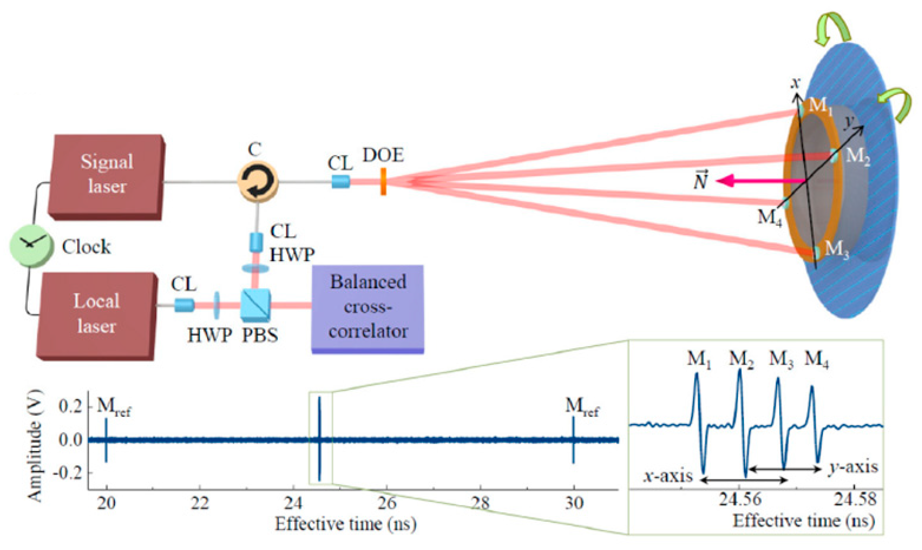
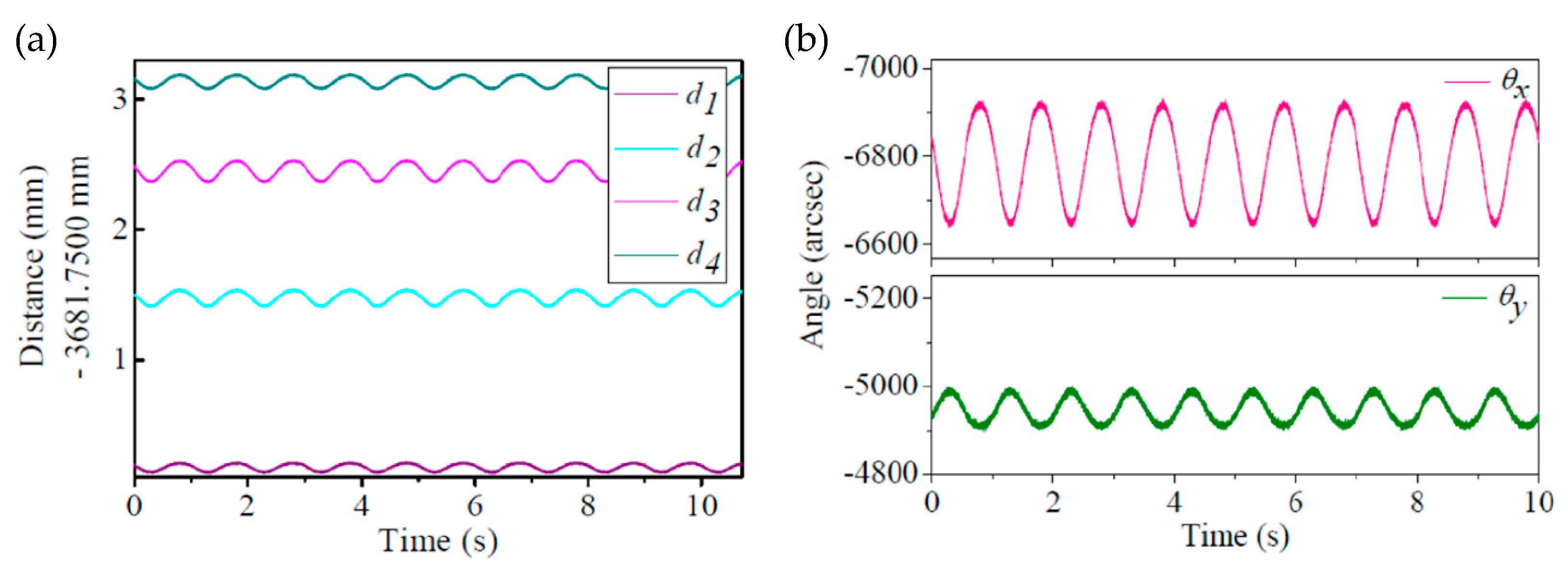
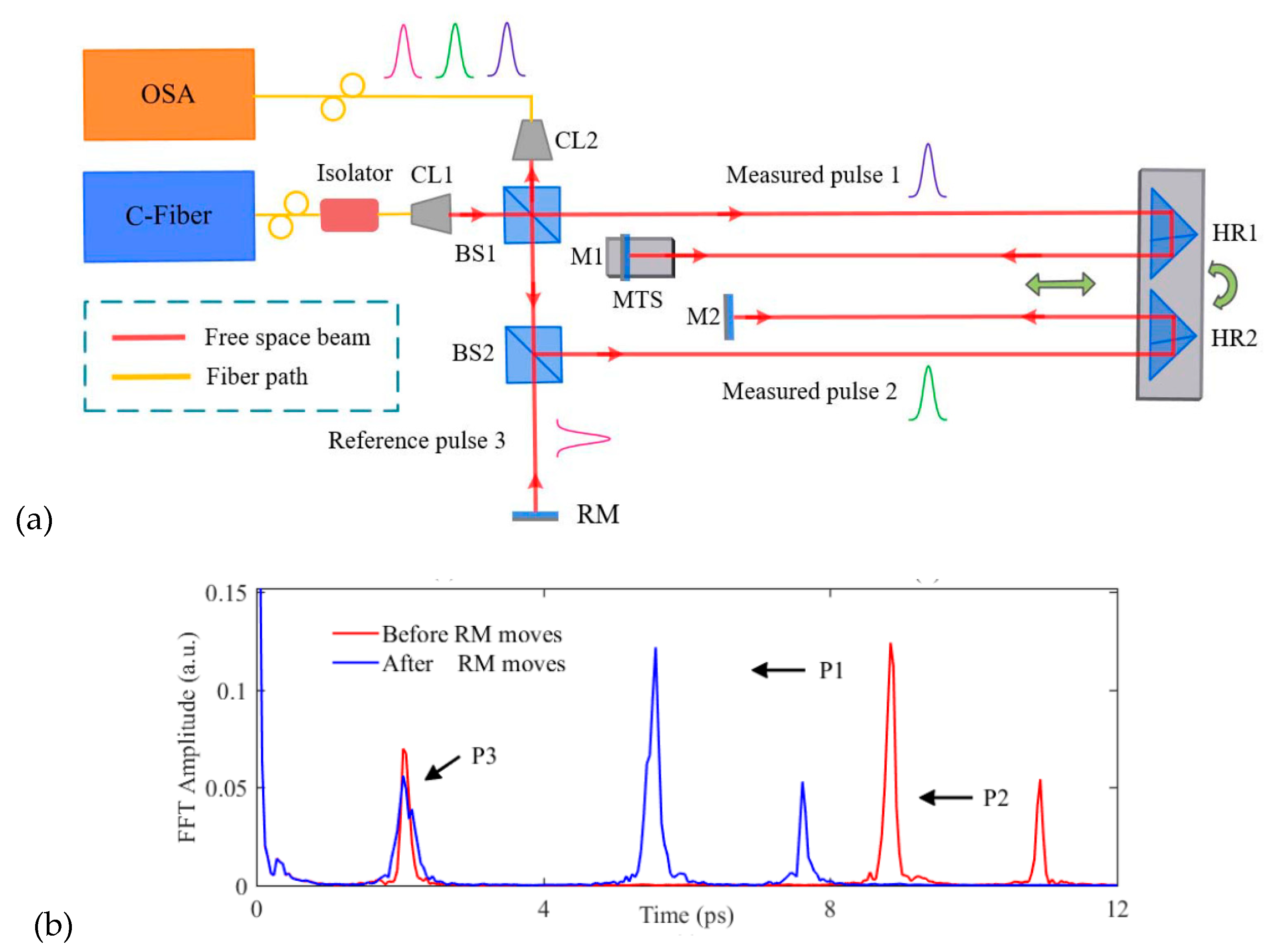
3. Methods Based on the Absolute Distance Measurement

The angular displacement of an object can be measured by multilateration or triangulation [11,74,75] in which the displacements of several points on its surface are measured by interferometric methods [13,76] or non-interferometric methods such as the time-of-flight (TOF) method [77]. By employing a method with a mode-locked femtosecond laser source capable of measuring the absolute distance of a measuring point [40,41,42,43,44,45,46,62,63], absolute angular position measurement can be realized.
Figure 13 shows an example of the absolute angular position measurement based on the absolute distance measurement by the TOF method combined with the second harmonic generation (SHG) [63]. In the proposed method, a pair of the mode-locked femtosecond laser sources synchronized with the same reference clock but with slightly different pulse repetition rates is employed; one of the mode-locked femtosecond lasers is employed as a signal laser, while the other is employed as a local laser for down-conversion. In the setup, the femtosecond laser beam from the light source is at first collimated by a collimating lens (CL) and is then divided into four sub-beams by using a diffractive optical element (DOE). The sub-beams are made incident to the target surface where four mirrors are placed in an angular distance of 90° along the circumference direction to reflect the sub-beams to the DOE. It should be noted that the four mirrors are arranged in such a way that the optical path lengths of the sub-beams become different from each other. The reflected sub-beams are then combined at the DOE and are made to pass through the circulator and to superimpose with the local femtosecond laser in free space. The reflected sub-beams are then converted into electric signals by the balanced cross-correlator based on the principle of the nonlinear optical cross-correlation for measurement of the absolute distance of the four mirrors on the object with respect to the DOE. The novel optical configuration with the DOE and the four mirror reflectors makes it possible to carry out simultaneous measurement of the absolute distances of the four points on the object by a single balanced cross-correlation (BCC) electrical signal in which the four corresponding pulse trains can be observed independently. By using the measured absolute distances di (i = 1, 2, 3, 4) of the mirror reflectors with respect to the DOE, absolute angular positions can be obtained through a simple calculation based on the geometric relationship of the optical components; the X- and Y-directional absolute normal angles of the surface under inspection θx and θy, respectively, with respect to the femtosecond laser beam incident to the DOE can be calculated as θx = sin−1[(d1d3)/A] and θy = sin−1[(d2d4)/A], where A is the distance between the two corresponding mirror reflectors.
Figure 14 shows the detected angular motion of an object placed 3.7 m away from the DOE. In the experiment, angular motion with a frequency of 1 Hz was given to the object by using a piezoelectric tilt stage. Figure 14a shows the absolute displacements measured at the four positions, and Figure 14b shows the angular motions about the X- and Y-axes calculated from the obtained absolute displacements. As can be seen in the figures, the absolute distances at the four positions were successfully detected simultaneously, and the angular motions about the X- and Y-axes were successfully reconstructed from the obtained absolute distances.
Figure 15a shows another example of applying the displacement measurement based on the mode-locked femtosecond laser [62]. The setup is based on a Michaelson interferometer designed to have a single reference arm and two measurement arms by splitting the collimated mode-locked femtosecond laser beam into three beams with beam splitters (BS1 and BS2). Through the demodulation of the interference spectrum of the three beams from the reference arm and the measurement arms based on a Fourier transform method [78], optical path differences among the three beams can be obtained simultaneously, as shown in Figure 15b.
It should be noted that environmental fluctuations (the refractive index of air) could affect the absolute distance measurement [79] in the same manner as the technique based on the single-mode laser source. Angle measurement based on the absolute distance measurement with a mode-locked femtosecond laser source could also be affected by the environmental fluctuations, and attention should be paid to the control of environmental parameters such as temperature, pressure, and humidity.

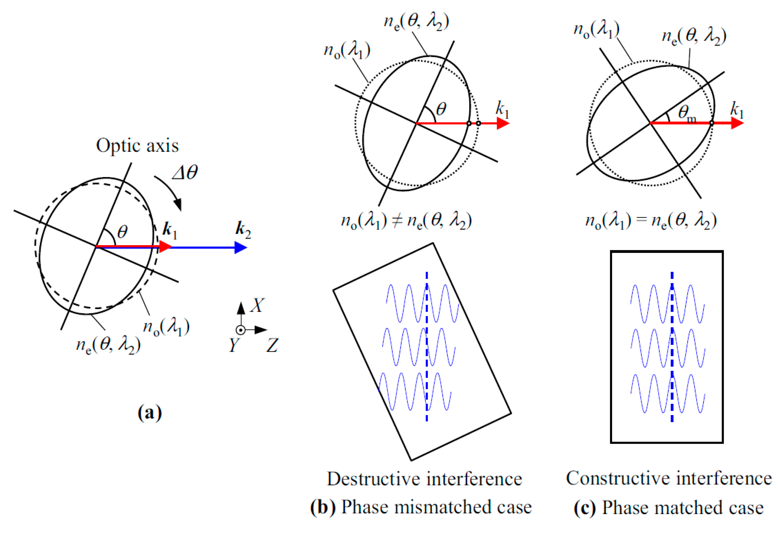
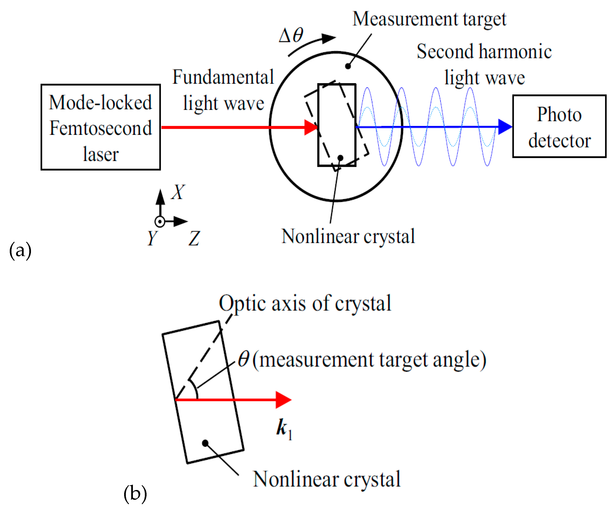
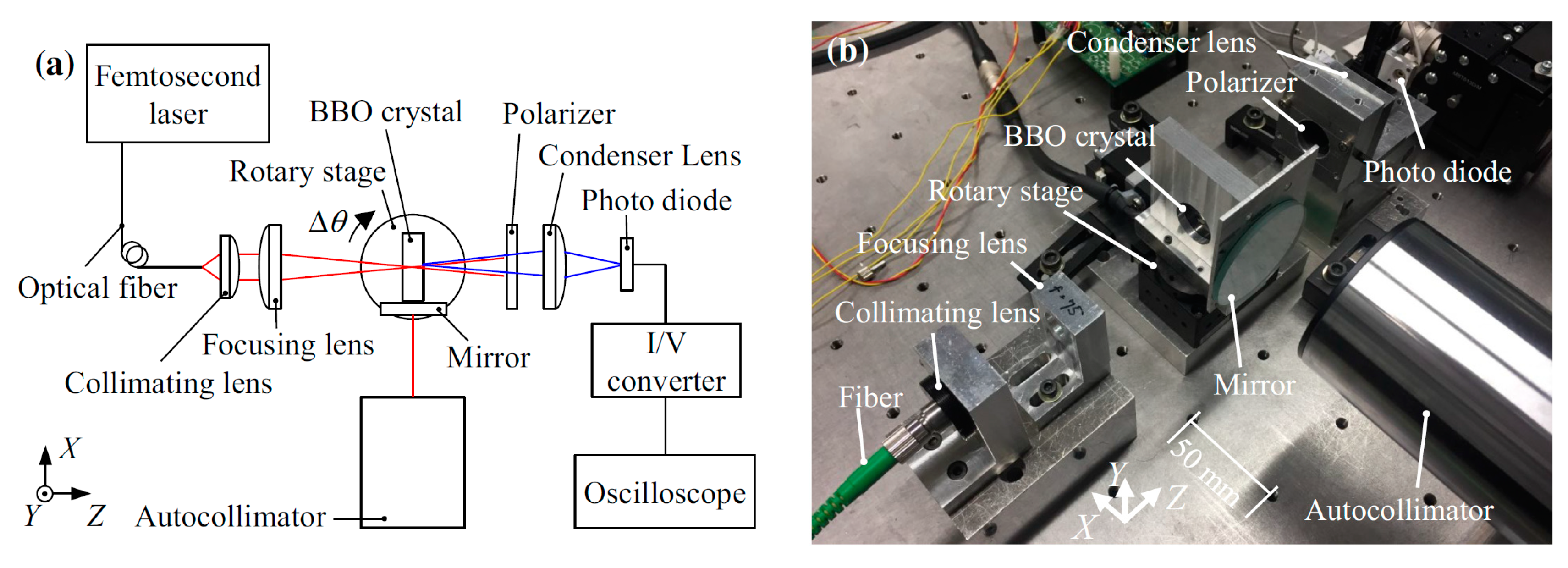
4. Angle Detection Based on the High Pulse Energy of a Mode-Locked Femtosecond Laser

The small angular displacement of an object can also be measured by utilizing the angle-dependency of the second harmonic generation (SHG) in nonlinear optics, where the second harmonic light with the doubled optical frequency ν2 = 2ν1 of the fundamental light ν1 incident to a nonlinear optical component is generated. It is well known that an efficient SHG can be accomplished by the procedure referred to as index matching [73], where the intensity of the second harmonic light depends on the angle of incidence of the fundamental light; this angle dependency can be employed for small angular displacement measurement. Owing to the characteristic of a mode-locked femtosecond laser with high pulse energy, effective SHG can be achieved by focusing a mode-locked femtosecond laser beam in a nonlinear crystal. On the assumption that the Rayleigh length b of the focused fundamental light lay with wavelength λ1 is much longer than the length of the negative uniaxial crystal with refractive indices of ne and no for extraordinary and ordinary rays, respectively, the intensity of the second harmonic light I2 with wavelength λ2 to be generated by SHG can be expressed as follows [59]:
I 2 = 8 π 2 d eff 2 L 2 n 1 2 n 2 ε 0 c λ 1 2 I 1 2 sin c 2 ( Δ k L / 2 )
where I1 is the light intensity of the fundamental light ray, deff is the effective nonlinear coefficient [32], ε0 is the vacuum permittivity, c is the speed of light in a vacuum. In the above Equation, Δk is a θ-dependent phase mismatching that can be represented as Δk = 4π[no(λ1) − ne(θ,λ2)]/λ1. The angle θ = θm satisfying the sinc-term in the above Equation to be the maximum value of 1 (namely, ne = no and Δk thus becomes zero) is referred to as the matching angle (Figure 16) that can be obtained by the following Equation [59]:
θ m = arcsin ( [ n O ( λ 1 ) ] 2 [ n O ( λ 2 ) ] 2 [ n e ( λ 1 ) ] 2 [ n O ( λ 2 ) ] 2 )
According to the above Equations, the intensity of the second-harmonic light I2 decreases rapidly with the small angular displacement of the nonlinear crystal from the matching angle; this characteristic of the SHG can be employed for angle measurement.
Figure 17a shows an example of how to apply the characteristic of the matching angle in SHG for measurement of the small angular displacement of an object [59]. In the setup, a nonlinear crystal is mounted on a rotary table. For angle measurement, the optic axis of the nonlinear crystal is aligned to have the angle θ, which is almost equal to the matching angle θm, with respect to the propagating direction of the fundamental light wave as shown in Figure 18b so that the second harmonic light with enough power can be obtained. A small angular displacement of the rotary table can be measured by detecting the angular displacement of the nonlinear crystal by monitoring the change in the intensity of the second harmonic light with a photodetector.
The feasibility of the method described above has been verified in experiments. Figure 18a,b show a schematic and a photograph of the developed setup. An Erbium-doped fiber-based mode-locked femtosecond laser with the spectrum ranging from 1480 nm to 1640 nm has been employed as the light source. The laser beam introduced into the setup is at first collimated by a collimating lens and is then made incident to a nonlinear crystal mounted on a rotary table. As can be seen in Equation (8), the intensity of the second harmonic light to be generated in a nonlinear crystal depends on the crystal material, as well as the light wavelength. In the setup, barium borate (BBO) crystal with a similar matching angle for each mode in the femtosecond laser has thus been employed as the nonlinear crystal. The optic axis of the nonlinear crystal is adjusted to be approximately 20 degrees. It should be noted that, regarding Equation (7), the fundamental light is made to focus in the BBO crystal so that the second harmonic light can be generated effectively. The second harmonic light generated by SHG is then condensed onto a photodiode by a condenser lens, and the photocurrent from the photodiode is converted into voltage signal through a trans-impedance amplifier to monitor the signal by an oscilloscope. It should be noted that not only the second harmonic light but also the remaining fundamental light would come out from the BBO crystal. In the setup, a polarizer is placed in front of the photodiode so that the fundamental light will not be detected. For the verification of the angular displacement of the BBO crystal, a commercial laser autocollimator is also employed as a reference sensor.
Figure 19a shows the change in the intensity of the second harmonic light as the change in the angular displacement of the BBO crystal observed in experiments, where three types of focusing lens with focal lengths of 40 mm, 75 mm and 150 mm are employed. As can be seen in the figure, a peak can be observed at the matching angle in each of the plots. Figure 19b shows the variation of the intensity of second-harmonic light as the change in the angular position of the BBO crystal. As can be seen in the figure, the angular displacement in a step of 0.4 arc-seconds has clearly been distinguished. These results demonstrate the feasibility of measuring small angular displacement by the SHG. It has also been verified that the shorter focal length of the focusing lens contributes to obtaining second-harmonic light with larger intensity, since the power of the fundamental beam can be further concentrated at the beam waist of the focused beam in the BBO crystal.

5. Conclusions

A mode-locked femtosecond laser has been employed in a variety of applications in dimensional metrology for production engineering. In recent years, mode-locked femtosecond lasers have expanded application to precision angle measurement, which is also an important activity in production engineering. In this article, some angle measurement techniques employing a mode-locked femtosecond laser have been reviewed. With the employment of the dispersive characteristic of diffraction grating, equally-spaced modes of the mode-locked femtosecond laser in frequency domain can be converted into the “angle scale comb”, which is a series of scale graduations for angle measurement. With the enhancement of the highly-stabilized optical modes of a mode-locked femtosecond laser over a wide spectral range, highly stable optical angle measurement can be achieved over a wide measuring range. In addition, by combining the angle scale comb with the laser autocollimation, a mode-locked femtosecond laser autocollimator with a high resolution over a wide angular range can be realized. The mode-locked femtosecond laser autocollimator has the possibility of realizing a direct link of angle measurement to the national standard of time/frequency by observing the reading output in the frequency domain. A mode-lock femtosecond laser can also be employed for angle measurement by utilizing physical phenomena such as the second harmonic generation of a nonlinear crystal or lateral chromatic aberration of a single lens. In addition, novel optical setups for the absolute distance measurement with a mode-locked femtosecond laser source can also achieve the measurement of angular displacement/absolute angular position of an object. Table 2 summarizes the features of the angle measurement techniques reviewed in this paper, including the achieved resolutions and measuring ranges.
One of the disadvantages of the above-mentioned techniques is the high cost of the mode-locked femtosecond laser source. With the decrease of the cost of the femtosecond laser source, the angle measurement techniques explained in this review article are expected to be employed in many industrial applications in the near future where the traceability of measurement becomes a more important issue to be addressed.

Author Contributions

Conceptualization, W.G. and Y.S.; methodology, W.G. and Y.S.; software, W.G. and Y.S.; validation, W.G. and Y.S.; formal analysis, W.G. and Y.S.; investigation, Y.S. and H.M.; resources, W.G. and Y.S.; data curation, W.G., H.M. and Y.S.; writing—original draft preparation, Y.S.; writing—review and editing, W.G. and Y.S.; visualization, Y.S. and W.G.; supervision, W.G.; project administration, W.G.; funding acquisition, W.G., Y.S. and H.M. All authors have read and agreed to the published version of the manuscript.

Funding

A part of this research is supported by the Japan Society for the Promotion of Science (JSPS) 15H05759 and 18H01345.

Acknowledgments

The authors would like to thank all our laboratory members who joined the related projects at Tohoku University for their contributions to the achievements described in this paper.

Conflicts of Interest

The authors declare no conflict of interest. The founding sponsors had no role in the design of the study; in the collection, analyses, or interpretation of data; in the writing of the manuscript, and in the decision to publish the results.

References

  1. ISO. Geometrical Product Specifications (GPS)—Dimensional tolerancing—Part 2: Dimensions Other than Linear Sizes; ISO 14405-2:2011; ISO: Genava, Switzerland, 2012. [Google Scholar]
  2. Gao, W.; Haitjema, H.; Fang, F.Z.; Leach, R.K.; Cheung, C.F.; Savio, E.; Linares, J.M. On-machine and in-process surface metrology for precision manufacturing. CIRP Ann. 2019, 68, 843–866. [Google Scholar] [CrossRef] [Green Version]
  3. Wallis, D.A. History of Angle Measurement. In Proceedings of the FIG Working Week 2005 and the 8th International Conference for Global Spatial Data Infrastructure, Cairo, Egypt, 16–21 April 2005; pp. 1–17. [Google Scholar]
  4. Gao, W. Precision Nanometrology—Sensors and Measuring Systems for Nanomanufacturing; Springer: Berlin/Heidelberg, Germany, 2010. [Google Scholar]
  5. Just, A.; Krause, M.; Probst, R.; Bosse, H.; Haunerdinger, H.; Spaeth, C.; Metz, G.; Israel, W. Comparison of angle standards with the aid of a high-resolution angle encoder. Precis. Eng. 2009, 33, 530–533. [Google Scholar] [CrossRef]
  6. Renishaw plc. RESOLUTE Absolute Optical Encoder with Biss Serial Communications; Renishaw plc: Wotton-under-Edge, UK, 2013; pp. 1–8. [Google Scholar]
  7. Magnescale, C. Feedback Scale General Catalog. Available online: http://www.magnescale.com/mgs/product/catalog/FeedbackScale_en.pdf (accessed on 29 May 2020).
  8. Miyashita, K.; Takahashi, T.; Yamanaka, M. Features of a magnetic rotary encoder. IEEE Trans. Magn. 1987, 23, 2182–2184. [Google Scholar] [CrossRef]
  9. Watanabe, T.; Kon, M.; Nabeshima, N.; Taniguchi, K. An angle encoder for super-high resolution and super-high accuracy using SelfA. Meas. Sci. Technol. 2014, 25, 065002. [Google Scholar] [CrossRef]
  10. Watanabe, T.; Fujimoto, H.; Masuda, T. Self-calibratable rotary encoder. J. Phys. Conf. Ser. 2005, 13, 240–245. [Google Scholar] [CrossRef]
  11. Gao, W.; Kim, S.W.; Bosse, H.; Haitjema, H.; Chen, Y.L.; Lu, X.D.; Knapp, W.; Weckenmann, A.; Estler, W.T.; Kunzmann, H. Measurement technologies for precision positioning. CIRP Ann. Manuf. Technol. 2015, 64, 773–796. [Google Scholar] [CrossRef]
  12. Kunzmann, H.; Pfeifer, T.; Flügge, J. Scales vs. Laser Interferometers Performance and Comparison of Two Measuring Systems. CIRP Ann. Manuf. Technol. 1993, 42, 753–767. [Google Scholar] [CrossRef]
  13. Cheng, F.; Fan, K.C. High-resolution angle measurement based on Michelson interferometry. Phys. Procedia 2011, 19, 3–8. [Google Scholar] [CrossRef] [Green Version]
  14. Moore, W.R. Foundations of Mechanical Accuracy; The Moore Special Tool Company: Bridgeport, CT, USA, 1970. [Google Scholar]
  15. Luther, G.G.; Deslattes, R.D.; Towler, W.R. Single axis photoelectronic autocollimator. Rev. Sci. Instrum. 1984, 55, 747–750. [Google Scholar] [CrossRef]
  16. Gao, W.; Ohnuma, T.; Satoh, H.; Shimizu, H.; Kiyono, S.; Makino, H. A precision angle sensor using a multi-cell photodiode array. CIRP Ann. Manuf. Technol. 2004, 53, 425–428. [Google Scholar] [CrossRef]
  17. Geckeler, R.D.; Just, A.; Krause, M.; Yashchuk, V.V. Autocollimators for deflectometry: Current status and future progress. Nucl. Instrum. Methods Phys. Res. Sect. A Accel. Spectrometers Detect. Assoc. Equip. 2010, 616, 140–146. [Google Scholar] [CrossRef] [Green Version]
  18. Geckeler, R.D.; Weingaertner, I.; Just, A.; Probst, R. Use and treaceable calibration of autocollimators for ultra-precise measurement of slope and topography. Recent Dev. Traceable Dimens. Meas. 2001, 4401, 184–195. [Google Scholar]
  19. Qian, S.; Geckeler, R.D.; Just, A.; Idir, M.; Wu, X. Approaching sub-50 nanoradian measurements by reducing the saw-tooth deviation of the autocollimator in the Nano-Optic-Measuring Machine. Nucl. Instrum. Methods Phys. Res. Sect. A Accel. Spectrometers Detect. Assoc. Equip. 2015, 785, 206–212. [Google Scholar] [CrossRef] [Green Version]
  20. Bitou, Y.; Kondo, Y. Scanning deflectometric profiler for measurement of transparent parallel plates. Appl. Opt. 2016, 55, 9282–9287. [Google Scholar] [CrossRef]
  21. Chen, M.; Xie, S.; Wu, H.; Takahashi, S.; Takamasu, K. Three-dimensional surface profile measurement of a cylindrical surface using a multi-beam angle sensor. Precis. Eng. 2020, 62, 62–70. [Google Scholar] [CrossRef]
  22. MÖLLER-WEDEL OPTICAL Electroninc Autocollimators. Available online: www.moeller-wedel-optical.com (accessed on 29 May 2020).
  23. Nikon Corporation Autocollimators 6B-LED/6D-LED. Available online: https://www.nikon.com/products/industrial-metrology/support/download/brochures/pdf/2ce-iwqh-4.pdf (accessed on 29 May 2020).
  24. Trioptics GmbH OptiTest (R) a Complete Range of Optical Instrument. Available online: http://www.trioptics.com (accessed on 29 May 2020).
  25. Ennos, A.E.; Virdee, M.S. High accuracy profile measurement of quasi-conical mirror surfaces by laser autocollimation. Precis. Eng. 1982, 4, 5–8. [Google Scholar] [CrossRef]
  26. Saito, Y.; Gao, W.; Kiyono, S. A single lens micro-angle sensor. Int. J. Precis. Eng. 2007, 8, 14–18. [Google Scholar]
  27. Shimizu, Y.; Tan, S.L.; Murata, D.; Maruyama, T.; Ito, S.; Chen, Y.-L.; Gao, W. Ultra-sensitive angle sensor based on laser autocollimation for measurement of stage tilt motions. Opt. Express 2016, 24, 2788–2805. [Google Scholar] [CrossRef]
  28. Gao, W.; Huang, P.S.; Yamada, T.; Kiyono, S. A compact and sensitive two-dimensional angle probe for flatness measurement of large silicon wafers. Precis. Eng. 2002, 26, 396–404. [Google Scholar] [CrossRef]
  29. Gao, W.; Saito, Y.; Muto, H.; Arai, Y.; Shimizu, Y. A three-axis autocollimator for detection of angular error motions of a precision stage. CIRP Ann. Manuf. Technol. 2011, 60, 515–518. [Google Scholar] [CrossRef]
  30. Li, X.; Gao, W.; Muto, H.; Shimizu, Y.; Ito, S.; Dian, S. A six-degree-of-freedom surface encoder for precision positioning of a planar motion stage. Precis. Eng. 2013, 37, 771–781. [Google Scholar] [CrossRef]
  31. Shimizu, Y.; Matsukuma, H.; Gao, W. Optical sensors for multi-axis angle and displacement measurement using grating reflectors. Sensors 2019, 19, 5289. [Google Scholar] [CrossRef] [PubMed] [Green Version]
  32. Matsukuma, H.; Ishizuka, R.; Furuta, M.; Li, X.; Shimizu, Y.; Gao, W. Reduction in Cross-Talk Errors in a Six-Degree-of-Freedom Surface Encoder. Nanomanuf. Metrol. 2019, 2, 111–123. [Google Scholar] [CrossRef]
  33. Gao, W.; Araki, T.; Kiyono, S.; Okazaki, Y.; Yamanaka, M. Precision nano-fabrication and evaluation of a large area sinusoidal grid surface for a surface encoder. Precis. Eng. 2003, 27, 289–298. [Google Scholar] [CrossRef]
  34. Shimizu, Y.; Kataoka, S.; Ishikawa, T.; Chen, Y.L.; Chen, X.; Matsukuma, H.; Gao, W. A liquid-surface-based three-axis inclination sensor for measurement of stage tilt motions. Sensors 2018, 18, 398. [Google Scholar] [CrossRef] [Green Version]
  35. Jones, D.J.; Cundiff, S.T.; Fortier, T.M.; Hall, J.L.; Ye, J. Carrier–Envelope Phase Stabilization of Single and Multiple Femtosecond Lasers. In Few-Cycle Laser Pulse Generation and Its Applications. Topics in Applied Physics; Kärtner, F.X., Ed.; Springer: Berlin/Heidelberg, Germany, 2012; Volume 95, pp. 317–343. [Google Scholar]
  36. Jones, D.J.; Diddams, S.A.; Ranka, J.K.; Stentz, A.; Windeler, R.S.; Hall, J.L.; Cundiff, S.T. Carrier-envelope phase control of femtosecond mode-locked lasers and direct optical frequency synthesis. Science 2000, 288, 635–640. [Google Scholar] [CrossRef] [Green Version]
  37. Udem, T.; Holzwarth, R.; Hänsch, T.W. Optical frequency metrology. Nature 2002, 416, 233–237. [Google Scholar] [CrossRef]
  38. Udem, T.; Reichert, J.; Holzwarth, R.; Hänsch, T.W. Accurate measurement of large optical frequency differences with a mode-locked laser. Opt. Lett. 1999, 24, 881–883. [Google Scholar] [CrossRef]
  39. Jang, Y.-S.; Kim, S.-W. Distance Measurements Using Mode-Locked Lasers: A Review. Nanomanuf. Metrol. 2018, 1, 131–147. [Google Scholar] [CrossRef]
  40. Minoshima, K.; Matsumoto, H. High-accuracy measurement of 240-m distance in an optical tunnel by use of a compact femtosecond laser. Appl. Opt. 2000, 39, 5512–5517. [Google Scholar] [CrossRef]
  41. Bitou, Y.; Schibli, T.R.; Minoshima, K. Accurate wide-range displacement measurement using tunable diode laser and optical frequency comb generator. Opt. Express 2006, 14, 644–654. [Google Scholar] [CrossRef]
  42. Kajima, M.; Matsumoto, H. Picometer positioning system based on a zooming interferometer using a femtosecond optical comb. Opt. Express 2008, 16, 1497–1506. [Google Scholar] [CrossRef]
  43. Joo, K.-N.; Kim, Y.; Kim, S.-W. Distance measurements by combined method based on a femtosecond pulse laser. Opt. Express 2008, 16, 19799–19806. [Google Scholar] [CrossRef]
  44. Bitou, Y. High-accuracy displacement metrology and control using a dual Fabry-Perot cavity with an optical frequency comb generator. Precis. Eng. 2009, 33, 187–193. [Google Scholar] [CrossRef]
  45. Coddington, I.; Swann, W.C.; Nenadovic, L.; Newbury, N.R. Rapid and precise absolute distance measurements at long range. Nat. Photonics 2009, 3, 351–356. [Google Scholar] [CrossRef]
  46. Kim, S.W. Metrology: Combs rule. Nat. Photonics 2009, 3, 313–314. [Google Scholar] [CrossRef]
  47. Bae, J.; Park, J.; Ahn, H.; Jin, J. Total physical thickness measurement of a multi-layered wafer using a spectral-domain interferometer with an optical comb. Opt. Express 2017, 25, 12689–12697. [Google Scholar] [CrossRef]
  48. Park, J.; Jin, J.; Wan Kim, J.; Kim, J.A. Measurement of thickness profile and refractive index variation of a silicon wafer using the optical comb of a femtosecond pulse laser. Opt. Commun. 2013, 305, 170–174. [Google Scholar] [CrossRef]
  49. Jin, J.; Kim, J.W.; Kim, J.A.; Eom, T.B. Thickness and refractive index measurement of a wafer based on the optical comb. Opt. InfoBase Conf. Pap. 2010, 18, 18339–18346. [Google Scholar]
  50. Kubina, P.; Adel, P.; Adler, F.; Grosche, G.; Hänsch, T.W.; Holzwarth, R.; Leitenstorfer, A.; Lipphardt, B.; Schnatz, H. Long term comparison of two fiber based frequency comb systems. Opt. Express 2005, 13, 904–909. [Google Scholar] [CrossRef]
  51. Adler, F.; Moutzouris, K.; Leitenstorfer, A.; Schnatz, H.; Lipphardt, B.; Grosche, G.; Tauser, F. Phase-locked two-branch erbium-doped fiber laser system for long-term precision measurements of optical frequencies. Opt. Express 2004, 12, 5872–5880. [Google Scholar] [CrossRef] [PubMed]
  52. Hundertmark, H.; Wandt, D.; Fallnich, C.; Haverkamp, N.; Telle, H.R. Phase-locked carrier-envelope-offset frequency at 1560 nm. Opt. Express 2004, 12, 770–775. [Google Scholar] [CrossRef] [PubMed]
  53. Inaba, H.; Daimon, Y.; Hong, F.-L.; Onae, A.; Minoshima, K.; Schibli, T.R.; Matsumoto, H.; Hirano, M.; Okuno, T.; Onishi, M.; et al. Long-term measurement of optical frequencies using a simple, robust and low-noise fiber based frequency comb. Opt. Express 2006, 14, 5223–5231. [Google Scholar] [CrossRef] [PubMed]
  54. Shimizu, Y.; Kudo, Y.; Chen, Y.L.; Ito, S.; Gao, W. An optical lever by using a mode-locked laser for angle measurement. Precis. Eng. 2017, 47, 72–80. [Google Scholar] [CrossRef]
  55. Chen, Y.-L.; Shimitzu, Y.; Kudo, Y.; Ito, S.; Gao, W. Mode-locked laser autocollimator with an expanded measurement range. Opt. Express 2016, 24, 425–428. [Google Scholar] [CrossRef] [PubMed]
  56. Chen, Y.; Shimizu, Y.; Tamada, J.; Kudo, Y.; Madokoro, S.; Nakamura, K.; Gao, W.; Gao, W.; Kim, S.W.; Bosse, H.; et al. Optical frequency domain angle measurement in a femtosecond laser autocollimator. Opt. Express 2017, 25, 16725–16738. [Google Scholar] [CrossRef] [PubMed]
  57. Chen, Y.L.; Shimizu, Y.; Tamada, J.; Nakamura, K.; Matsukuma, H.; Chen, X.; Gao, W. Laser autocollimation based on an optical frequency comb for absolute angular position measurement. Precis. Eng. 2018, 54, 284–293. [Google Scholar] [CrossRef]
  58. Shimizu, Y.; Madokoro, S.; Matsukuma, H.; Gao, W. An optical angle sensor based on chromatic dispersion with a mode-locked laser source. J. Adv. Mech. Des. Syst. Manuf. 2018, 12. [Google Scholar] [CrossRef]
  59. Matsukuma, H.; Madokoro, S.; Dwi, W.; Yuki, A.; Wei, S. A New Optical Angle Measurement Method Based on Second Harmonic Generation with a Mode—Locked Femtosecond Laser. Nanomanuf. Metrol. 2019, 2, 187–198. [Google Scholar] [CrossRef]
  60. Dennis, M.L.; Diels, J.-C.M.; Lai, M. Femtosecond ring dye laser: A potential new laser gyro. Opt. Lett. 1991, 16, 529–531. [Google Scholar] [CrossRef]
  61. Diddams, S.; Atherton, B.; Diels, J.C. Frequency locking and unlocking in a femtosecond ring laser with application to intracavity phase measurements. Appl. Phys. B Lasers Opt. 1996, 63, 473–480. [Google Scholar] [CrossRef]
  62. Liang, X.; Lin, J.; Yang, L.; Wu, T.; Liu, Y.; Zhu, J. Simultaneous Measurement of Absolute Distance and Angle Based on Dispersive Interferometry. IEEE Photonics Technol. Lett. 2020, 32, 449–452. [Google Scholar] [CrossRef]
  63. Han, S.; Kim, Y.-J.; Kim, S.-W. Parallel determination of absolute distances to multiple targets by time-of-flight measurement using femtosecond light pulses. Opt. Express 2015, 23, 25874–25882. [Google Scholar] [CrossRef] [PubMed] [Green Version]
  64. Post, E.J. Sagnac effect. Rev. Mod. Phys. 1967, 39, 475–493. [Google Scholar] [CrossRef]
  65. Bergh, R.A.; Lefevre, H.C.; Shaw, H.J. An Overview of Fiber-optic Gyroscopes. J. Light. Technol. 1984, 2, 91–107. [Google Scholar] [CrossRef]
  66. Culshaw, B. Fibre optic gyroscopes. Phys. Technol. 1982, 13, 79–80. [Google Scholar] [CrossRef]
  67. Ezekiel, S.; Balsamo, S.R. Passive ring resonator laser gyroscope. Appl. Phys. Lett. 1977, 30, 478–480. [Google Scholar] [CrossRef]
  68. Kadiwar, R.K.; Giles, I.P. Optical Fibre Brillouin Ring Laser Gyroscope. Electron. Lett. 1989, 25, 1729–1731. [Google Scholar] [CrossRef]
  69. Rosker, M.J.; Christian, W.R.; Mcmichael, I.C.; Oaks, T. Picosecond-pulsed diode ring laser gyroscope. Proc. SPIE 1994, 2116, 365–373. [Google Scholar]
  70. Fortier, T.; Baumann, E. 20 Years of Developments in Optical Frequency Comb Technology and Applications. Commun. Phys. 2019, 2, 1–16. [Google Scholar] [CrossRef]
  71. Tausenev, A.V.; Kryukov, P.G.; Bubnov, M.M.; Likhachev, M.E.; Romanova, E.Y.; Yashkov, M.V.; Khopin, V.F.; Salganskii, M.Y. Efficient source of femtosecond pulses and its use for broadband supercontinuum generation. Kvantovaya Elektron. 2005, 35, 581–585. [Google Scholar] [CrossRef]
  72. Tamada, J.; Kudo, Y.; Chen, Y.-L.; Shimizu, Y.; Gao, W. Determination of the zero-position for an optical angle sensor. J. Adv. Mech. Des. Syst. Manuf. 2016, 10. [Google Scholar] [CrossRef] [Green Version]
  73. Hecht, E. Optics, 5th ed.; Pearson: London, UK, 2017; ISBN 9780133977226. [Google Scholar]
  74. Acosta, D.; Albajez, J.A.; Yagüe-Fabra, J.A.; Velázquez, J. Verification of Machine Tools Using Multilateration and a Geometrical Approach. Nanomanuf. Metrol. 2018, 1, 39–44. [Google Scholar] [CrossRef]
  75. Shiou, F.J.; Liu, M.X. Development of a novel scattered triangulation laser probe with six linear charge-coupled devices (CCDs). Opt. Lasers Eng. 2009, 47, 7–18. [Google Scholar] [CrossRef]
  76. Fan, K.C.; Chen, M.J. 6-Degree-of-freedom measurement system for the accuracy of X-Y stages. Precis. Eng. 2000, 24, 15–23. [Google Scholar] [CrossRef]
  77. Pellegrini, S.; Buller, G.S.; Smith, J.M.; Wallace, A.M.; Cova, S. Laser-based distance measurement using picosecond resolution time-correlated single-photon counting. Meas. Sci. Technol. 2000, 11, 712–716. [Google Scholar] [CrossRef]
  78. Cui, M.; Zeitouny, M.G.; Bhattacharya, N.; van den Berg, S.A.; Urbach, H.P. Long distance measurement with femtosecond pulses using a dispersive interferometer. Opt. Express 2011, 19, 6549–6562. [Google Scholar] [CrossRef] [PubMed] [Green Version]
  79. Joo, K.N.; Kim, S.W. Absolute distance measurement by dispersive interferometry using a femtosecond pulse laser. Opt. Express 2006, 14, 5954–5960. [Google Scholar] [CrossRef]
Figure 1. Angle scale comb generated from the equally-spaced optical modes of a mode-locked femtosecond laser in the frequency domain with the enhancement of the dispersive characteristics of a reflective-type diffraction grating [54].
Applsci 10 04047 g001
Figure 2. Applications of the angle scale comb [54]: (a) Measurement of the angular displacement of a rotary table; (b) Measurement of the surface form of an optical component.
Applsci 10 04047 g002
Figure 3. A comparison between the conventional laser autocollimator and the femtosecond laser autocollimator [55]: (a) A laser autocollimator with a single-mode laser source; (b) A femtosecond laser autocollimator with a mode-locked femtosecond laser source.
Applsci 10 04047 g003
Figure 4. Optical setup of the mode-locked femtosecond laser autocollimator [55]: (a) A schematic of the optical setup; (b) A photograph of the optical setup.
Applsci 10 04047 g004
Figure 5. Variation of the reading output of the femtosecond laser autocollimator due to the angular displacement of the grating reflector [55].
Applsci 10 04047 g005
Figure 6. Mode-locked femtosecond laser autocollimator based on the optical frequency-domain angle measurement [56].
Applsci 10 04047 g006
Figure 7. Femtosecond laser autocollimator based on the principle of the optical frequency-domain angle measurement [56].
Applsci 10 04047 g007
Figure 8. Reading output of the mode-locked femtosecond laser autocollimator with a visibility of 100% observed in the optical frequency domain [56].
Applsci 10 04047 g008
Figure 9. Absolute angular position measurement by the mode-locked femtosecond laser autocollimator based on the principle of the optical frequency-domain angle measurement with the enhancement of an assisted angle sensor [57]. In the setup, the angle of the normal of the grating reflector with respect to the incident femtosecond laser is a final measurand.
Applsci 10 04047 g009
Figure 10. An example of the absolute angular position measurement by the optical frequency-domain femtosecond laser autocollimator [57].
Applsci 10 04047 g010
Figure 11. Optical setup for measurement of the small angular displacement of an object based on the chromatic aberrations of a simple lens [58].
Applsci 10 04047 g011
Figure 12. Optical modes captured in the setup based on the chromatic aberrations of a simple lens [58]: (a) Variation of the light intensities of optical modes captured by the fiber detector; (b) Peak optical frequency detected at each angular position of the mirror reflector.
Applsci 10 04047 g012
Figure 13. An example of the angle measurement based on the absolute distance measurement [63].
Applsci 10 04047 g013
Figure 14. Dynamic measurement of the absolute angular position of an object by a dual-comb based absolute distance measurement method [63]: (a) Measured absolute distances of the four measurement points; (b) Variations of the absolute angular positions calculated from the measured absolute distances.
Applsci 10 04047 g014
Figure 15. Angle measurement based on the absolute distance measurement by a Michaelson interferometer with a mode-locked femtosecond laser source [62]: (a) Optical configuration with two measurement arms; (b) Spectrum of the combined beams.
Applsci 10 04047 g015
Figure 16. The matching angle in the second harmonic generation (SHG) [59]: (a) Refractive index ellipse of a negative uniaxial crystal; (b) Phase mismatched case; (c) Phase matched case.
Applsci 10 04047 g016
Figure 17. Measurement of the angular displacement of an object based on the characteristics of the matching angle in the second harmonic generation (SHG) [59]: (a) Schematic of the optical setup; (b) The angle to be measured by the method.
Applsci 10 04047 g017
Figure 18. Measurement of the angular displacement of a rotary table based on SHG: (a) Optical configuration of the setup; (b) A photograph of the setup [59].
Applsci 10 04047 g018
Figure 19. Variation of the light intensity of generated second harmonic light observed in experiments [59]: (a) Angle dependency of the second harmonic generation; (b) Variation of the light intensity of second harmonic light due to the angular displacement of the BBO crystal in a step of 0.4 arc-seconds.
Applsci 10 04047 g019
Table 1. Optical angle sensors based on a mode-locked femtosecond laser.
Utilized CharacteristicsPhysical Phenomenon/Measuring Technique to be Coupled
Stable discrete modes in frequency domain➢  Diffraction [54]
➢  Diffraction and laser autocollimation [55,56,57]
➢  Chromatic aberration [58]
➢  Sagnac effect [60,61] (Fiber optic gyroscope)
➢  Dispersive interferometry [62] (Absolute distance measurement)
High pulse energy➢  Time-of-flight (TOF) counted by dual-comb interferometry with balanced cross-correlation of second harmonics [63] (Absolute distance measurement)
➢  Second-harmonic generation (SHG) [59]
Table 2. Comparison of the techniques reviewed in this paper.
Type of the Optical Angle SensorResolution and Measuring RangeFeatures
(Advantages and Disadvantages)
Light intensity detecting-type mode-locked femtosecond laser autocollimator
(in Section 2.1.2) [55]
Resolution:
Sub-arc-second
Range:
>3°
➢  High measurement throughput with a high-speed photodetector
➢  A grating reflector required
➢  Low signal visibility
➢  The resolution is mainly limited by the wavelength resolution of the spectrometer in the detector unit
Frequency-domain mode-locked femtosecond laser autocollimator
(in Section 2.1.3) [56,57]
Resolution:
0.03 arc-seconds
Range:
>6°
➢  High signal visibility with a spectrometer that enables measurement of an object with low surface reflectivity
➢  A grating reflector required
➢  Low measurement throughput
➢  The resolution mainly limited by the wavelength resolution of the spectrometer in the detector unit
A method based on the chromatic aberration of a simple lens
(in Section 2.2) [58]
Resolution:
0.23 arc-seconds
Range:
>100 arc-seconds
➢  Simple optical configuration without a grating reflector
➢  High signal visibility with a spectrometer
➢  The resolution mainly limited by the chromatic lens and the wavelength resolution of the spectrometer in the detector unit
Methods based on the absolute distance measurement
(in Section 3) [63]
Resolution:
0.073 arc-seconds
Range:
>300 arc-seconds
➢  Long working distance
➢  High measurement throughput with a high-speed photodetector
➢  Several mirror reflectors are required
➢  The resolution mainly affected by environmental fluctuations (temperature, humidity, air pressure)
A method based on the second harmonic generation
(in Section 4) [59]
Resolution:
0.4 arc-seconds
Range:
>3.3°
➢  High measurement throughput with a high-speed photodetector
➢  An expensive nonlinear crystal required
➢  Limited applications (need to mount a nonlinear crystal for angle measurement)

