Adaptive Sensor Array Error Calibration Based Impact Localization on Composite Structure


Abstract
:1. Introduction
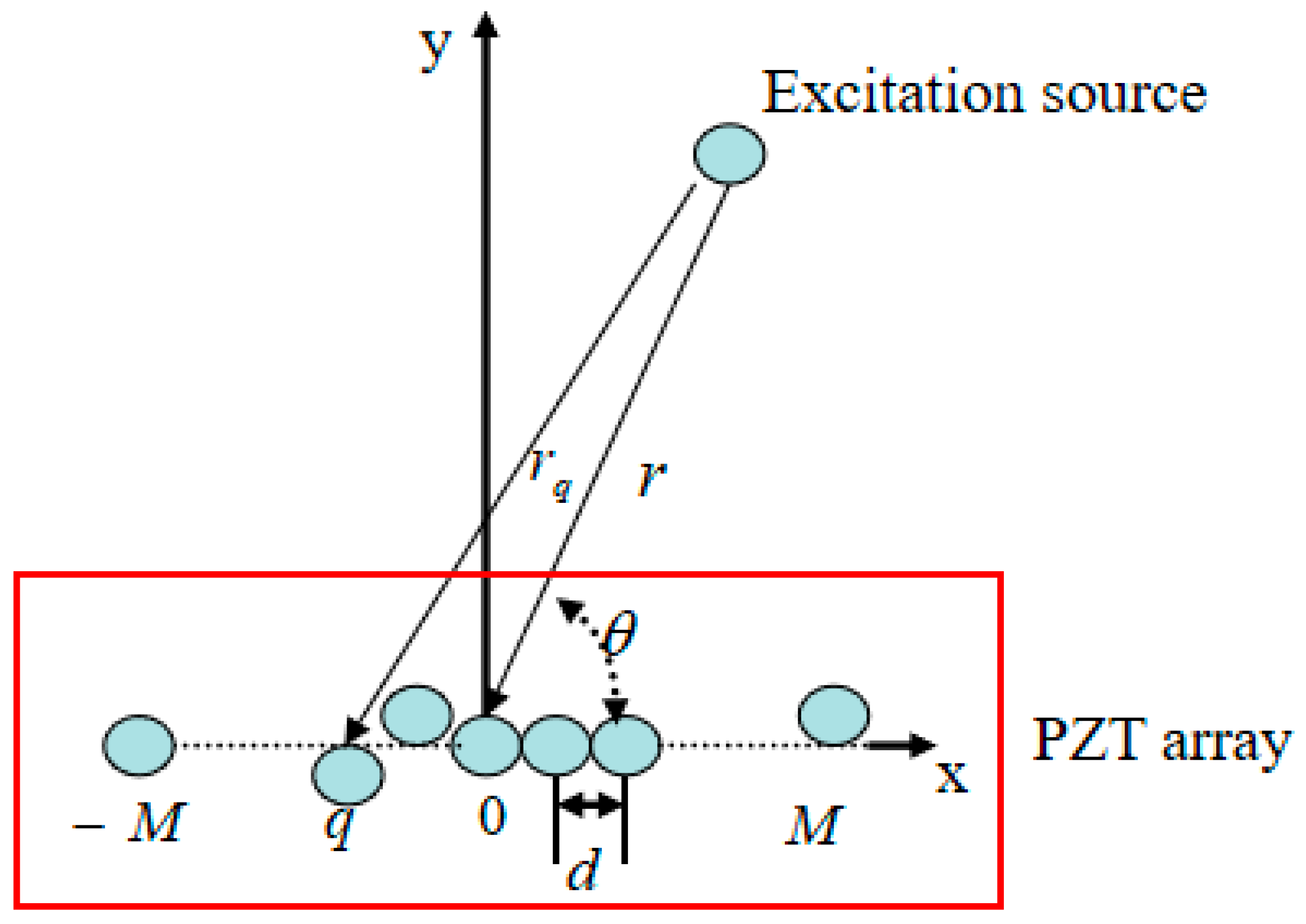
2. Signal Modal of Imprecise Sensor Array
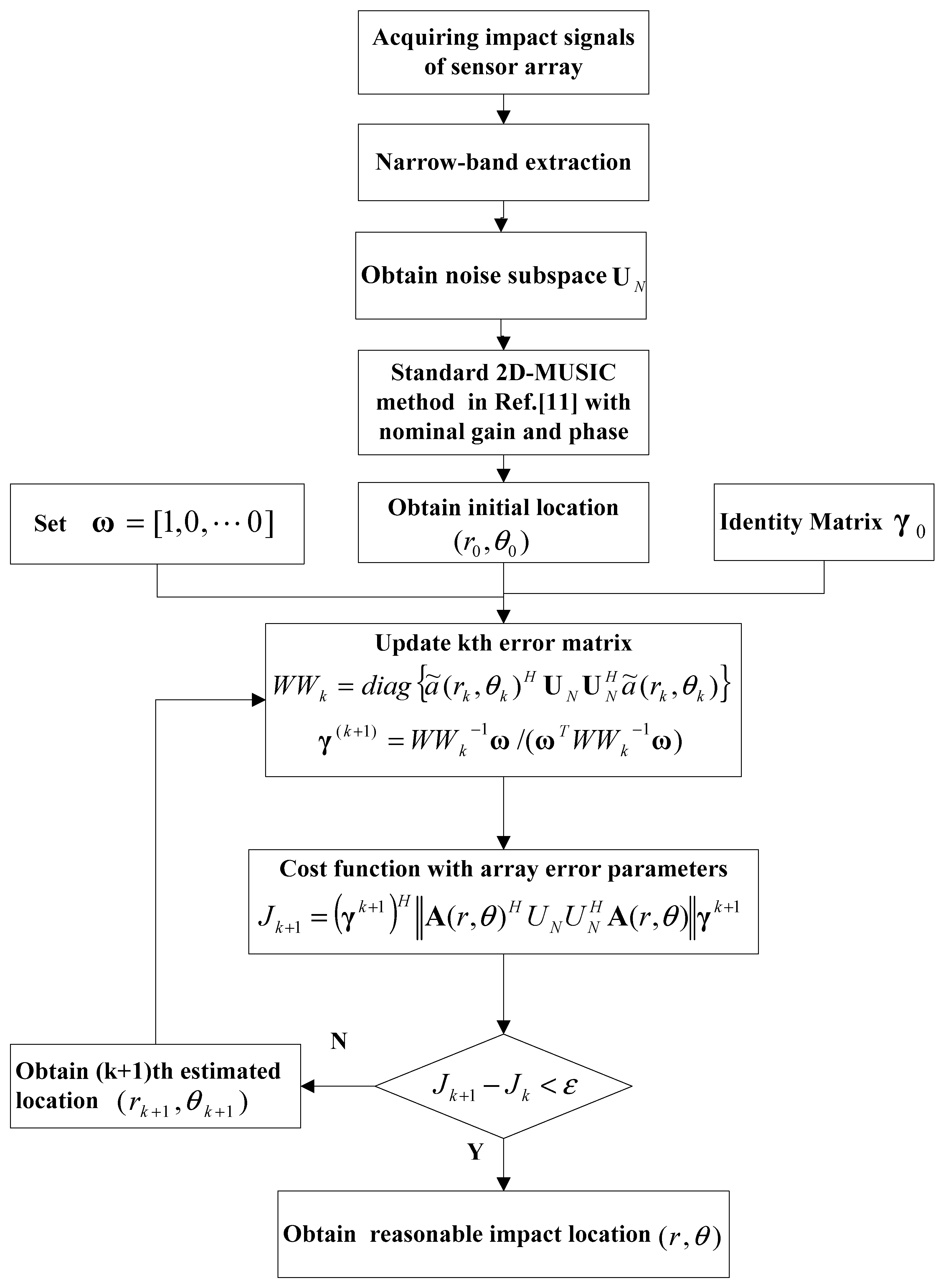
Adaptive Piezoelectric Sensor Array Error Calibration Based 2D-MUSIC
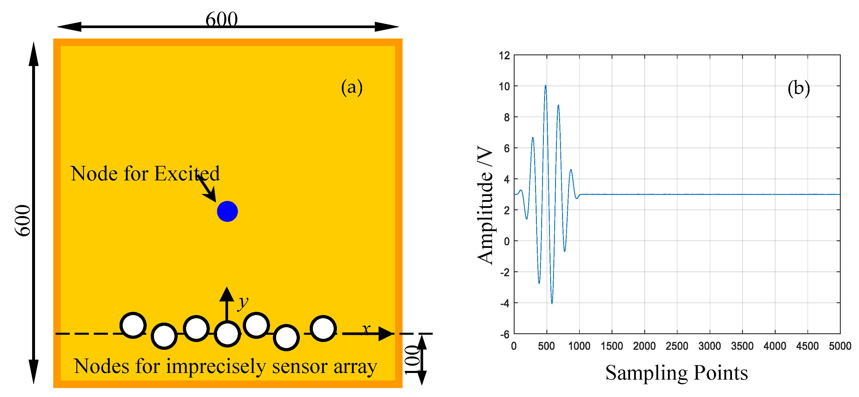
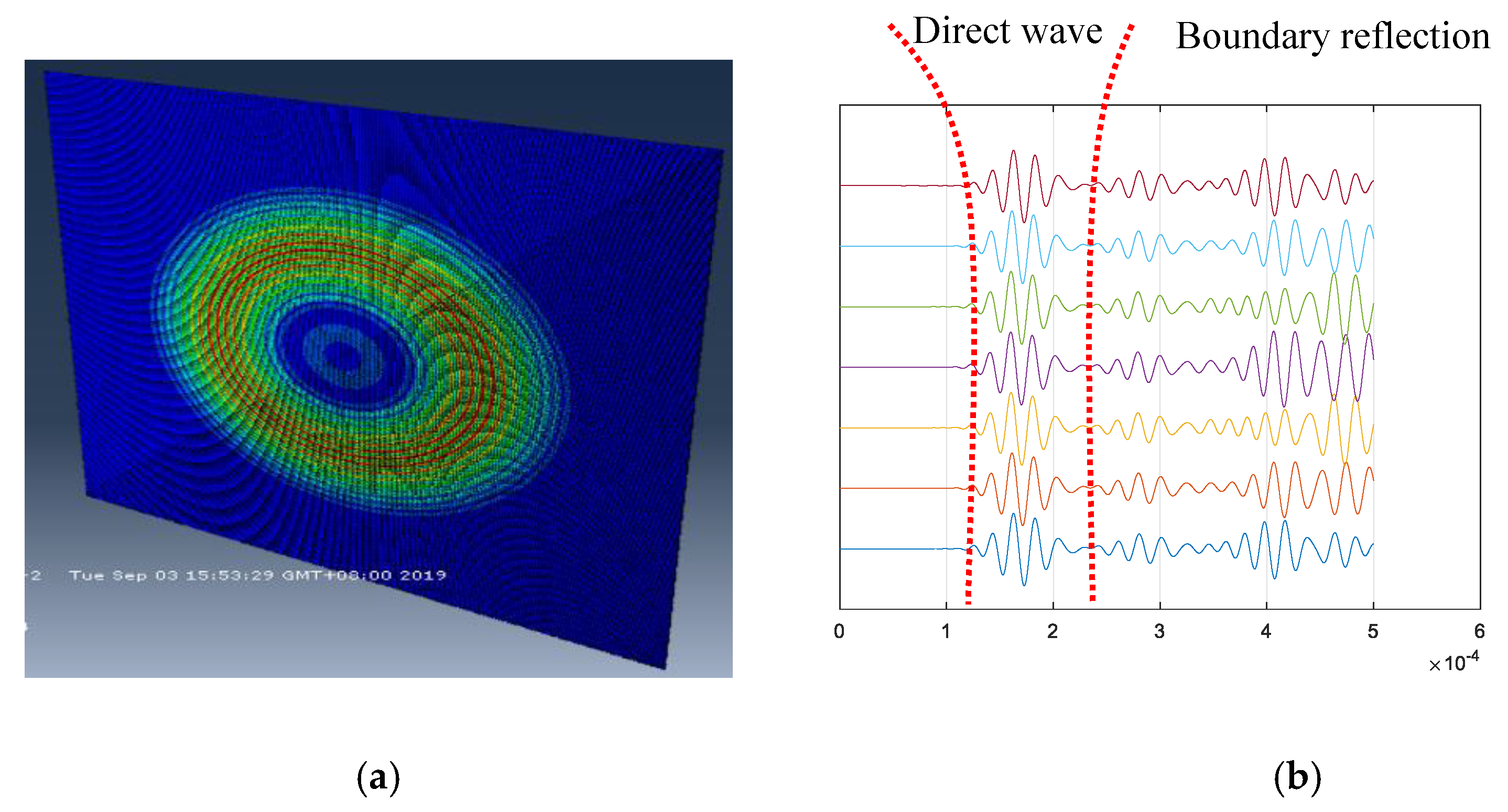
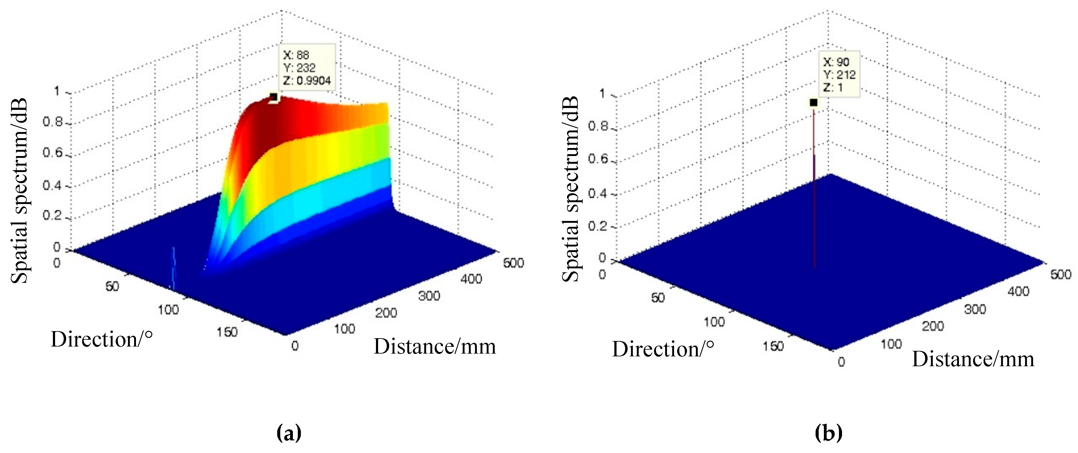
3. Finite Element Simulation
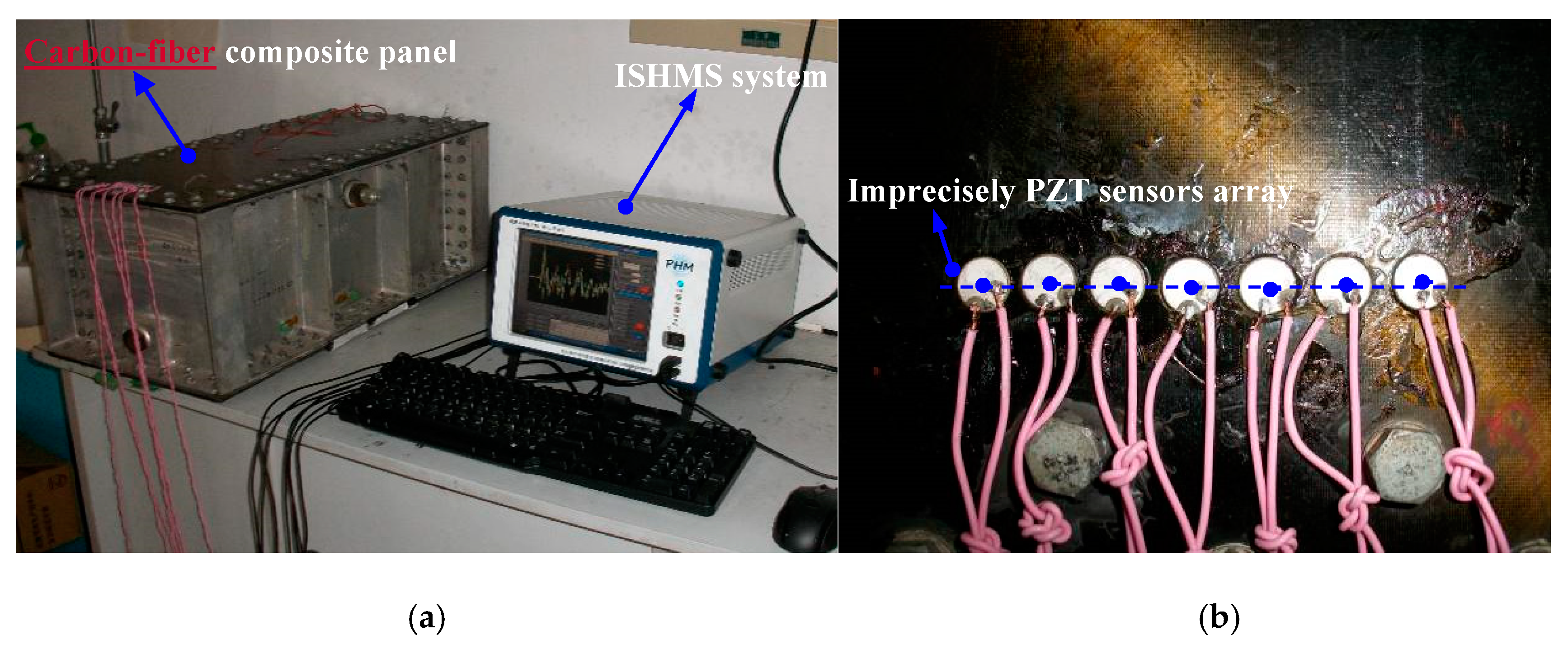
4. Evaluation on Carbon-Fiber Composite Panel
4.1. Experimental Setup
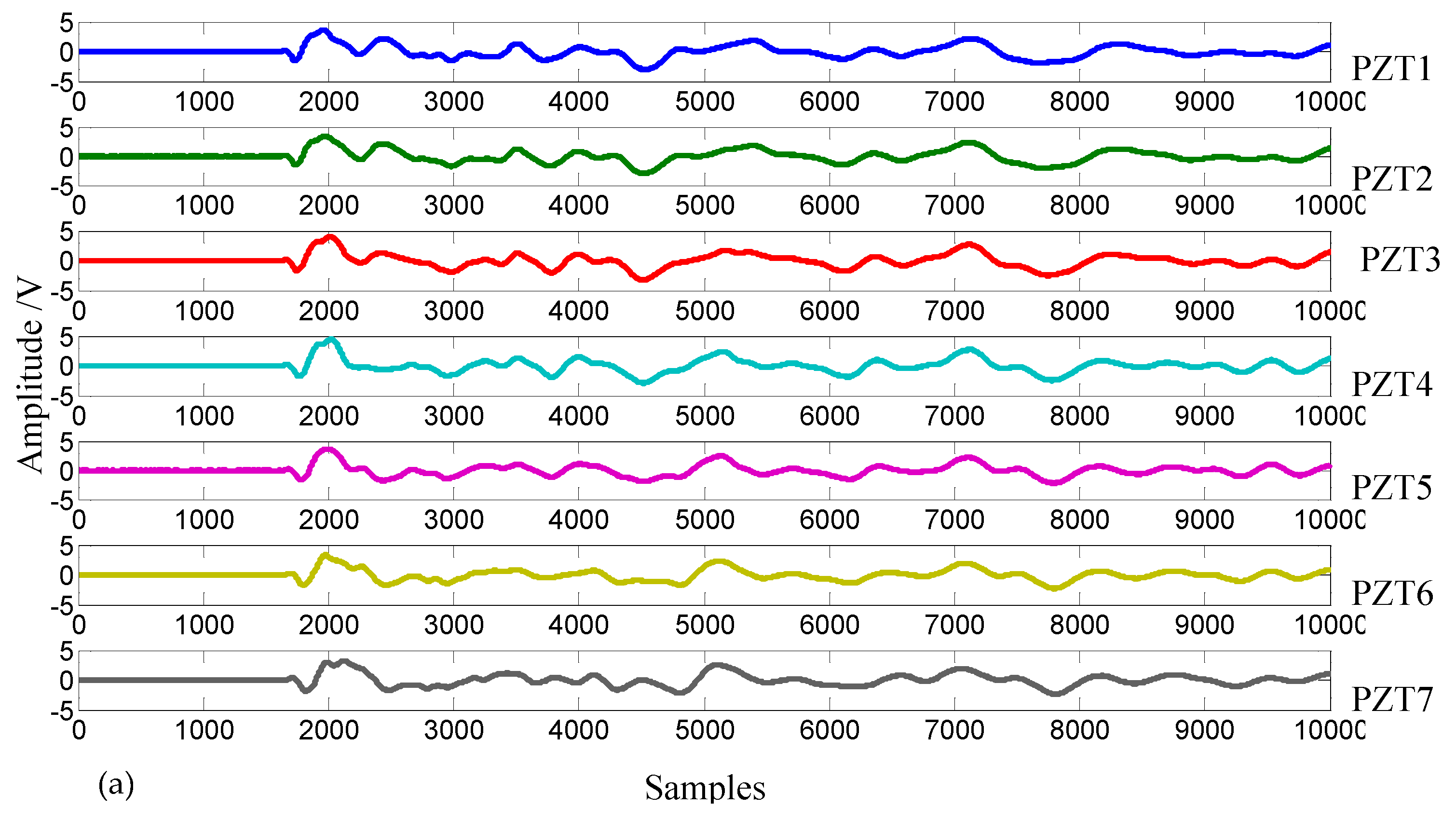
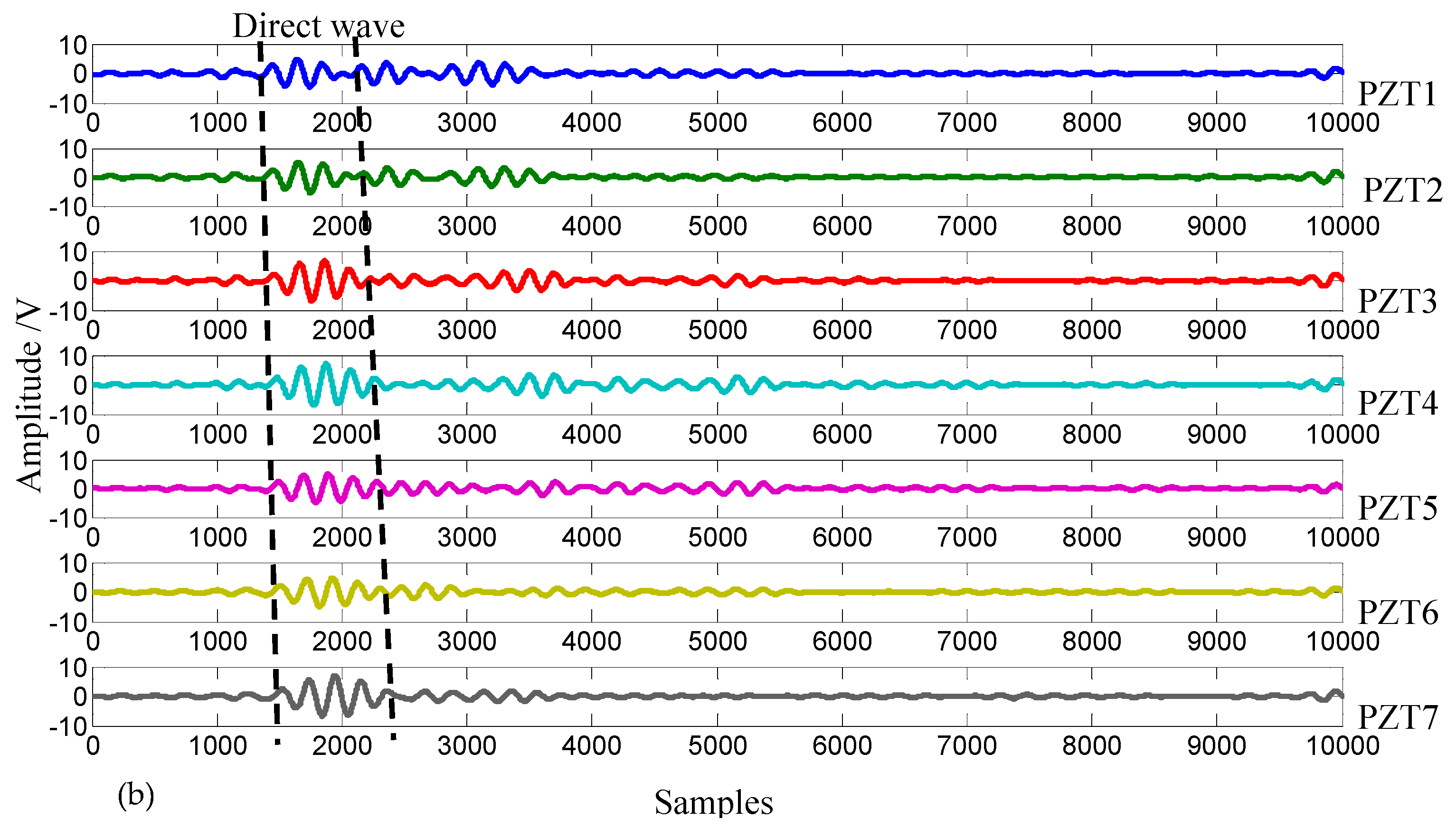
4.2. Impact Localization Results
5. Conclusions
Author Contributions
Funding
Conflicts of Interest
References
- Gorgin, R.; Luo, Y.; Wu, Z. Environmental and operational conditions effects on Lamb wave based structural health monitoring systems: A. review. Ultrasonics 2020, 105, 106114. [Google Scholar] [CrossRef] [PubMed]
- Ono, K. Review on structural health evaluation with acoustic emission. Appl. Sci. 2020, 8, 958. [Google Scholar] [CrossRef] [Green Version]
- Toh, G.; Park, J. Review of vibration-based structural health monitoring using deep learning. Appl. Sci. 2020, 10, 1680. [Google Scholar] [CrossRef]
- Talreja, R.; Phan, N. Assessment of damage tolerance approaches for composite aircraft with focus on barely visible impact damage. Compos. Struct. 2019, 219, 1–7. [Google Scholar] [CrossRef]
- Saeedifar, M.; Mansvelder, J.; Mohammadi, R.; Zarouchas, D. Using passive and active acoustic methods for impact damage assessment of composite structures. Compos. Struct. 2019, 226, UNSP 111252. [Google Scholar] [CrossRef] [Green Version]
- Qiu, L.; Bin, L.; Yuan, S.F.; Su, Z.Q. Impact imaging of aircraft composite structure based on a model-independent spatial-wavenumber filter. Ultrasonics 2016, 64, 10–24. [Google Scholar] [CrossRef] [PubMed]
- Wilcox, P.D. Omni-directional guided wave transducer arrays for the rapid inspection of large areas of plate structures. IEEE Trans. Ultrason. Ferroelectr. Freq. Control. 2003, 50, 699–709. [Google Scholar] [CrossRef] [PubMed]
- Schmidt, R.O. Multiple emitter location and signal parameter estimation. IEEE Trans. Antennas Propag. 1986, 34, 276–280. [Google Scholar] [CrossRef] [Green Version]
- Yang, H.; Lee, Y.J.; Lee, S.K. Impact source localization in plate utilizing multiple signal classification. Proc. Inst. Mech. Eng. Part C—J. Mech. Eng. Sci. 2013, 227, 703–713. [Google Scholar] [CrossRef]
- He, J.Z.; Yuan, F.G. Lamb wave-based subwavelength damage imaging using the DORT-MUSIC technique in metallic plates. Struct. Health Monit. 2016, 15, 65–80. [Google Scholar] [CrossRef]
- Yuan, S.F.; Zhong, Y.T.; Qiu, L.; Wang, Z.L. Two-dimensional near-field multiple signal classification algorithm–based impact localization. J. Intell. Mater. Syst. Struct. 2015, 26, 400–413. [Google Scholar] [CrossRef]
- Zhong, Y.T.; Xiang, J.W. A two-dimensional plum-blossom sensor array-based multiple signal classification method for impact localization in composite structures. Comput. Aided Civ. Infrastruct. Eng. 2016, 31, 633–643. [Google Scholar] [CrossRef]
- Zhong, Y.T.; Xiang, J.W.; Chen, X.Y.; Jiang, Y.Y.; Pang, J.H. Multiple signal classification-based impact localization in composite structures using optimized ensemble empirical mode decomposition. Appl. Sci. 2018, 8, 1447. [Google Scholar] [CrossRef] [Green Version]
- Zuo, H.; Yang, Z.; Xu, C.; Tian, S.; Chen, X. Damage identification for plate-like structures using ultrasonic guided wave based on improved MUSIC method. Compos. Struct. 2018, 203, 164–171. [Google Scholar] [CrossRef]
- Bao, Q.; Yuan, S.F.; Wang, Y.W.; Qiu, L. Anisotropy compensated MUSIC algorithm based composite structure damage imaging method. Compos. Struct. 2019, 214, 293–303. [Google Scholar] [CrossRef]
- Steinberg, B.D. Principles of Aperture and Array System Design Including Random and Adaptive Array; Wiley: New York, NY, USA, 1976. [Google Scholar]
- Jeong, H. Analysis of plate wave propagation in anisotropic laminates using a wavelet transform. NDTE Int. 2001, 34, 185–190. [Google Scholar] [CrossRef]


| Sensor Array | Sensor #1 | Sensor #2 | Sensor #3 | Sensor #4 | Sensor #5 | Sensor #6 | Sensor #7 |
|---|---|---|---|---|---|---|---|
| Precisely | (−30, 100) | (−20, 100) | (−10, 100) | (0, 100) | (10, 100) | (20, 100) | (30, 100) |
| Imprecisely | (−30, 104) | (−22, 98) | (−10, 100) | (2, 100) | (10, 100) | (18, 100) | (30, 100) |
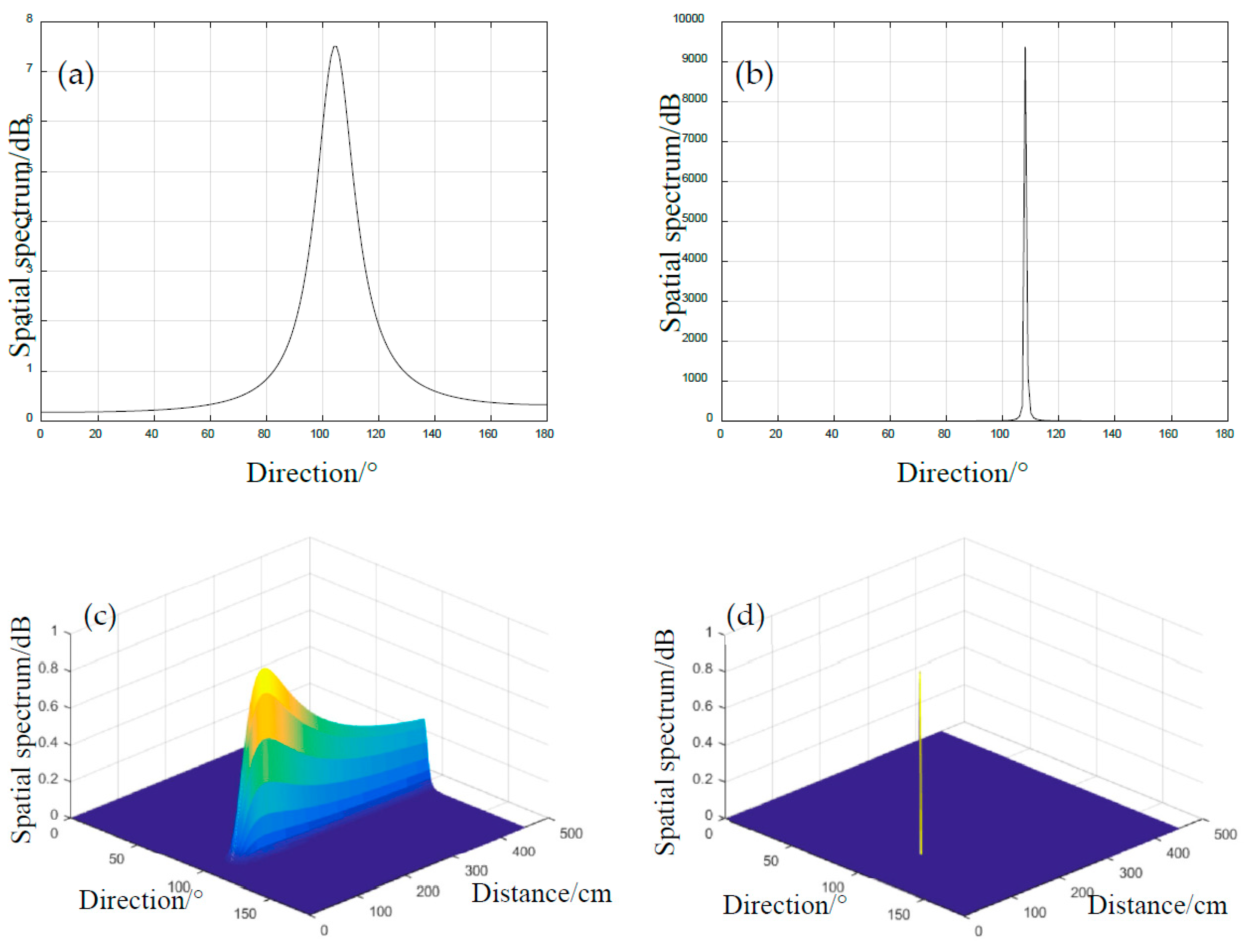
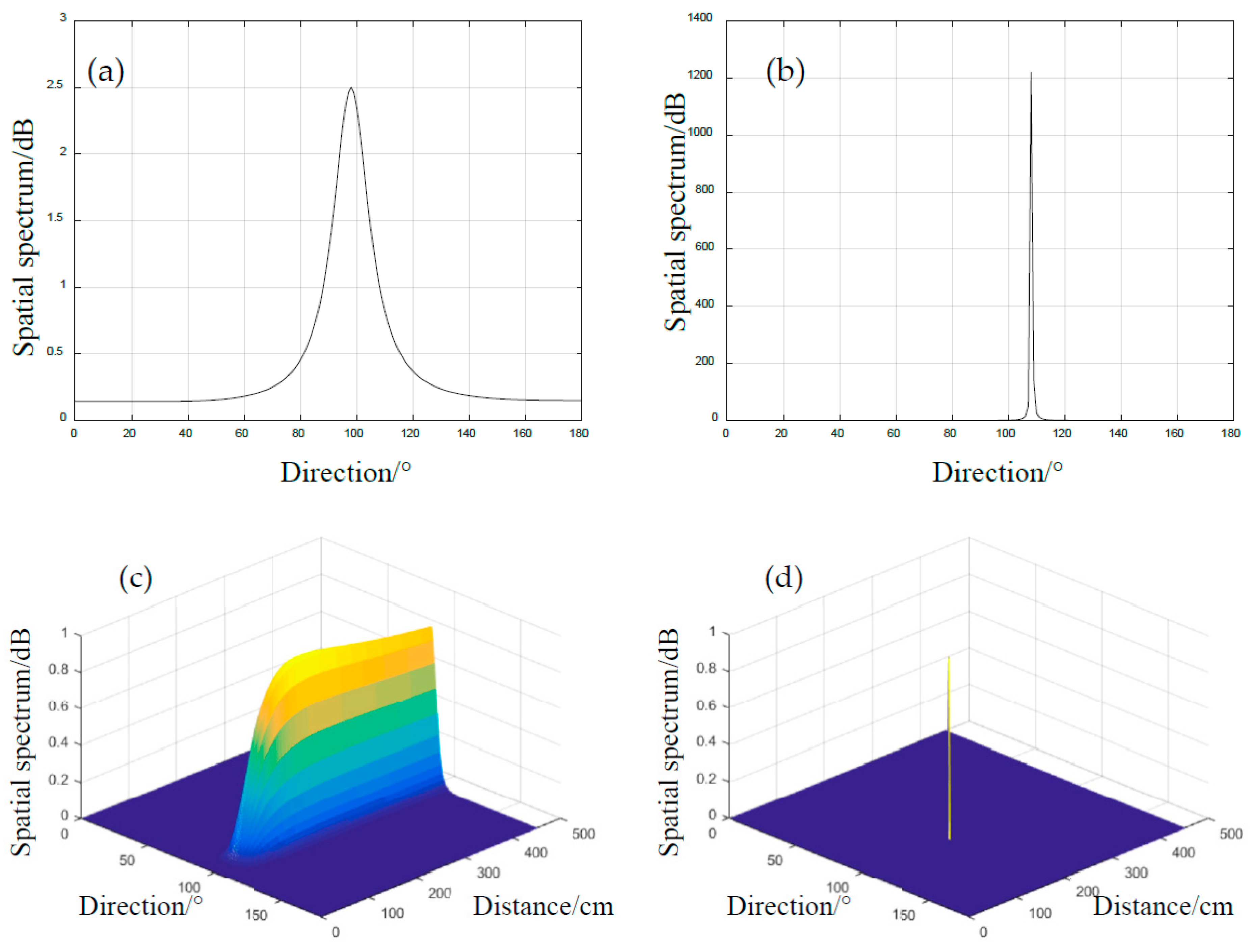
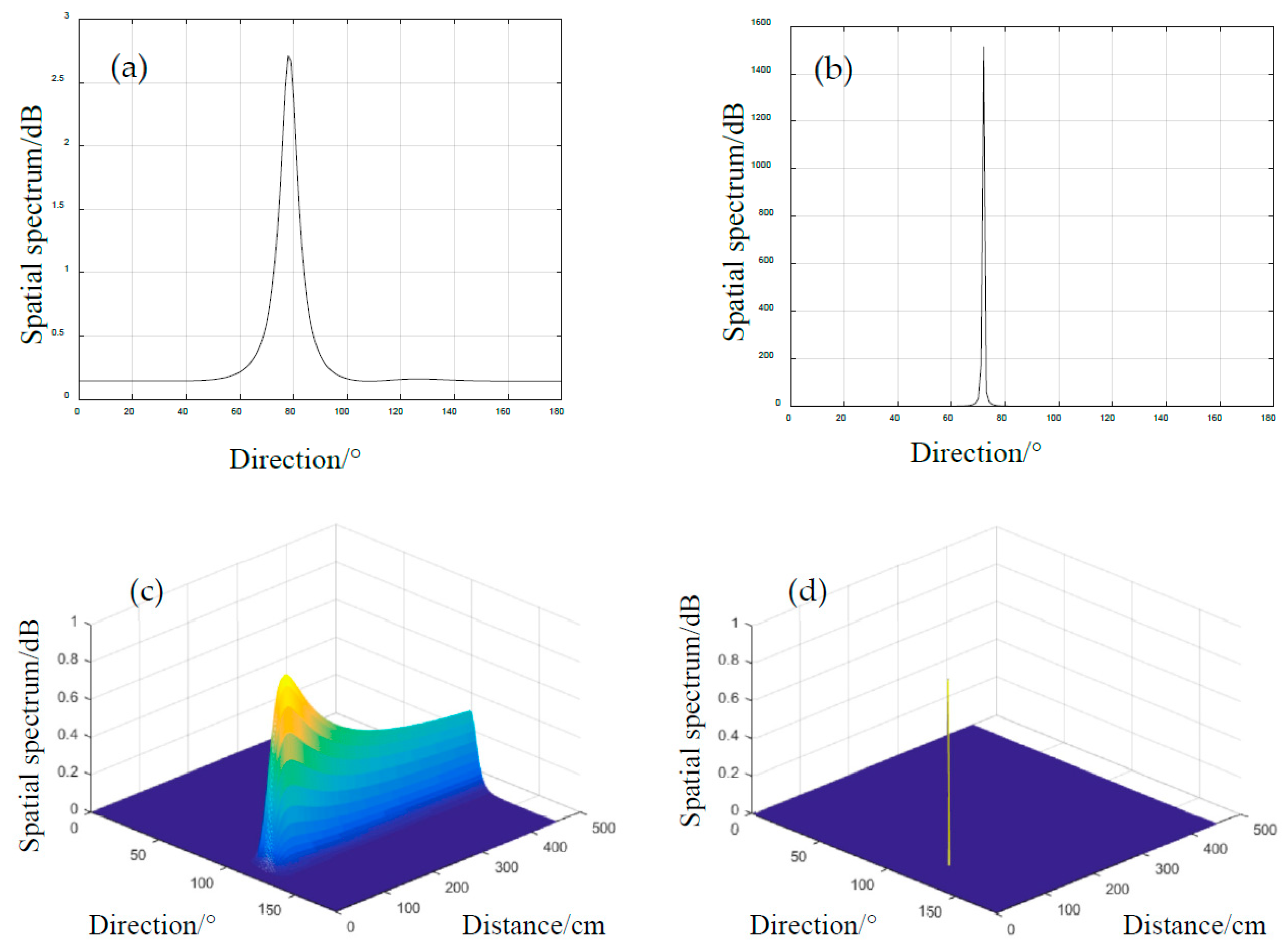
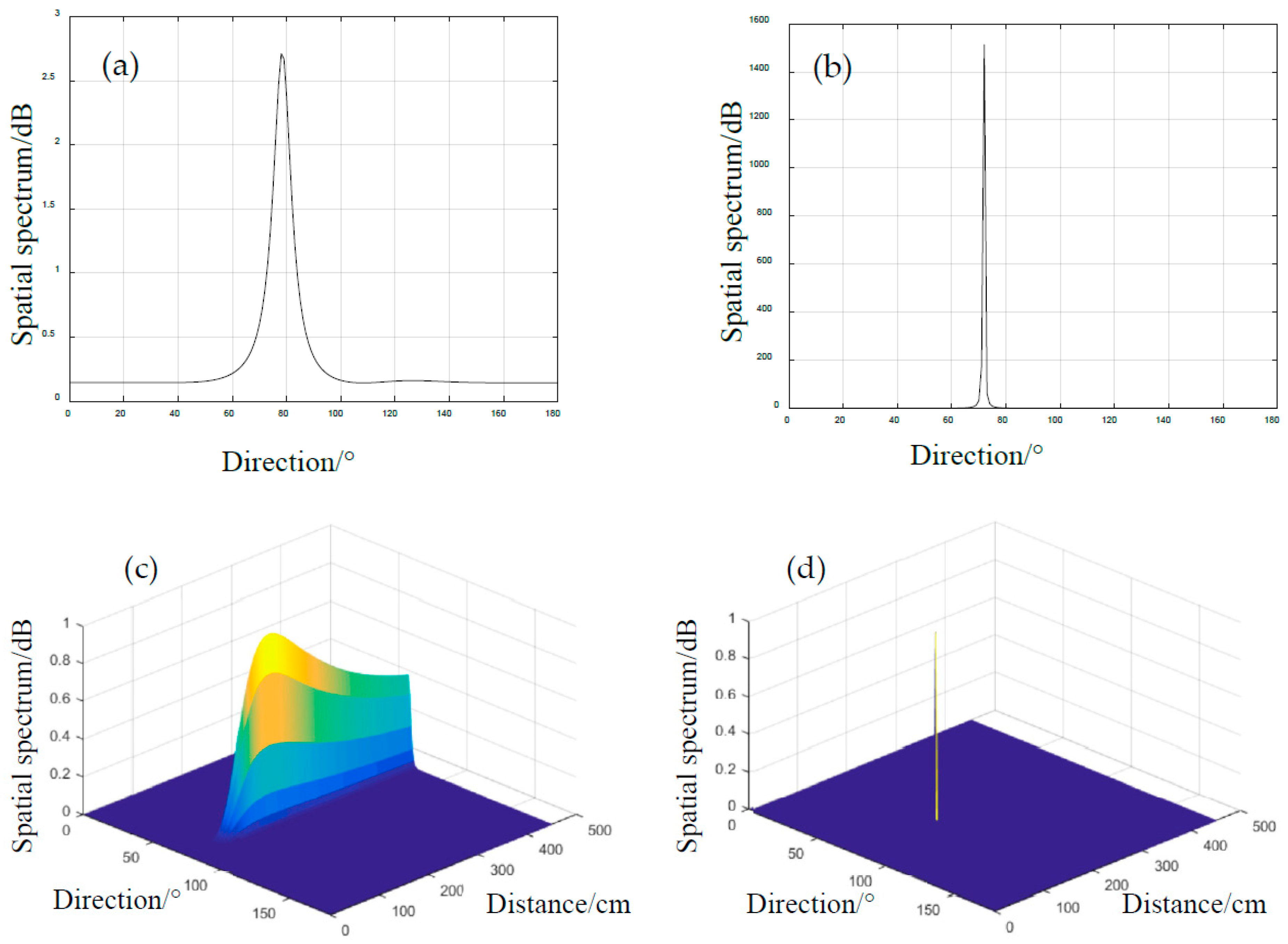
| Parameters | Case #1 | Case #2 | Case #3 | Case #4 |
|---|---|---|---|---|
| (mm) | 131 | 190 | 76 | 189 |
| (°) | 108 | 76 | 121 | 102 |
| Impact Case | Classical 1D-MUSIC | Standard 2D-MUSIC | Proposed Method | ||||
|---|---|---|---|---|---|---|---|
| /mm | /° | / | / | / | / | / | / |
| 131 | 108 | 105/3 | 108/0 | 114/17 | 104/4 | 114/17 | 106/2 |
| 189 | 102 | 98/4 | 105/3 | 176/13 | 100/2 | 176/13 | 102/0 |
| 76 | 121 | 112/9 | 116/5 | 72/4 | 117/4 | 72/4 | 119/2 |
| 190 | 76 | 74/2 | 76/0 | 167/22 | 75/1 | 167/22 | 76/0 |
© 2020 by the authors. Licensee MDPI, Basel, Switzerland. This article is an open access article distributed under the terms and conditions of the Creative Commons Attribution (CC BY) license (http://creativecommons.org/licenses/by/4.0/).
Share and Cite
Ren, L.; Zhong, Y.; Xiang, J.; Wang, Z. Adaptive Sensor Array Error Calibration Based Impact Localization on Composite Structure. Appl. Sci. 2020, 10, 4042. https://doi.org/10.3390/app10114042
Ren L, Zhong Y, Xiang J, Wang Z. Adaptive Sensor Array Error Calibration Based Impact Localization on Composite Structure. Applied Sciences. 2020; 10(11):4042. https://doi.org/10.3390/app10114042
Chicago/Turabian StyleRen, Li, Yongteng Zhong, Jiawei Xiang, and Zhiling Wang. 2020. "Adaptive Sensor Array Error Calibration Based Impact Localization on Composite Structure" Applied Sciences 10, no. 11: 4042. https://doi.org/10.3390/app10114042