
Novel Adaptive Magnetic Springs for Reliable Industrial Variable Stiffness Actuation

Abstract
:1. Introduction
- Improved energy efficiency;
- Improved actuator density or reduced actuator size and cost;
- Faster operation, i.e., increased production rate.
- Mechanical springs are not suitable for industrial applications, due to fatigue failure, see, e.g., [7].
- Magnetic spring are promising for industrial applications, see, e.g., [33]; they can significantly reduce the energy consumption and/or increase the production rate, with a virtually unlimited lifetime.
- Novel adaptive magnetic spring (AMS) concept and prototype.
- Model-based co-design toolchain for magnetic-spring-equipped systems, aiming to optimize system dynamics, controls and sizing/configuration of the magnetic springs. To do so, we build on the workflow as considered in [35] (DriveTrain Co-Design Toolchain), by employing Simscape [36], CasADi [37] and IPOPT [38].
- Magnetic spring component design tool, employing Matlab in tandem with FEMM [39].
- Demonstration of the added value of the AMS on an industrially relevant weaving loom use case, in a simulation and via experiments.
2. Proposed Innovative Concepts and Problem Definition
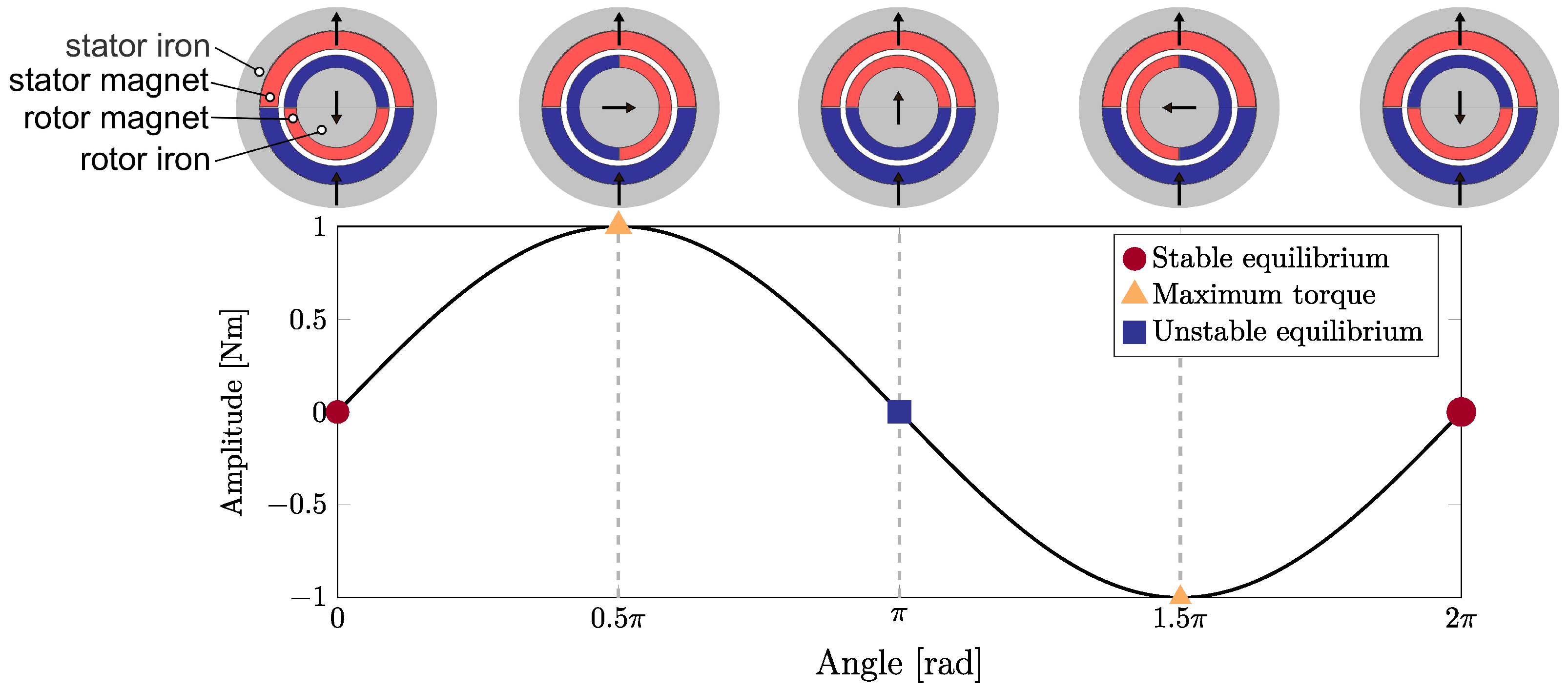
2.1. Passive Magnetic Spring Concepts
2.2. Adaptive Magnetic Spring Concepts
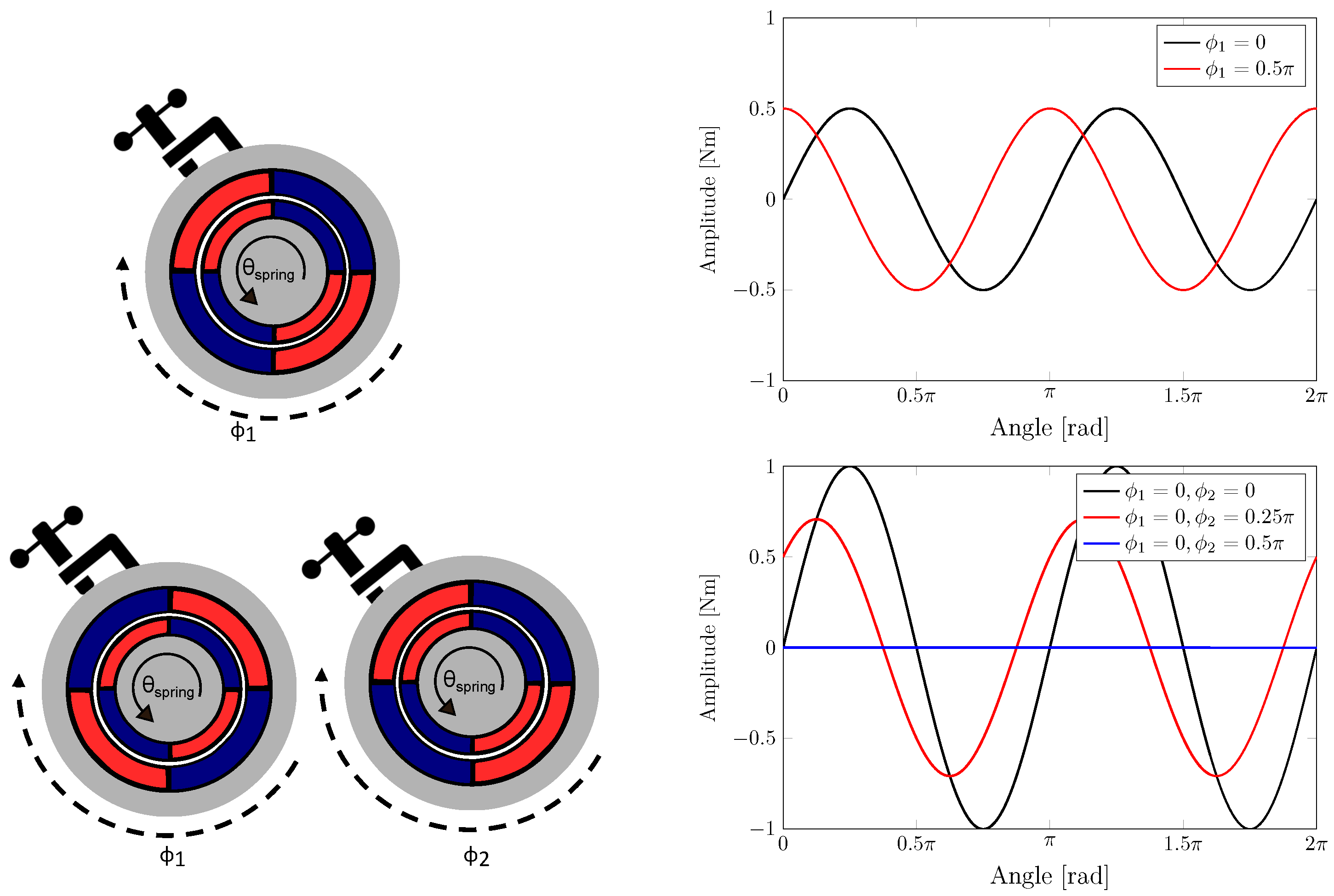
2.2.1. Novel Concept 1: Adaptive Phase
- Spring setting. The stator is unlocked, for which energy expenditure is required in the locking mechanism. The stator then follows the motion of the rotor due to the magnetic coupling between the stator and rotor. This allows for the primary mover, i.e., the servo motor used to control the process, to change the orientation of the stator without requiring a secondary high-performance mover.
- Machine operation. The stator is fixed with the locking mechanism (which from then on does not consume energy). Then, the desired machine motion can be executed with an optimal phase alignment of the magnetic spring.
2.2.2. Novel Concept 2: Adaptive Phase and Amplitude
2.3. Weaving Loom Drivetrain Use Case
- Nominal operation. When the machine is operating around a required average speed, motor torque ripple is encountered due to oscillating masses (e.g., shedding mechanisms) combined with the non-linearity of the mechanism.
- Start-stop behaviour. Typically, the goal is to start or stop the machine within a given amount of machine cycles, requiring a fast ramp-up or ramp-down of the speed (limited by peak motor torque). When failing to do so, woven products might have a lower quality due to the so-called “starting marks” from a too low speed at beat-up.
- Maximally allowed speed fluctuations during continuous operations, since these fluctuations affect the process quality, i.e., the quality of the woven fabric.
- Actuator torque limits (peak and RMS), due to thermal limitations of the servo motor depending on the cooling approach.
3. Model-Based Co-Design Toolchain for Magnetic-Spring Equipped Systems
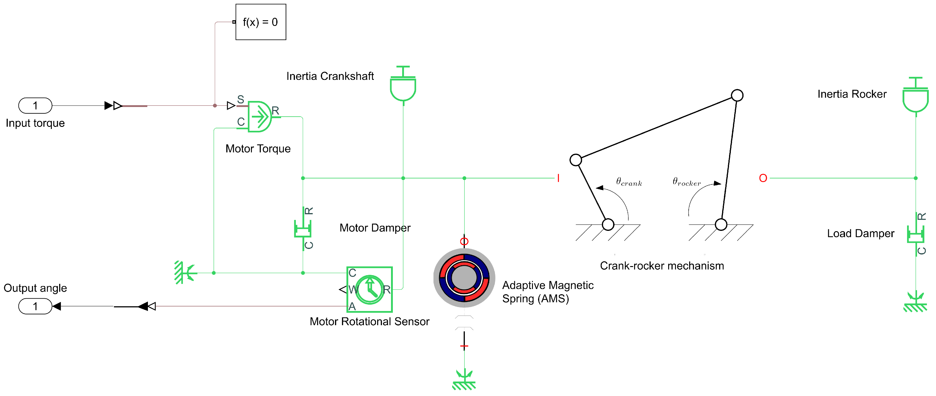
- Model generation (including the magnetic spring). The system is modelled in Simscape. Afterwards, symbolic model equations are extracted to white-box CasADi symbolics [37] using the tool Simscape2CasADi [41]. These symbolic equations enable efficient (high-order) derivative evaluation through algorithmic differentiation, and are used to facilitate optimization of the system design and controls in the next step.
- Optimal system and control design. Employing the model obtained in the previous step, the dynamics and controls of the system are optimized, along with the desired magnetic spring profile, sizing and configuration.
3.1. Model Generation
Magnetic Spring: Scaling Inertia Model
3.2. Optimal System and Control Design
3.2.1. Generic Discrete-Time Co-Design Problem Formulation
3.2.2. Fixed Sinusoidal Magnetic Springs
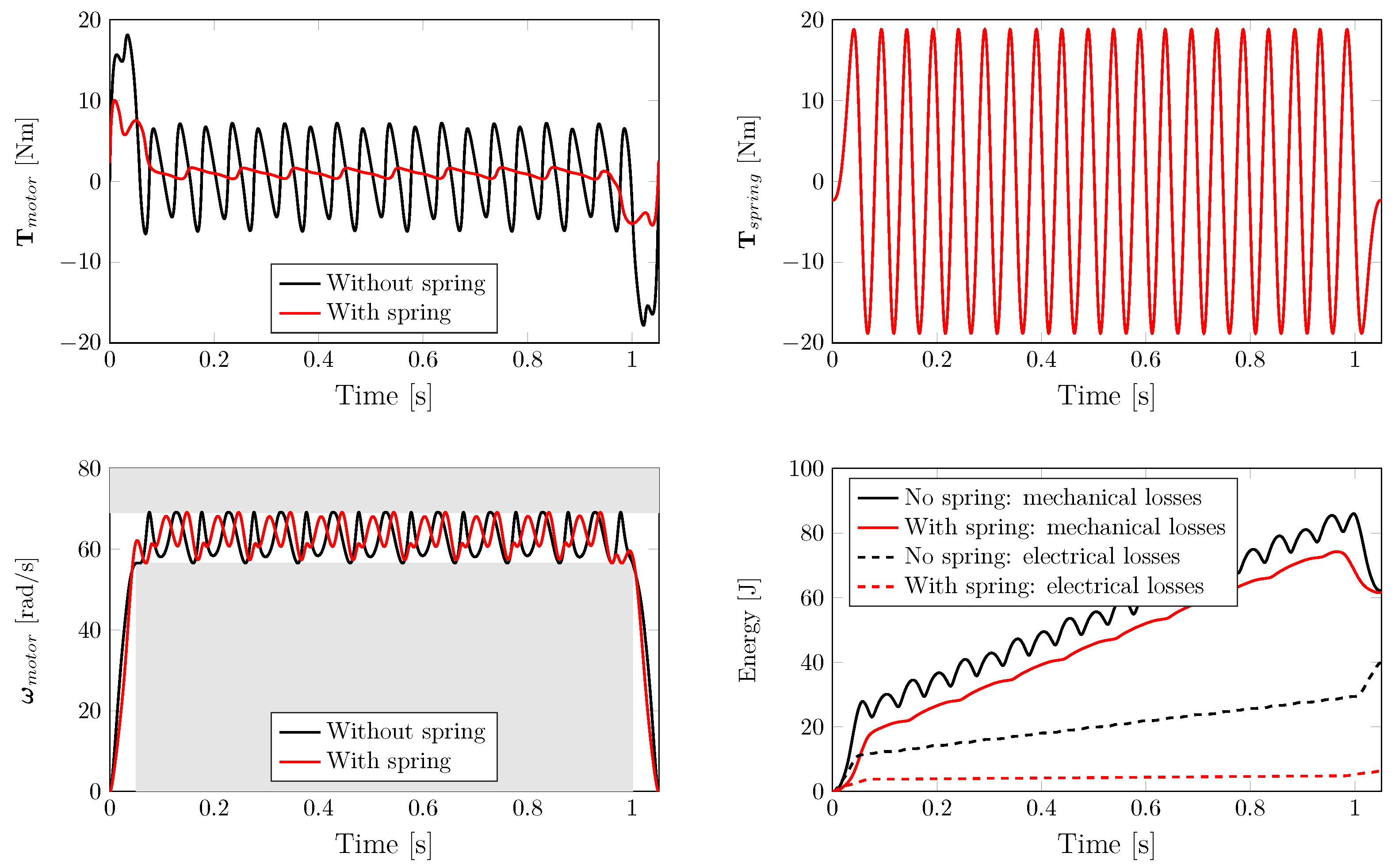
3.3. Simulation Example: Benefits of Fixed Sinusoidal Magnetic Springs
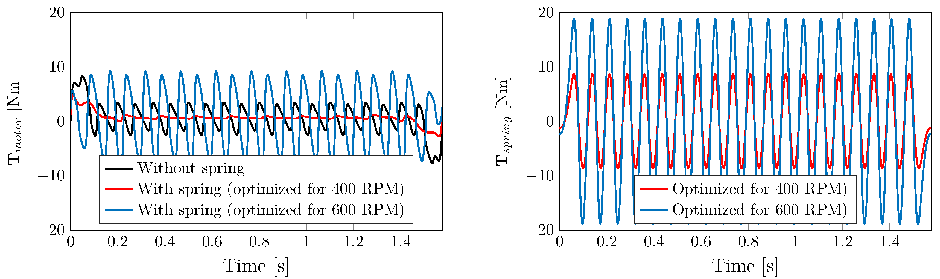
3.4. Simulation Counter-Example: Limitations of Fixed Sinusoidal Magnetic Springs
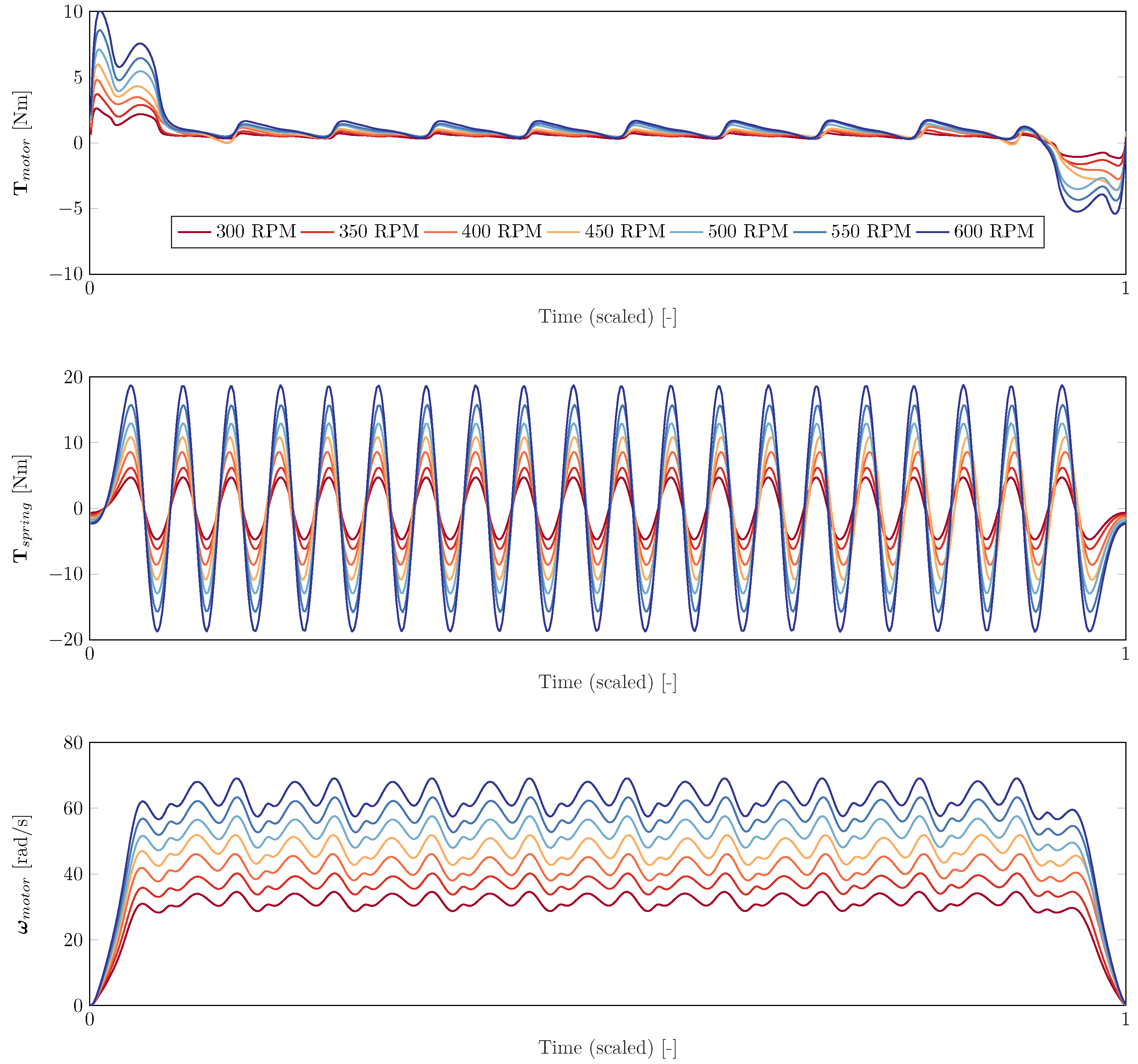
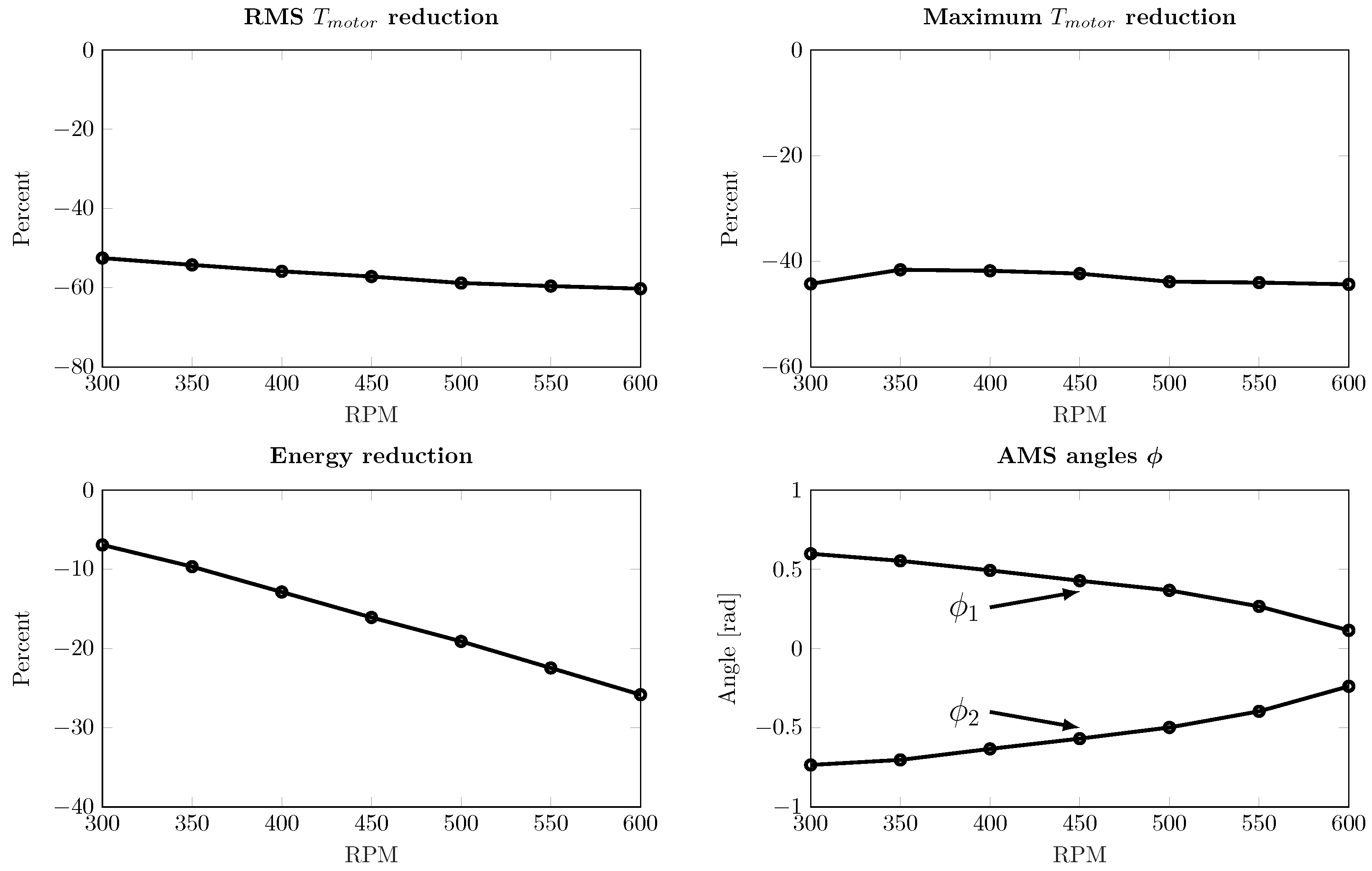
Novel Adaptive Magnetic Springs
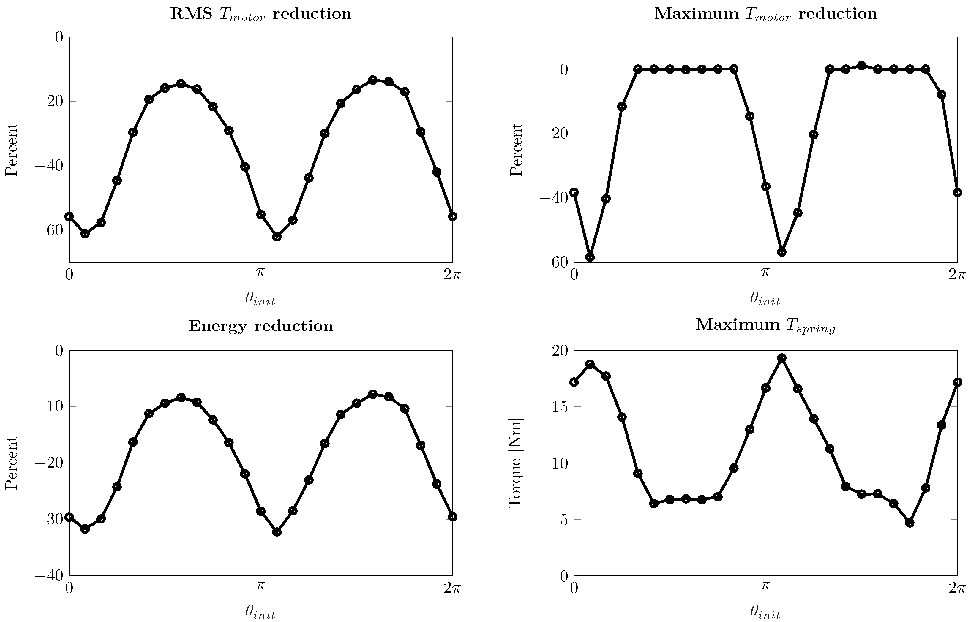
- The RMS motor torque is reduced by 13–62%. The energy consumption is reduced by 8–32%.
- The peak motor torque is in some cases kept constant (for both cases equal to the allowed maximum of ±20 Nm), whereas in some other cases the peak motor torques are reduced by up to 60%.
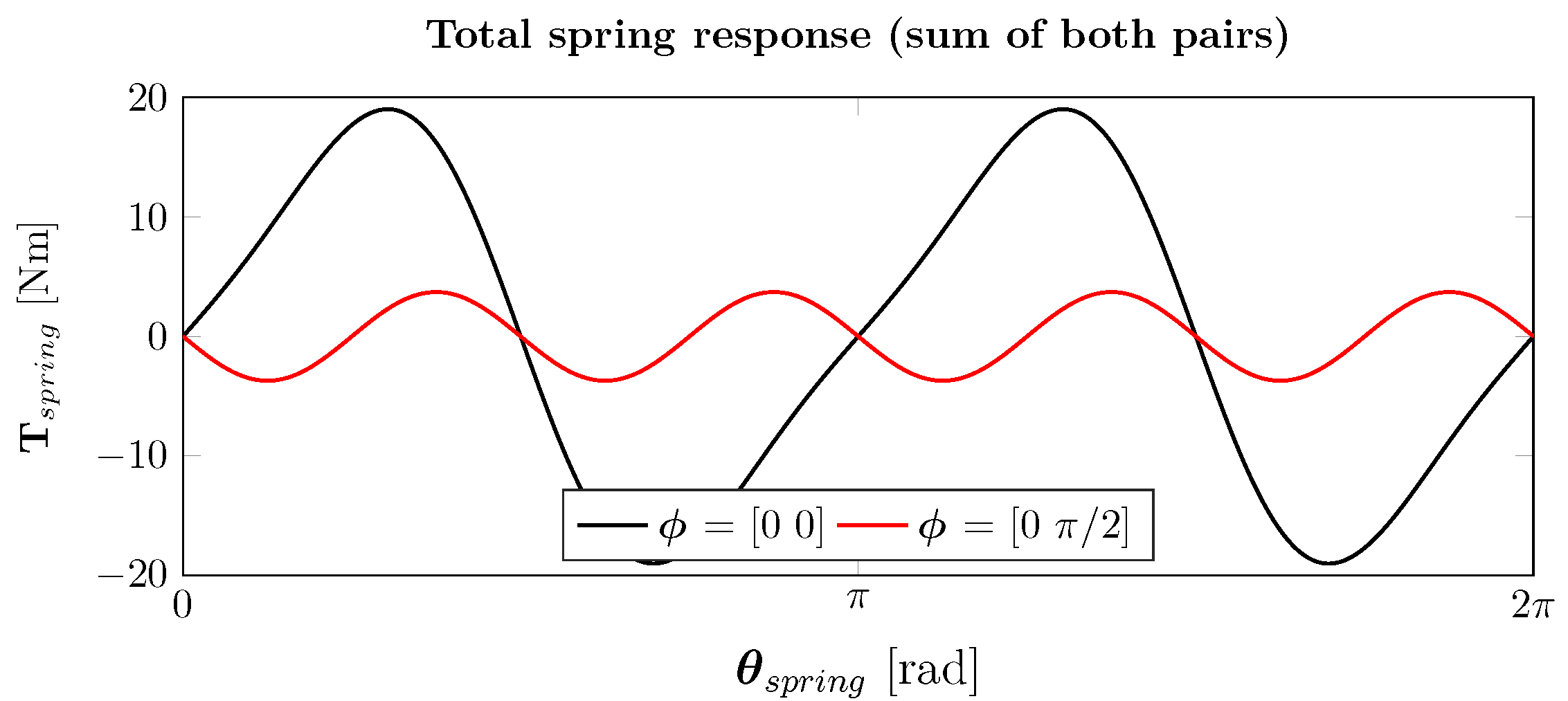
- The peak magnetic spring torque varies between approximately 5–20 Nm. When considering an amplitude Nm for each pair, the pairs are fully aligned for the case where the peak spring torque is 20 Nm, and close to anti-phase in the case of 5 Nm.


4. Novel Adaptive Magnetic Spring: Component Design
4.1. Optimal Component Design
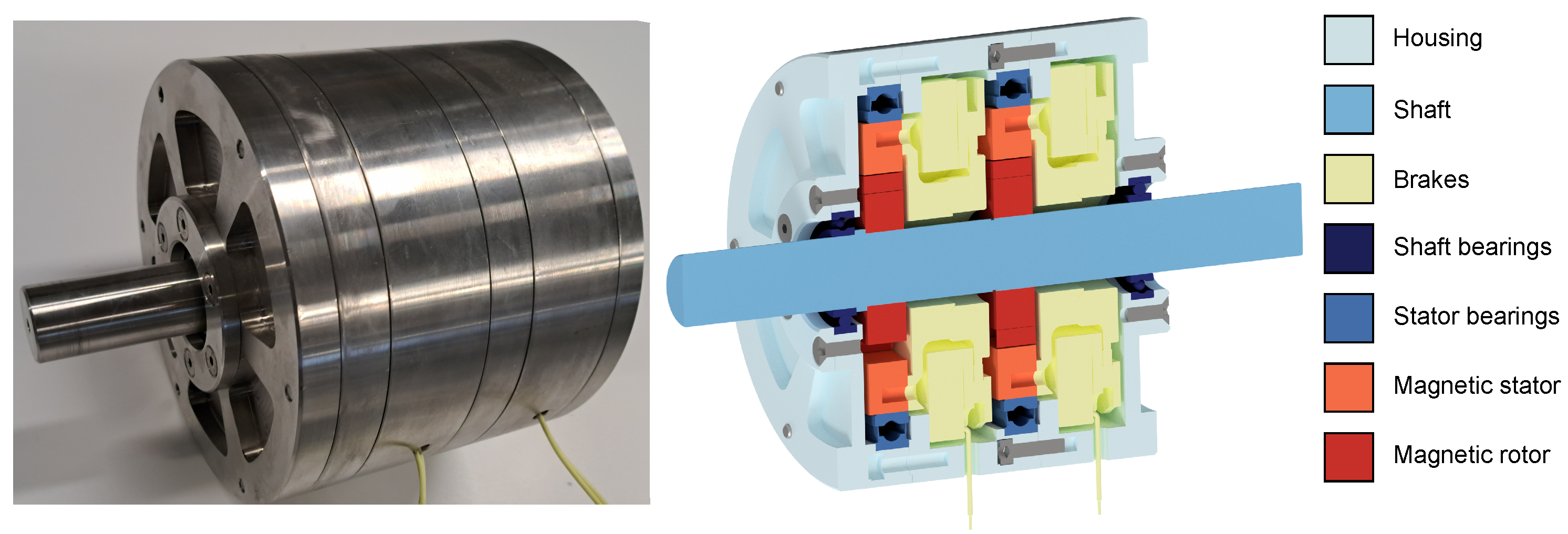
4.2. Prototype Adaptive Magnetic Spring
5. System Experimental Validation
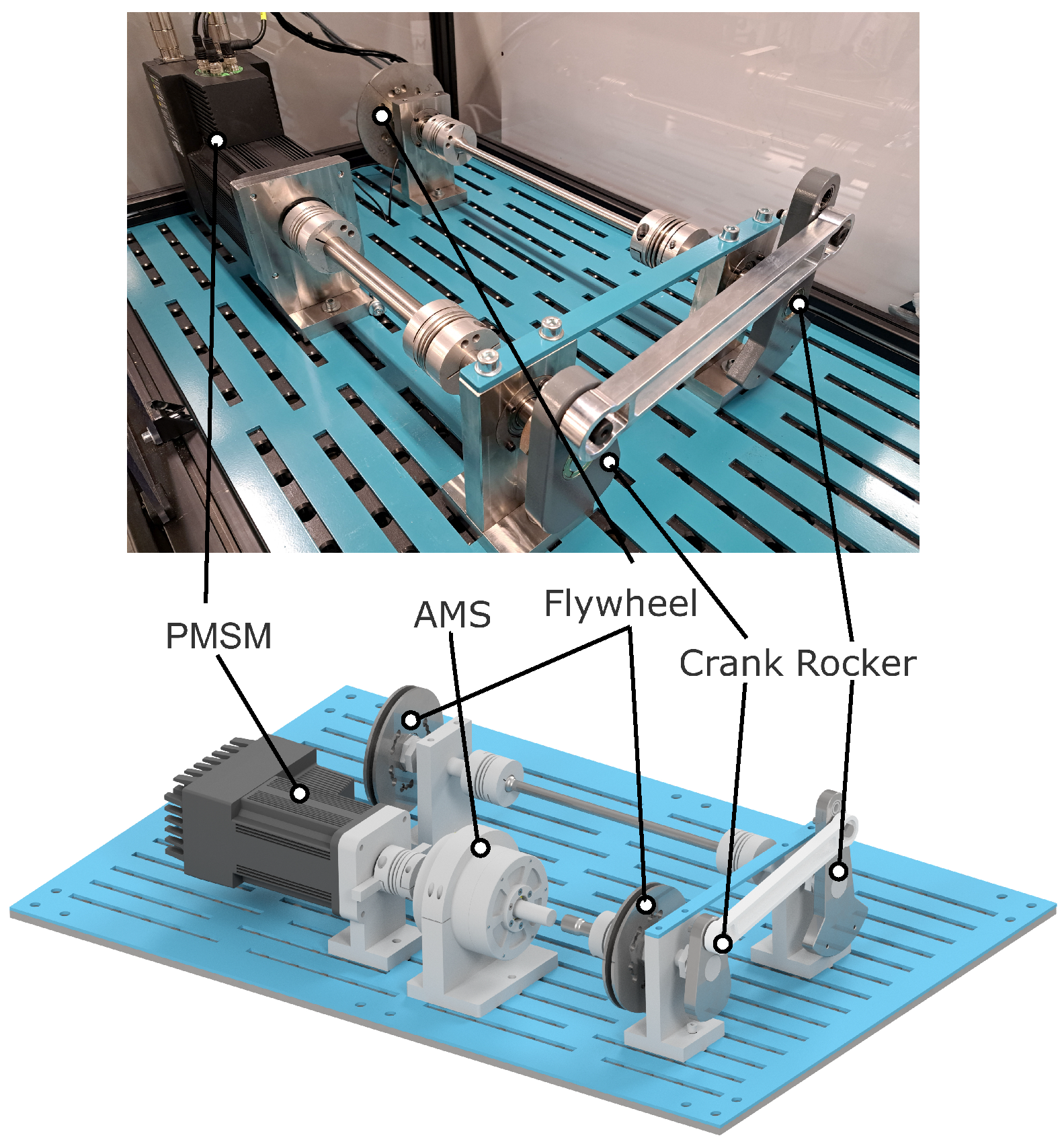
5.1. Experiment Description
5.2. Results
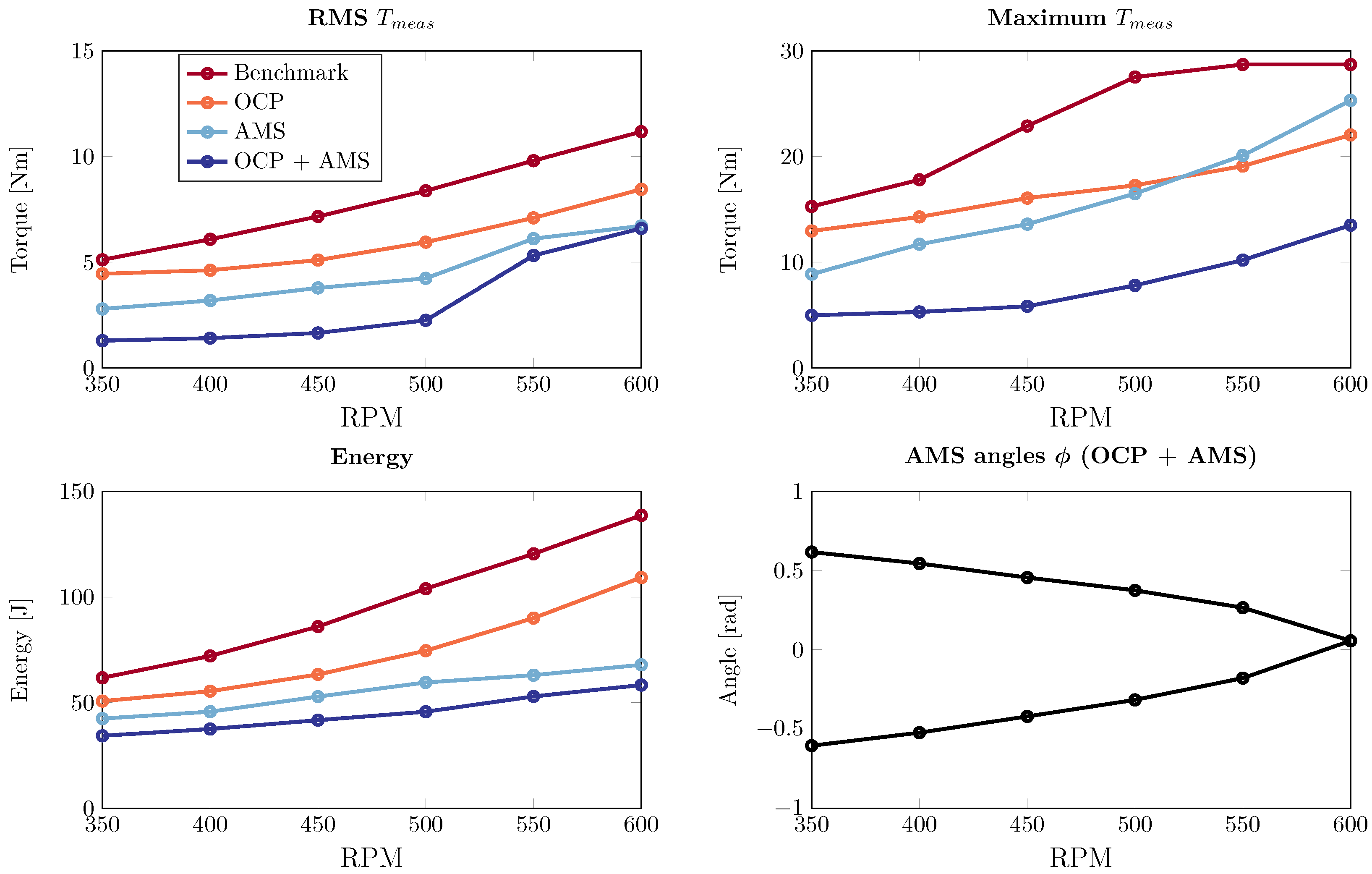
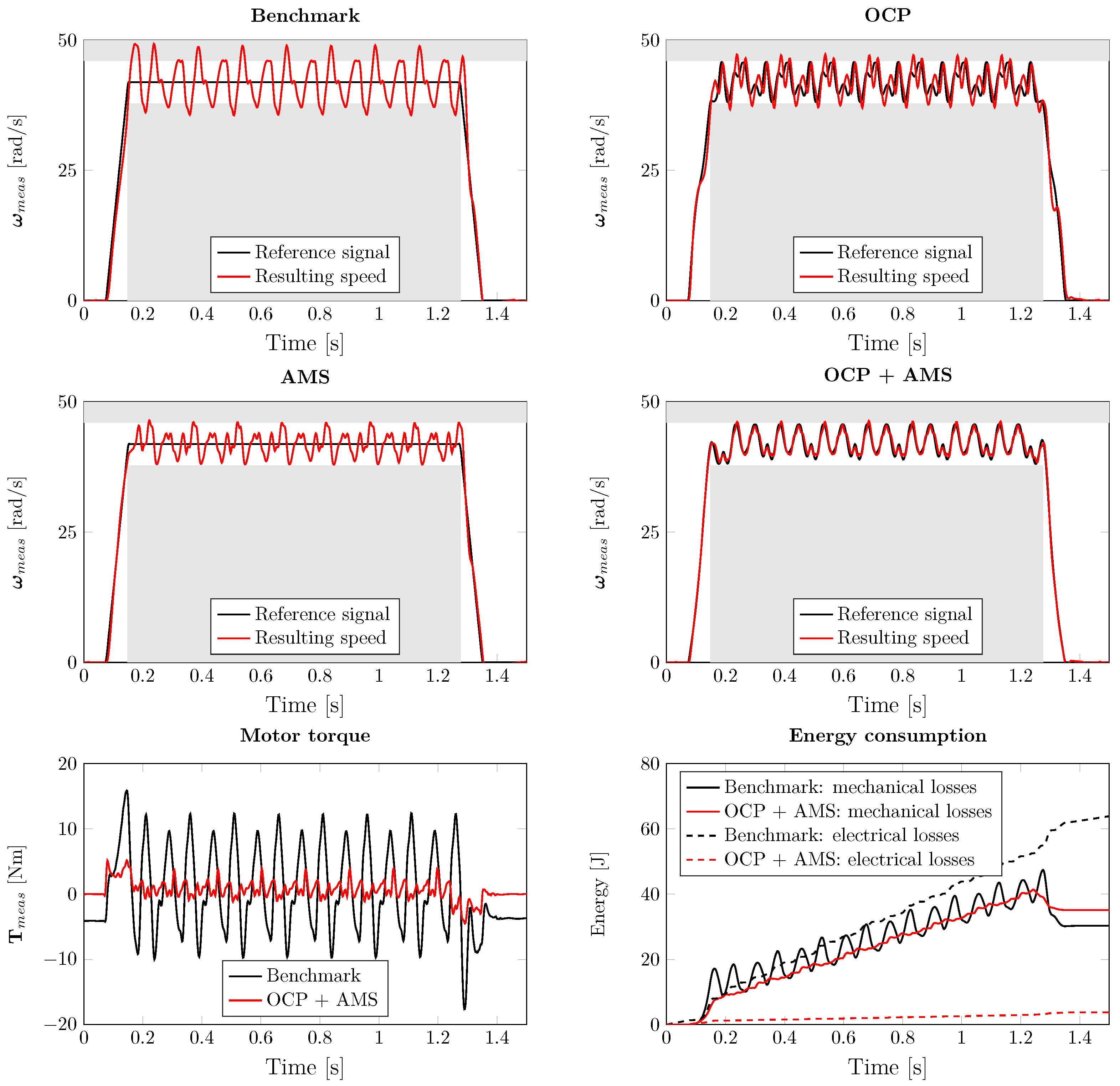
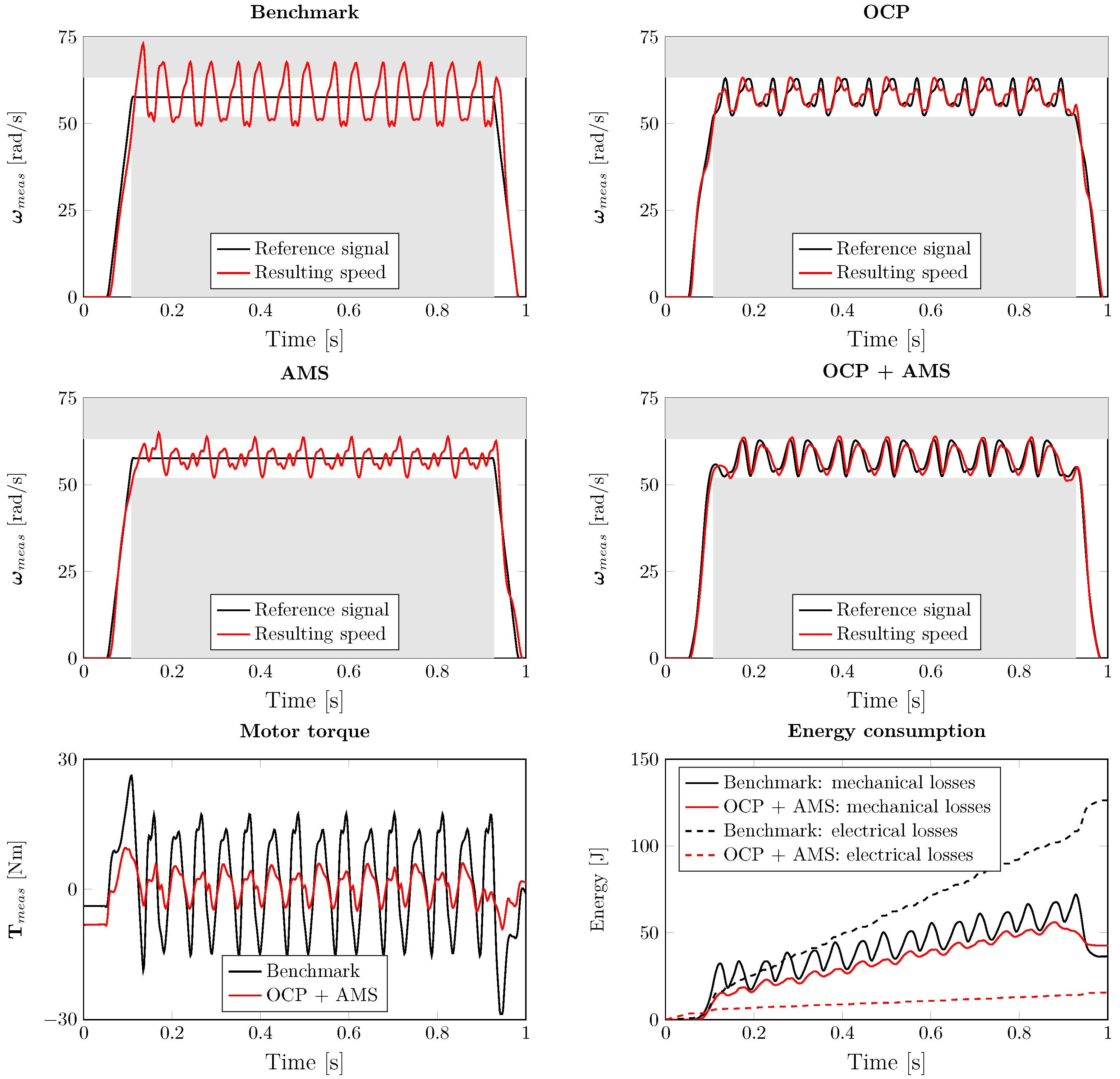
- It can be seen that the benchmark case demands high peak and RMS torques from the motor and consumes the most energy. For the higher operating speeds, the peak motor torque reaches a maximum of 28.7 Nm.
- When the controls are optimized and the feed-forward control signal is added (OCP), we can reduce the required motor torques and the energy consumption with respect to the benchmark.
- Optimizing the angles of the magnetic spring (AMS), while only using a PI controller, further reduces the required energy and RMS motor torque. For higher speeds, the required peak motor torque is higher than for the OCP case.
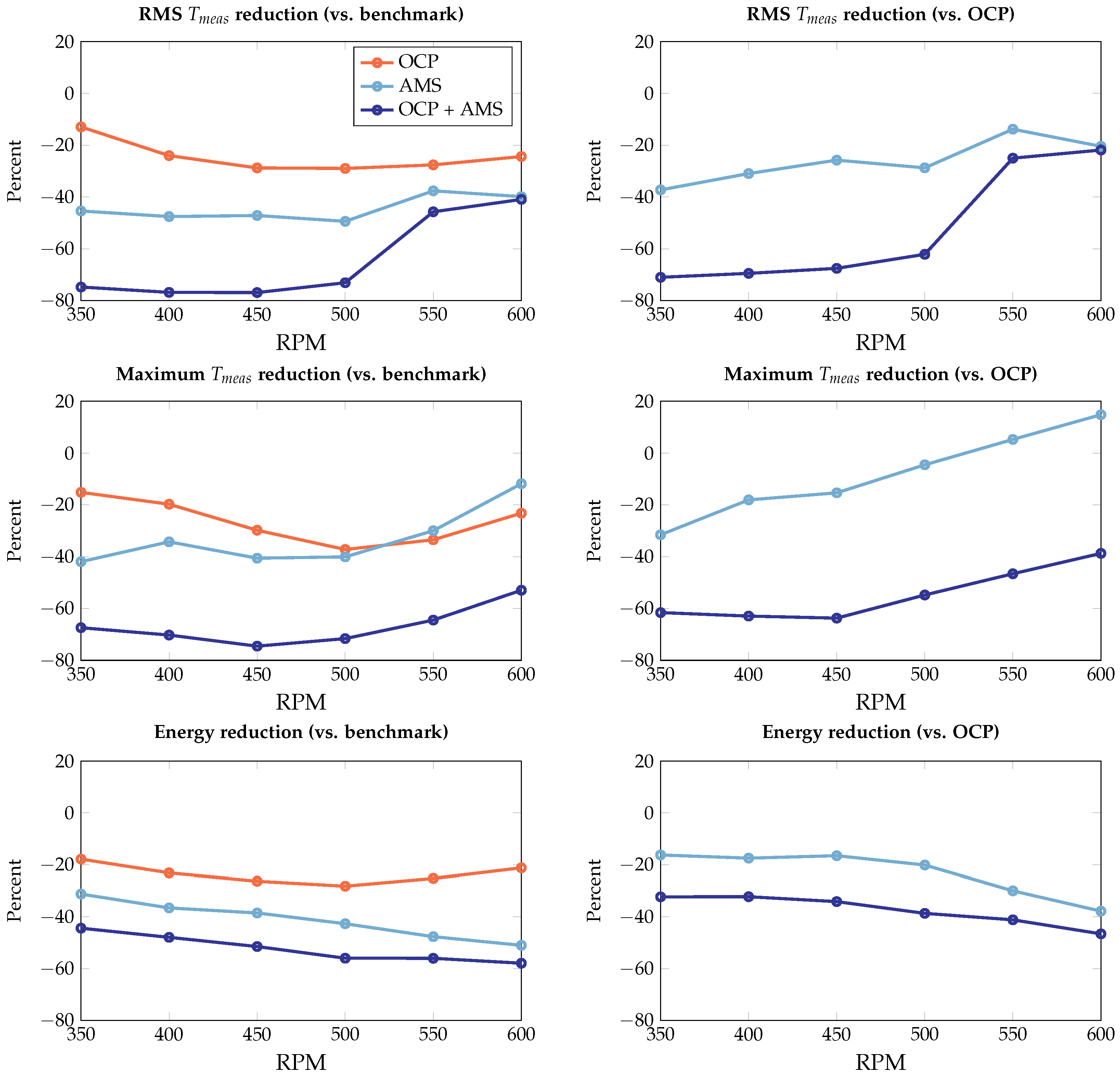
- When both the angles of the magnetic spring and the controls are optimized (OCP + AMS), the best performance is obtained. With respect to the benchmark, we reduce the RMS motor torque by 41–77% and the peak motor torque by 53–75%. The energy consumption is reduced by 44–58%. With respect to the OCP case, we obtain reductions of 22–71% (RMS motor torque), 39–64 % (peak motor torque) and 32–47% (energy consumption). Hence, due to the flexibility of the adaptive magnetic spring, combined with the optimized controls, significant reductions are achieved throughout the considered speed range.


5.3. Energy Consumption for Spring Pre-Setting
6. Conclusions and Outlook
- Other applications. Apart from weaving, the AMS could find its application in other above-mentioned highly dynamic and repetitive motions in machines (point-to-point machines, punching, stamping, printing, oscillating piston compressors, packaging etc.). On top of the mentioned one-degree-of-freedom systems, AMS could allow the use of PEA concepts in industrial robotics with multiple degrees of freedom, in particular in high-speed parallel pick-and-place robots (e.g., delta-bots, parallel SCARA robots), where the full actuator mass is concentrated at the base of the robot.
- Linear or rotational magnetic springs. Although the focus of this article is on rotational actuators, our findings, especially ones related to the underlying physics and design methodology, can be extended to linear motion systems. Nevertheless, it has previously been noted [21,49] that linear systems have higher losses due to the limitations of prismatic bearings, even though this conclusion might not hold on smaller scales, as suggested in a recent publication [50]. In future, a more systematic comparison of rotational and linear motion systems with magnetic spring-assisted actuators is expected.
- Iterative learning control. The model used to solve the optimal control problems contains slight mismatches with respect to the actual dynamics of the experimental setup. These mismatches result in imperfections in the obtained control signals and determined magnetic spring settings. In order to deal with this, iterative learning control (ILC) could be employed to iteratively reduce the model–plant mismatch, thereby further improving the control performance [51].
- General use of the co-design toolchain. The toolchain introduced in Section 3 is applicable to solving co-design / optimal control problems for various system types where dynamic model equations are available. These tools have so far been already applied to several domains, e.g., mechanical, thermal, electromagnetic and multi-physics, see e.g., [35].
Author Contributions
Funding
Institutional Review Board Statement
Informed Consent Statement
Data Availability Statement
Conflicts of Interest
References
- Spyrakos-Papastavridis, E.; Childs, P.R.N.; Dai, J.S. Passivity Preservation for Variable Impedance Control of Compliant Robots. IEEE/ASME Trans. Mechatron. 2020, 25, 2342–2353. [Google Scholar] [CrossRef]
- Wolf, S.; Grioli, G.; Eiberger, O.; Friedl, W.; Grebenstein, M.; Höppner, H.; Burdet, E.; Caldwell, D.G.; Carloni, R.; Catalano, M.G.; et al. Variable Stiffness Actuators: Review on Design and Components. IEEE/ASME Trans. Mechatron. 2016, 21, 2418–2430. [Google Scholar] [CrossRef]
- Plooij, M.; Wisse, M.; Vallery, H. Reducing the energy consumption of robots using the bidirectional clutched parallel elastic actuator. IEEE Trans. Robot. 2016, 32, 1512–1523. [Google Scholar] [CrossRef]
- Csencsics, E.; Schitter, G. Exploring the Pareto Fronts of Actuation Technologies for High Performance Mechatronic Systems. IEEE/ASME Trans. Mechatron. 2021, 26, 1053–1063. [Google Scholar] [CrossRef]
- Bertoldi, P.; Hirl, B.; Labanca, N. Energy Efficiency Status Report 2012; JRC Technical Reports; European Union: Luxembourg, 2012; p. 143. [Google Scholar] [CrossRef]
- Mrak, B.; Lenaerts, B.; Driesen, W.; Desmet, W. Optimal magnetic spring for compliant actuation-validated torque density benchmark. Actuators 2019, 8, 18. [Google Scholar] [CrossRef]
- Mrak, B.; Adduci, R.; Weckx, S.; Driesen, W.; Desmet, W. Novel phase-bound magnetic vibration absorber for improved NVH performance of a wind turbine gearbox. In Proceedings of the ISMA 2018—International Conference on Noise and Vibration Engineering, Leuven, Belgium, 17–19 September 2018; pp. 4833–4845. [Google Scholar]
- Patt, P.J. Design and Testing of a Coaxial Linear Magnetic Spring with Integral Linear Motor. IEEE Trans. Magn. 1985, MAG-21, 1759–1761. [Google Scholar] [CrossRef]
- Boisclair, J.; Richard, P.L.; Laliberté, T.; Gosselin, C. Gravity Compensation of Robotic Manipulators Using Cylindrical Halbach Arrays. IEEE/ASME Trans. Mechatron. 2017, 22, 457–464. [Google Scholar] [CrossRef]
- Janssen, J.L.G.; Paulides, J.J.H.; Lomonova, E.A.; Delinchant, B.; Yonnet, J.P. Design study on a magnetic gravity compensator with unequal magnet arrays. Mechatronics 2013, 23, 197–203. [Google Scholar] [CrossRef]
- King, C.; Beaman, J.J.; Sreenivasan, S.V.; Campbell, M. Multistable Equilibrium System Design Methodology and Demonstration. J. Mech. Des. 2004, 126, 1036. [Google Scholar] [CrossRef]
- Janssen, J.L.G.; Paulides, J.J.H.; Lomonova, E.A. Study of Magnetic Gravity Compensator Topologies Using an Abstraction in the Analytical Interaction Equations. Prog. Electromagn. Res. 2012, 128, 75–90. [Google Scholar] [CrossRef]
- Robertson, W.; Cazzolato, B.; Zander, A. A multipole array magnetic spring. IEEE Trans. Magn. 2005, 41, 3826–3828. [Google Scholar] [CrossRef]
- LinMot Inc. Data Book 0185-0124 (EN): LinMot Data Book, 24th ed.; Technical Report; LinMot: Spreitenbach, Switzerland.
- Mizuno, T.; Takasaki, M.; Kishita, D.; Hirakawa, K. Vibration isolation system combining zero-power magnetic suspension with springs. Control. Eng. Pract. 2007, 15, 187–196. [Google Scholar] [CrossRef]
- Li, Q.; Zhu, Y.; Xu, D.; Hu, J.; Min, W.; Pang, L. A negative stiffness vibration isolator using magnetic spring combined with rubber membrane. J. Mech. Sci. Technol. 2013, 27, 813–824. [Google Scholar] [CrossRef]
- Snamina, J.; Habel, P. Magnetic spring as the element of vibration reduction system. Mech. Control. 2010, 29, 40–44. [Google Scholar]
- Zhong, J.; Cheng, Z.; Ge, Z.; Zhang, Y.; Lu, W.; Song, F.; Li, C. Nonlinear vibration of a magnetic spring. Phys. Educ. 2012, 47, 444. [Google Scholar] [CrossRef]
- Foisal, A.R.M.; Hong, C.; Chung, G.S. Multi-frequency electromagnetic energy harvester using a magnetic spring cantilever. Sens. Act. Phys. 2012, 182, 106–113. [Google Scholar] [CrossRef]
- Poltschak, F. A high efficient linear motor for compressor applications. In Proceedings of the Power Electronics, Electrical Drives, Automation and Motion (SPEEDAM), 2014 International Symposium, Ischia, Italy, 18–20 June 2014; pp. 1356–1361. [Google Scholar] [CrossRef]
- Poltschak, F.; Ebetshuber, P. Design of Integrated Magnetic Springs for Linear Oscillatory Actuators. IEEE Trans. Ind. Appl. 2018, 54, 2185–2192. [Google Scholar] [CrossRef]
- Boldea, I.; Congxiao, W.; Bin, Y.; Nasar, S.A. Analysis and design of flux-reversal linear permanent magnet oscillating machine. In Proceedings of the Industry Applications Conference Thirty-Third IAS Annual Meeting, St. Louis, MO, USA, 12–15 October 1998; Volume 1, pp. 136–143. [Google Scholar] [CrossRef]
- Paden, B.A.; Fiske, O.J.; Ricci, M.R.; Okcuoglu, M.; Paden, D.B.; Paden, B.E. Electromagnetic Valve Apparatus with Nonlinear Spring. U.S. Patent No 9,395,012, 19 July 2016. [Google Scholar]
- Paden, B.E.; Chen, C.; Fiske, J.F. Magnetic Spring and Actuators with Multiple Equilibrium Positions. U.S. Patent US7265470B1, 4 September 2007. [Google Scholar]
- Sudano, A.; Tagliamonte, N.L.; Accoto, D.; Guglielmelli, E. A resonant parallel elastic actuator for biorobotic applications. In Proceedings of the IEEE International Conference on Intelligent Robots and Systems, Chicago, IL, USA, 14–18 September 2014; pp. 2815–2820. [Google Scholar] [CrossRef]
- Sudano, A.; Accoto, D.; Zollo, L.; Guglielmelli, E. Design, development and scaling analysis of a variable stiffness magnetic torsion spring. Int. J. Adv. Robot. Syst. 2013, 10, 372. [Google Scholar] [CrossRef]
- Verstraten, T.; López-García, P.; Lenaerts, B.; Mrak, B.; Lefeber, D.; Vanderborght, B. Improving the performance of industrial machines with variable stiffness springs. Mech. Based Des. Struct. Mach. 2022, 50, 115–134. [Google Scholar] [CrossRef]
- Che, D.; Bird, J.Z.; Hagmüller, A.; Hossain, M.E. An Adjustable Stiffness Torsional Magnetic Spring with a Linear Stroke Length. In Proceedings of the 2021 IEEE Energy Conversion Congress and Exposition (ECCE), Vancouver, BC, Canada, 10–14 October 2021; pp. 5944–5948. [Google Scholar] [CrossRef]
- Ibrahim, M.; Sergeant, P. Dynamic Modelling and Analysis of Electric Motor with Integrated Magnetic Spring Driving Weaving Loom Application. IEEE Trans. Ind. Electron. 2022, 70, 2329–2338. [Google Scholar] [CrossRef]
- Woodward, M.A.; Sitti, M. Tailored Magnetic Springs for Shape-Memory Alloy Actuated Mechanisms in Miniature Robots. IEEE Trans. Robot. 2019, 35, 589–601. [Google Scholar] [CrossRef]
- Woodward, M.A.; Sitti, M. Universal Custom Complex Magnetic Spring Design Methodology. IEEE Trans. Magn. 2018, 54, 8200213. [Google Scholar] [CrossRef]
- Mrak, B.; Wex, B.; Mitterhofer, H. Methodology for Shape Optimization of Magnetic Designs: Magnetic Spring Characteristic Tailored to Application Needs. Actuators 2022, 11, 37. [Google Scholar] [CrossRef]
- Coemelck, D.; Delboo, E.; Roelstraete, K. Driving Device for a Weaving Machine with a Supporting Device. BE Patent BE1026177A1, 28 October 2019. [Google Scholar]
- Mrak, B.; Lenaerts, B.; Jeurgen, M.; Driesen, W. Magnetic Spring. NL Patent NL2020783B1, 24 October 2019. [Google Scholar]
- Adduci, R.; Willems, J.; Kikken, E.; Gillis, J.; Croes, J.; Desmet, W. An Integrated Co-Design Optimization Toolchain Applied to a Conjugate Cam-Follower Drivetrain System. Machines 2023, 11, 486. [Google Scholar] [CrossRef]
- Hassell, T.J.; Weaver, W.W.; Oliveira, A.M. Using Matlab’s Simscape modeling environment as a simulation tool in power electronics and electrical machines courses. In Proceedings of the 2013 IEEE Frontiers in Education Conference (FIE), Oklahoma City, OK, USA, 23–26 October 2013; pp. 477–483. [Google Scholar]
- Andersson, J.A.E.; Gillis, J.; Horn, G.; Rawlings, J.B.; Diehl, M. CasADi—A software framework for nonlinear optimization and optimal control. Math. Program. Comput. 2019, 11, 1–36. [Google Scholar] [CrossRef]
- Wächter, A.; Biegler, L.T. On the implementation of an interior-point filter line-search algorithm for large-scale nonlinear programming. Math. Program. 2006, 106, 25–57. [Google Scholar] [CrossRef]
- Meeker, D. Finite element method magnetics. FEMM 2010, 4, 162. [Google Scholar]
- Kamadan, A.; Kiziltas, G.; Patoglu, V. Co-design strategies for optimal variable stiffness actuation. IEEE/ASME Trans. Mechatron. 2017, 22, 2768–2779. [Google Scholar] [CrossRef]
- Gillis, J.; Kikken, E. Symbolic Equation Extraction from SimScape. In Proceedings of the Benelux Meeting on Systems and Control, Soesterberg, The Netherlands, 27–29 March 2018. [Google Scholar]
- van de Wijdeven, J.; Bosgra, O.H. Using basis functions in iterative learning control: Analysis and design theory. Int. J. Control. 2010, 83, 661–675. [Google Scholar] [CrossRef]
- Camacho, E.F.; Alba, C.B. Model Predictive Control; Springer Science & Business Media: Singapore, 2013. [Google Scholar]
- Bock, H.; Plitt, K. A Multiple Shooting Algorithm for Direct Solution of Optimal Control Problems. IFAC Proc. Vol. 1984, 17, 1603–1608. [Google Scholar] [CrossRef]
- Rayner, R.M.; Sahinkaya, M.N.; Hicks, B. Improving the design of high speed mechanisms through multi-level kinematic synthesis, dynamic optimization and velocity profiling. Mech. Mach. Theory 2017, 118, 100–114. [Google Scholar] [CrossRef]
- Ouyang, T.; Wang, P.; Huang, H.; Zhang, N.; Chen, N. Mathematical modeling and optimization of cam mechanism in delivery system of an offset press. Mech. Mach. Theory 2017, 110, 100–114. [Google Scholar] [CrossRef]
- Vikse, M.; Watson, H.A.; Kim, D.; Barton, P.I.; Gundersen, T. Optimization of a dual mixed refrigerant process using a nonsmooth approach. Energy 2020, 196, 116999. [Google Scholar] [CrossRef]
- Audet, C.; Le Digabel, S.; Tribes, C. NOMAD User Guide; Technical Report G-2009-37; Les Cahiers du GERAD: Montreal, QC, Canada, 2009. [Google Scholar]
- Mrak, B.; Driesen, W.; Desmet, W. Magnetic Springs—Fast Energy Storage for Reciprocating Industrial Drivetrains. In Proceedings of the ABCM International Congress of Mechanical Engineering, Rio de Janeiro, Brazil, 6–11 December 2015; Volume 23. [Google Scholar]
- Bhushan, B.M.; Yoon, J.Y.; Griffith, L.G.; Trumper, D.L. Flux-Biased, Energy-Efficient Electromagnetic Micropumps Utilizing Bistable Magnetic Latching and Energy-Storage Springs. IEEE/ASME Trans. Mechatron. 2021, 26, 2362–2372. [Google Scholar] [CrossRef]
- Steinhauser, A.; Swevers, J. An Efficient Iterative Learning Approach to Time-Optimal Path Tracking for Industrial Robots. IEEE Trans. Ind. Inform. 2018, 14, 5200–5207. [Google Scholar] [CrossRef]


| Description | Value | Unit |
|---|---|---|
| PMSM peak torque | 28.7 | Nm |
| PMSM nominal torque | 9.55 | Nm |
| PMSM torque constant | 1.19 | Nm/A |
| PMSM resistance | 0.94 | |
| Crank arm length | 0.05 | m |
| Rocker arm length | 0.09 | m |
| Base length | 0.3 | m |
| Connecting rod length | 0.3 | m |
| PMSM inertia | 2.78 × 10 | kg/m |
| AMS (rotor) inertia | 5.18 × 10 | kg/m |
| Crank inertia | 5.86 × 10 | kg/m |
| Load inertia | 2.17 × 10 | kg/m |
| Crank-side viscous friction | 0.009 | Ns/m |
| Load-side viscous friction | 0.02 | Ns/m |
| Differential States | Unit | Symbol |
|---|---|---|
| Motor angle | rad | |
| Motor rotational speed | rad/s | |
| Rocker rotational speed | rad/s | |
| Linkage input angle | rad | |
| Linkage output angle | rad | |
| Magnetic spring angle | rad | |
| Algebraic States | Unit | Symbol |
| Linkage input torque | Nm | |
| Rocker torque | Nm | |
| Spring torque | Nm | |
| Inputs | Unit | Symbol |
| Motor torque | Nm | |
| Outputs | Unit | Symbol |
| Motor angle | rad | |
| Motor rotational speed | rad/s | |
| Linkage input angle | rad |
| Without Spring | With Spring | Reduction | |
|---|---|---|---|
| RMS | 6.15 Nm | 2.45 Nm | 60% |
| Max. | 18.15 Nm | 10.05 Nm | 45% |
| Energy | 88.65 J | 65.76 J | 26% |
| Considered Parameter | Corresponding Size |
|---|---|
| No. of magnets - | No. of magnets rotor and stator - and |
| pole pitch rotor | x pole pitch rotor |
| pole pitch stator | x pole pitch stator |
| magnet thickness rotor | x magnet thickness rotor |
| magnet thickness stator | x magnet thickness rotor |
| Feedback Controller (PI) | Feed-forward | Optimized Reference Signal | Optimized AMS Angles | |
|---|---|---|---|---|
| 1. Benchmark | × | |||
| 2. OCP | × | × | × | |
| 3. AMS | × | × | ||
| 4. OCP + AMS | × | × | × | × |
Disclaimer/Publisher’s Note: The statements, opinions and data contained in all publications are solely those of the individual author(s) and contributor(s) and not of MDPI and/or the editor(s). MDPI and/or the editor(s) disclaim responsibility for any injury to people or property resulting from any ideas, methods, instructions or products referred to in the content. |
© 2023 by the authors. Licensee MDPI, Basel, Switzerland. This article is an open access article distributed under the terms and conditions of the Creative Commons Attribution (CC BY) license (https://creativecommons.org/licenses/by/4.0/).
Share and Cite
Mrak, B.; Willems, J.; Baake, J.; Ganseman, C. Novel Adaptive Magnetic Springs for Reliable Industrial Variable Stiffness Actuation. Actuators 2023, 12, 191. https://doi.org/10.3390/act12050191
Mrak B, Willems J, Baake J, Ganseman C. Novel Adaptive Magnetic Springs for Reliable Industrial Variable Stiffness Actuation. Actuators. 2023; 12(5):191. https://doi.org/10.3390/act12050191
Chicago/Turabian StyleMrak, Branimir, Jeroen Willems, Jonathan Baake, and Chris Ganseman. 2023. "Novel Adaptive Magnetic Springs for Reliable Industrial Variable Stiffness Actuation" Actuators 12, no. 5: 191. https://doi.org/10.3390/act12050191