Article

A Comparative Study of Two Common Pump-Controlled Hydraulic Circuits for Single-Rod Actuators

1
Egyptian Government, Cairo 43200, Egypt
2
Department of Aerospace Engineering, Cairo University, Giza 12613, Egypt
3
Department of Mechanical Engineering, University of Manitoba, Winnipeg, MB R3T 2N2, Canada
*
Author to whom correspondence should be addressed.
Actuators 2023, 12(5), 193; https://doi.org/10.3390/act12050193
Submission received: 25 March 2023 / Revised: 21 April 2023 / Accepted: 26 April 2023 / Published: 3 May 2023
(This article belongs to the Special Issue Actuators in 2022)

Abstract

:
Pump-controlled hydraulic circuits are proven to be more efficient than conventional valve-controlled circuits. Pump-controlled hydraulic circuits for double rod cylinders are well developed and are in use in many practical applications. Existing pump-controlled circuits for single-rod actuators experience oscillation issues under specific operating conditions; that is identified as a critical operating zone on the load-velocity plane. The challenge in these circuits is to find out the proper way to compensate for the differential flow at both sides of the cylinder in all operating conditions. The two main types of valves commonly used by researchers, to compensate for differential flow in single-rod cylinder circuits, are: pilot-operated check valves, and shuttle valves. In this research, a performance comparison between circuits equipped with either valves, in terms of the size of the critical zone and the oscillations’ characteristics, was accomplished. Simulation studies showed that the circuits that utilize pilot-operated check valves possesses smaller oscillatory zones and less severe oscillations, when compared to circuits with shuttle valves. Experimental work verified the simulation results and proved the accuracy of the mathematical models. Hence, pump-controlled circuits with pilot-operated check valves are recommended to be the basic platform for further efforts to solve the oscillation problem in pump-controlled circuits.

1. Introduction

Conventional valve-controlled hydraulic circuits are favored in many applications, due to their fast response, high stiffness, high power to weight ratio, and stability under variable operating conditions. Low efficiency is the main disadvantage of these systems. Total efficiency of such systems is around 20% to 30% [1,2]. The efficiency of an industrial machine is critical, due to rising energy costs and environmental concerns. One significant solution to improve the efficiency of hydraulic circuits is to design a system with no metering valves [3]. These systems are controlled through the pump and are recognized as pump-controlled or throttle-less hydraulic circuits [4]. In these circuits, pumps are directly connected to actuators, to provide the exact amount of pressurized flow required to achieve the specified motion, which leads to significant power savings [5]. However, connecting pump ports directly to actuator ports causes flow imbalance in the circuit. In circuits with single-rod cylinders, the amount of differential flow between pump ports and corresponding cylinder ports is significant enough to cause system blockage. Thus, an efficient method to compensate for differential flow in these circuits is needed.
Hewett [6] patented the concept of controlling single-rod cylinders using pump displacement; he utilized a two-position three-way shuttle valve (2/3 SHV) to compensate for the cylinder differential flow. Rahmfeld and Ivantysynova [4] utilized two pilot-operated check valves (POCVs) to compensate for cylinder differential flow. The pump operates in the four quadrants and is able to recuperate energy during assistive load quadrants. Hippalgaonkar and Ivantysynova [7], and Grabbel and Ivantysynova [8] applied the above circuit to a concrete pump truck, a loader, and a multi-joint manipulator. Efficiency improvement and weight reduction were reported in these machines [9,10]. However, Williamson and Ivantysynova [11] and Wang et al. [12] reported that circuits with POCVs experience undesirable actuator velocity oscillations when lowering light loads at high speeds. Yuming et al. [13] studied circuit instability during operation in switching zones via Lyapunov exponents. Wang et al. [12] proposed a design that incorporates a 3/3 shuttle valve and two check valves to compensate for the cylinder differential flow. To deal with system oscillations, they implemented an extra control loop, pressure sensors and two electrically-operated regulating valves to allow oil leakage during critical zones. Caliskan et al. [14] proposed a modified version of the abovementioned circuit; they utilized a 3/3 open-center shuttle valve (OC-SHV) that compensates for the cylinder differential flow, in addition to stabilizing the circuit through oil leakage. Imam et al. [15] showed the effect of different system parameters on the position and size of critical operating zones; they proposed a design with a limited throttling valve, along with two pilot-operated check valves. The additional valve was chosen to have a throttling effect over critical regions and minimal throttling over other operating regions, thus maintaining system efficiency. Experimental work demonstrated the improved performance of their design. Imam et al. [16] and Li et al. [17] explained different concepts and designs to solve the vibration issues for pump-controlled actuators.
In general, some researchers choose to utilize pilot-operated check valves while others prefer to utilize shuttle valves to compensate for the differential flow in pump-controlled circuits. Both circuits possess similar efficiency but different performance. In the following sections, a performance comparison of circuits, equipped with either valve, depending on the size of the critical zone and the characteristics of oscillations, is performed.

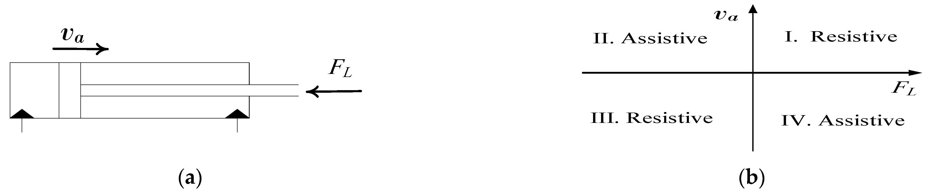
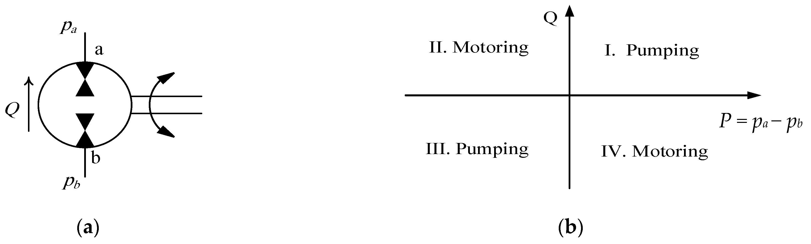
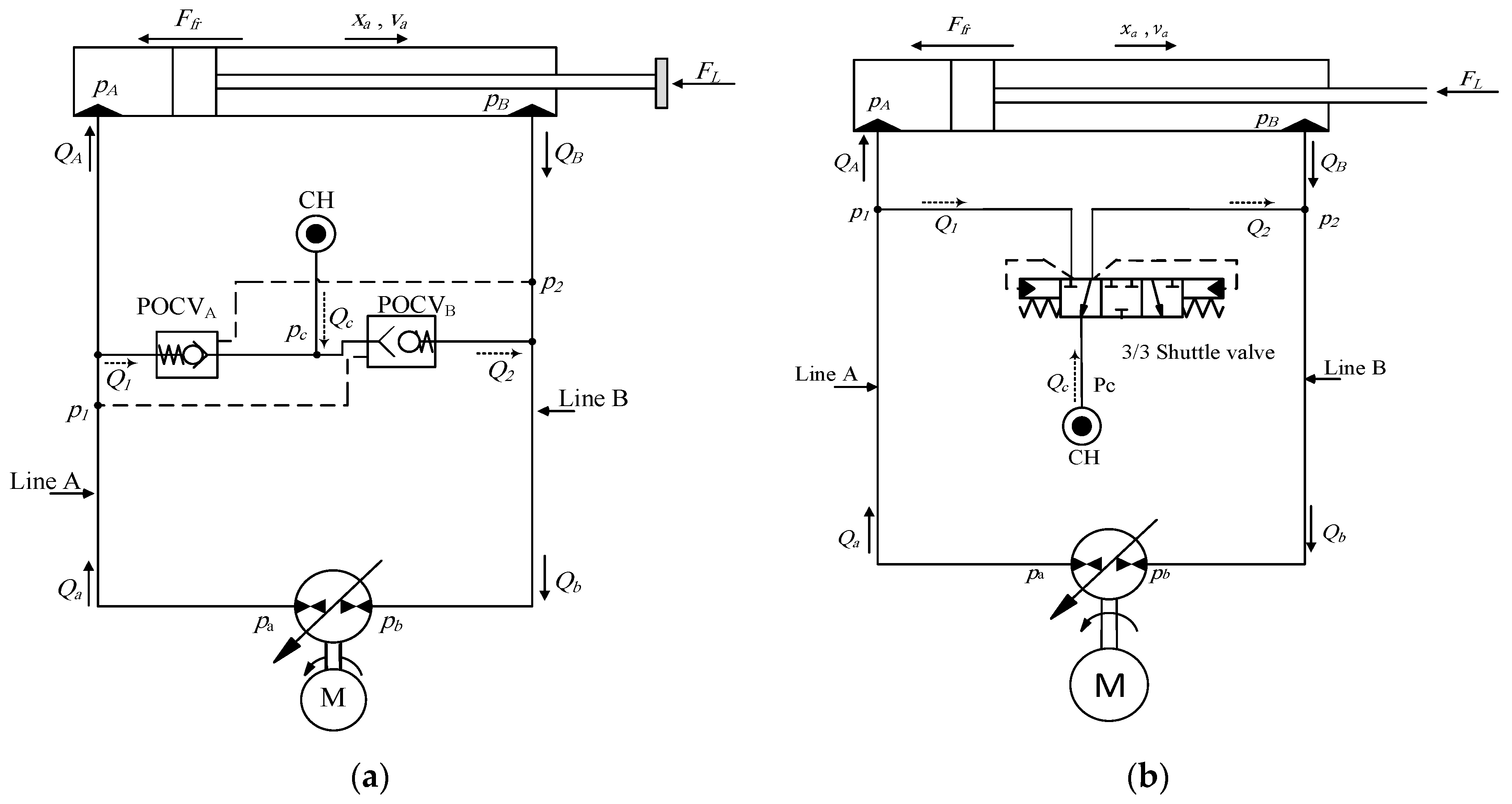
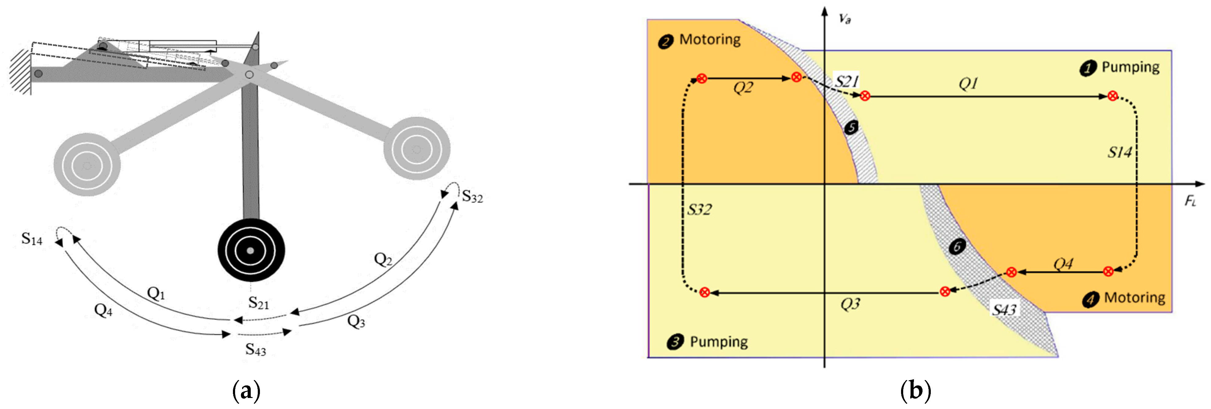
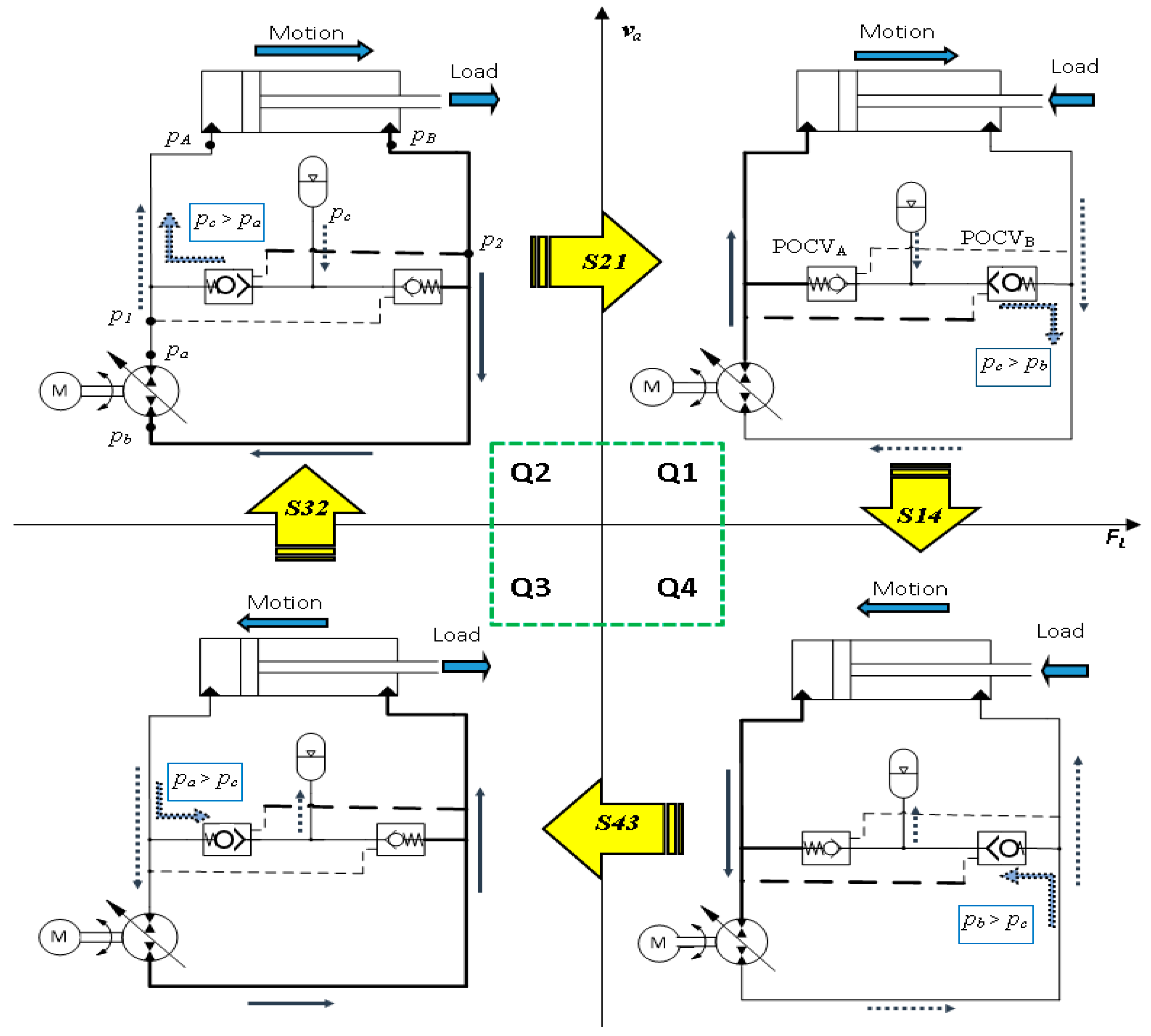
2. Operation of Pump-Controlled Circuits

Firstly, the quadrants of operation of actuator and pump, in pump-controlled circuits, are briefed. Based on motion and load directions, the cylinder operates in one of the four quadrants shown in Figure 1. In the first and third quadrants, the cylinder extends and retracts, respectively, against a resistive load. In both cases, energy is delivered from the hydraulic circuit to the actuator, to perform motion. In the second and forth quadrants, the assistive load drives the cylinder extension and retraction, respectively [18].
According to sign convention in Figure 2, when P and Q possess the same sign (first and third quadrants), the pump works in pumping mode; it receives energy from the prime mover and transfers it to the hydraulic circuit. When P and Q have different signs (second and fourth quadrants), the pump works in motoring mode; it receives energy from the hydraulic circuit and delivers it to the prime mover [18].
Figure 3 illustrates simplified drawings of the pump-controlled circuit that utilizes POCVs and the one that uses the CC-SHV. Each circuit comprises a variable-displacement bi-directional swash-plate piston pump, single-rod actuator, and low-pressure charge system (CH), along with the specified valves for flow compensation.
Following this point, the operation of a circuit that utilizes POCVs is detailed; however, the same explanation is applicable to the circuit with the CC-SHV. POCVs are opened by pilot signals from cross pressure lines as the circuit operates in the four quadrants of operation. Consider extending the actuator against the resistive external load, as shown in Figure 3 and Figure 4, the pump delivers flow Q in clockwise direction to the cap side of the cylinder through main transmission Line A. As the pressure in Line A builds up, it opens the cross-pilot-operated check valve, POCVB. Consequently, the charge line (CH) is connected to Line B, which allows flow ( Q b c ) to compensate for the cylinder differential flow. In this case, the main pump works in pumping mode and the actuator works in resistive mode. Figure 4 shows a schematic drawing of an excavator stick, actuated by a pump-controlled circuit in four quadrants of operation, along with circuit performance in the load-velocity plane. For this construction configuration, the sequence of operation is in the clockwise direction.
Figure 5 shows the different flow patterns in each of the four quadrants of operation for circuits represented in Figure 3 and Figure 4. The operational sequence is as follows: resistive extension (Q1), assistive retraction (Q4), resistive retraction (Q3), and assistive extension (Q2). the arrows between quadrants represent the switching zones. Switching zones between, each two successive quadrants, are denoted as S14, S43, S32, and S21. Observe that while the operational status (opened / closed) of the POCVs does not change at zones S14 and S32, operational status is switched at zones S43 and S21. Reconfiguration of the compensating valves causes abrupt interruption to the system dynamics. These variations are accompanied by changes in pump operating mode and actuator velocity. Thus, S43 and S21 are recognized as regions of potentially poor performance [18].

3. Modelling and Simulations

Mathematical models of the circuits with POCVs, and that with the CC-SHV, are detailed in our previous work [19]. Simulation studies are performed to identify the shape and position of the critical operating zones and to evaluate circuits’ performance in this zone. Simulation programs of both circuits are developed in MATLAB. Parameters and values of the JD-48 actuator and typical POCVs and CC-SHVs, used in simulations, are listed in Table 1. Simulation studies are performed for both constant and variable loading scenarios.

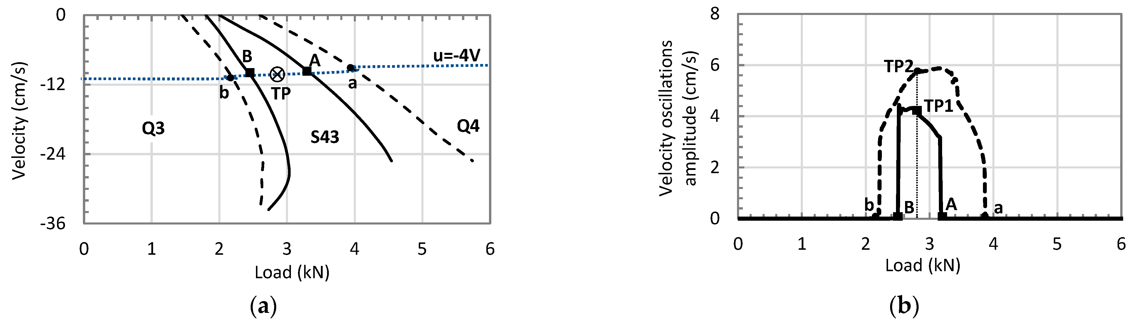
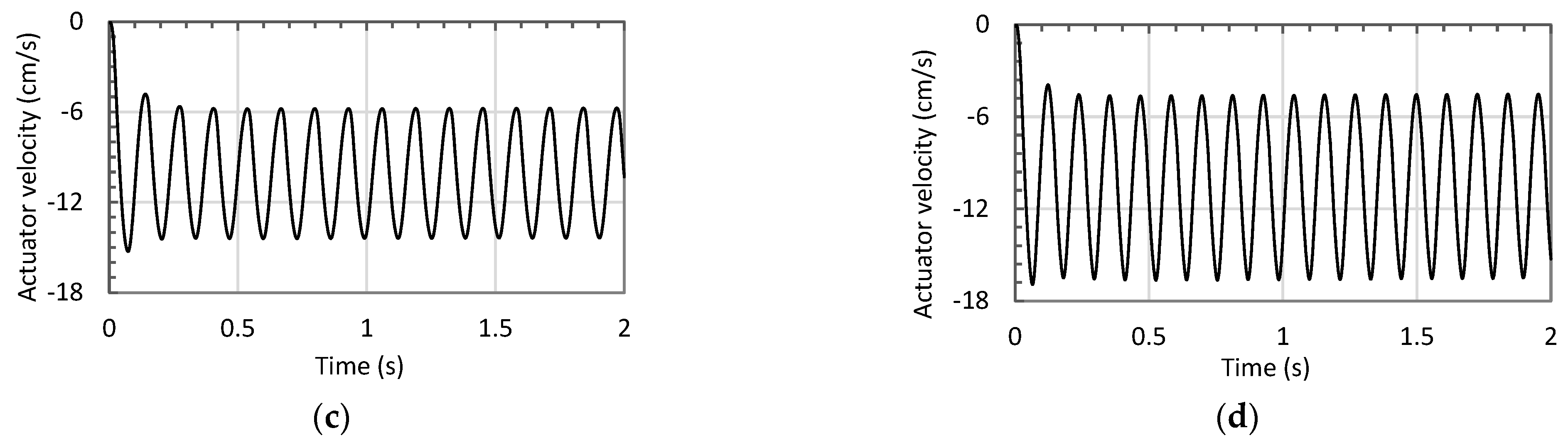
3.1. Simulations for Constant Loading Conditions

In this scenario, both circuits’ responses are simulated for a constant load and a step input control signal; simulation is repeated at different operating points covering all four quadrants of operation. Results are classified based on response quality. Accordingly, the poor performance zone is located on the FL-va plane for circuits with POCVs and the CC-SHV (area between two corresponding lines in Figure 6a); Figure 6b shows velocity oscillation amplitudes in critical zone for both circuits. Oscillative velocity response versus time at test points TP1 and TP2, illustrated in Figure 6b, is shown in Figure 6c,d for circuits with POCVs and the CC-SHV, respectively.
Referring to Figure 6, a comparison of the critical zone areas of both circuits shows that the circuit with the CC-SHV possesses a larger oscillatory zone compared to the circuit with POCVs; the area ratio is found to be 2.25:1. It is also noted that the circuit with the CC-SHV possesses higher velocity oscillation amplitude and frequency compared to circuits with POCVs. Table 2 summarizes the performance characteristics of both circuits in critical zone.

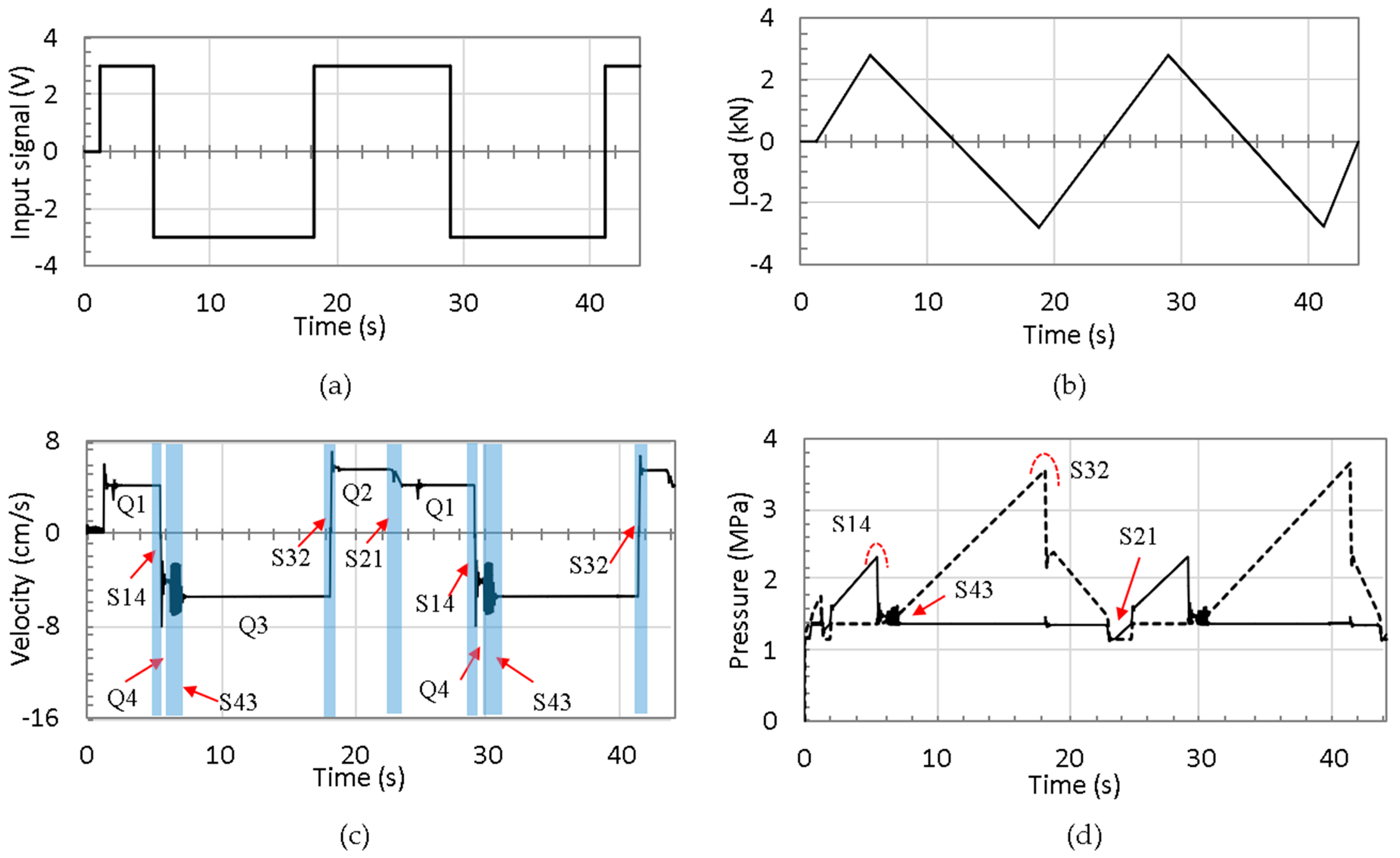
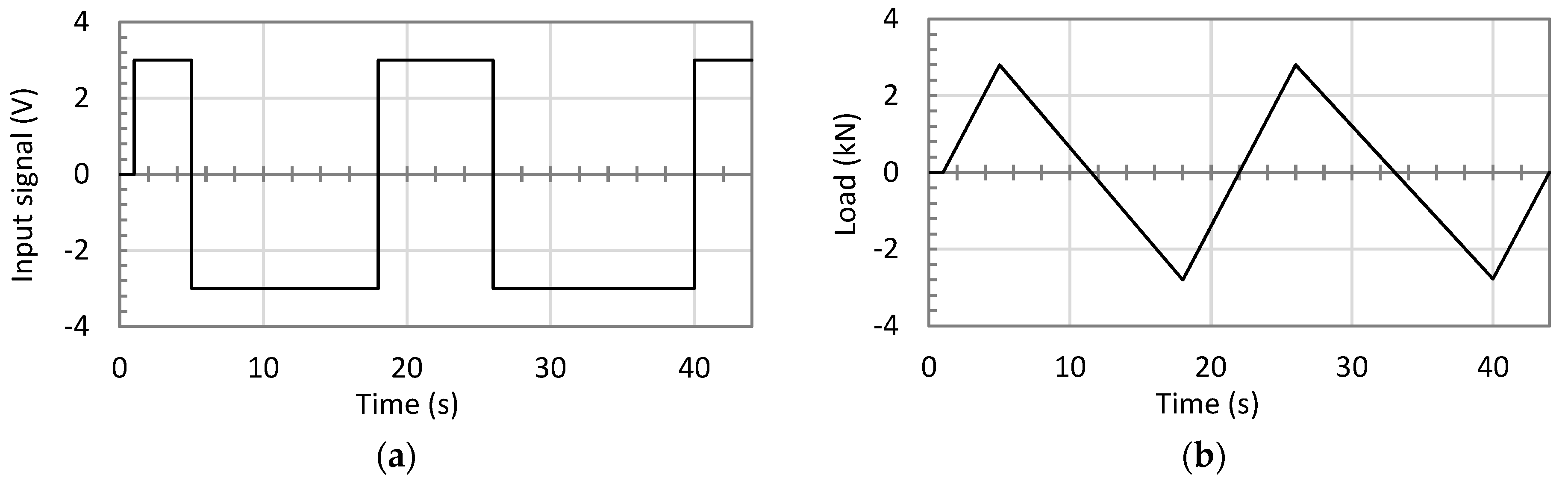
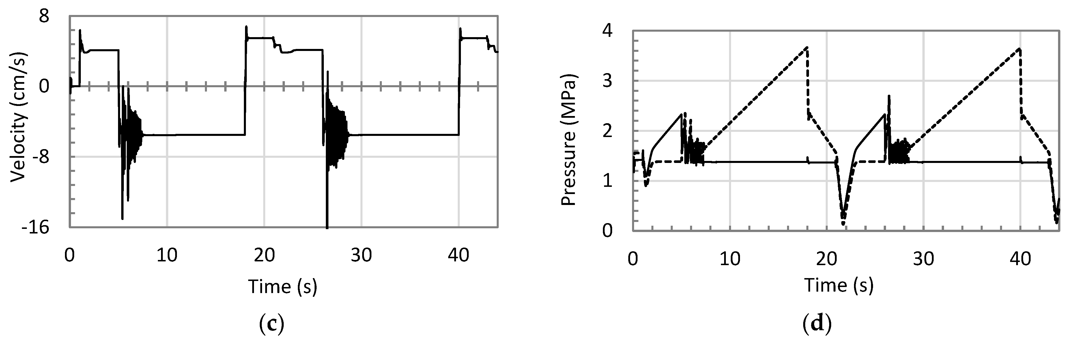
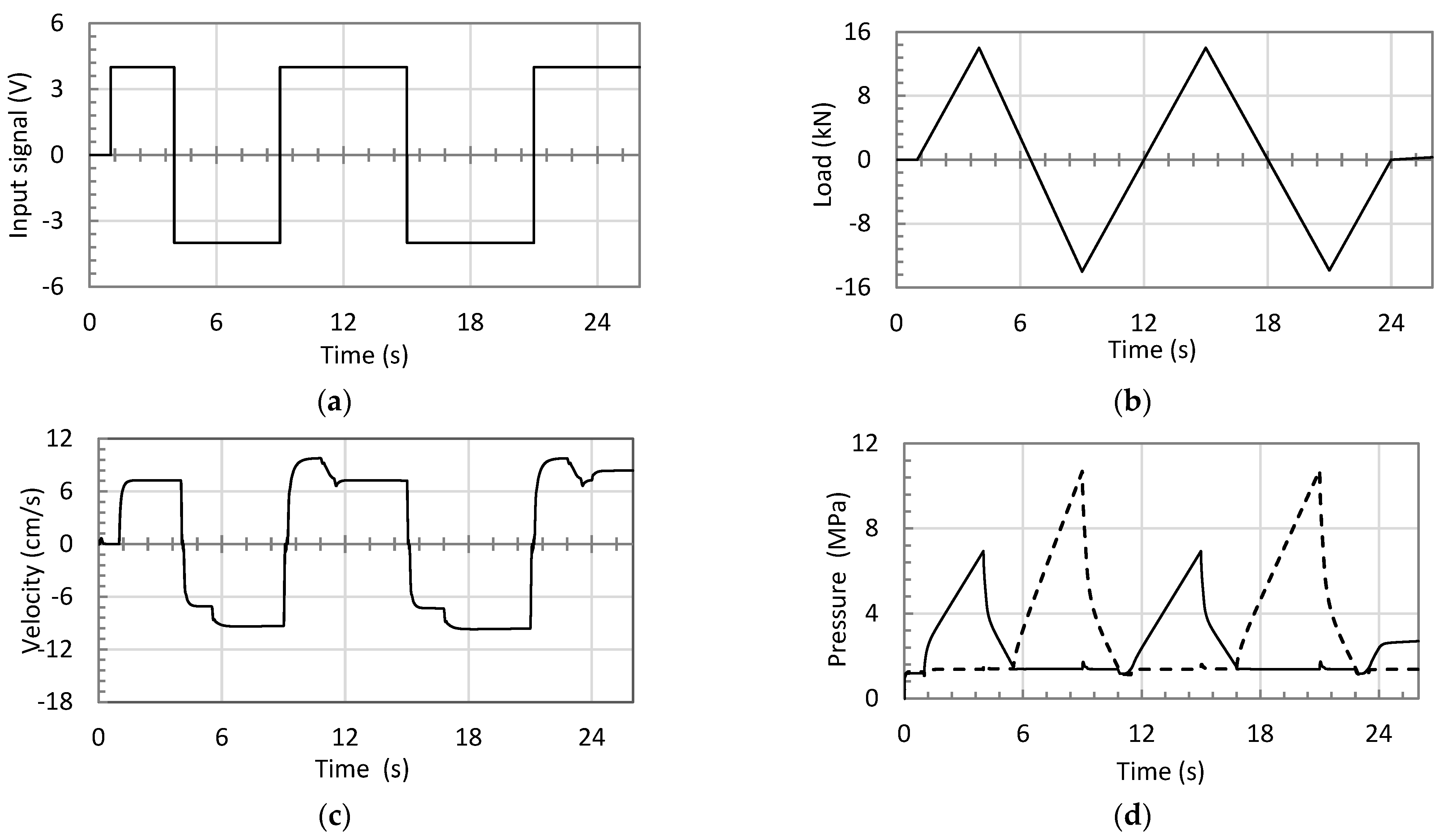
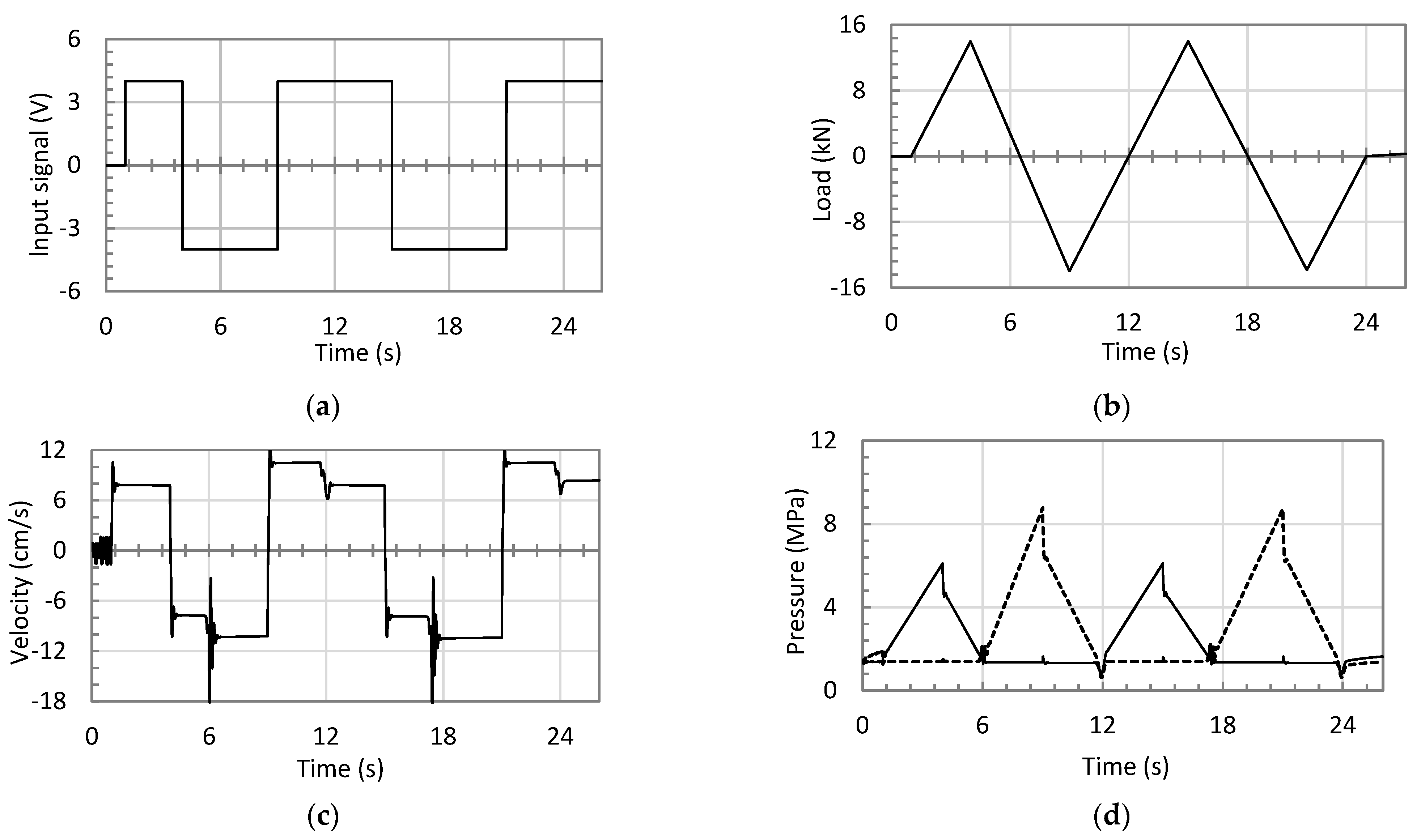
3.2. Simulations for Variable Loading Conditions

In this scenario, responses of both circuits are simulated for variable loading condition and a square input signal; this scenario emulates a real motion of an excavator link. Note that during one complete operating cycle of the actuator, the motion of the mass at the end of the stick generates different resistive and assistive loads that cover all four quadrants of operation. In this simulation, load pattern is approximated to a triangular-shaped pattern. The circuits’ performance is simulated at both low and high loading conditions. Simulations at low loading conditions are designed mainly to investigate stability issues, and high loading simulations examine circuit performance in realistic operations.
Figure 7 and Figure 8 show the responses of the circuits that use POCVs, and the one with the CC-SHV, in low loading conditions. Figure 7a and Figure 8a show the applied control signals, and Figure 7b and Figure 8b illustrate the triangular-shaped load patterns to circuits with POCVs and SHV, respectively. Figure 7c,d and Figure 8c,d show the actuator velocity and pressures at pump ports for corresponding circuits, respectively. Velocity and pressure plots, for both circuits, show acceptable non-oscillatory performance in all quadrants of operation and switching zones except for S43 (switching zone between 4th and 3rd quadrants).
Performance deterioration in form of pressure and velocity oscillations is noticed in both circuits in zone S43. The circuit with the CC-SHV shows more severe pressure and velocity oscillations in terms of amplitude, frequency, and duration as compared to circuit with POCVs. Amplitude of velocity oscillations are 2 and 3 cm/s that lasted for 0.5 and 1 s in circuits with POCVs and SHV, respectively. More deteriorated performance in circuits with SHVs is attributed to the coupled nature of the SHV, that affects both sides of the cylinder, simultaneously leading to more severe dynamical changes. In zone S21, a pressure drop is still observed in both circuits, particularly in circuit using the CC-SHV. No significant performance deterioration during zone S14 (switching zone between 1st and 4th quadrants) and zone S32 (switching zone between 2nd and 3rd quadrants) in both circuits. This is because switching occurs with the same configuration of the valves.
Figure 9 and Figure 10 illustrate the responses at high loading conditions for the circuits using POCVs and the CC-SHV, respectively. Figure 9a,b and Figure 10a,b illustrate the input control signals and triangular-shaped load patterns to circuits with POCVs and SHV, respectively. Figure 9c,d and Figure 10c,d demonstrate the actuators velocities and pressures at the pump ports for the corresponding circuits. Velocity and pressure plots show non-oscillatory performance in all modes of operation in circuit with POCVs, while few oscillation ripples are observed in circuit with SHV in switching zone S43.

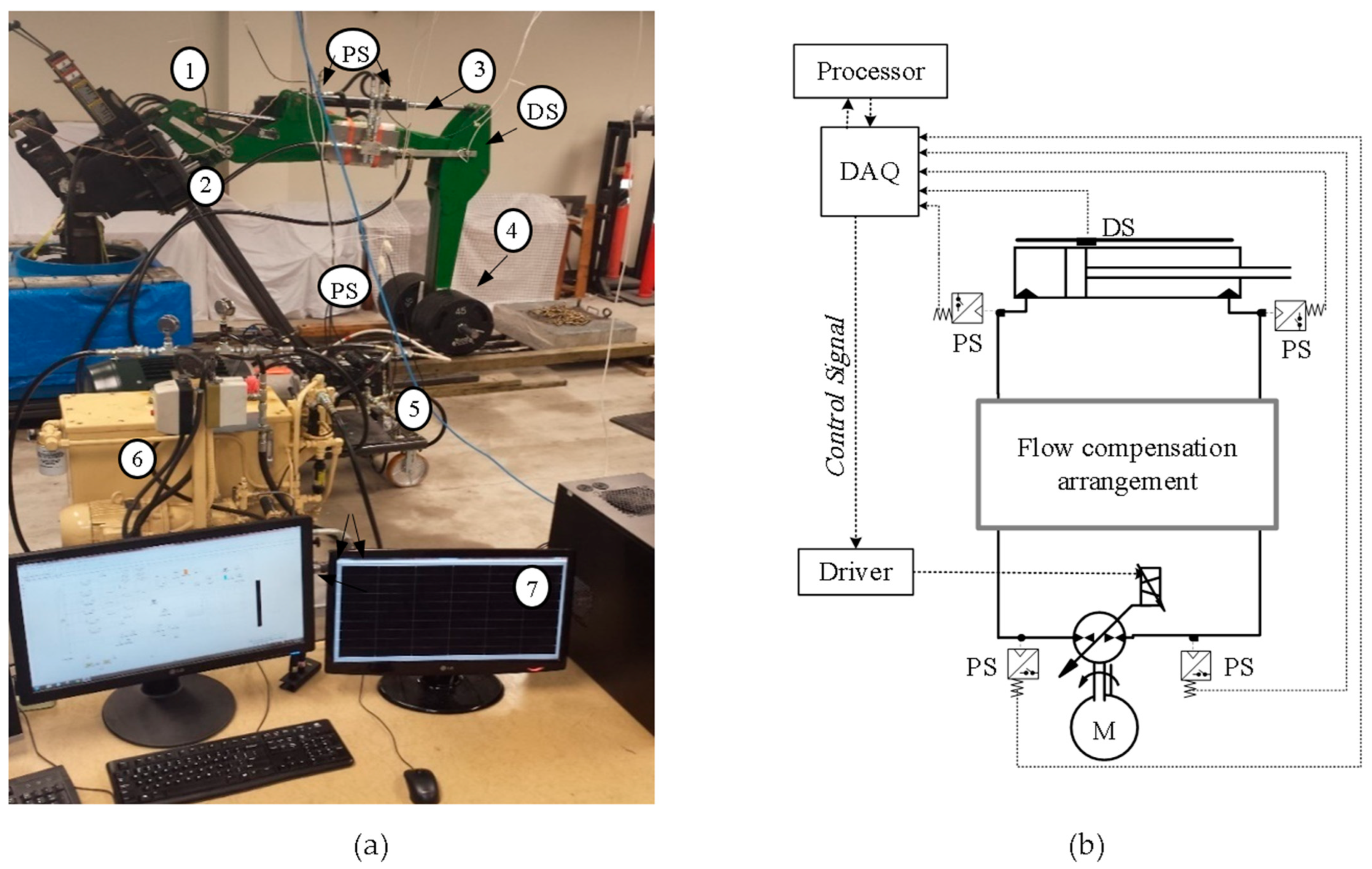
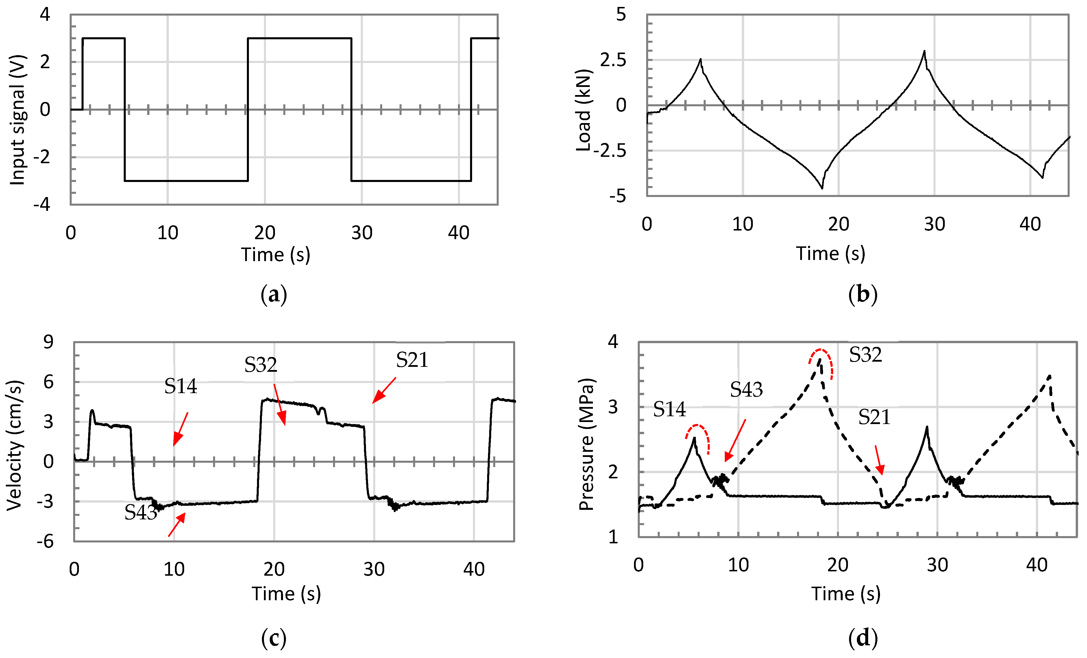
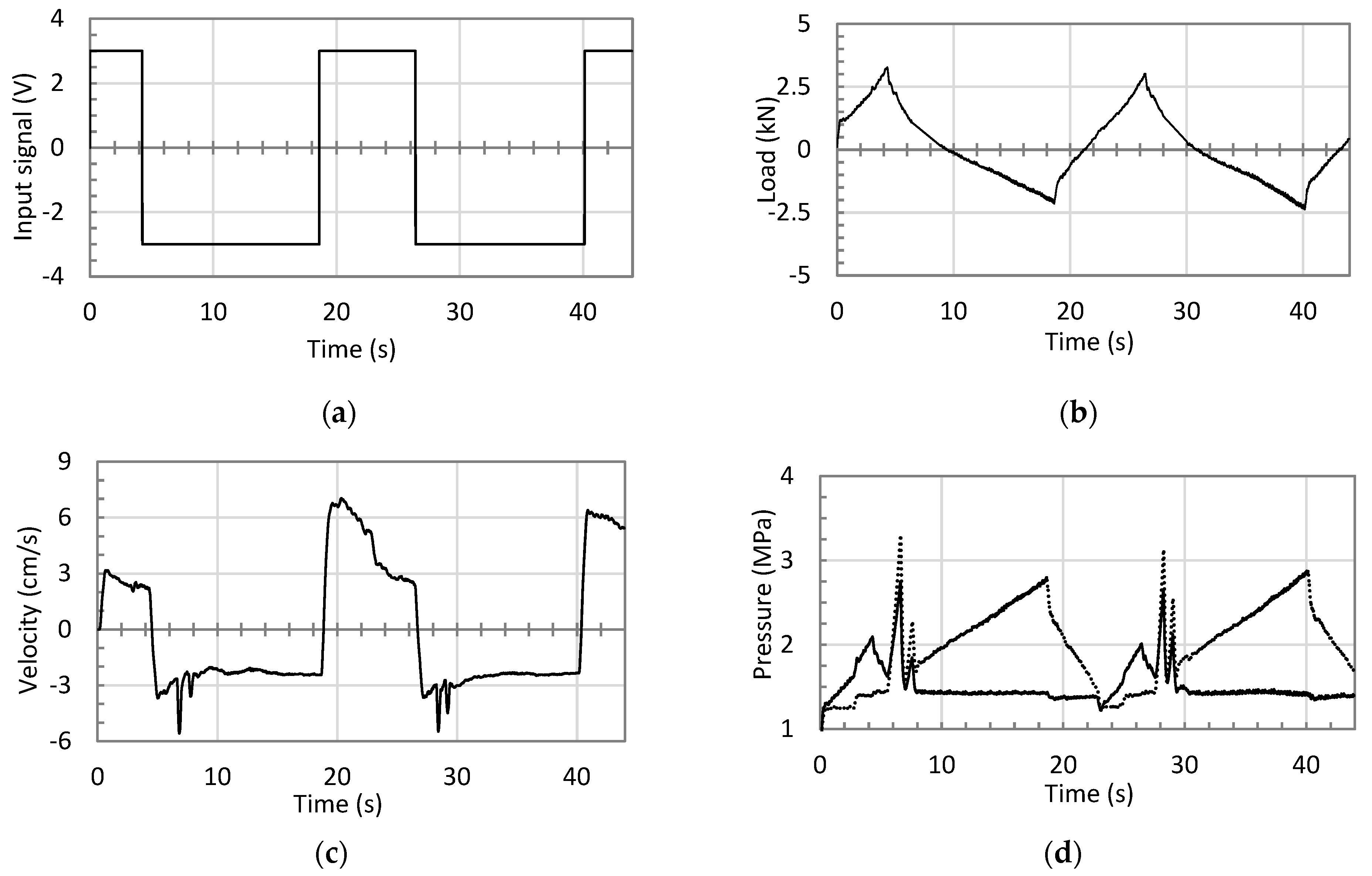
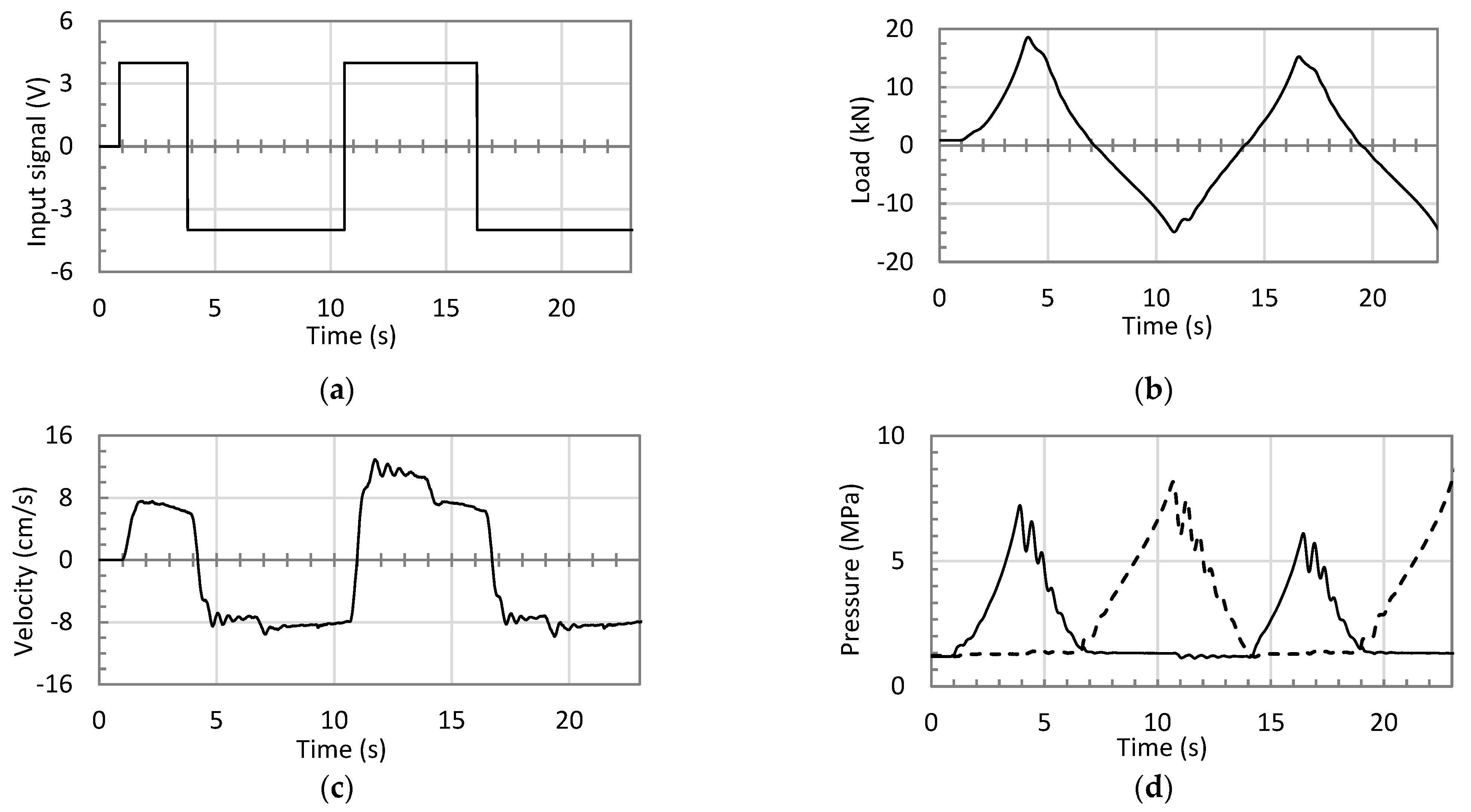
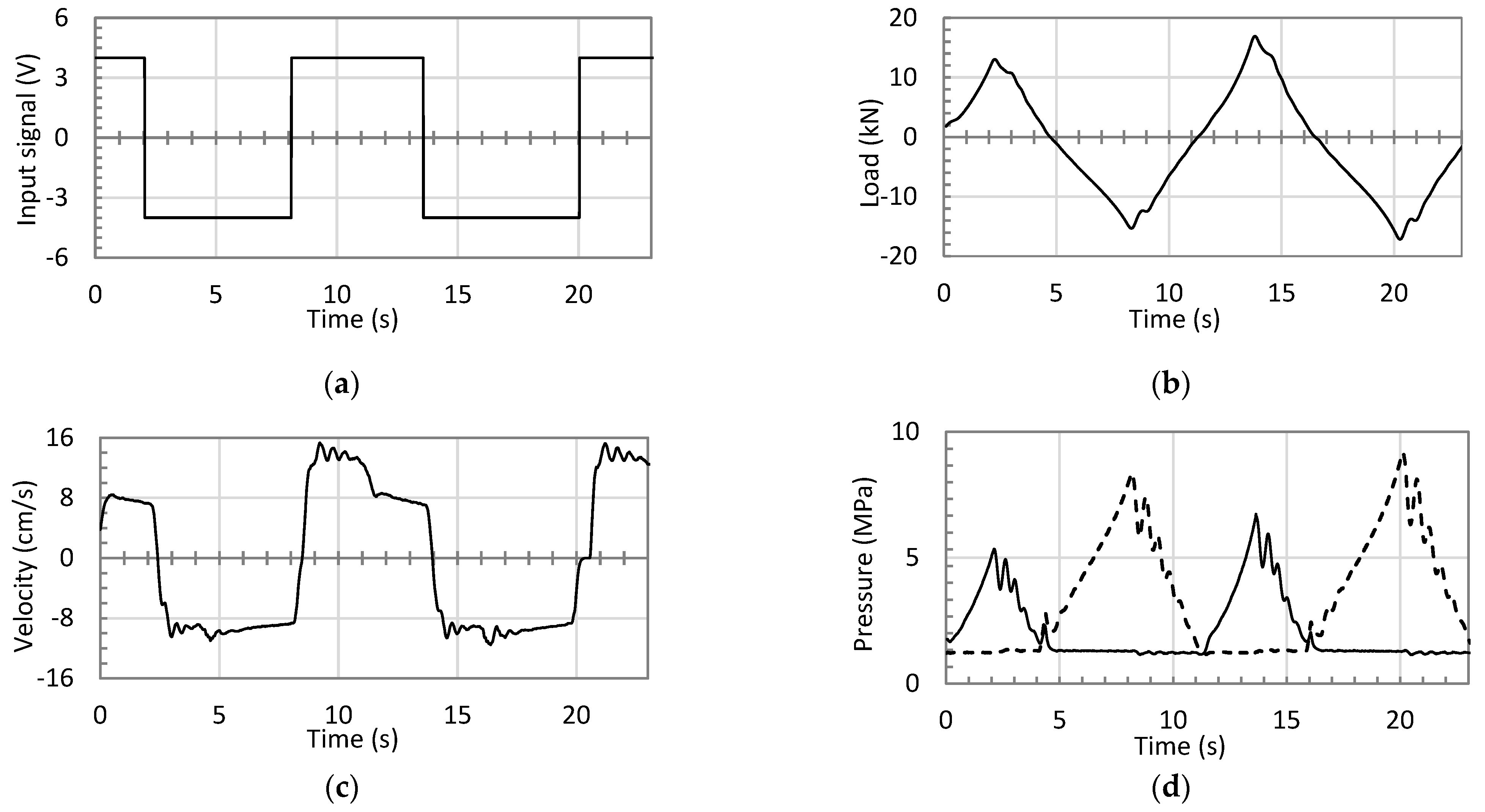
4. Experimental Evaluations

Figure 11 shows the test rig used in performing the experimental work and Table 3 summarizes its main specifications. The circuits with two POCVs, and that with the CC-SHV, are assembled and tested using the test rig. Tests are performed at variable loading conditions, where a square input signal is applied to the main pump to obtain cyclic motion of the actuator. Similar to simulation studies, both circuits are tested under low and high loading conditions, where masses of 41 kg and 368 kg are attached to the end of the stick link. All tests are carried out using an open loop control mode. Figure 12 and Figure 13 show responses of the circuits with POCVs and the CC-SHV in low loading conditions. Figure 12a and Figure 13a illustrate the input control signals to the corresponding circuit. A slight difference between input signals is attributed to the human factor, since control signals were manually applied for safety reasons. Figure 12b and Figure 13b show the load applied to the actuator due to the attached mass motion. Figure 12c,d and Figure 13c,d demonstrate the velocity and pressures of the corresponding circuits. Velocity and pressure plots show that performance is accepted in all quadrants of operation. Velocity and pressure plots further demonstrate the oscillatory behavior in the circuits with POCVs and the CC-SHV in the deteriorating performance zone S43. However, more severe pressure and velocity ripples are experienced in the circuit with the CC-SHV. The performance in zone S21 is not oscillatory, while slight velocity and pressure drops are noted in both circuits, particularly in the circuit using the CC-SHV. This pressure drop is limited, due to the activation of the anti-cavitation valves that are originally equipped into the pump housing.
Figure 14 and Figure 15 illustrate the responses at high loading conditions for circuits with POCVs and the CC-SHV, respectively. Figure 14a,b and Figure 15a,b show the manually applied control signals and the load applied to the corresponding circuit, respectively. Figure 14c,d and Figure 15c,d demonstrate the actuator velocity and pressures at pump ports as a function of time for the corresponding circuit. Few oscillations in the velocity and pressure curves are noted in both circuits, in switching zones S14 and S32, which can be attributed to the abrupt-change nature of the square input signal. Smoother input signals do not display these oscillations. Zone S21 shows a non-oscillatory behavior that is similar in both the circuits.
The velocity and pressure graphs demonstrate considerably smaller oscillatory responses of both circuits at switching zone S43, compared to those seen in low loading conditions. However, the oscillations are smaller in the circuit with POCVs as compared to the circuit with the CC-SHV. Higher ripples in circuits with SHVs is attributed to the effect of these valves on both sides of the circuit during switching, leading to vast dynamic changes. Figure 12, Figure 13, Figure 14 and Figure 15 demonstrate the enhanced performance of the circuit using POCVs, when compared to circuits using SHVs at low and high loading conditions.

5. Conclusions

Performances of the circuits that utilize two pilot-operated check valves, and that utilize a closed-center shuttle valve, are theoretically and experimentally investigated. Poor performance regions in the load-velocity plane show less critical area and oscillation severity in the circuit with POCVs as compared that with the CC-SHV. Velocity and pressure responses of the two circuits, in low and high variable loading conditions, show that the circuit with the CC-SHV possesses higher pressure and velocity ripples when compared to the circuit with POCVs. This can be attributed to the coupling nature of the SHV that simultaneously creates a sudden dynamic change at both sides of the circuit. The circuit with pilot-operated check valves experiences performance issues under low loading conditions, while showing an improved performance at higher loading conditions. From above discussions it is clear that the circuit with POCVs is more appropriate as a first-choice candidate (platform) for future modifications and upgrades of pump-controlled circuits.
Consent, portions of this work were partially presented in the first author’s PhD thesis at University of Manitoba mentioned in reference number 12 and can be reached at mspace.lib.umanitoba.ca (accessed 30 March 2023).

Author Contributions

Conceptualization, A.I. and N.S.; methodology, A.I. and N.S.; software, A.I. and M.T.; validation, A.I. and N.S.; formal analysis, A.I.; investigation, A.I.; data curation, A.I. and M.T.; writing—original draft preparation, A.I. and M.T.; writing—review and editing, A.I. and N.S.; visualization, A.I. and M.T.; supervision, N.S.; funding acquisition, N.S. All authors have read and agreed to the published version of the manuscript.

Funding

This research received fund from Natural Sciences and Engineering Research Council (NSERC) of Canada.

Institutional Review Board Statement

Not applicable.

Informed Consent Statement

Not applicable.

Data Availability Statement

Relevant data can be reached at mspace.lib.umanitoba.ca (accessed 30 March 2023).

Conflicts of Interest

The authors declare no conflict of interest.

References

  1. Ritelli, G.F.; Vacca, A. Energetic and Dynamic Impact of Counterbalance Valves in Fluid Power Machines. Energy Convers. Manag. 2013, 76, 701–711. [Google Scholar] [CrossRef]
  2. Zimmerman, J.D.; Pelosi, M.; Williamson, C.A.; Ivantysynova, M. Energy Consumption of an LS Excavator Hydraulic System. In Proceedings of the ASME International Mechanical Engineering Congress and Exposition (IMECE), Seattle, WA, USA, 15–16 January 2007; pp. 12–15. [Google Scholar]
  3. Goljat, S.; Tič, V.; Lovrec, D. Advantages of Pump Controlled Electro Hydraulic Actuators. In Proceedings of the 7th International Conference of New Technologies, Development and Application, Sarajevo, Bosnia and Herzegovina, 24–26 June 2021. [Google Scholar]
  4. Rahmfeld, R.; Ivantysynova, M. Developing and Control of Energy Saving Hydraulic Servo Drives. In Proceedings of the Fluid Power Net International Symposium (FPNI-PhD), Hamburg, Germany, 20–22 September 2000; pp. 167–180. [Google Scholar]
  5. Scherer, M.; Geimer, M.; Weiss, B. Contribution on Control Strategies of Flow-On-Demand Hydraulic Circuits. In Proceedings of the 13th Scandinavian International Conference on Fluid Power, SICFP2013, Linköping, Sweden, 3–5 June 2013. [Google Scholar]
  6. Hewett, J.A. Hydraulic Circuit Flow Control. U.S. Patent 5,329,767, 19 July 1994. [Google Scholar]
  7. Hippalgaonkar, R.; Ivantysynova, M. A Series-Parallel Hydraulic Hybrid Mini-Excavator with Displacement Controlled Actuators. In Proceedings of the 13th Scandinavian International Conference on Fluid Power, SICFP2013, Linköping, Sweden, 3–5 June 2013. [Google Scholar]
  8. Grabbel, J.; Ivantysynova, M. Model Adaptation for Robust Control Design of Hydraulic Joint Servo Actuators. In Proceedings of the 4th International Symposium on Fluid Power Transmission and Control (ICFP 2003), Wuhan, China, 28 August 2003. [Google Scholar]
  9. Rahmfeld, R.; Ivantysynova, M. Displacement Controlled Linear Actuator with Differential Cylinder-a Way to Save Primary Energy in mobile machines. In Proceedings of the 5th International Conference on Fluid Power Transmission and Control (ICFP 2001), Hangzhou, China, 3–5 April 2001. [Google Scholar]
  10. Rahmfeld, R. Development and Control of Energy Saving Hydraulic Servo Drives for Mobile Machines. Ph.D. Thesis, TUHH, Hamburg, Germany, 2002. [Google Scholar]
  11. Williamson, C.; Ivantysynova, M. Pump Mode Prediction for Four quadrant Velocity Control of Valveless Hydraulic Actuators. In Proceedings of the 7th JFPS International Symposium on Fluid Power, Toyama, Japan, 15–16 September 2008; pp. 323–328. [Google Scholar]
  12. Wang, L.; Book, W.J.; Huggins, J.D. A Hydraulic Circuit for Single Rod Cylinder. J. Dyn. Syst. Meas. Control ASME 2012, 134, 011019. [Google Scholar] [CrossRef]
  13. Yuming, S.; Imam, A.; Wu, C.; Sepehri, N. Stability Study of a Pump-Controlled Circuit for Single Rod Cylinders via the Concept of Lyapunov Exponents. In Proceedings of the ASME/BATH 2017 Symposium on Fluid Power and Motion Control, Sarasota, FL, USA, 16–19 October 2017. [Google Scholar]
  14. Caliskan, H.; Balkan, T.; Platin, E.B. A Complete Analysis and a Novel Solution for Instability in Pump Controlled Asymmetric Actuators. J. Dyn. Syst. Meas. Control 2015, 137, 091008. [Google Scholar] [CrossRef]
  15. Imam, A.; Rafiq, M.; Jalayeri, E.; Sepehri, N. Design, Implementation and Evaluation of a Pump-Controlled Circuit for Single Rod Actuators. Actuators 2017, 6, 10. [Google Scholar] [CrossRef]
  16. Imam, A.; Sepehri, N. Pump-Controlled Hydraulic Circuits for Operating a Differential Hydraulic Actuator. U.S. Patent 10927856B2, 23 February 2021. [Google Scholar]
  17. Li, R.; Sun, Q.; Ding, X.; Zhang, Y.; Yuan, W.; Wu, T. Review of Flow-Matching Technology for Hydraulic Systems. MDPI Process. 2022, 10, 2482. [Google Scholar] [CrossRef]
  18. Imam, A. Pump-Controlled Hydraulic Circuits for Single-Rod Actuators: New Designs and Performance Evaluation; MSpace, University of Manitoba: Winnipeg, MB, Canada, 2020. [Google Scholar]
  19. Imam, A.; Rafiq, M.; Zeljko, T.; Sepehri, N. Improving the Performance of Pump-Controlled Circuits for Single-Rod Actuator. Actuators 2019, 8, 26. [Google Scholar] [CrossRef]
Figure 1. Single-rod cylinder: (a) sign convention; (b) quadrants of operation.
Actuators 12 00193 g001
Figure 2. Hydrostatic pump: (a) sign convention; (b) quadrants of operation.
Actuators 12 00193 g002
Figure 3. Pump-controlled circuits that utilize: (a) pilot operated check valves; (b) a 3/3 closed-center shuttle valve; in the first quadrant of operation, CH denotes charge system.
Actuators 12 00193 g003
Figure 4. An excavator stick actuated by a pump-controlled circuit in four quadrants of operation: (a) schematic drawing; (b) circuit performance in the load-velocity plane.
Actuators 12 00193 g004
Figure 5. Flow patterns in four quadrants of operation (Q1, Q2, Q3, and Q4) and switching zones (S14, S43, S32, and S21) of circuit that utilizes pilot-operated check valve in the load-velocity plane.
Actuators 12 00193 g005
Figure 6. Critical zones for circuit that utilize POCVs and that use CC-SHV: (a) location for circuit with POCVs (solid line) and circuit with CC-SHV (dashed line); (b) velocity oscillation amplitude at constant input signal (u = −4 V) and different loads, for circuit with POCVs (solid line) and for circuit with CC-SHV (dashed line); (c,d) actuator velocity responses for circuits with POCVs and CC-SHV for step signal input of −4 V at test points TP1 and TP2 shown in (c).
Actuators 12 00193 g006aActuators 12 00193 g006b
Figure 7. Simulation results for performance of the circuit with two pilot-operated check valves at low loading conditions given data in Table 1: (a) input control signal; (b) variable load of ± 3 kN; (c) actuator velocity; (d) pressures at pump ports a (solid line) and b (dotted line).
Actuators 12 00193 g007
Figure 8. Simulation results for performance of the circuit with closed-center shuttle valve at low loading conditions given data in Table 1: (a) input signal; (b) variable load of ±3 kN; (c) actuator velocity versus time; (d) pressures at pump ports a (solid line) and b (dotted line).
Actuators 12 00193 g008aActuators 12 00193 g008b
Figure 9. Simulation results for performance of the circuit with two pilot-operated check valves at high loading conditions given data in Table 1: (a) input control signal; (b) variable load of ± 15 kN; (c) actuator velocity versus time; (d) pressures at pump ports a (solid line) and b (dotted line).
Actuators 12 00193 g009
Figure 10. Simulation results for performance of the circuit with closed-center shuttle valve at high loading conditions given data in Table 1: (a) input control signal; (b) variable load of ±15 kN; (c) actuator velocity versus time; (d) pressures at pump ports a (solid line) and b (dotted line).
Actuators 12 00193 g010
Figure 11. Test rig: (a) a photo shows, (1) JD-48 backhoe attachment; (2) supporting structure; (3) actuator (4) load; (5) main pump unit; (6) charge pump unit; (7) control and monitoring station; (PS) pressure sensors; (DS) displacement sensor; (b) control schematic.
Actuators 12 00193 g011
Figure 12. Performance of the circuit with pilot-operated check valves for a 41 kg attached mass: (a) input signal; (b) applied load; (c) actuator velocity; (d) pressures at the pump ports a (solid line) and b (dotted line).
Actuators 12 00193 g012
Figure 13. Performance of the circuit that utilizes a closed-center shuttle valve for a 41 kg attached mass: (a) input signal; (b) applied load; (c) actuator velocity; (d) pressures at the pump ports a (solid line) and b (dotted line).
Actuators 12 00193 g013
Figure 14. Performance of the circuit that utilizes pilot-operated check valves for a 368 kg attached mass: (a) input signal; (b) applied load; (c) actuator velocity; (d) pressures at the pump ports a (solid line) and b (dotted line).
Actuators 12 00193 g014
Figure 15. Performance of the circuit that utilizes a closed-center shuttle valve for a 368 kg attached mass (a) input signal; (b) applied load; (c) actuator velocity; (d) pressures at pump ports a (solid line) and b (dotted line).
Actuators 12 00193 g015
Table 1. Values of parameters of circuits shown in Figure 3.
ParameterDefinitionValues
A a Area of piston cap side 31.67 × 10 4 [ m 2 ]
A b Area of piston rod side 23.75 × 10 4 [ m 2 ]
K o i l Effective bulk modulus 0.689 × 10 9 [ P a ]
P c Charge pressure 1.38 [ M P a ]
M e q Equivalent mass 0 400 [ k g ]
A l k Valve leakage area 0 [ m 2 ]
A m a x Valve max flow area 25 × 10 6 [ m 2 ]
P c r Valve cracking pressure 0.2 [ M P a ]
P o m x Valve maximum opening pressure 0.5 [ M P a ]
Table 2. Performance index of the simulated circuits.
Performance Index at Critical Zone (S43)Circuit
POCVsCC-SHV
Mean velocity (cm/s)−9.8−10.4
Oscillation amplitude (cm/s)±3.5±5.9
Oscillation frequency (Hz)7.58.5
Critical zone size (ratio)12.25
Table 3. Test rig specifications.
Main ComponentsSpecification
1Actuator cap-side area, area ratio and stroke 31.67 cm2, 0.75, 55 cm.
2Main pump unitSauer-Danfoss (42 series), 28 cm3/rev, electrically-controlled variable swash-plate piston pump.
3Charge pump unitNorthman (VPVC-F40-A1), 1–2 MPa adjustable van pump.
PSPressure transducer Ashcroft, k1 series, 0–20 MPa, accuracy 0.5%.
DSDisplacement sensorBourns encoder, accuracy 8 μm.
POCVPilot-operated check valvesSun-hydraulics CKCB series, 0.2 MPa cracking pressure; 3:1 pilot ratio
CC-SHVClosed-center shuttle valve, Sun-hydraulics DSCL series, 0.2 MPa cracking pressure.
Disclaimer/Publisher’s Note: The statements, opinions and data contained in all publications are solely those of the individual author(s) and contributor(s) and not of MDPI and/or the editor(s). MDPI and/or the editor(s) disclaim responsibility for any injury to people or property resulting from any ideas, methods, instructions or products referred to in the content.

