1. Introduction
Morphing wing engineering has accompanied the development of the aeronautic technology since its very first moves: the transformation of the first aircraft to metal structure has some-how inhibited the capability of its wing skeleton at the pilot’s command, paving the way to more articulated control surface architectures. On the other hand, the increasing speed of the flying machines had determined the augmentation of the loads, and the need of more robust systems to ensure a duly operation. It is not a case that it is possible to find some early patents on morphing dated 1917 by a firm named Varioplane [
1]. By the way, the proposed solution is very similar to what the engineers realized on-board of the legendary AFTI experiments, performed on a modified version of the F111, in the ’80 [
2]. Along all that period, the available technology was not capable of providing reliable and viable solutions to the problem; and the situation seemed frozen until the DARPA commissioned Northrop-Grumman to investigate the possibility of creating morphing wings by the use of shape memory alloys. The conclusion of that study, brilliantly carried out by the team led by Jay Kudva, was surprising: morphing wings could be conceived (even if for a scaled model), but with contemporary technology [
3]. Since then, remarkable steps forward have been done and flying experiments have been not so rare in the scientific and technologic community. The remarkable example of the Mission Adaptive Compliant Wing project (MACW) did make a step forward in the assessment of the idea, and it can be considered the first actual innovation from the ’20, by substituting a classical kinematic structure, with a fully distributed deformation architecture [
4]. But the former concept did also evolve, taking advantage of the electromechanical developments, providing stronger and stronger actuators, with smaller and smaller dimensions, capable to be allocated in the small rooms of the structure, while evolved mechanisms did provide adequate robustness and easiness of realization. The advent of novel, breakthrough production process like 3D manufacturing, did definitely give another reason to increase the confidence in morphing systems: the need of many parts, each different from the others was not a showstopper anymore. It should be clearly clarified that all the enlisted technologies are not widely mature yet to be fully implemented on a commercial, or a combat airplane. However, the path to the completion of the trip seems shorter than before. A wide distinction does today classify the morphing systems in compliant or kinematic: each of them has its advantages and disadvantages, and the final solution it is not clear, yet. A systematic comparison about the two architectures is beyond the scope of this paper, which instead aims at presenting a novel architecture, based on the same kinematic principles introduced by Varioplane, re-taken within the F111 research, and further matured during many other activities in the recent years (like SARISTU [
5], and VCCTEF projects [
6], for instance), to arrive to a prototype ready to fly in the very near future and installed in the uncomfortable room of a winglet, while standing within very tight weight and room constraints [
7]. Such a result was unthinkable up to few years ago, and may represent itself a major milestone in the development of the morphing technology.
The Project of AIRGREEN2 (AG2) [
8,
9], funded within the Clean Sky 2 REG-IADP frame, under the industrial guidance of Leonardo Aerospace Division, technically coordinated by CIRA, focuses on some of the above technologies. The structure and the technology development path of this Project were conceived to select the most promising technologies relevant to life-cycle design, morphing, advanced aerodynamics and load control and alleviation, maturate them according to a well-established process and arrive, when applicable, at a final demonstration in relevant environment and in flight.
AIRGREEN2 is a well-balanced Consortium in terms of types, roles and nationalities of the Institutions [
8,
9]. Four universities (Politecnico di Milano, Politecnico di Torino, Università di Napoli “Federico”, Università di Pisa) contribute to the academic and innovative content of the research. Nine SMEs and Industries (HELLENIC AEROSPACE INDUSTRIES, SICAMB, SIEMENS, FOXBIT, AEROSOFT, ITALSYSTEM, NOVOTECH, TECNAM, UMBRA) assure the needed compliance to the industrial requirements. Finally, five research centers (CIRA, ONERA, IMAST, CNR, ENEA) provide an adequate mediation between the concepts and their evolution and transition towards the industrial products. A total budget of 9.0 M€ with a funding equal to 7.8 M€, over a duration of 7 years (2015–2022) is shared among the just mentioned institutions, with a sharing of 37% for the academies, 21% for the research centers and 41% to the SMEs and industries. The project is coordinated by CIRA, whose background on aerospace technologies assures a close monitoring of the activities and a particularly active role in relevant aspects of the Project, as the adaptive morphing.
The present paper deals with a specific subsystem of the adaptive winglet developed in AIRGREEN2, that is to say, the movable parts and relevant kinematic chains. The role of this subsystem is to enhance the aerodynamic efficiency of the wing and reduce the stress level by actively altering the load distribution along the span. The just mentioned winglet is framed within a research scenario targeting additional functionalities for this type of device. Several investigations, in fact, highlight the advantages coming from the possibility of altering geometric parameters. To cite some example: in [
10,
11] the impact of the cant angle on aircraft efficiency is investigated in terms of aircraft performance and control; in [
12] the twist angle is also investigated considering the torsional elasticity and its impact on the dynamic of the aircraft; in [
13] the impact of the just mentioned geometric parameters and also of the aspect ratio and of the toe and sweep angles is investigated. Practical applications of the morphing technology can be then found out at different TRL levels. Among the others one recalls: the full size flapped winglet tested in wind tunnel facility [
14]; the variable cant angle winglet enabled by a dedicated corrugated skin [
15]; the flight test of a foldable winglet actuated by a SMA system [
16].
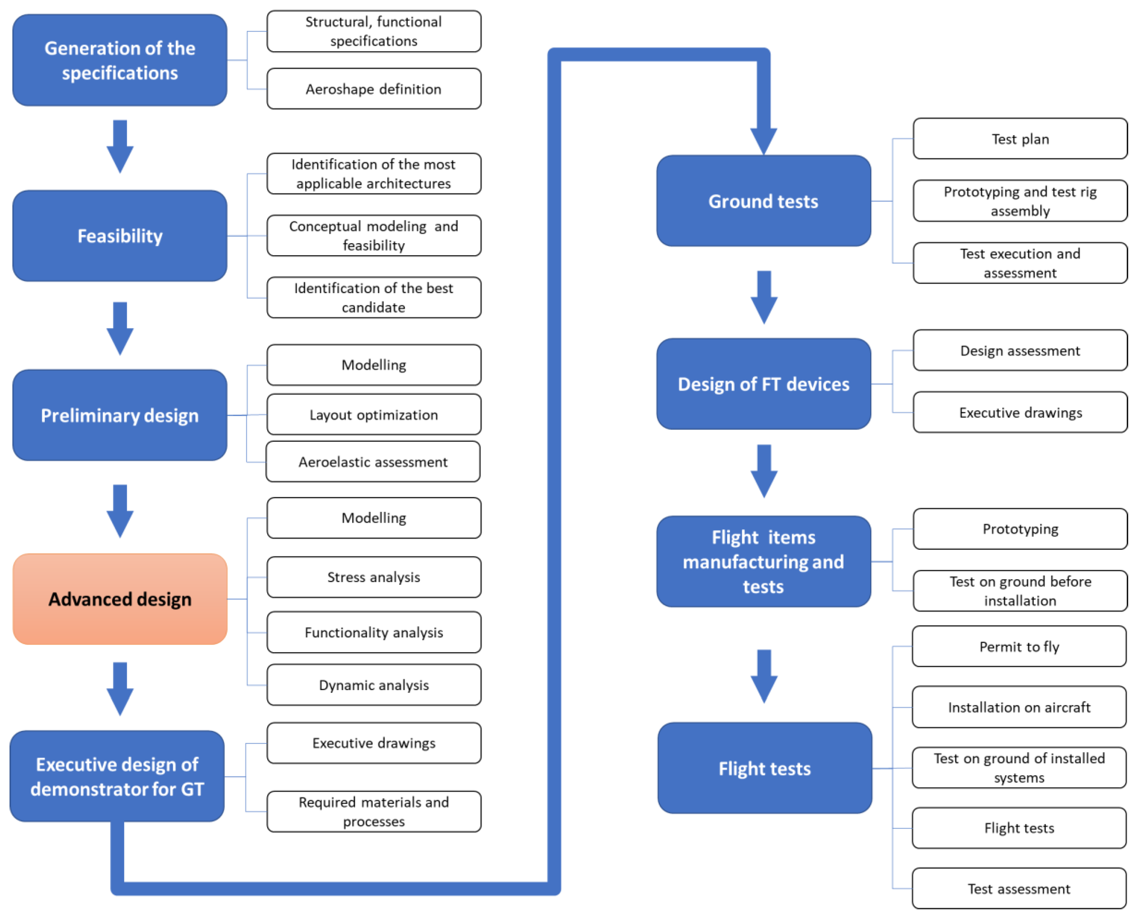
In this work, two aspects are mainly investigated: the functionality, here intended as the capability of the system to produce needed deflection, and the load bearing ability. The kinematic chains that transmit the movement from linear actuators to the finger-like flap mechanisms were conceived to adequately amplify the displacements to achieve large deflections. This peculiarity imposes the adoption of dedicated modelling tools, capable to manage the intrinsic non-linearity of the system. A dedicated global development plan was defined for the winglet. It is shown in
Figure 1. The first step is the generation of the specifications on the basis of the requirements at aircraft level. This phase also includes the definition of the aeroshapes in clean and morphed configuration. Then, in the “feasibility” task the architecture potentially applicable are investigated by means of light models. By means of dedicated criteria the most promising architecture is selected. At this point the preliminary design is addressed; this phase foresees the realization of a conceptual FE model, the optimization of the main design parameters and the aeroelastic assessment through an additional suited stick model of the winglet. Then the “Advanced design” task is faced. Its block was highlighted since the activities presented in the present work are part of it. In this phase, a refined FE model of the winglet is realized and stress, functionality and dynamic analyses are implemented. The activities described in this work are part of the advanced design and focuses on the movable part. The executive design is then addressed with the aim of realizing a prototype for the demonstration on ground. Though the ground tests (GT) the load bearing capability and the functionality are verified and eventual problems identified for the next design assessment. At this point, the executive drawings of the items for the fight tests (FT) are finalized. Left and right hand versions of the winglet are thus manufactured. Tests on ground are then performed to verify their functionality and load bearing capability in view of the final qualification to get the permit-to-fly. After this step they are installed on the aircraft and the verification of the fully integrated structure and of the different subsystems addressed. Finally, the flight tests are performed.
The work is organized following the different steps of the research. At first, a critical discussion is presented on the requirements at aircraft level and the specifications generated for the morphing system. In this section the process that led to the layout investigated in the next part is explained. Then, the design strategy is illustrated with specific focus on the tools used for the modelling and on the strategy identified to reproduce the different details that characterize the movable parts of the AWL, that is to say, actuators, kinematic transmission chains and flap finger-like mechanisms. Then, after having investigated the consistency of the model, the numerical results are presented. At first, a modal analysis was implemented to get the main information on the dynamic of the structure and on its overall rigidity. Then, a correlation among the main kinematic parameters was attempted, linking the stroke of the actuators to the deflection produced. After having framed the kinematic aspects, the focus has shifted on the robustness of the structure, investigating its behavior and achieved stress level under the action of assigned external loads. Finally, a critical overview of the results is provided, tracking a comparison between the initial requirements and the numerical predictions. The work ends with a summary on what presented and on the next steps of the research.
2. Requirements and Specifications
The reference aircraft considered in the present work is the 90-passenger regional turboprop aircraft equipped with a natural laminar flow wing developed by Leonardo Company in the framework of the Clean Sky 2 AG2 project [
8]. The NLF wing design considered multi-point optimizations for cruise, climb and low-speed flow conditions (see [
17,
18] for more details). Additionally, a wing load control function was investigated in order to obtain the best aerodynamic effects in terms of wing span load distribution and reduce structural loads by a combination of conventional (aileron) and unconventional devices (winglet and wingtip).
Active winglets were considered to enhance wing aerodynamic efficiency in off-design conditions (up to 2% of L/D improvement) and alleviate structural loads (up to 3% of reduction in root bending moment) during aircraft manoeuvres [
19]. The high-level requirements of the morphing winglet are listed in
Table 1 including and safety related implications of actuators failures. Two independent morphing surfaces (upper and lower) guided by two separate actuators and related actuation chains, one for each surface, were assumed. A major potential advantage of this architecture is the possibility to move the individual surfaces either synchronously or independently to different angles (twist). L/D improvements are achieved by separately controlling the downward deflections of the control surfaces in climb and cruise conditions. On the structural side, the wing bending and torsion control is accomplished by acting on a single surface through tailored outward deflections. Furthermore, such a configuration may improve the lateral control in one engine inoperative (OEI) failures and mitigate the safety risks associated with critical failure cases, such as jamming of one EMA and the partial loss of the winglet control. Due to the limited bandwidth of the state-of-the-art electromechanical actuators, it was proposed to adopt a feed-forward static controller, meaning a direct link between the rotation of primary control surfaces and the winglet control surfaces, implemented as a gear ratio relating the winglet deflections to the deflection of the elevator, ailerons and rudder during manoeuvres. The developed Manoeuvre Load Alleviation (MLA) controller is discussed in [
12] whereas details on the related performance are discussed in [
19] in both static and dynamic conditions, by considering both symmetric and antisymmetric deflections in the range [−15°, 5°]. The work demonstrated a reduction in the wing bending moment of 2.5% at the root and 82.6% at the tip, by a symmetric deflection of both morphing winglet tabs during a static pull up manoeuvre with load factor
.
4. Advanced Design
Dedicated tests have been designed in order to verify the capability of the structure of the movable parts and related hinges, lugs and the kinematic chain, to withstand inside the design loads prescribed by the operational envelope.
Since the moving parts have a finger-like configuration, two typical tests, for both external and internal flaps, have been considered with the aim to validate the requirements [
20]:
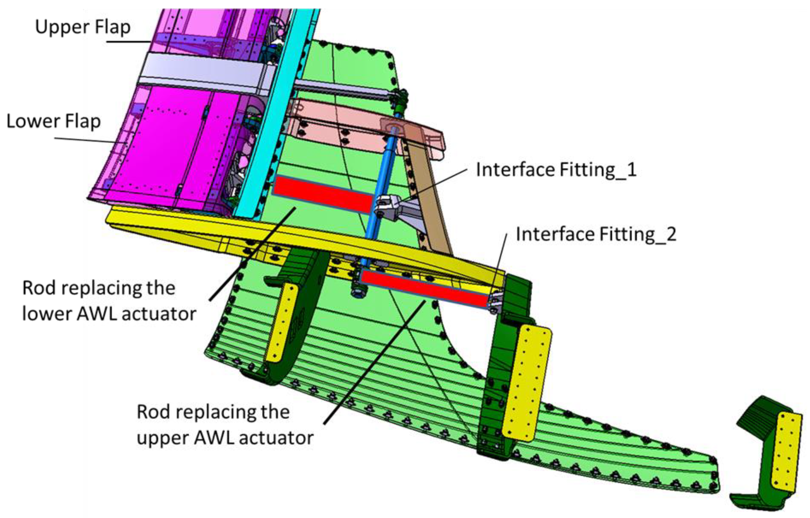
The first test is conceived by applying the load as follows: a set of saddles arranged on the entire chord of the flap (so that the inner and outer fingers of the flap are clamped together), pulled at the CoG in chordwise of each finger (
Figure 4). In this way, the total hinge moment is applied with respect to the main rotation axis (that of the entire flap), with the rotation inhibited by the kinematic chain of the flap control constrained by a rigid rod to replace the related actuator (
Figure 5). From this test, the internal constraints between two fingers are excluded since the rigid saddles block the rotational DOF of the external finger with respect to the internal one.
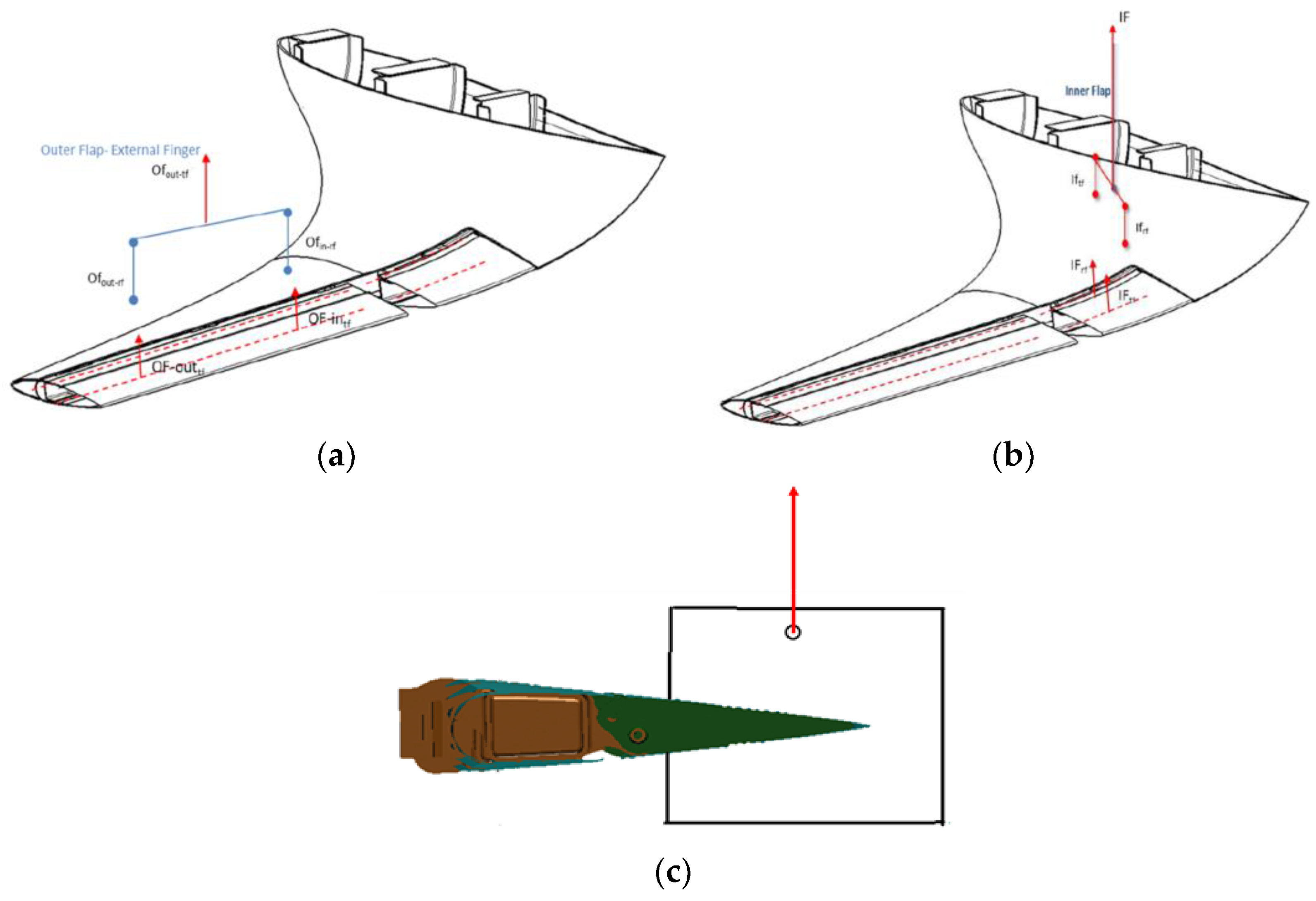
The second test is conceived by applying the load as follows: a set of shorter saddles, arranged on the chord of the external finger only with the aim to verify the external finger and related internal mechanisms to withstand the critical loads (
Figure 6). This test is representative for the parts excluded from the first test, that is: relative rotation hinge of the external finger with respect to the internal one and respective return rod, in addition of course to the finger itself.
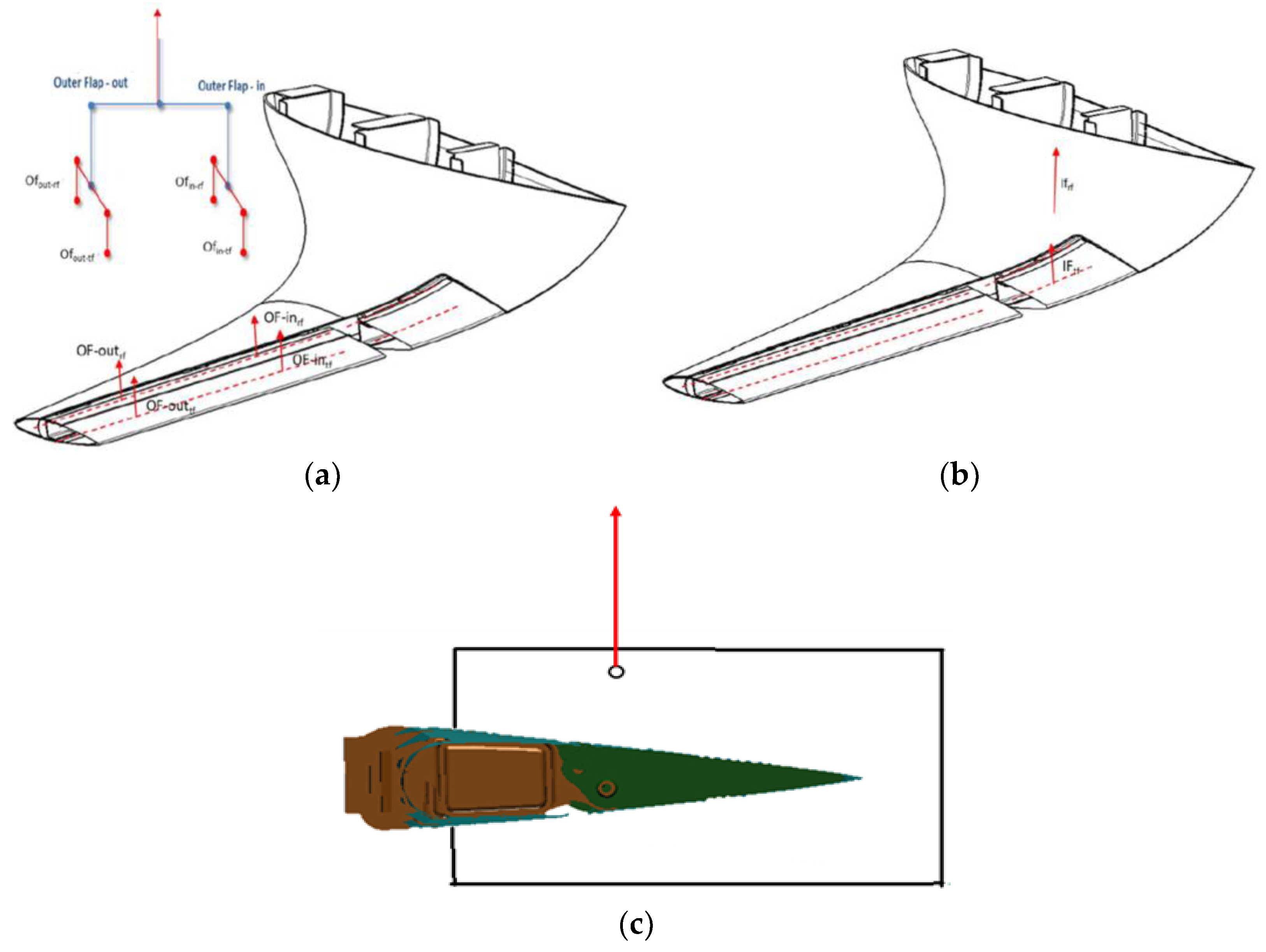
The AWL movable flaps Ground Static Test System includes a Test Rig as support system, loading system and measurement system (
Figure 7a). The Test Rig guarantees the possibility of testing the test specimen with exact support condition to simulate the test conditions. The loading system is realized by means a hydraulic jack meeting the accuracy requirement during loading, and ensuring that all the load cases of test specimen can be exactly simulated. The Test rig is completed by the levers system in charge of distributing spanwise concentrated loads introduced by hydraulic jacks on top of the truss. Dedicated saddles are designed to apply the loads (
Figure 7b,c).
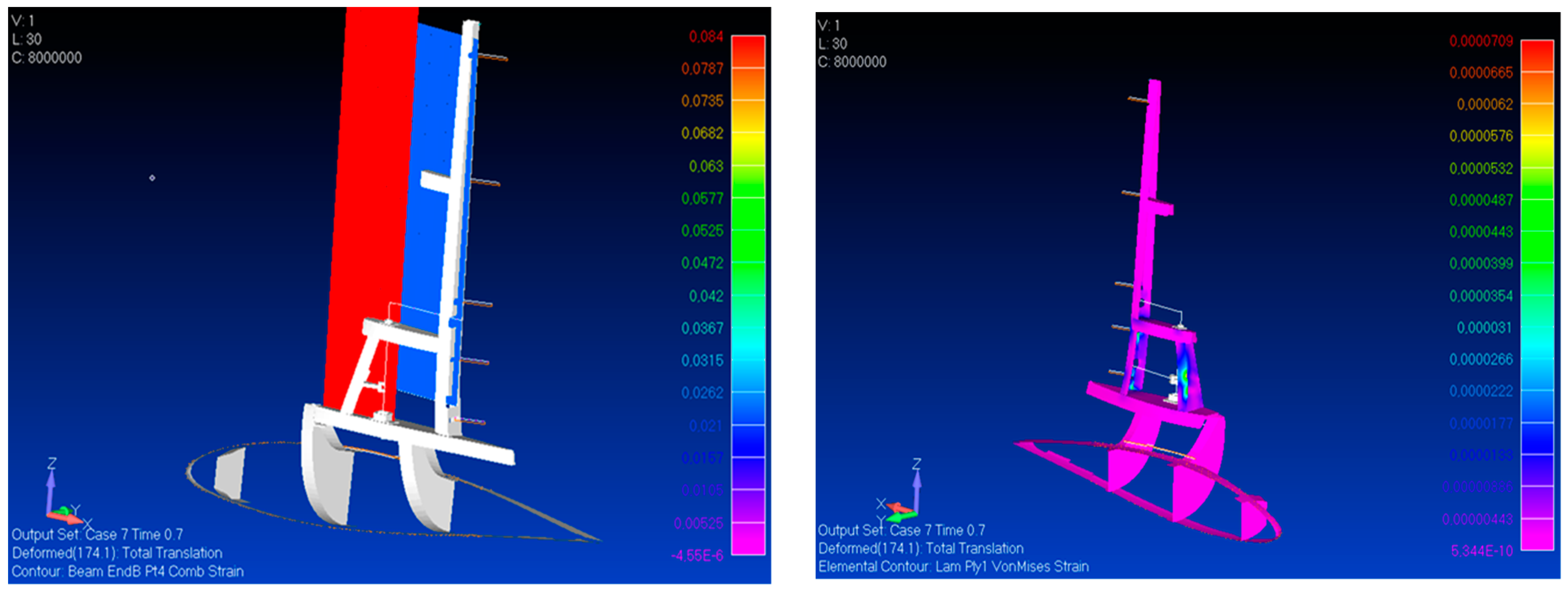
Since the movable parts working modality foresees large displacements and rotations, a dedicated non-linear modelling approach was considered [
21]. To this scope, the SOL 400 solver of MSC/Nastran was used both to describe the deflection of the movable parts of the winglet and estimate the stress level under the most severe load conditions [
22].
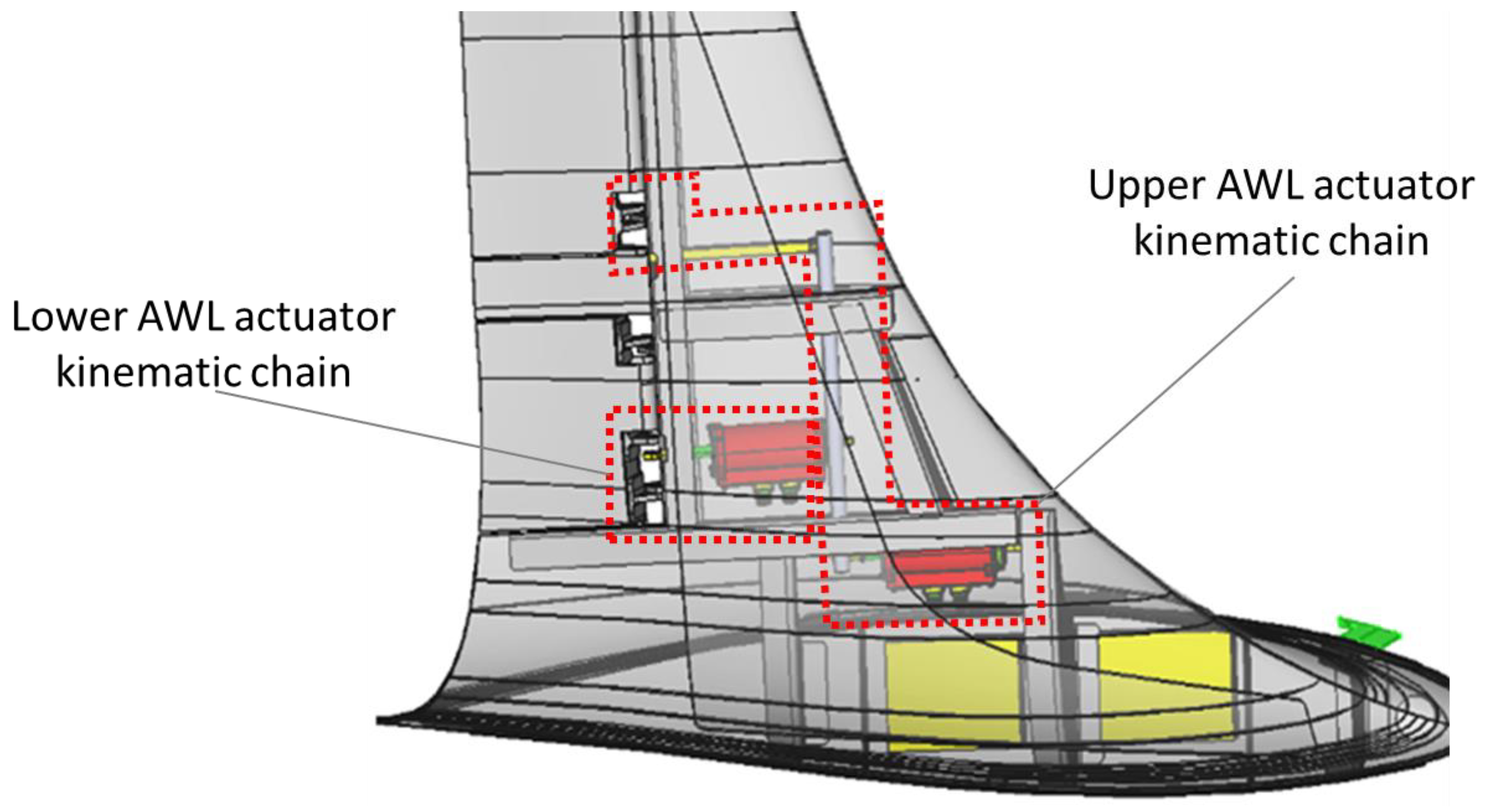
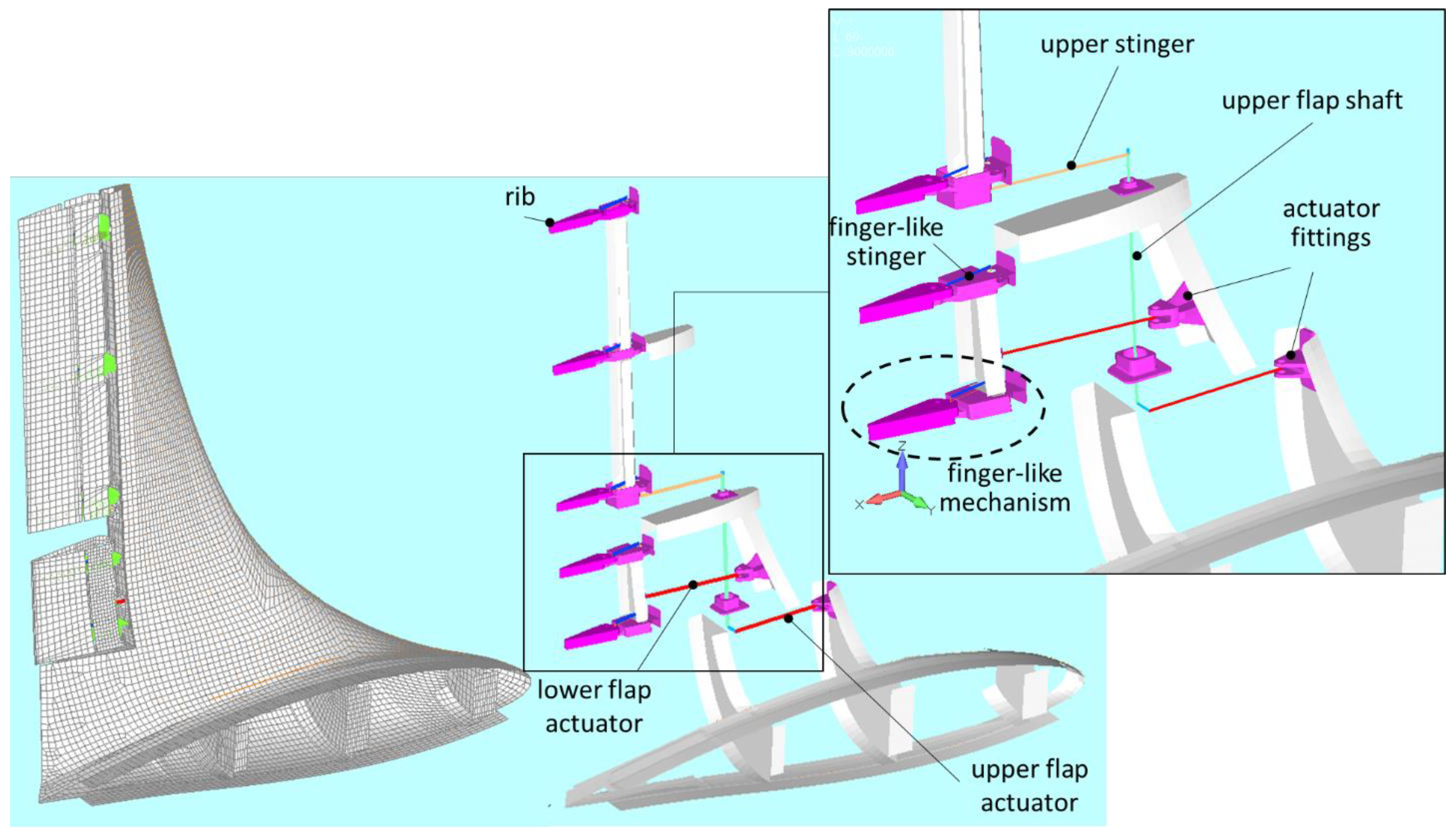
The action of the linear actuators was simulated by means of fictious thermal distortions applied on their representative line elements. In this way, their expansion/contraction are practically acted out as stroke in one sense and in the opposite one. To guarantee an adequate representativeness of the kinematic chains, the same axial stiffness of the actuators was assigned to their representative bar elements. All the remaining parts of the kinematic chains were modelled through beam-like elements. The joints among the parts were modelled through RBE2 rigid elements, releasing the DOF around their axis. This type of strategy was implemented since for the specific non-linear solver adopted, the release of the DOFs at the edges of the beam elements is not allowed. Solid elements were used for the ribs and the actuator fittings, being made of milled bulk parts. Finally, the skin was modelled through plate elements. In
Figure 8, the model of the AWL (left) and a detail of the kinematic chain (right) are illustrated. In the detail, the finger-like mechanism driving the flap deflection was highlighted and the three main parts, that is to say, the trailing edge the intermediate rib the stinger crossing the rear spar are evident. Another important detail is the shaft that characterizes the upper flap kinematic chain.
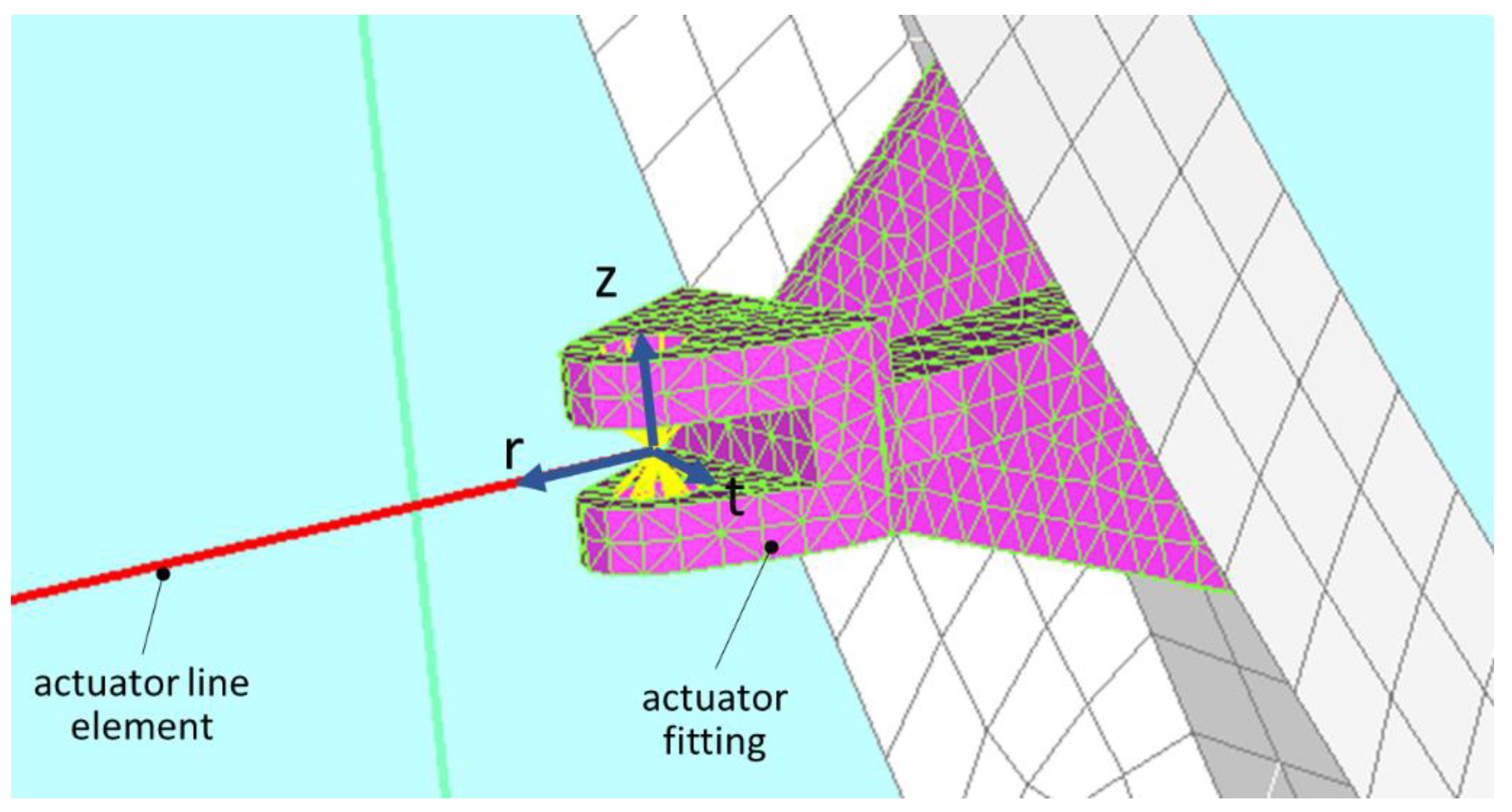
The hinge setting was a really delicate task. In fact, from one side, releasing more DOFs than necessary can lead to an undetermined structure and, from the other side, blocking unnecessary DOFs can cause an incorrect simulation of the working of the kinematic chain and potentially the arise of unrealistic stress concentrations. Another important aspect is the correct alignment of the different parts to avoid the involvement of unnecessary DOFs in the movement of the components. The actuators, in the real demonstrator, are linked to the fittings by means of ball joints. This kind of connection was not blindly modelled to avoid undetermined configurations: in fact, the rotational DOF around the actuator axes were blocked. It is however worth to note that in the real demonstrator the rotation of the actuator around their axes is hindered by the small room. To have an adequate control on the DOF on these joints and on the other ones in the kinematic chains, local cylindrical reference frames were defined. The reference systems of all the pin connections were defined assuming the z axis coincident to the pin direction. In the schematic of
Figure 9 a detail of the modelling of the actuator-fitting joint is illustrated with the local reference system. A spider element (tinted yellow in scheme) was used to connect the lug nodes to the center of the joint. Coherently to what mentioned above, the rotational DOF around the
r axis was blocked.
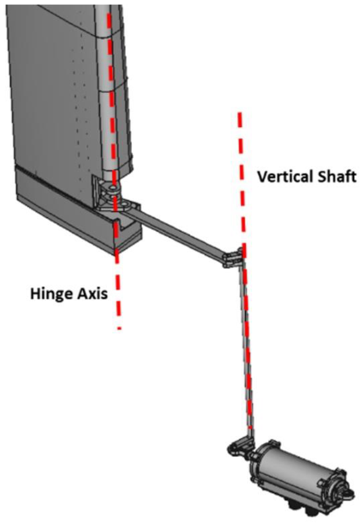
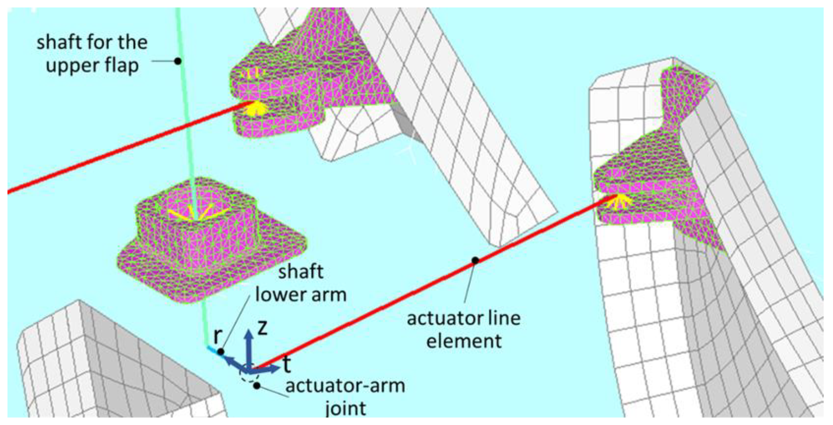
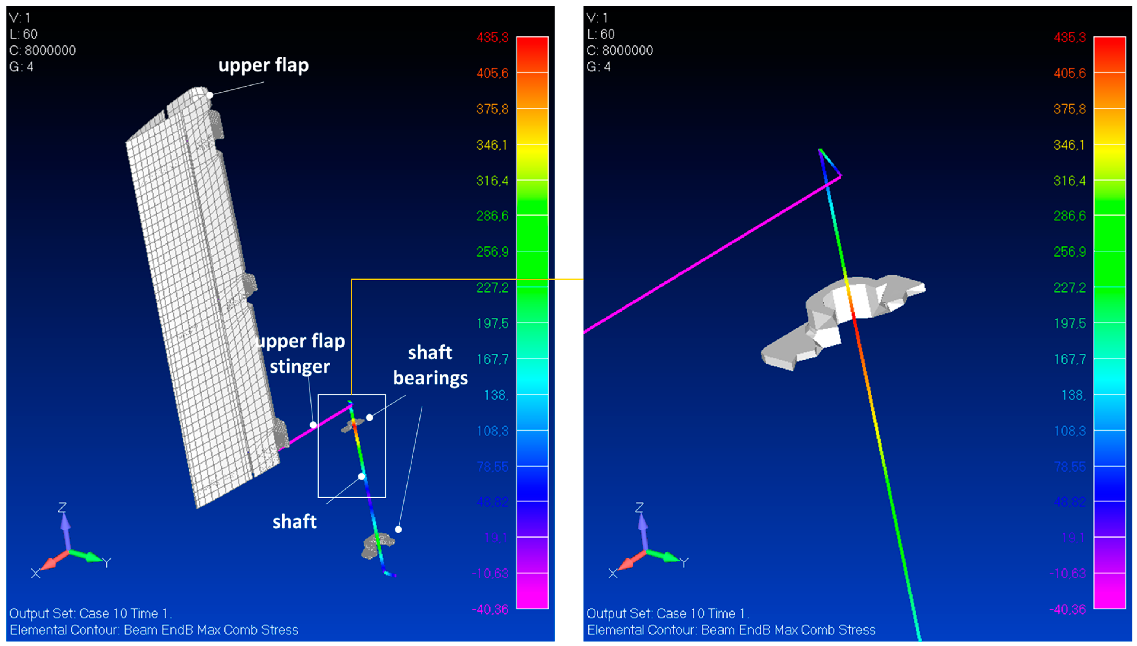
Another detail of the model of the architecture is shown in
Figure 10. Here the lower arm of the shaft and its connection with the actuator line is highlighted. The arm is welded to the shaft and normal to it. The connection to the actuator was obtained by overlapping the edge nodes of the two components and linking them with a rigid element. Also in this case a cylindric local reference system was used to handle the relative DOFs. The origin was fixed on the hinge, the
z axis was chosen normal to the plane containing the actuator line and the arm, the radial axis,
r, coincident to the arm direction and the remaining tangential axis,
t, normal to the others. In the same picture, the link between the shaft and the bearing is illustrated too. Also in this case, a spider rigid element was used to constraint some nodes of the bearing, enabling only rotations around the axis of the shaft. The same approach was also implemented for the upper arm of the shaft and for its connection to the upper flap stinger (the detail in
Figure 8 gives an idea of the layout).
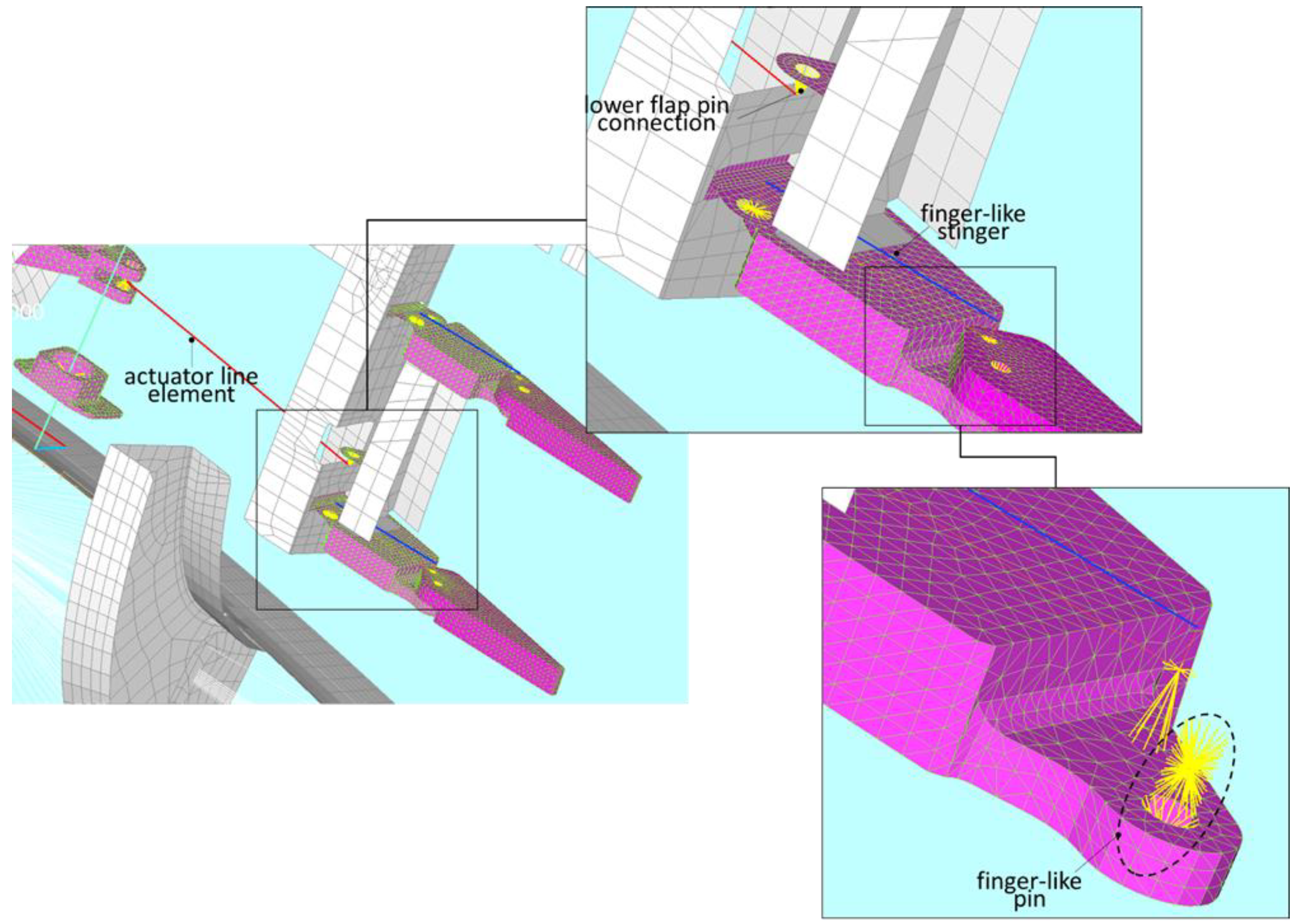
A spider element was used to connect the lower actuator to the flap. This element, as shown in the sketch on the top of
Figure 11, links the red actuator line to a flange, in turn connected to a spar of the lower surface. In the bottom sketch of the same figure also a detail of the joint between the rib pieces is illustrated. This connection was modelled through three rigid elements linked each other in serial way: two spiders collecting the nodes of the solid rib pieces and a rigid line between them, linking the centers of the spiders. Also the finger-like stinger element (see the blue line on the top scheme of
Figure 11) was connected to the rib pieces using spiders. For all the joints relevant to the finger-like mechanism, just the rotational DOF around the normal-to-rib plane were released. The same modelling approach was adopted for the upper flap kinematic chain. For sake of completeness, the main features of the model were collected in
Table 3.
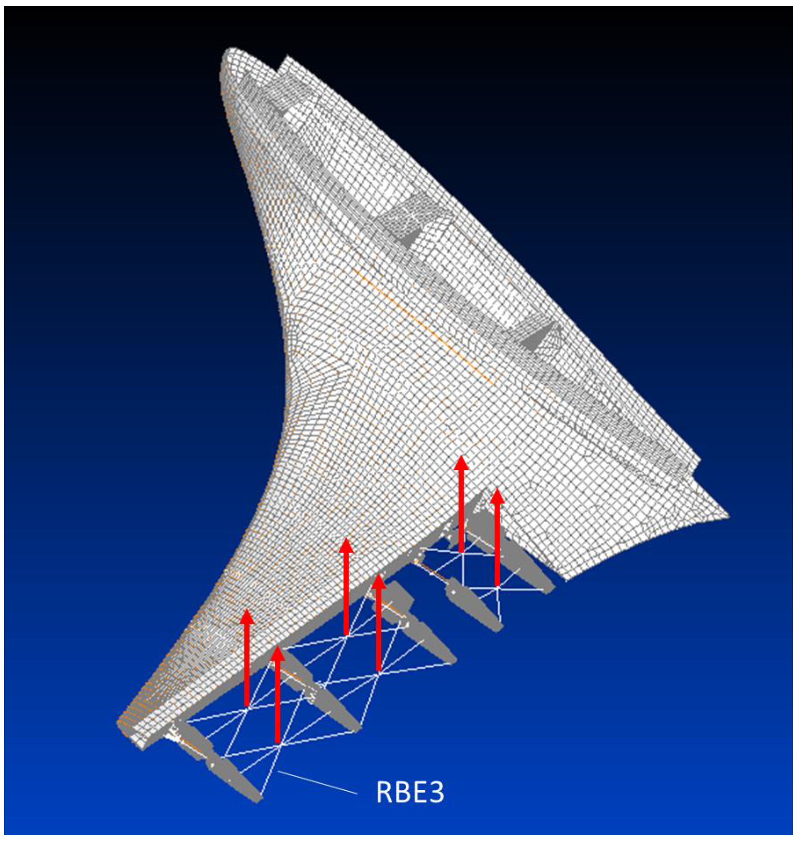
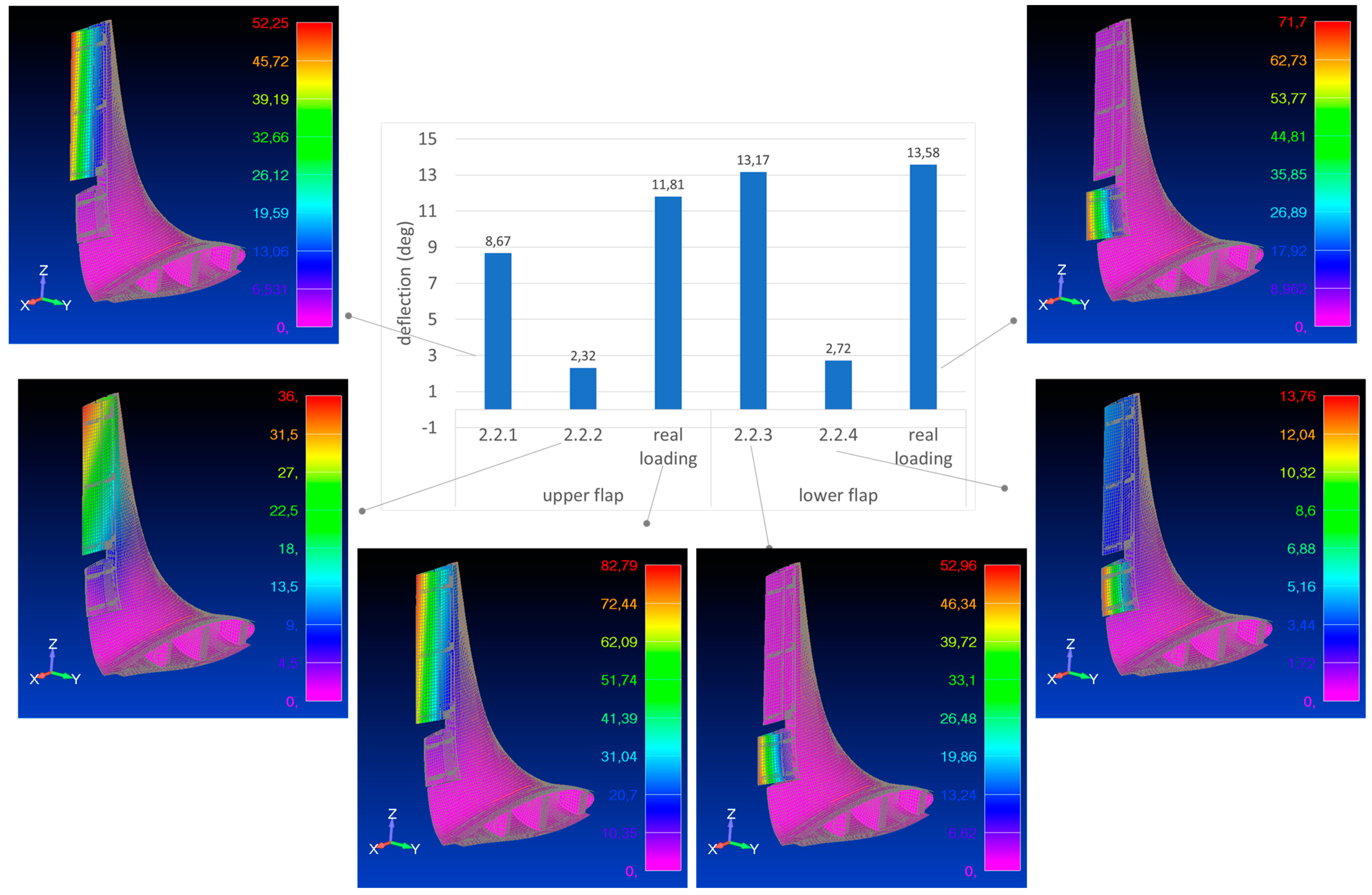
Another important aspect is represented by the loading strategy, that is to say, the approach adopted to apply the external loads, in compliance with the AWL working modality and with the tests. The loading architecture shown in
Figure 12 was implemented. In practice, spider nodes made of RBE3 rigid elements were used to transmit the loads to the rib of each box-shaped part of the movable surfaces. This type of rigid elements in fact, differently from the RBE2, do not alter the stiffness but distribute forces. Just one spider per each of the two box shaped parts of the lower flap was used, being its span extension really limited. For the upper flap, to better reproduce the variation of the load along the span direction, two rows of spiders were considered. Three types of load configurations were simulated. the corresponding distribution is summarized in
Table 4.
6. Critical Overview of the Results
The original morphing winglet specifications targeted a device able to reduce the root bending moment and increase the aerodynamic efficiency in off-design conditions, by unit percentages. Coherently with these requirements, it did result that its movables should have been deflected up to 15° outwards to attain the prescribed RBM reduction, while just 5° inwards resulted enough to increase the L/D by the designated figure. Such a deflection did apply for both the top and bottom surfaces, therefore moving in a synchronized way. This performance may be referred to climb and descent, mainly, while they do not apply for cruise flight, as the wing is optimized for that specific task. Nevertheless, the result was remarkable, and such to show the actual benefit of having a morphing surface on-board, acting to increase the degrees of freedom of the system. Its configuration, made of two separate movables, has solid bases in increasing the safety levels, for instance by leaving the capability of compensating possible faults of one by acting on the other, and in leaving open the room for future developments, as for gust alleviation needs, as an MDOF system has more potentiality to address the issue. Be clear that such further innovations shall pass through a devoted design, taking into consideration the dynamic response of the actuation network, and a proper assessment of the system inertia, in terms of both mass and momentum.
Concerning aeroelastic stability, it has been proved that there is a margin of a steady mass on the tip of about the 2.2% of the entire wing, before entering dangerous ranges of operations, and this ensures a certain leeway for future adjustments. Be clear that adding a further system to an existing wing it is not just matter of additional mass, as its dynamics may deeply influence the whole response (f.i., as in the case of the well-known dynamic vibration absorbers, or DVA). On the other side, there are certain features that deserve a certain attention in the case of the exploitation of that architecture towards other objectives. Specifically, the bottom segment (lower multi-tab) exhibits a relatively low torsional stiffness (41.9 N/° ≅ 650 Nm/rad), which is not so far away the minimum allowed values established by the simulations. This issue does not apply, instead, for the top segment. In synthesis, it can be stated that the designed system well-matched the original requirements, furthermore providing interesting possibilities for further developments.
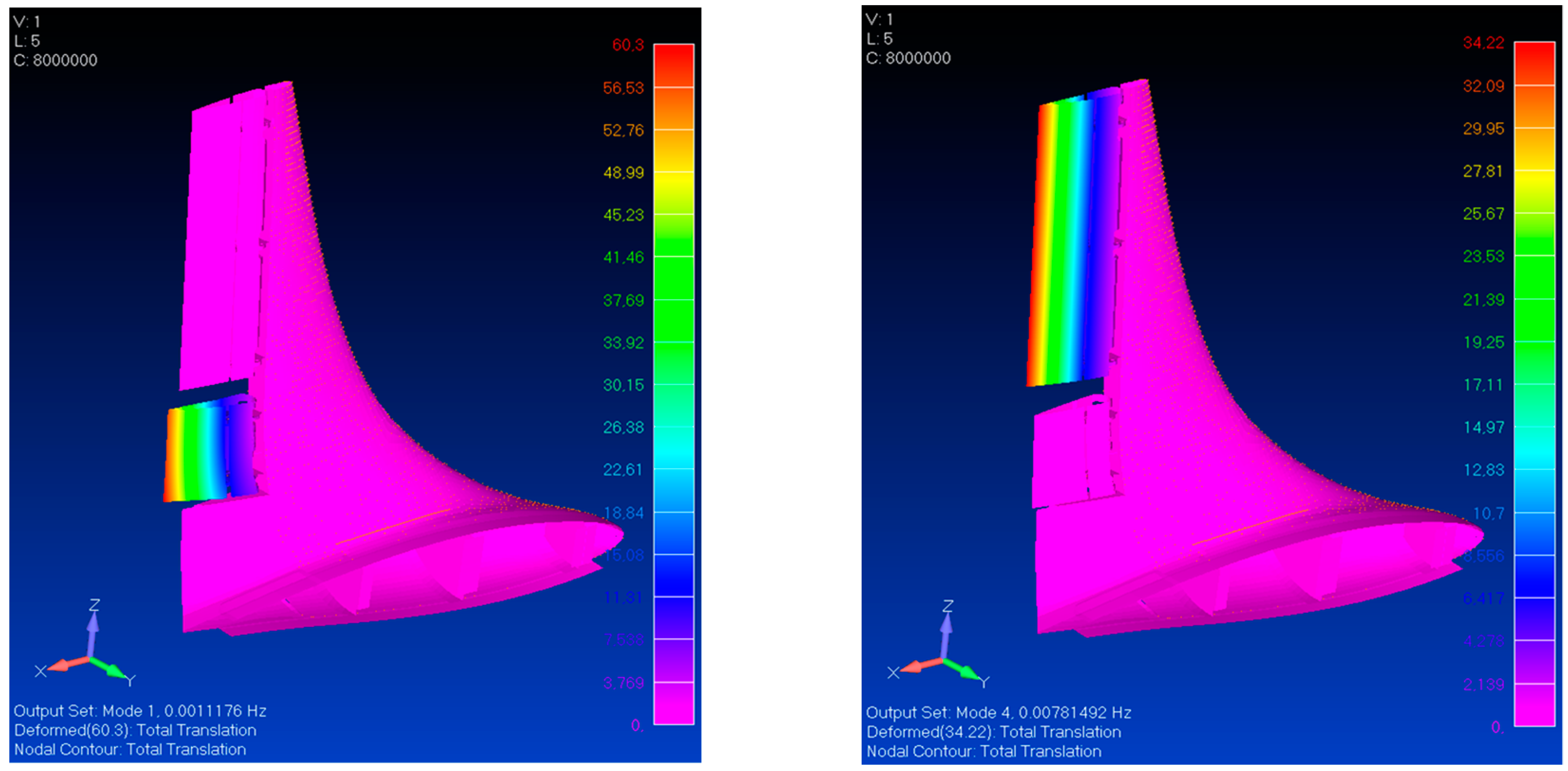
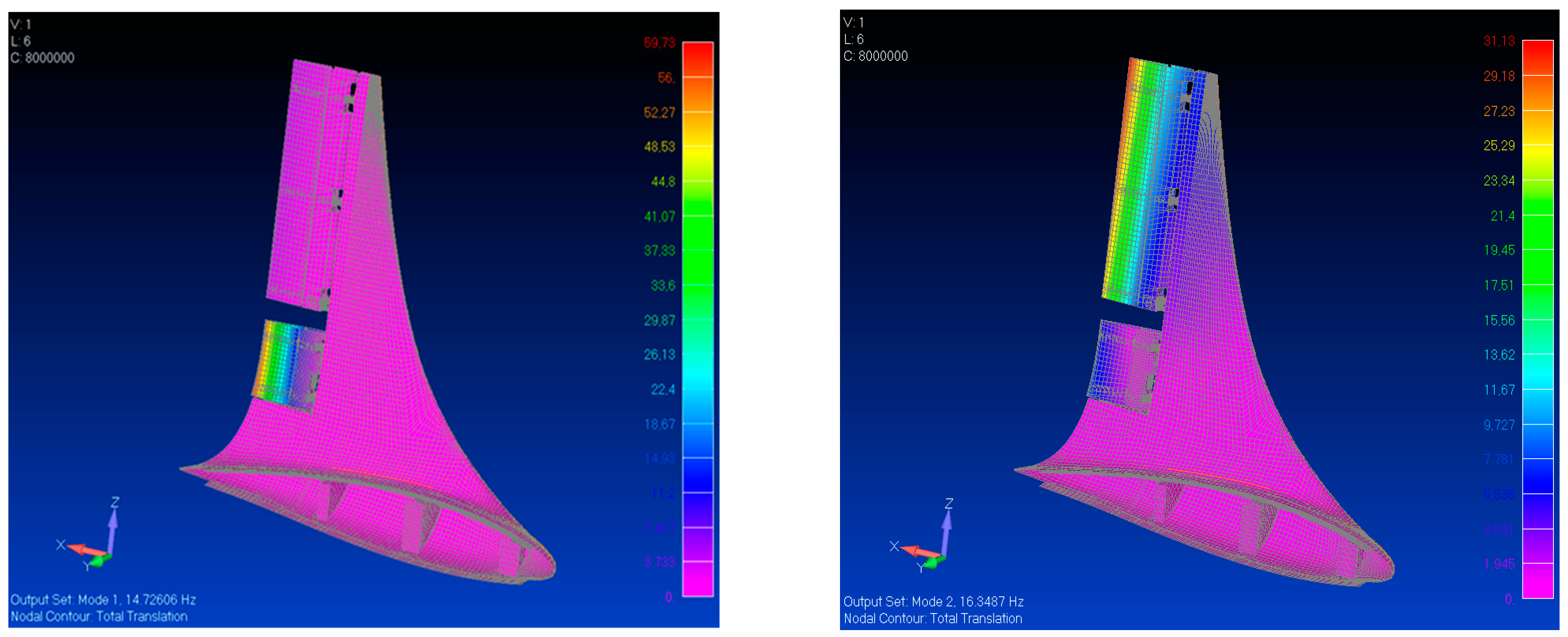
Going to the main aim of the present paper, it can be stated that the model of the kinematic chain proved to be an excellent tool for verifying the performance of the designed system, and pointing out at possible improvements for the increase of its safety margins, or even its working capability. Such a model was fundamental to appraise the system behavior well ahead of the ground experimentation, and the foreseen flight tests. Among the other things, it was possible to have hints about the expected variations of the operating envelope as the system should undergo operation loads, as the kinematic chain would have suffered some limitations. Such predictions were widely confirmed by the outcomes of the lab investigations. These static studies were then complemented by modal analyses, which allowed confirming the goodness of the model itself by verifying the existence of the so-called rigid modes (expression of the system labilities as the actuator presence, and its stiffness, was removed), and by acquiring important information about the effects of the mass and stiffness distributions (in the conditions with and without actuator systems).
On the basis of the numerical predictions on the movable parts and on the fixed structure of the AWL, a prototype was built. The deflections of the movable parts were measured. In
Table 7, the experimental data obtained loading the tabs of the upper and lower flaps were compared with the corresponding numerical predictions. The observed maximum deviation of about 10% was ascribed to factors not considered in the numerical modelling, as free-play and gap angles existing among the kinematic components of the real structure.
Future developments will consider the possibility of closing the space gap between actuators and movables, taking advantage of the technological developments which are expected to provide lighter and more powerful devices. Such an innovation will have a dramatic impact on the system compactness, and in turn, on the mass and stiffness distribution. In the same way, exploitation of the proposed architecture to other applications and configurations will be investigated, both on aircraft and other means of transportation (automotive, naval, and so on).
7. Conclusions and Future Steps
In this work the modelling of the movable parts of an adaptive winglet, AWL, was illustrated. The AWL was conceived to guarantee specific functionalities oriented to: (1) cover off-design conditions; (2) improve the performance the wing at specific flight segments (climb); (3) redistribute the external loads along the span to mitigate the level of solicitation of the wing. The two movable surfaces the AWL is equipped with, guarantee all mentioned functionalities through smooth and independent inward and outward deflections. This effect is obtained by means of dedicated kinematic chains transmitting the linear motion of the actuators hosted in the fixed part of the winglet to the surfaces in turns split into different subparts driven by finger-like mechanisms.
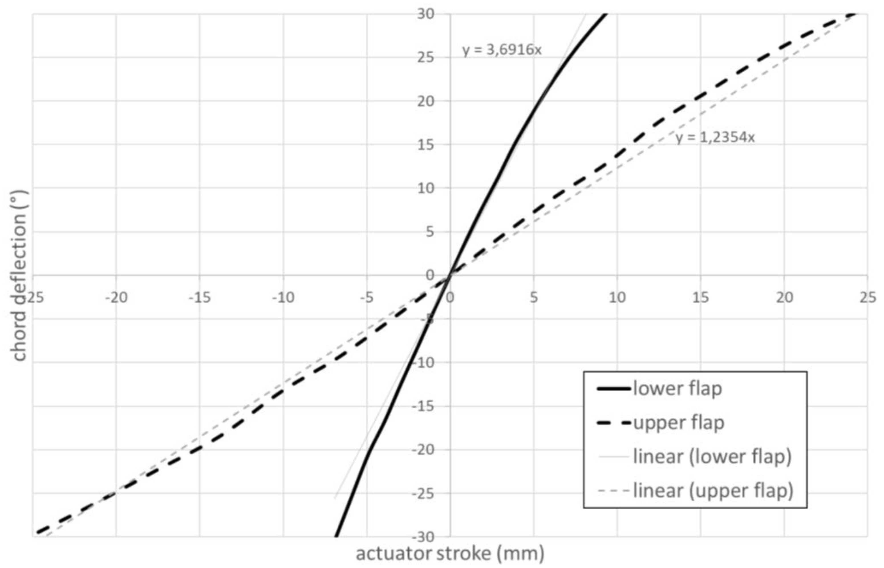
The AWL specific configuration and working modality, envisaging large deflections of the movable parts driven by finger-like mechanisms, led to the use of a specific modelling approach, able to catch the non-linearities of the system. To this scope, the non-linear solver SOL 400 of the MSC/Nastran software was used. The different parts of the kinematic chains were modelled through beam-like finite elements. Particular attention was paid to their connection for its impact on the relative motion. The hinges were represented by means of rigid elements, releasing the DOFs corresponding to the free components. Due to the sensitivity of this operation, two checks were performed: a normal mode analysis disconnecting the actuators and a stress analysis expanding/contracting the actuators without applying any external loads. The low frequencies and stress levels obtained confirmed the consistency of the model for simulating the functionality of the flaps. After this step, the simulation was addressed, relating the angular deflection in outward and inward directions of both the surfaces with the strokes of the actuators. The analysis highlighted the different rigidity of the two kinematic chains, then confirmed by the application of the external loads. The investigation of the impact of the external loads was addressed considering specific load distributions, strictly related to the ground tests specifications and to the realistic application of the loads. The outcomes highlighted remarkable deflections in any case recoverable with the actuation system and not producing critical stress levels.
The simulations herein presented showed the capability of the movable parts to achieve and potentially overshoot the prescribed deflections (from −15° to +5°), in this sense supporting the abovementioned functionality expectations, even in presence of very severe loading conditions. These results, jointly to other verifications addressed on the fixed part of the winglet, paved the way to the realization of a prototype for ground validations that confirmed the numerical predictions. Still in line with the maturation path foreseen in AIRGREEN2, a left and right version of the winglet were also manufactured for flight tests scheduled at June 2023.


 ,
, 


