
Learning-Based Visual Servoing for High-Precision Peg-in-Hole Assembly

Abstract
:1. Introduction
- (1)
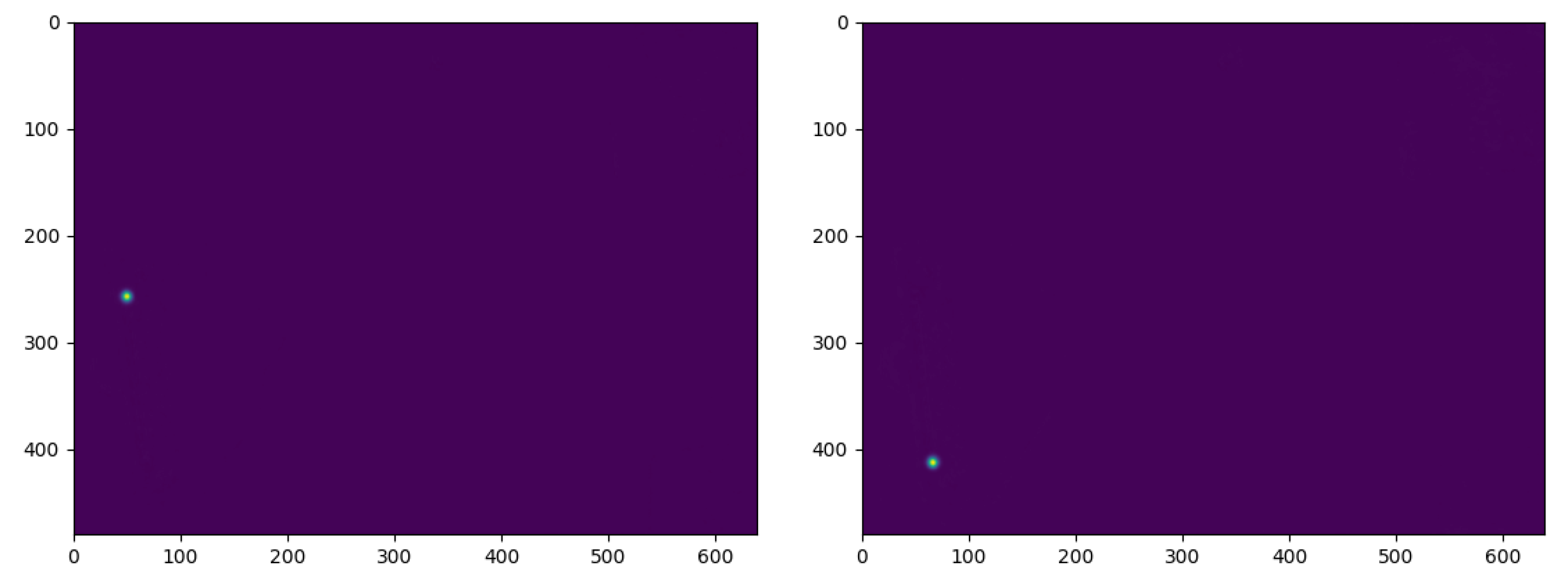
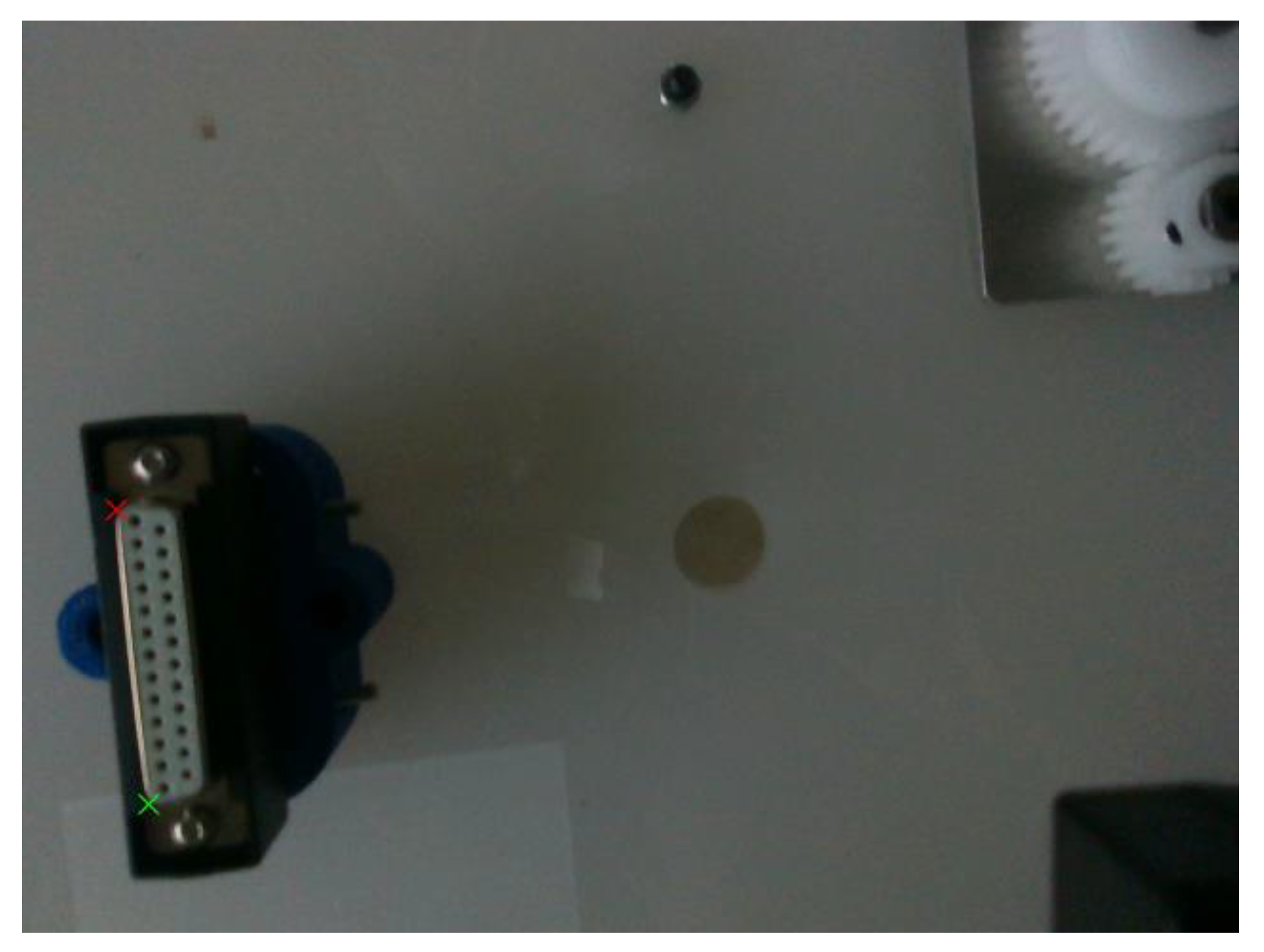
- A neural network for workpiece landmark estimation is proposed, which can extract specific features from an image.
- (2)
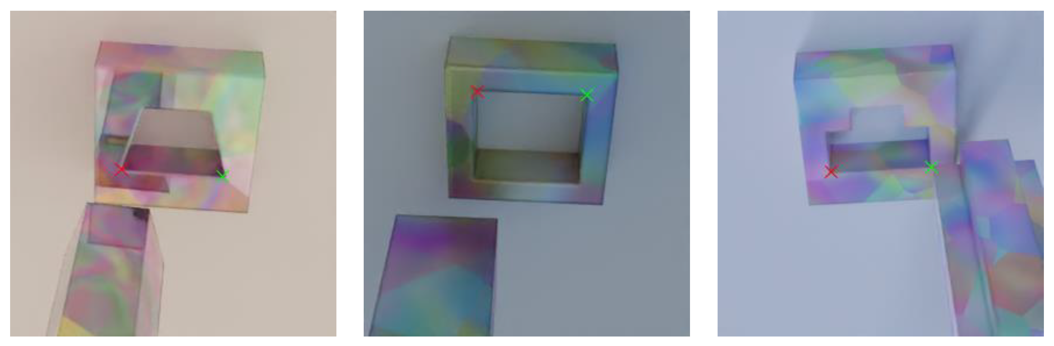
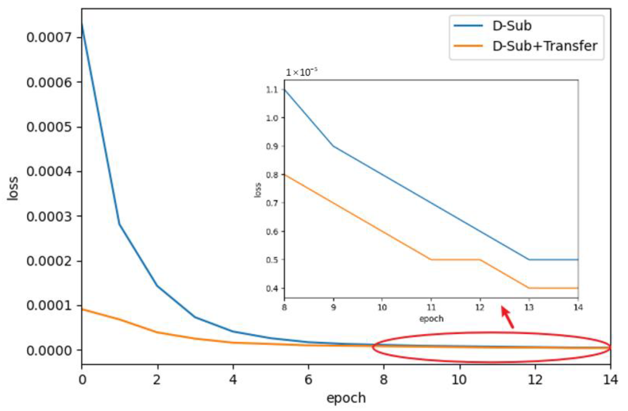
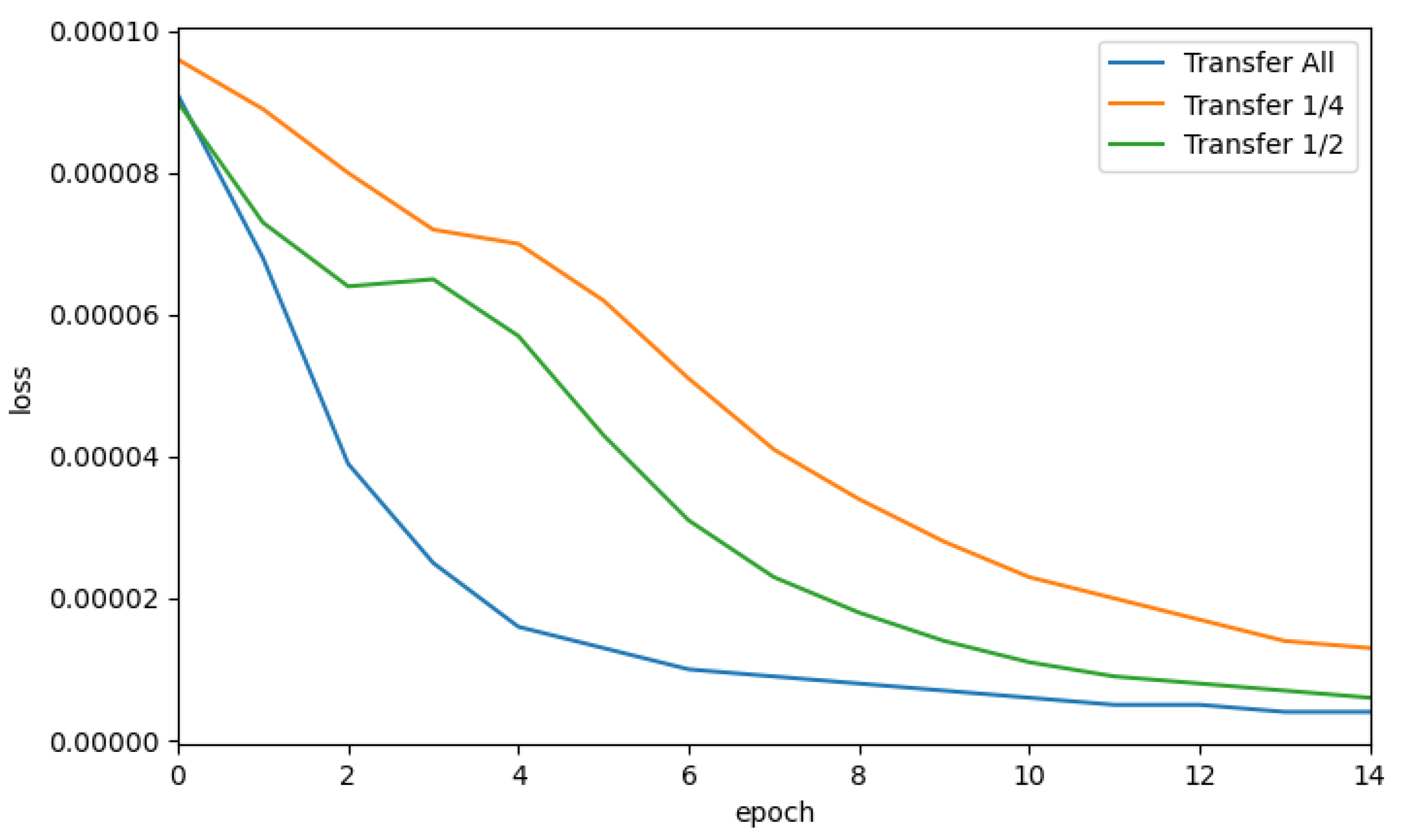
- A synthetic data generation method for peg-in-hole assembly is presented to achieve transfer learning for real-world assembly.
- (3)
- A multi-modal peg-in-hole strategy is designed to combine learning-based visual servoing and force control.
- (4)
- The results in real peg-in-hole experiments show that the proposed method has a higher success rate and efficiency compared to the baseline method.
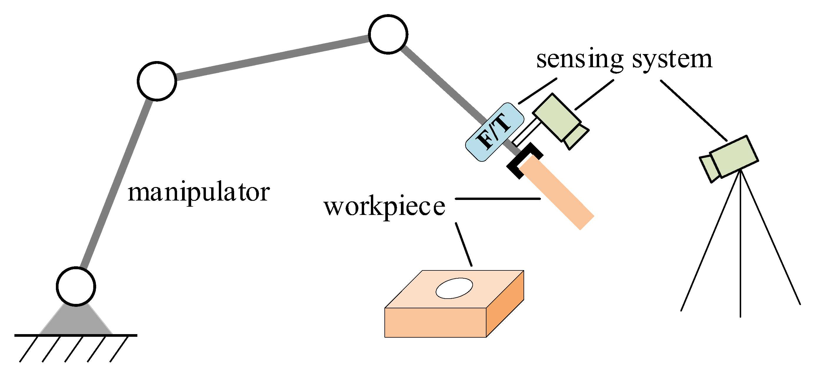
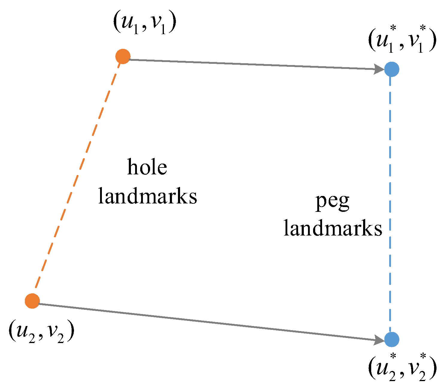
2. Problem Setup
3. Method
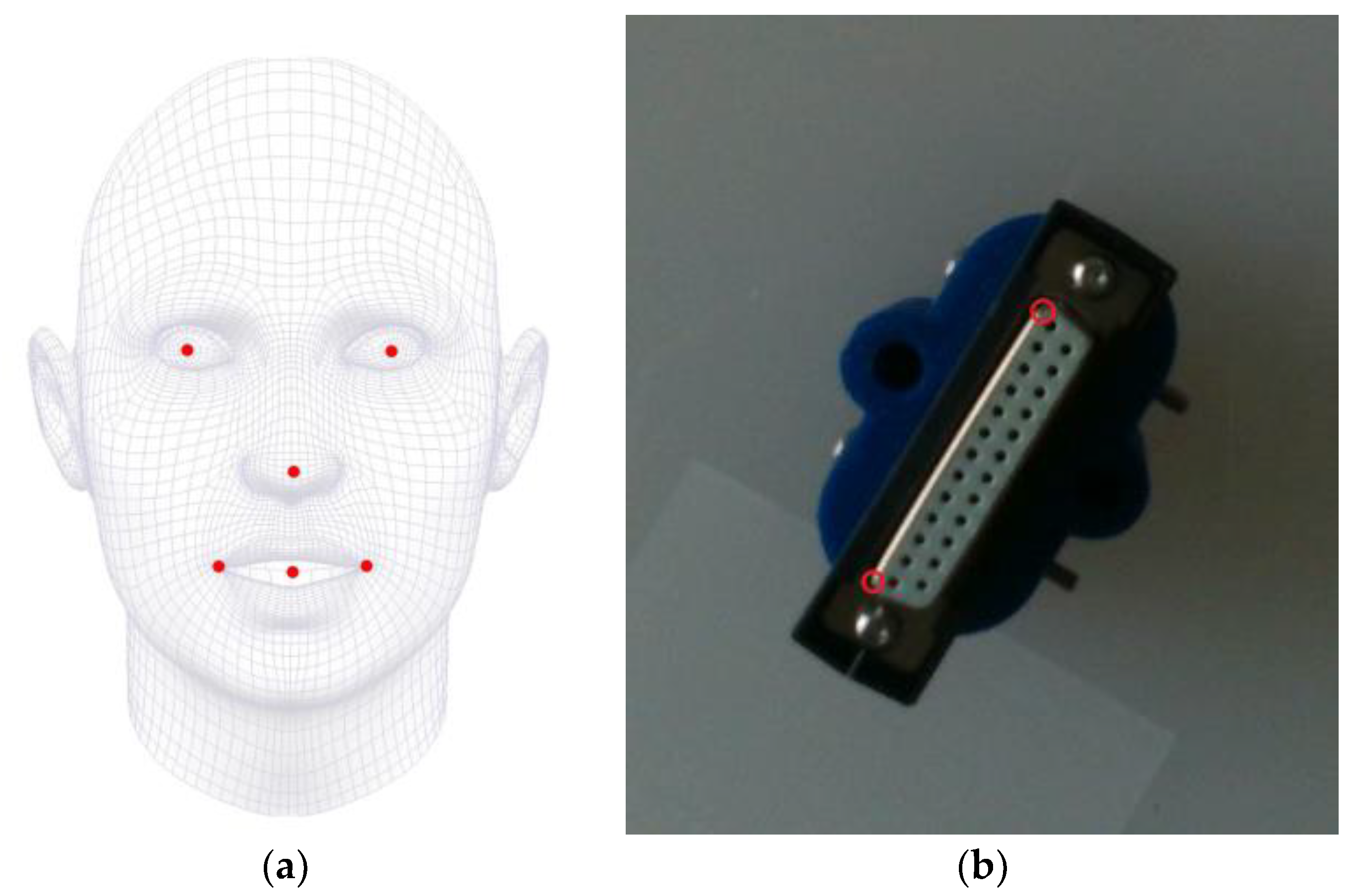
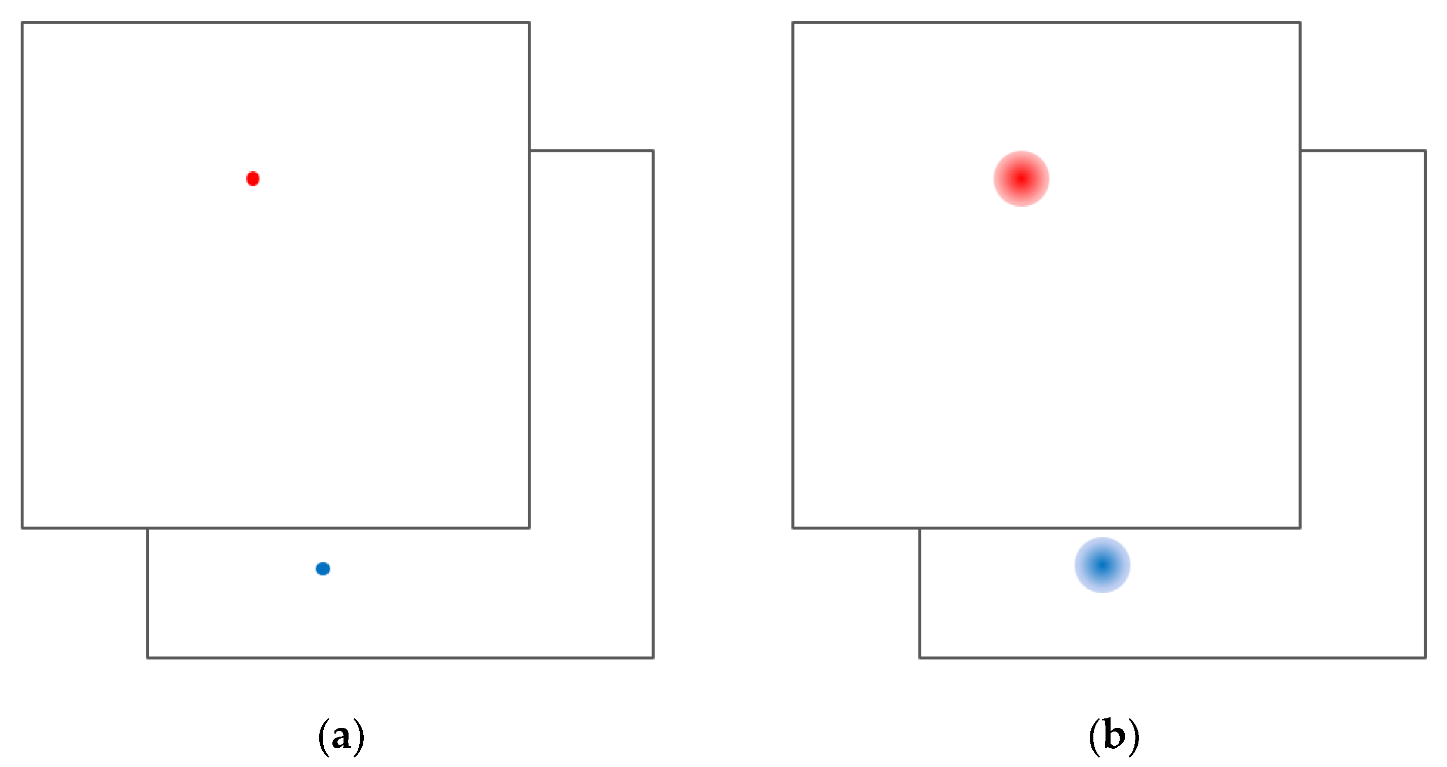
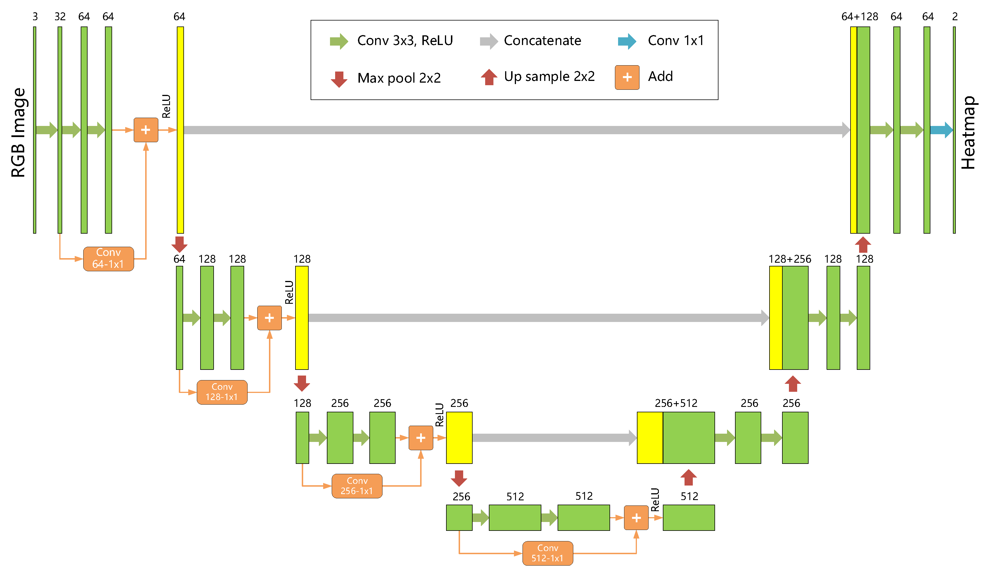
3.1. P2HNet
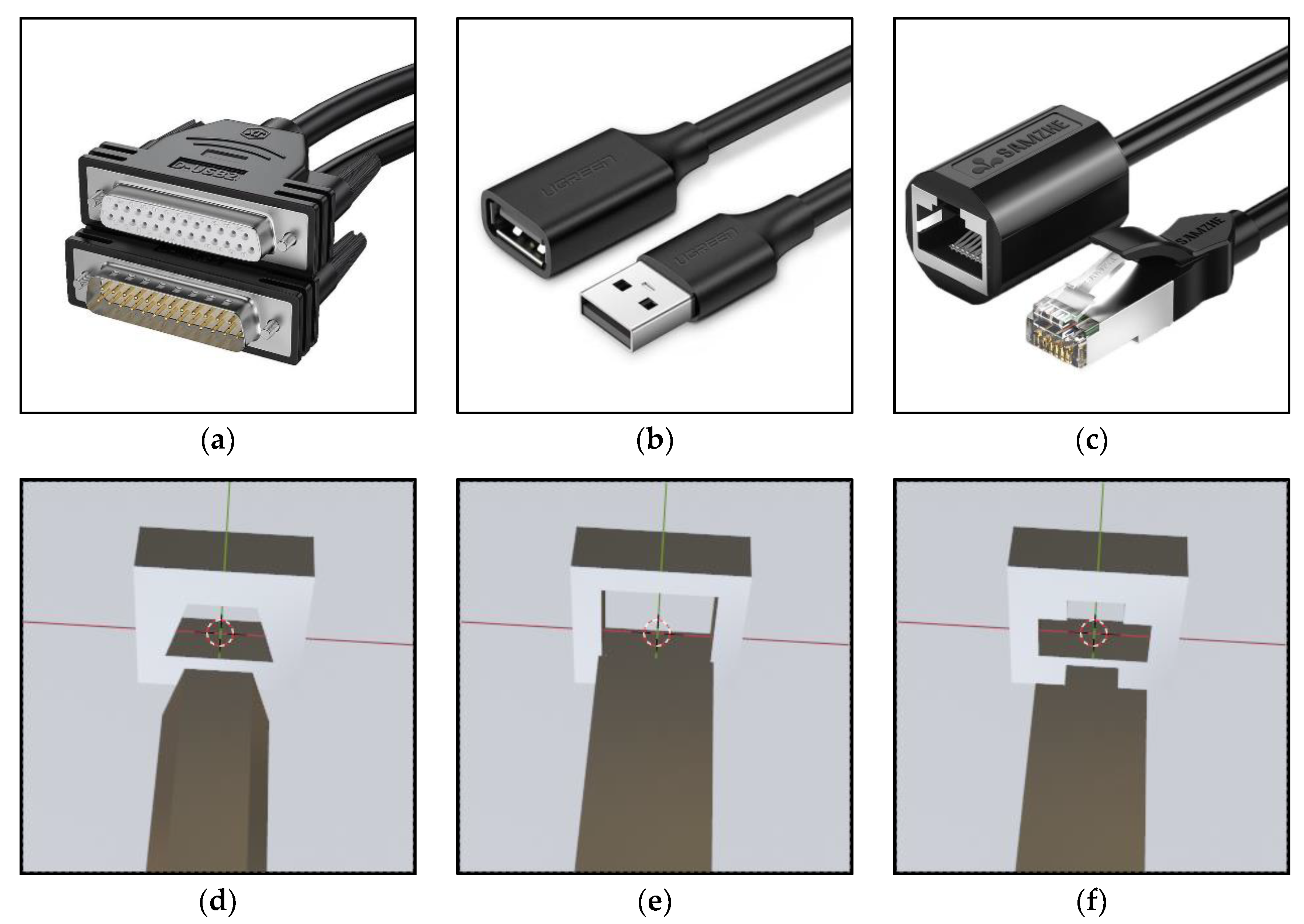
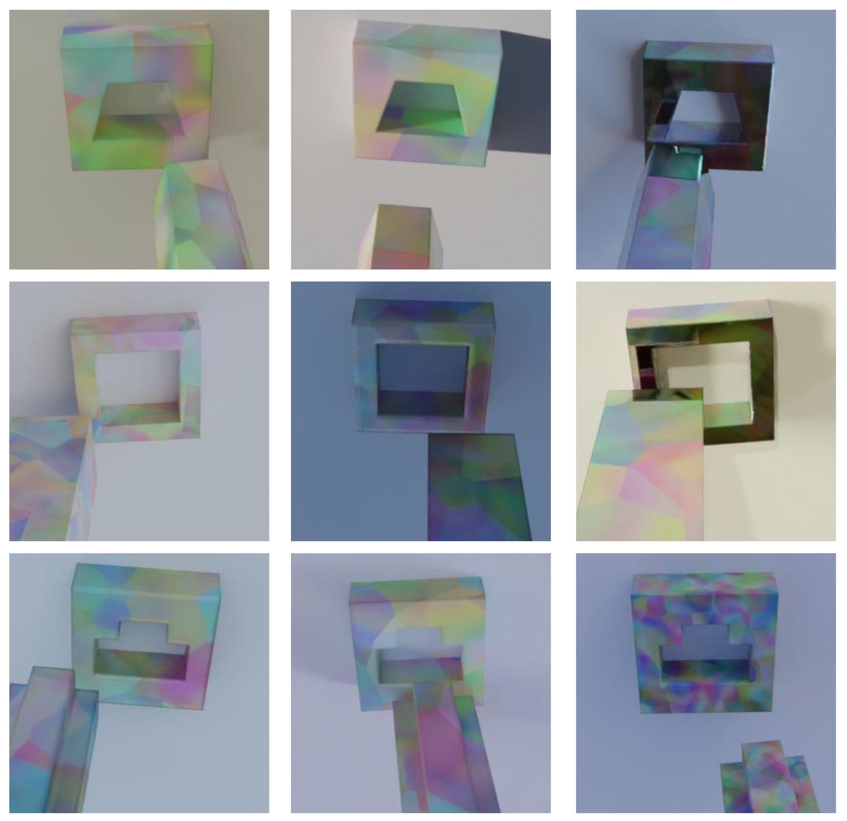
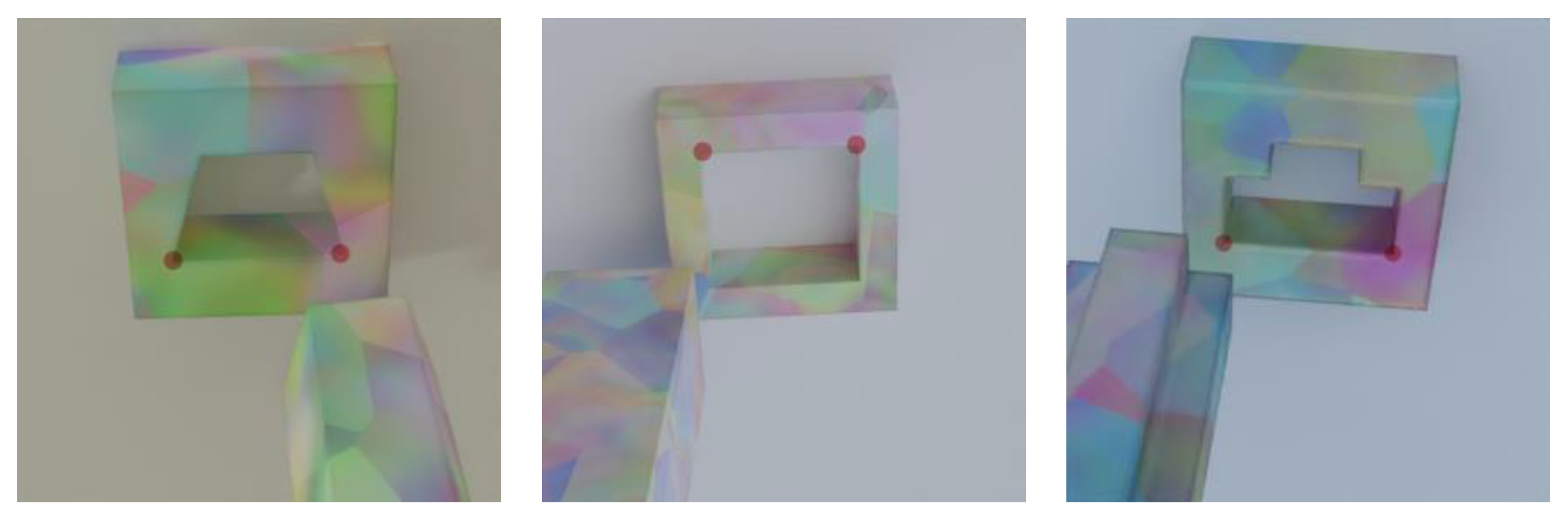
3.2. Synthetic Data Generation
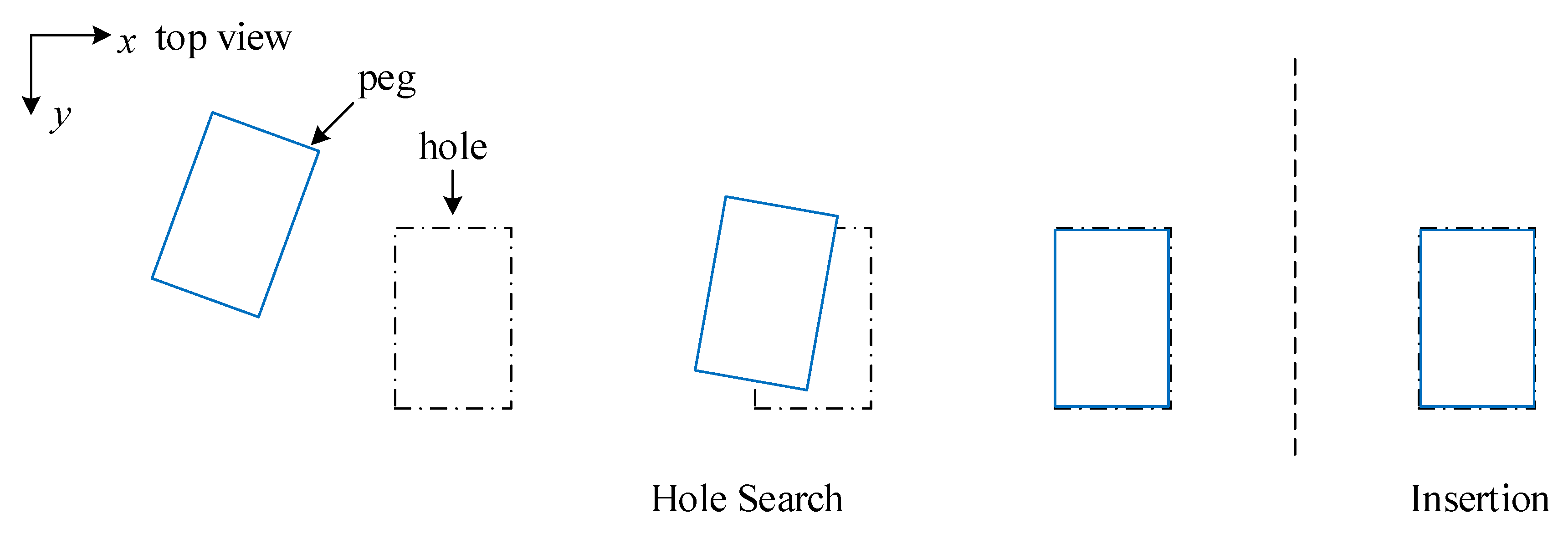
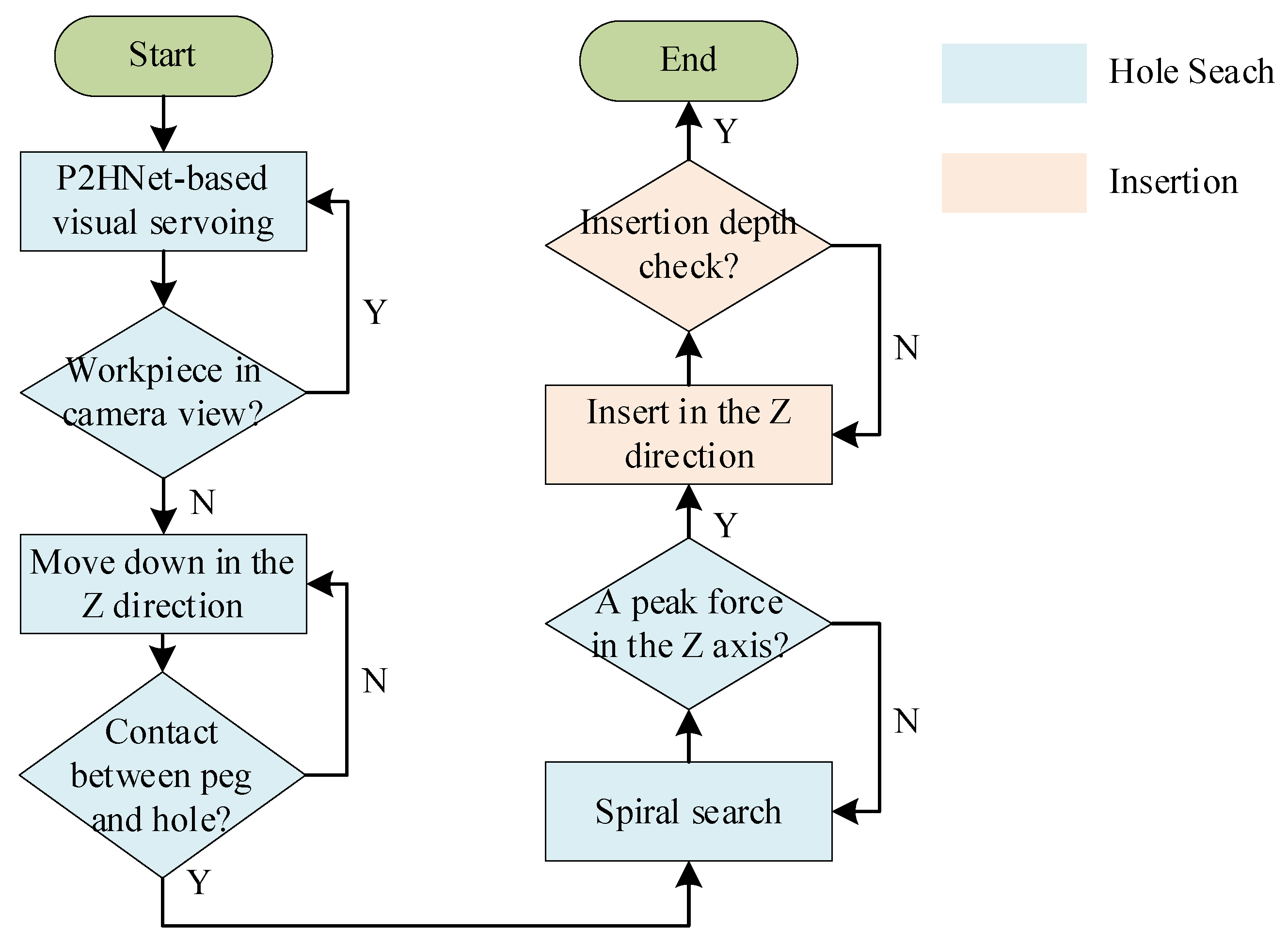
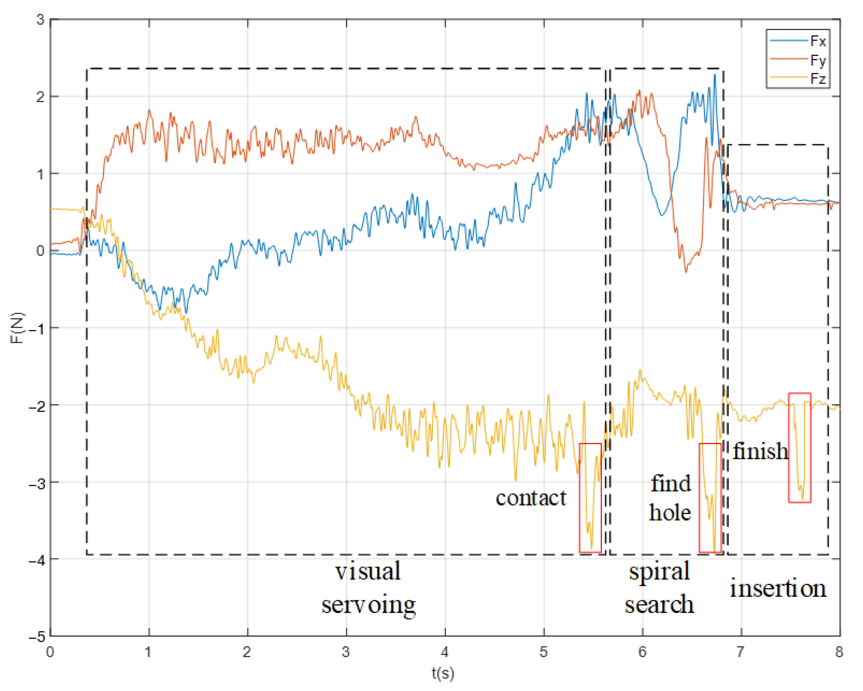
3.3. Multi-Modal Peg-in-Hole Strategy
4. Experiment
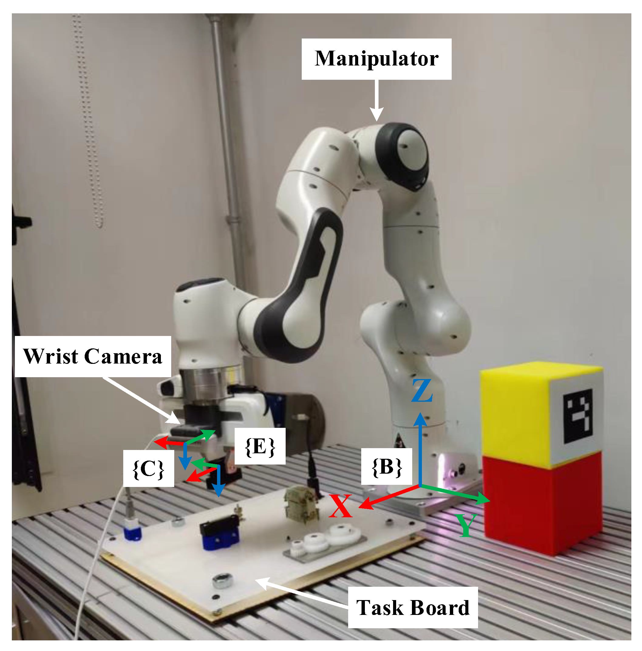
4.1. Experiment Setup
4.2. Evaluation of P2HNet
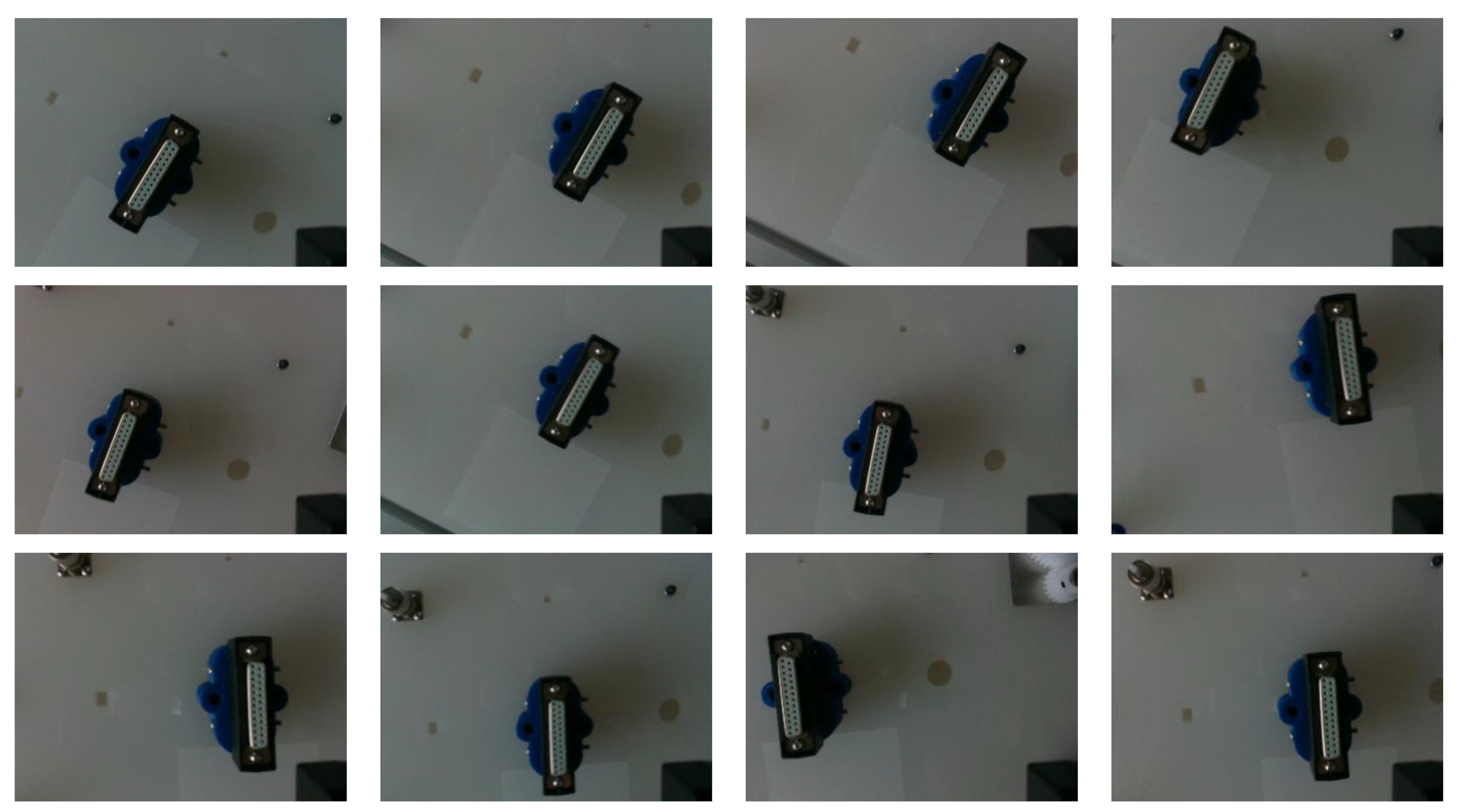
4.2.1. Dataset
4.2.2. Train and Test
4.3. Peg-in-Hole Experiment
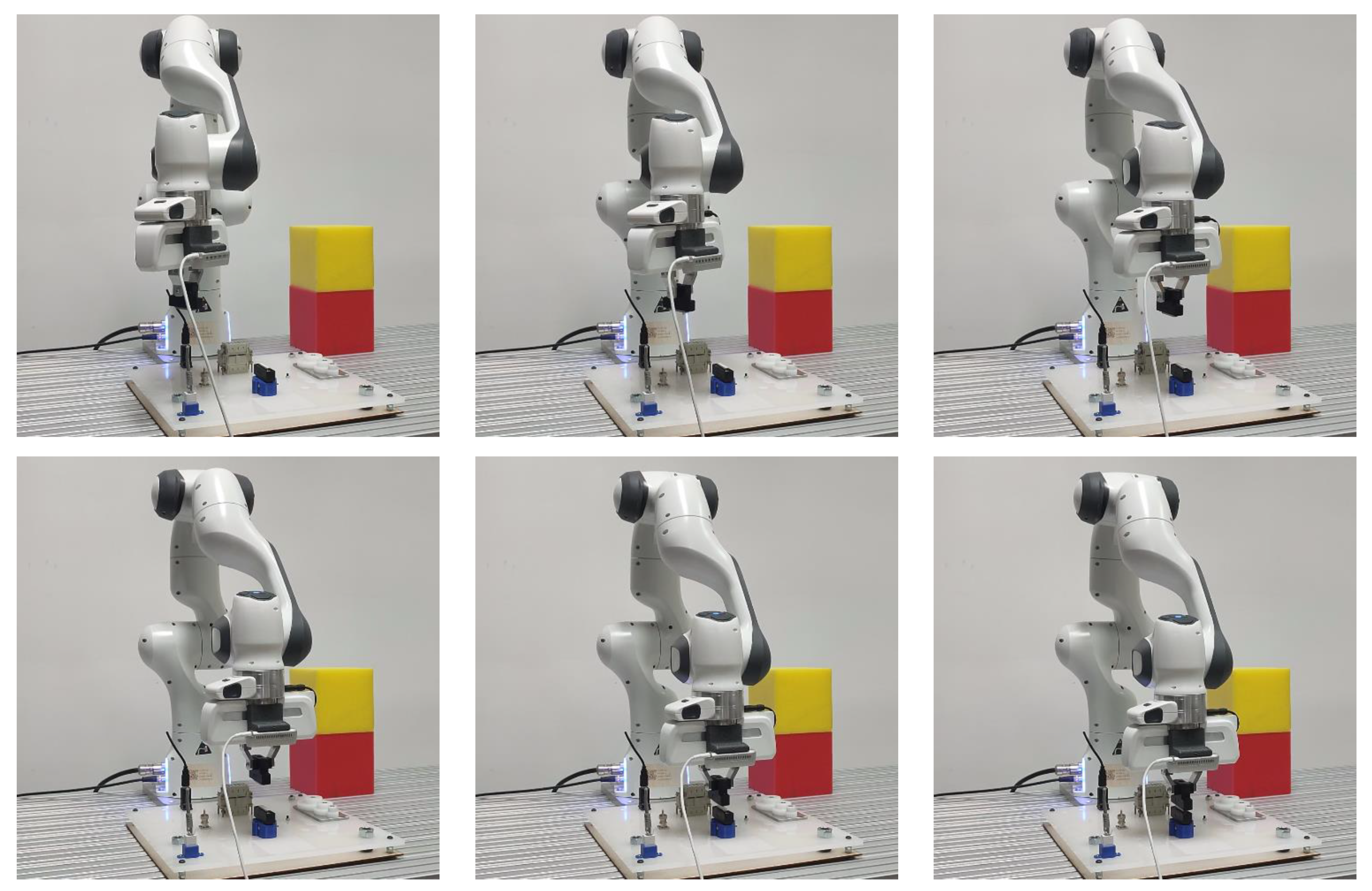
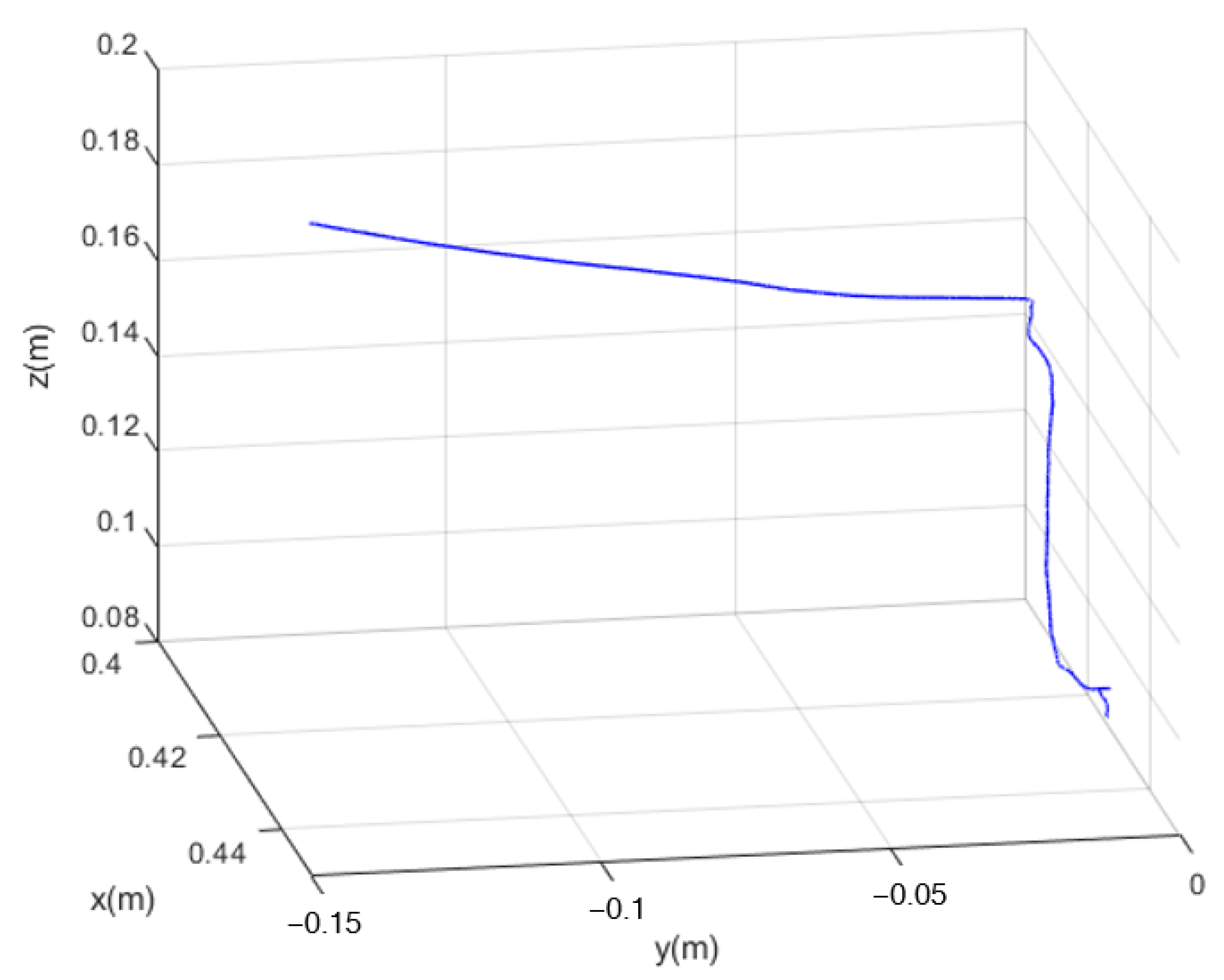
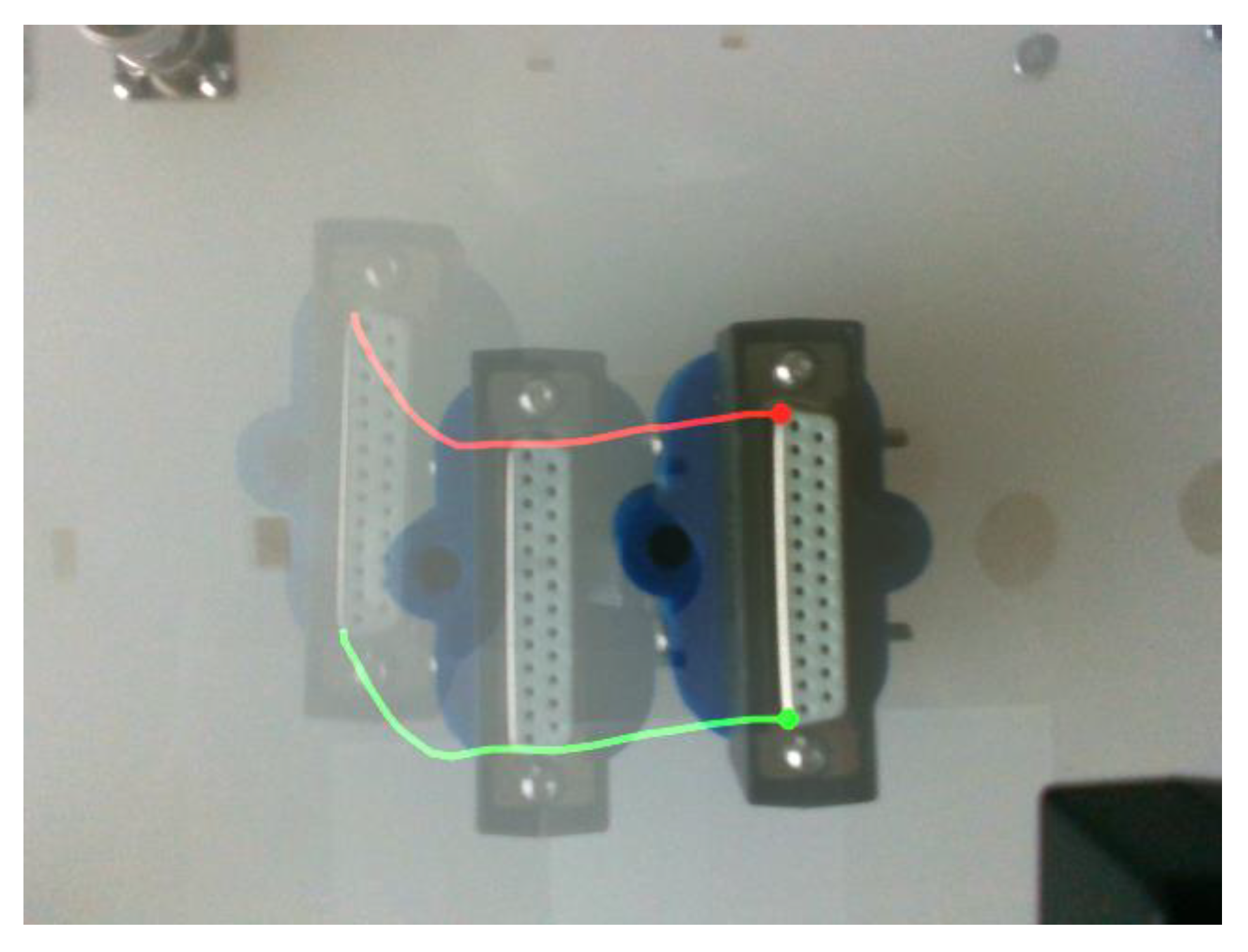
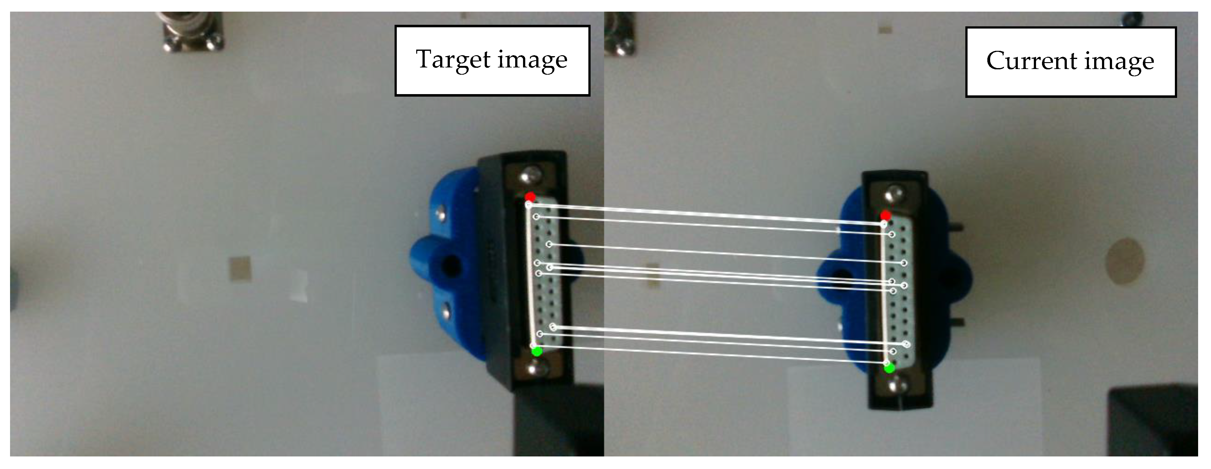
4.3.1. P2HNet-Based Visual Servo for Assembly
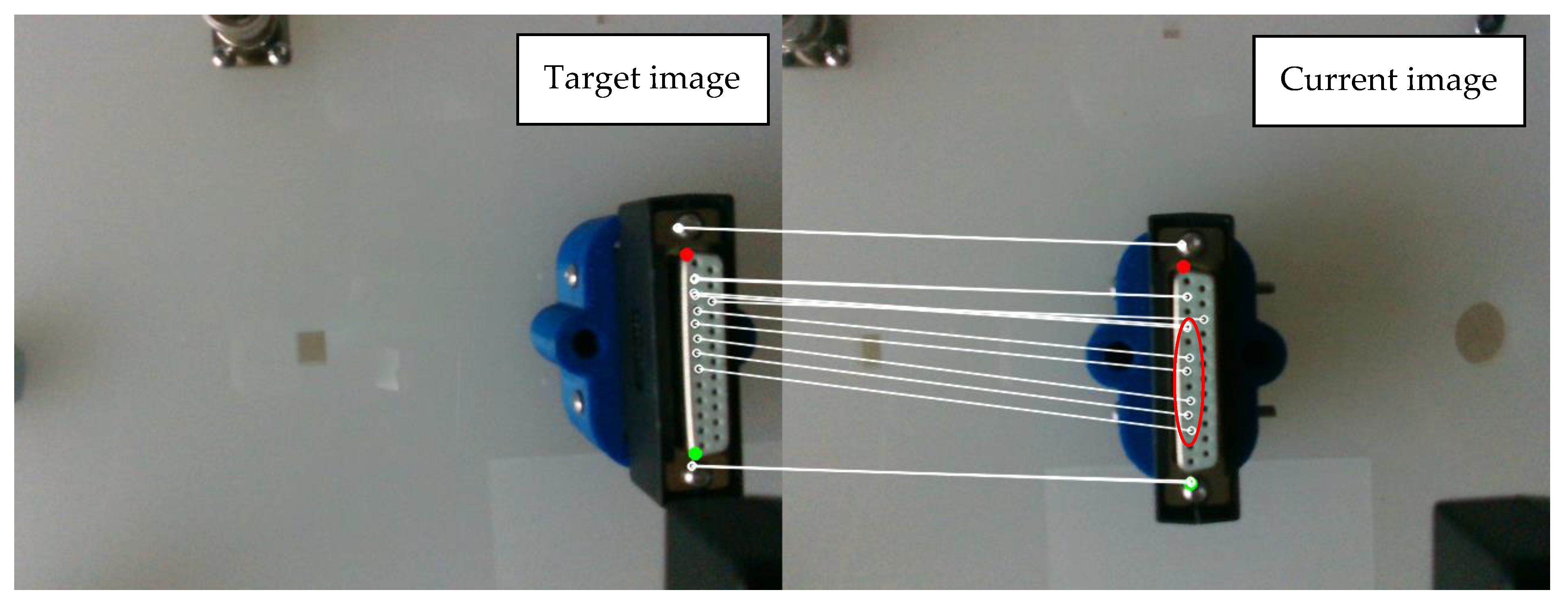
4.3.2. Method Comparison
5. Conclusions
Author Contributions
Funding
Institutional Review Board Statement
Informed Consent Statement
Data Availability Statement
Conflicts of Interest
References
- Mei, B.; Zhu, W. Accurate Positioning of a Drilling and Riveting Cell for Aircraft Assembly. Robot. Comput.-Integr. Manuf. 2021, 69, 102112. [Google Scholar] [CrossRef]
- Hebecker, M.; Lambrecht, J.; Schmitz, M. Towards Real-World Force-Sensitive Robotic Assembly through Deep Reinforcement Learning in Simulations. In Proceedings of the 2021 IEEE/ASME International Conference on Advanced Intelligent Mechatronics (AIM), Delft, The Netherlands, 12–16 July 2021; pp. 1045–1051. [Google Scholar]
- Haugaard, R.L.; Glent Buch, A.; Iversen, T.M. Self-Supervised Deep Visual Servoing for High Precision Peg-in-Hole Insertion. In Proceedings of the 2022 IEEE 18th International Conference on Automation Science and Engineering (CASE), Mexico City, Mexico, 22–26 August 2022; pp. 405–410. [Google Scholar]
- Jiang, J.; Yao, L.; Huang, Z.; Yu, G.; Wang, L.; Bi, Z. The State of the Art of Search Strategies in Robotic Assembly. J. Ind. Inf. Integr. 2022, 26, 100259. [Google Scholar] [CrossRef]
- Chaumette, F.; Hutchinson, S. Visual Servo Control. I. Basic Approaches. IEEE Robot. Autom. Mag. 2006, 13, 82–90. [Google Scholar] [CrossRef]
- Park, H.; Park, J.; Lee, D.-H.; Park, J.-H.; Baeg, M.-H.; Bae, J.-H. Compliance-Based Robotic Peg-in-Hole Assembly Strategy Without Force Feedback. IEEE Trans. Ind. Electron. 2017, 64, 6299–6309. [Google Scholar] [CrossRef]
- Chang, W.-C. Robotic Assembly of Smartphone Back Shells with Eye-in-Hand Visual Servoing. Robot. Comput.-Integr. Manuf. 2018, 50, 102–113. [Google Scholar] [CrossRef]
- Wang, R.; Liang, C.; Pan, D.; Zhang, X.; Xin, P.; Du, X. Research on a Visual Servo Method of a Manipulator Based on Velocity Feedforward. Space Sci. Technol. 2021, 2021, 9763179. [Google Scholar] [CrossRef]
- Niu, X.; Pu, J.; Zhang, C. An Improved SIFT Algorithm for Monocular Vision Positioning. IOP Conf. Ser. Mater. Sci. Eng. 2019, 612, 032124. [Google Scholar] [CrossRef]
- Ding, G.; Liu, Y.; Zang, X.; Zhang, X.; Liu, G.; Zhao, J. A Task-Learning Strategy for Robotic Assembly Tasks from Human Demonstrations. Sensors 2020, 20, 5505. [Google Scholar] [CrossRef] [PubMed]
- Kang, H.; Zang, Y.; Wang, X.; Chen, Y. Uncertainty-Driven Spiral Trajectory for Robotic Peg-in-Hole Assembly. IEEE Robot. Autom. Lett. 2022, 7, 6661–6668. [Google Scholar] [CrossRef]
- Gu, J.; Zhu, M.; Cao, L.; Li, A.; Wang, W.; Xu, Z. Improved Uncalibrated Visual Servo Strategy for Hyper-Redundant Manipulators in On-Orbit Automatic Assembly. Appl. Sci. 2020, 10, 6968. [Google Scholar] [CrossRef]
- Zou, P.; Zhu, Q.; Wu, J.; Xiong, R. Learning-Based Optimization Algorithms Combining Force Control Strategies for Peg-in-Hole Assembly. In Proceedings of the 2020 IEEE/RSJ International Conference on Intelligent Robots and Systems (IROS), Las Vegas, NV, USA, 25–29 October 2020; pp. 7403–7410. [Google Scholar]
- Spector, O.; Zacksenhouse, M. Learning Contact-Rich Assembly Skills Using Residual Admittance Policy. In Proceedings of the 2021 IEEE/RSJ International Conference on Intelligent Robots and Systems (IROS), Prague, Czech Republic, 23–27 September 2021; pp. 6023–6030. [Google Scholar]
- Triyonoputro, J.C.; Wan, W.; Harada, K. Quickly Inserting Pegs into Uncertain Holes Using Multi-View Images and Deep Network Trained on Synthetic Data. In Proceedings of the 2019 IEEE/RSJ International Conference on Intelligent Robots and Systems (IROS), Macao, China, 4–8 November 2019; pp. 5792–5799. [Google Scholar]
- Haugaard, R.L.; Sloth, C.; Langaa, J. Fast Robust Peg-in-Hole Insertion with Continuous Visual Servoing. In Proceedings of the CoRL, Cambridge, MA, USA, 16–18 November 2020; p. 10. [Google Scholar]
- Puang, E.Y.; Peng Tee, K.; Jing, W. KOVIS: Keypoint-Based Visual Servoing with Zero-Shot Sim-to-Real Transfer for Robotics Manipulation. In Proceedings of the 2020 IEEE/RSJ International Conference on Intelligent Robots and Systems (IROS), Las Vegas, NV, USA, 25–29 October 2020; pp. 7527–7533. [Google Scholar]
- Spector, O.; Castro, D.D. InsertionNet-A Scalable Solution for Insertion. IEEE Robot. Autom. Lett. 2021, 6, 5509–5516. [Google Scholar] [CrossRef]
- Spector, O.; Tchuiev, V.; Di Castro, D. InsertionNet 2.0: Minimal Contact Multi-Step Insertion Using Multimodal Multiview Sensory Input. In Proceedings of the 2022 International Conference on Robotics and Automation (ICRA), Philadelphia, PA, USA, 23–27 May 2022; pp. 6330–6336. [Google Scholar]
- Xie, L.; Yu, H.; Zhao, Y.; Zhang, H.; Zhou, Z.; Wang, M.; Wang, Y.; Xiong, R. Learning to Fill the Seam by Vision: Sub-Millimeter Peg-in-Hole on Unseen Shapes in Real World. In Proceedings of the 2022 International Conference on Robotics and Automation (ICRA), Philadelphia, PA, USA, 23–27 May 2022; pp. 2982–2988. [Google Scholar]
- Zhu, X.; Ramanan, D. Face Detection, Pose Estimation, and Landmark Localization in the Wild. In Proceedings of the 2012 IEEE Conference on Computer Vision and Pattern Recognition, Providence, RI, USA, 16–21 June 2012; pp. 2879–2886. [Google Scholar]
- Sun, K.; Xiao, B.; Liu, D.; Wang, J. Deep High-Resolution Representation Learning for Human Pose Estimation. In Proceedings of the IEEE/CVF conference on computer vision and pattern recognition 2019, Long Beach, CA, USA, 15–19 June 2019; pp. 5693–5703. [Google Scholar]
- Ronneberger, O.; Fischer, P.; Brox, T. U-Net: Convolutional Networks for Biomedical Image Segmentation. In Medical Image Computing and Computer-Assisted Intervention–MICCAI 2015; Navab, N., Hornegger, J., Wells, W.M., Frangi, A.F., Eds.; Lecture Notes in Computer Science; Springer International Publishing: Cham, Switzerland, 2015; Volume 9351, pp. 234–241. ISBN 978-3-319-24573-7. [Google Scholar]
- He, K.; Zhang, X.; Ren, S.; Sun, J. Deep Residual Learning for Image Recognition. In Proceedings of the 2016 IEEE Conference on Computer Vision and Pattern Recognition (CVPR), Las Vegas, NV, USA, 27–30 June 2016; IEEE: Las Vegas, NV, USA, 2016; pp. 770–778. [Google Scholar]
- Lian, W.; Kelch, T.; Holz, D.; Norton, A.; Schaal, S. Benchmarking Off-The-Shelf Solutions to Robotic Assembly Tasks. In Proceedings of the 2021 IEEE/RSJ International Conference on Intelligent Robots and Systems (IROS), Prague, Czech Republic, 1–27 September 2021; pp. 1046–1053. [Google Scholar]
- Torralba, A.; Russell, B.C.; Yuen, J. LabelMe: Online Image Annotation and Applications. Proc. IEEE 2010, 98, 1467–1484. [Google Scholar] [CrossRef]
- Smith, L.N.; Topin, N. Super-Convergence: Very Fast Training of Neural Networks Using Large Learning Rates. In Proceedings of the Artificial Intelligence and Machine Learning for Multi-Domain Operations Applications, Baltimore, MD, USA, 10 May 2019; Volume 11006, pp. 369–386. [Google Scholar]


| Link | ||||
|---|---|---|---|---|
| 1 | 0 | 0 | 333 | 0 |
| 2 | 0 | −90 | 0 | 0 |
| 3 | 0 | 90 | 316 | 0 |
| 4 | 82.5 | 90 | 0 | 0 |
| 5 | −82.5 | −90 | 384 | 0 |
| 6 | 0 | 90 | 0 | 0 |
| 7 | 88 | 90 | 0 | 0 |
| Gripper | 0 | 0 | 103.4 | −45 |
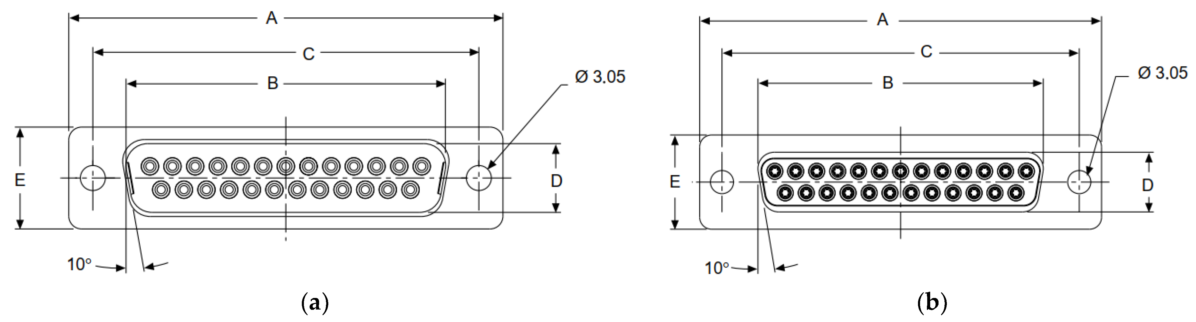
| DB-25 | B | D |
|---|---|---|
| Male Size | 38.96 ± 0.13 mm | 8.36 ± 0.13 mm |
| Female Size | 38.38 ± 0.13 mm | 7.90 ± 0.13 mm |
| Fit Tolerance | 0.52 mm | 0.52 mm |
| Minimum Clearance | 0.32 mm | 0.20 mm |
| Hyperparameter | Value |
|---|---|
| Epoch | 15 |
| Optimizer | Adam |
| Maximum learning rate | 0.001 |
| Weight decay | 0.0001 |
| Mini-batch size | 16 |
| Comparison | ORB | P2HNet |
|---|---|---|
| Mean time for a vision servo step | 43 ms | 15 ms |
| Mean time for the hole search | 8.5 s | 7.8 s |
| Success rate of peg-in-hole | 8/10 | 10/10 |
Disclaimer/Publisher’s Note: The statements, opinions and data contained in all publications are solely those of the individual author(s) and contributor(s) and not of MDPI and/or the editor(s). MDPI and/or the editor(s) disclaim responsibility for any injury to people or property resulting from any ideas, methods, instructions or products referred to in the content. |
© 2023 by the authors. Licensee MDPI, Basel, Switzerland. This article is an open access article distributed under the terms and conditions of the Creative Commons Attribution (CC BY) license (https://creativecommons.org/licenses/by/4.0/).
Share and Cite
Shen, Y.; Jia, Q.; Wang, R.; Huang, Z.; Chen, G. Learning-Based Visual Servoing for High-Precision Peg-in-Hole Assembly. Actuators 2023, 12, 144. https://doi.org/10.3390/act12040144
Shen Y, Jia Q, Wang R, Huang Z, Chen G. Learning-Based Visual Servoing for High-Precision Peg-in-Hole Assembly. Actuators. 2023; 12(4):144. https://doi.org/10.3390/act12040144
Chicago/Turabian StyleShen, Yue, Qingxuan Jia, Ruiquan Wang, Zeyuan Huang, and Gang Chen. 2023. "Learning-Based Visual Servoing for High-Precision Peg-in-Hole Assembly" Actuators 12, no. 4: 144. https://doi.org/10.3390/act12040144