1. Introduction
A permanent magnet synchronous motor (PMSM), which is characterized by simple excitation, compact structure and high-power density, is widely used in sustainable wind power generation, new energy vehicles, rail transit and other fields [
1,
2]. However, as an engine for driving various heavy-load equipment, this type of motor must run in a harsh and even extreme environment for a long time and inevitably suffer from various faults. Hence, it is of great significance to focus on the reliability of PMSM for driving various high-end equipment to minimize faults and errors [
3]. The rotor of the PMSM is a key component, and its faults can severely undermine the working performance of the PMSM. There are three typical rotor faults: eccentricity fault, demagnetization fault (local demagnetization of the permanent magnet) and hybrid fault (the coexistence of the first two faults) [
4]. These three faults have different causes, but the fault characteristics generated by them in PMSM are similar, as specific harmonic components will be introduced into various signals of the motor. These harmonic components can be expressed as [
5]:
where
fs is the power frequency,
k is an integer constant and
p is the number of pole pairs. From Formula (1), the fault characteristics of different fault types share the same frequency, so it is difficult to effectively distinguish these three types of faults by using these harmonic components. However, it is noteworthy that when fixing these three rotor faults, different methods are to be taken and different components are to be replaced, and any misdiagnosis or misjudgment of faults can waste maintenance time and even lead to equipment damage. Hence, it is of great importance to carry out a study on the diagnosis and identification of these three faults for rapid and accurate diagnosis and repair of motor faults.
At present, the research on the diagnosis of PMSM faults mainly focuses on the analysis of a single fault, eccentricity fault or demagnetization fault [
6,
7]. By analyzing items such as the voltage [
8], current [
9], magnetic signal [
10], vibration and torque signals, [
11,
12] of the motor, these studies use different processing methods to extract the fault characteristics of the signals, and the fault characteristics are adopted to recognize the corresponding faults [
13]. Among them, motor current signal analysis (MCSA) is the most commonly used method in industrial scenarios because of its ease of acquisition and ability to realize online detection without the need for additional sensors [
9]. Additionally, due to the symmetry of the topology and winding structure of the permanent magnet motor with a slot-pole ratio of 3/2 and its integer times, many fault characteristics of the motor with faults are set off against each other in each branch of the phase current; in this case, the fault characteristics will disappear in the phase current signals of the fault motor but exist in a certain branch current [
14]. Therefore, the motor branch current signal (MBCS) analysis can be adopted to identify the aforementioned faults.
Traditional time-domain or frequency-domain analysis methods cannot effectively distinguish the three faults because they have similar fault characteristics in various signal time domains and frequency domains. Against the backdrop of the rapid development of big data and artificial intelligence, the machine learning method based on data analysis can be used to realize online detection, identification and accurate diagnosis of multiple types of faults in PMSM [
15]. Linear discriminant analysis (LDA), a supervised learning algorithm, is employed to identify multiple faults of the PMSM, in which frequency-domain harmonics of the current serve as the classification characteristic to recognize the eccentricity fault, demagnetization fault and interturn short circuit fault in the PMSM [
16]. Although the results show that LDA has a high accuracy in recognition, there is a lack of other available methods to compare and verify the effectiveness of LDA. The changes of the d-q shaft voltage of eccentricity fault, demagnetization fault and interturn short circuit fault of PMSM can also be used as a fault classification characteristic and combined with machine learning algorithms, such as k-nearest neighbor (KNN), LDA and quadrature discriminant analysis (QDA), to classify the three types of faults [
17,
18]. However, classifiers such as LDA and KNN suffer from problems of over-fitting and present low accuracy in processing categories with a small amount of nonlinear samples. Furthermore, there are also other classifier models available for fault classification, such as neural networks [
19], supporting vector machines (SVMs) [
20] and deep learning [
21].
An SVM enjoys good generalization possibilities, so it can better solve problems caused by nonlinearity and a small number of samples than other classifiers. SVM was used for stator winding fault detection and classification in PMSM, showing good classification performance [
22]. However, the performance of the SVM is largely dependent on parameter selection, so SVM is often integrated with parameter optimization algorithms, such as a genetic algorithm (GA) and particle swarm optimization. Advanced deep learning algorithms, such as convolutional neural networks (CNN), have also been adopted to diagnose and classify faults in PMSM [
23], but CNN requires a larger size of sample data, higher-quality hardware and more calculation time compared with other traditional machine learning algorithms, such as the SVM. To sum up, it is the current focus of research to combine a generalized parameter optimization algorithm with SVM as the classifier for multifault classification in PMSMs [
24].
In the abovementioned machine learning algorithms, characteristics of frequency-domain signals of fault in PMSM are extracted as the classification characteristic, while the time-domain characteristics are usually ignored. Eccentricity fault and demagnetization fault have very similar current frequencies, so it is difficult to distinguish them. In the field of mechanical system fault diagnosis, there are well-established methods for signal time-domain feature extraction, such as analyzing the characteristic factors of signals [
25]. The extraction of time-domain fault characteristics is performed in a more direct way and the fault characteristics involved can be well maintained during signal changes, so time-domain fault characteristics have the potential to be taken as the classification indicator. The commonly used methods for time-domain characteristic extraction include wavelet transforms (WT) [
26], Hilbert–Huang transforms (HHT) [
27], etc., but these methods are influenced by the window functions and have problems with mode mixing. Taking extracted characteristic factors as the characteristic vector for fault classification is adopted in this paper because this method has high sensitivity and is free from influences of other factors.
Based on the work and results shown in the literature [
14], this paper uses motor MBCS as the fault signal for studying the diagnosis as well as the classification of the three faults of PMSM: eccentricity fault, demagnetization fault and hybrid fault. First, the MBCS is extracted from a healthy motor with various faults. The extracted MBCS was subtracted from the MBCS during normal operation of the motor for residualization and then normalized. Second, the MBCS characteristic factors were extracted after the residual normalization process and were used as features for fault classification to construct the characteristic vector. Third, the GA-SVM algorithm was used to establish classification models for three rotor faults in PMSM. Fourth, the fault motor data are obtained by value calculation and the classification results of the GA-SVM algorithm are compared with those of other commonly used machine learning classification algorithms so as to prove the feasibility of the method in this paper.
2. Theoretical Analysis on PMSM Rotor Faults
In this section, the fault characteristics of three faults (eccentricity fault, demagnetization fault and hybrid fault) are analyzed and their similarities and differences are also compared, thus providing a theoretical basis for the extraction of the fault characteristic vectors required for the subsequent classification of the classifier in this paper.
2.1. Analysis of Induced Electromotive Force
The analysis of the healthy motor model is necessary before establishing models for fault motors. This paper first focuses on the analysis of the induced electromotive force generated by a rotor in the stator slot. According to the armature reaction of a permanent magnetic motor, the permanent magnet in the rotor generates an induced electromotive force
E(
t) in the stator winding when the motor is rotating.
E(
t) can be obtained by calculating the derivative of flux linkage
ψs, as shown in Formula (2).
where flux linkage
ψs is a function correlated to the location of the rotor angle
θr and can be expressed as:
where
r is the air gap radius;
l is the axial length of motor;
Nn is the function amplitude of the stator winding distribution with a reference angle
θs;
Bn is the density amplitude of the flux covering the surface of a single slot winding. At a constant rotational speed,
θr =
ωr t, in which
ωr is the mechanical angular velocity, and the induced electromotive force
E(
t) can be expressed as:
It can be seen from Formula (4) that the induced electromotive force is influenced by the magnetic flux density function, or the flux density on the surface of the slot winding. In a healthy motor, the induced electromotive force varies periodically and there are no harmonic components. However, when the motor is faulty, whatever the type of fault, the magnetic flux density function is influenced.
2.2. Influence of Eccentricity Fault on Induced Electromotive Force
Rotor eccentricity refers to the uneven distribution of the air gap length between the rotor and stator of a motor within the circumference. In a healthy machine, the air gap length between the rotor and stator is evenly distributed, but in a machine with an eccentricity fault, the distribution is uneven. A rotor eccentricity ratio is divided into three categories: static eccentricity (SE), dynamic eccentricity (DE) and hybrid eccentricity (HE).
Taking dynamic eccentricity as an example, this paper analyzes the influence of rotor eccentricity on the induced electromotive force. As shown in
Figure 1, when the rotor rotation center axis coincides with the stator center axis but not with the center axis when the rotor is stationary, the air gap length changes with rotor rotation. The change in air gap length can lead to a change in the air gap permeability of the motor, thus causing a change in the air gap flux magnetic density of the motor. The detailed process is shown as follows:
When DE occurs in PMSM, the air gap length at any mechanical angle changes with the motion of the rotor, as shown in
Figure 2.
δ, the air gap length of eccentricity fault, is expressed as:
where
δh is the length of the radial air gap when the motor is healthy and
e is the eccentric distance.
The air gap permeability can be expressed as:
where
ε denotes the eccentricity degree, and
ε =
e/
δh. Since
ε and the cosine function are both smaller than one, contents below the third item in Formula (6) can be ignored. The air gap permeability can also be expressed as:
where
ws =
pwr,
ws is the electromechanical angular velocity and
p denotes the number of pole pairs in a permanent magnetic motor. According to Ampere’s Law,
Bs, the air gap flux density of the motor stator, can be defined as:
where
μ0 is the vacuum magnetic permeability;
js is the current density of the inner surface of the stator;
j0 is the peak value of the current density. Formulas (7) and (9) are substituted in Formula (8) to get Formula (10).
When the ignored part of Formula (6), the effect of the winding structure and loading conditions of the motor, are all considered,
Bs, the air gap flux density of the motor’s stator, can be expressed as:
Formula (11) represents the change in
Bs when the motor suffers dynamic eccentricity, where
n is a positive integer. On the main magnetic circuit of the motor, the air gap flux relates to the stator surface flux. The existence of stator reluctance can lead to a magnetic potential drop, so
Bn can be estimated as:
where
η is used to mathematically express the change in
Bn corresponding to
Bs. It is usually in the range of [0, 1]. When Formula (12) is substituted in Formula (11), the stator surface flux density
Bn of the motor with DE fault can be expressed as:
Formula (13) represents that when DE occurs in the motor, there will be (1 ±
n/
p)
fs harmonic components in
Bn. Due to the change in
Bn, such harmonic components will also appear in the induced electromotive force of the motor, which can be evidenced by Formula (4). Therefore, we consider the higher power part neglected in Formula (6). When the motor suffers DE, it is for sure that various electrical signals will appear at the specific frequency of the fault harmonics. The frequency of these faulty harmonics can be expressed as:
where
fs is the power frequency of the motor.
Eec(
t), the induced electromotive force when eccentricity fault occurs, can be expressed as:
2.3. Influence of Demagnetization Fault on Induce Electromotive Force
A demagnetization fault refers to the partial or complete loss of the ability of the permanent magnet in the motor rotor to generate magnetic flux. High temperatures and overloading are the main causes of irreversible demagnetization. As analyzed in the literature [
14], according to the armature reaction of a permanent magnetic motor, demagnetization of the permanent magnets in the rotor generated in a single slot is irregular in the counter electromotive force. This is because the flux density generated by a demagnetized permanent magnet decreases and when this permanent magnet acts on a specific slot, the generated induced electromotive force decreases, while the induced electromotive force generated by other permanent magnets that are not demagnetized remains unchanged. Under such circumstances, there is a distortion of the induced electromotive force generated in a stator slot within one mechanical cycle.
Ede_slot, the counter electromotive force generated by the fault motor rotor in a stator slot, can be expressed as [
14]:
where
Vslot is the amplitude of a counter electromotive force generated by a healthy motor in a stator slot;
Kde indicates the demagnetization degree of a single permanent magnet;
p is the number of pole pairs of the motor and
fe is the fundamental frequency of the motor.
Due to the phase difference of the induced electric potential in each slot, according to the principle of induced electromotive force superposition, the branch induced electromotive force of the healthy AC motor is the superposition of the induced electromotive forces of each slot of the branch, which can be expressed as:
where
kN1 is the coefficient of motor winding;
G is the winding coefficient, which can be expressed in Equation (18).
q is the number of slots per pole per phase, and
q = Q/2
mp;
a is the number of the branch of the motor. Taking Equation (16) in Equation (18) into Equation (17) for calculation, the branch current
Ede_b is expressed as:
The analysis in the literature [
14] shows that for such a symmetrically winding permanent magnetic motor whose slot-pole ratio is 3/2 or its integer times, (this type of motor can be divided equally into several small units with 3
n slots per group of two poles. These small units are evenly distributed over a space of 360 degrees.) there is partial demagnetization, the fault characteristic harmonics in the phase-induced electromotive force and current will set off against each other, and the periodic distortions of the phase-induced electromotive force and current disappear. In order to observe the characteristics of signal distortion after the motor fault, the MBCS of the motor is thus selected to analyze the demagnetization fault of a permanent magnetic motor. The harmonic frequency of a demagnetization fault can be expressed as:
2.4. Influence of Rotor Fault on Current
According to the motor voltage equilibrium equation, the relationship between
Efa (counter electromotive force of the fault motor) and
ifa (current of the fault motor) is expressed as:
where
R and
L represent the resistance and inductance of the motor, respectively. When the motor rotates at an angular velocity of
ω, the current in Formula (21) can be expressed by the phasor.
The voltage and current of the AC permanent magnet motor are triangular periodic functions, as is the counter electromotive force. When there is a rotor fault in the motor, the fault components generated in the counter electromotive force lead to the appearance of the same specific fault components in the current.
In conclusion, whether it is an eccentricity fault or a demagnetization fault, the magnetic flux density generated by the motor rotor will be certainly affected, thereby affecting the counter-electromotive force of the motor, so that a specific frequency harmonic component appears in the counter-electromotive force. These harmonic components lead to the appearance of the same harmonic components in the current. For a hybrid fault, which includes both eccentricity faults and demagnetization faults, there exist characteristic frequencies of the two faults in counter electromotive force and current. Additionally, it can be seen from Formulas (14) and (20) that the frequencies of fault harmonics are similar, indicating that it is difficult to accurately classify eccentricity faults, demagnetization faults and hybrid faults by analyzing their frequency-domain fault characteristics.
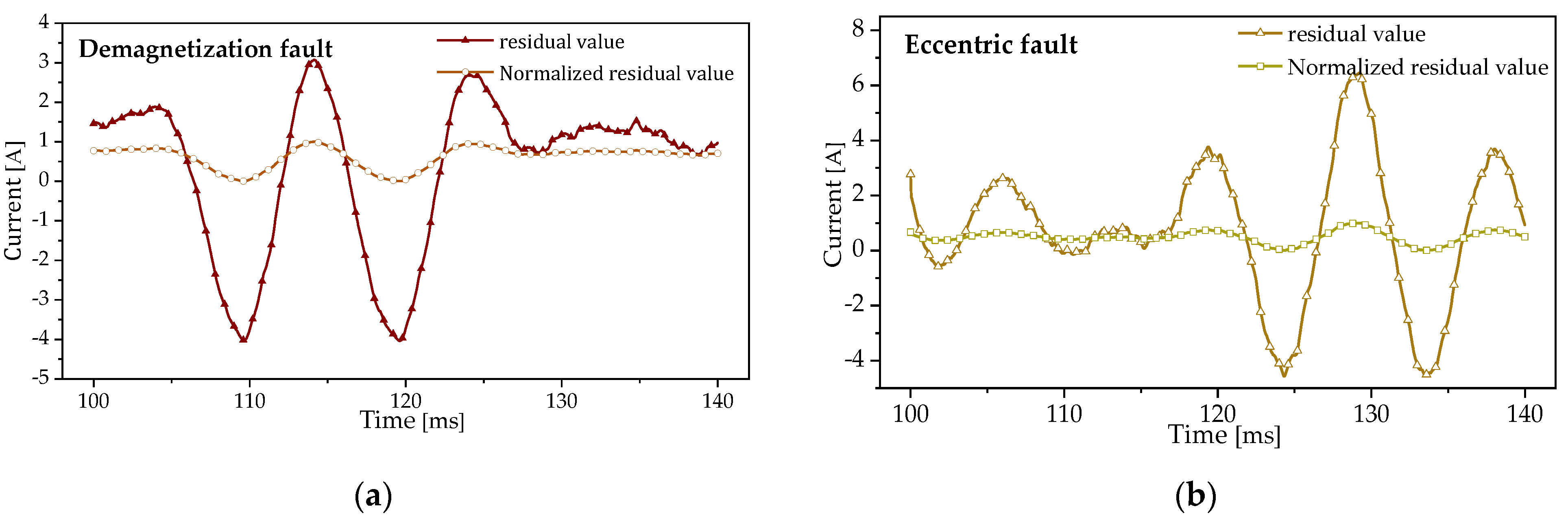
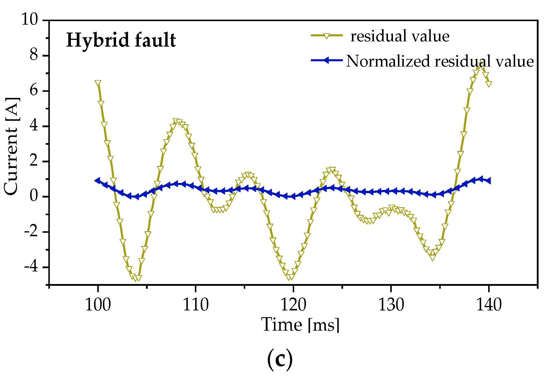
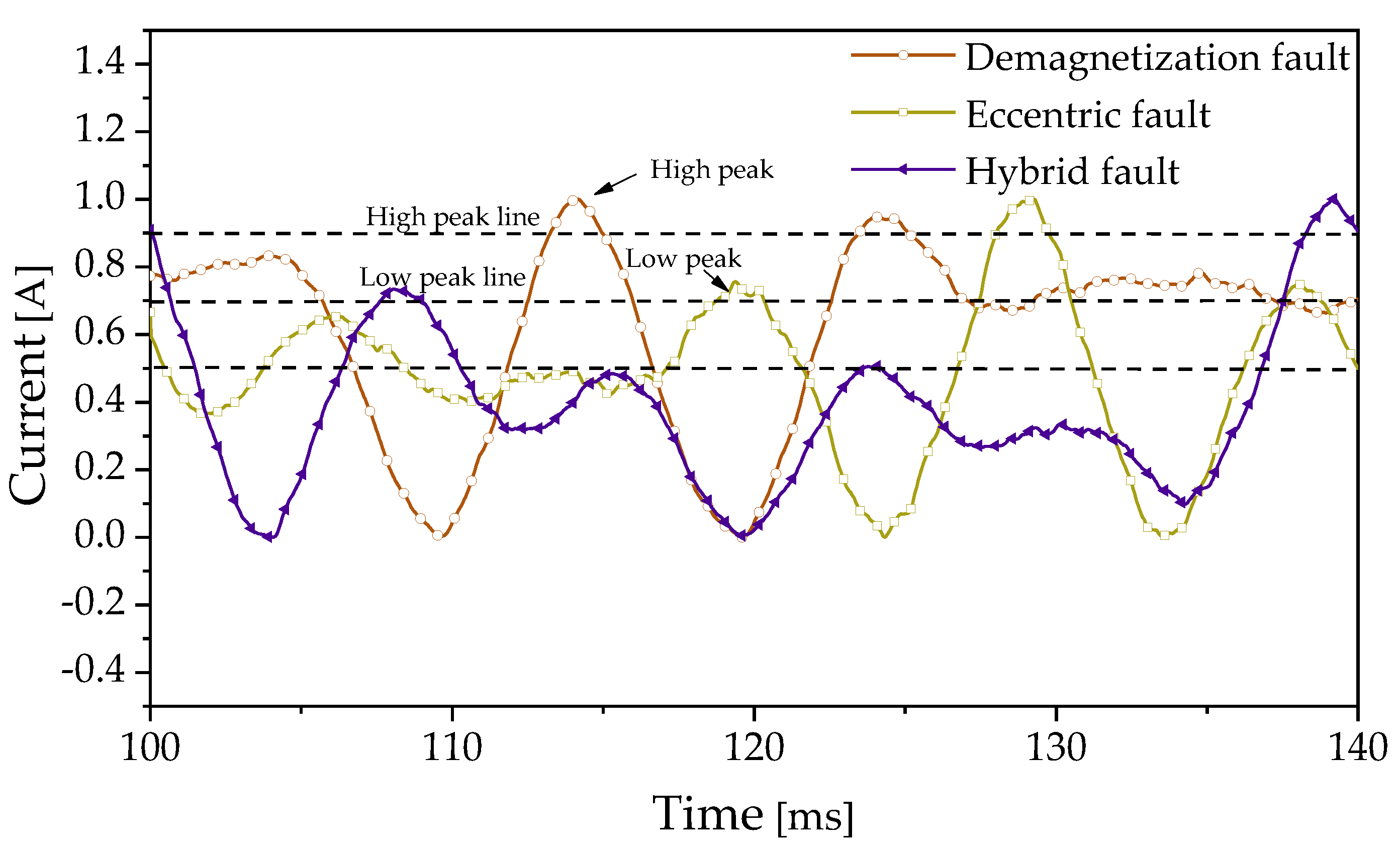
It can be seen from Formulas (15) and (19) that although all three types of faults lead to the appearance of similar harmonic components in the counter electromotive force of the motor, the three types of faults cause this distortion for varied reasons and there are differences in the induced electromotive force time domain. For a demagnetization fault in which several certain permanent magnets are demagnetized, and the counter electromotive force reduces only when the fault permanent magnet rather than the healthy one passes through a certain slot during a mechanical cycle of the motor motion; it is not the case for an eccentricity fault in which the overall air gap flux density presents distortion, so the counter electromotive forces within the whole mechanical cycle are affected. This paper analyzed these three faults in terms of the time-domain characteristics of signals. The characteristic vectors of fault classification were constructed by extracting the characteristic factors of signals, and then these time-domain characteristic factors were identified by machine learning algorithms to classify the three types of faults.
4. Fault Classification and Diagnosis Algorithm
This section is divided into three parts: first, introduce the optimization process of SVM parameters by GA; second, the GA-SVM model is trained and tested by using the fault characteristic vector samples obtained before; third, evaluate the accuracy of the GA-SVM model in classifying different faults and compare its classification result with those of other commonly used classification algorithms so as to verify the effectiveness of the method proposed in this paper.
4.1. Diagnosis Principle Based on SVM
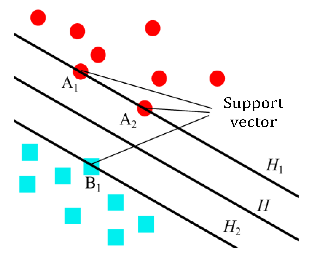
SVM is a binary classification model whose core lies in maximizing the “minimum interval”. By establishing the kernel functions, SVM maps inseparable data to a high-dimensional space and seeks a maximum interval hyperplane for data classification, as shown in
Figure 8.
In
Figure 8, the square represents Sample A, the round represents Sample B, and H is the optimal classification line for the optimal hyperplane.
H1 and
H2 are the parallel lines of the two types of sample points closest to the optimal classification line H, respectively. The distance between
H1 and
H2 is the classification interval. The sample points
A1,
A2 and
B1 on the two lines are the points closest to
H in the two types of samples, which are called support vectors.
In the same inner product space
D, there are many hyperplanes. Any hyperplane can be expressed as:
where
ω is the linear predictor vector, and
b is the offset. Assume
L = {(
x1,
y1), …, (
xi,
yi),…, (
xm,
ym)} (where
i = 1, …,
m) as the sample set and
yi = {1, −1} as the classification label. If
xi belongs to the first type,
yi = 1; if xi belongs to the second type,
yi = −1. The optimal classification hyperplane can not only realize accurate classification but also maximize the classification interval and thus converts to the problem of solving a second order convex programming.
In Formula (24),
ξi is the slack variable;
m is the total number of samples;
φ(
xi) is the characteristic mapping;
C is the penalty factor, which is used to balance the model complexity and loss error. The kernel function of SVM is the inner product function which aims to segment the samples in high-order vectors. Whether the kernel function is suitable or not hinges on the classification effect of SVM. There are three common kernel functions: radial basis function, linear kernel function, and polynomial kernel function. Radial basis function is used as the kernel function of SVM in this paper, which is expressed as follows:
where
γ is the regularization parameter of the kernel function. As SVM is essentially a binary classifier, multiple binary classifiers can be established to diagnose different types of rotor faults; in this case, various motor faults can be classified by using only one solution.
4.2. SVM Parameter Optimization Based on GA
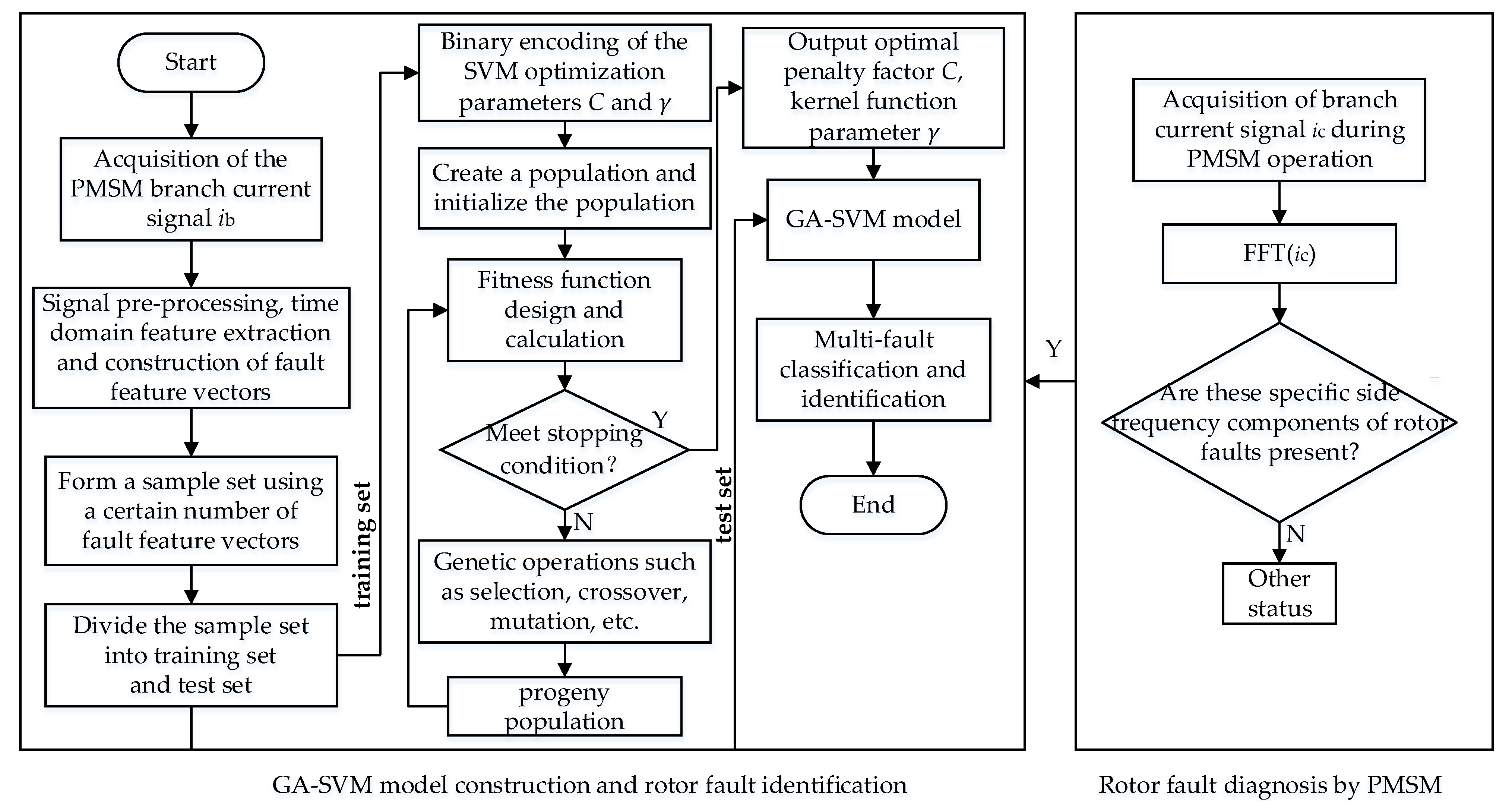
For SVM, the selection of penalty factor C and the kernel function parameter γ greatly influences the generalization ability of input samples and the classification accuracy. However, the selection of C and γ is subject to subjective factors, so it is hard to pick out the optimal values in practical scenarios. For this reason, GA is used in this paper to find out the optimal values of C and γ in the SVM. The basic principle is to introduce the GA during the establishment and training of the SVM classifier so that the search property of GA can facilitate the excellent performance of the SVM classifier. The detailed operation steps are as follows:
Step 1: Acquisition of branch current signals ib of PMSM operation under different operating conditions after the occurrence of different types of rotor faults.
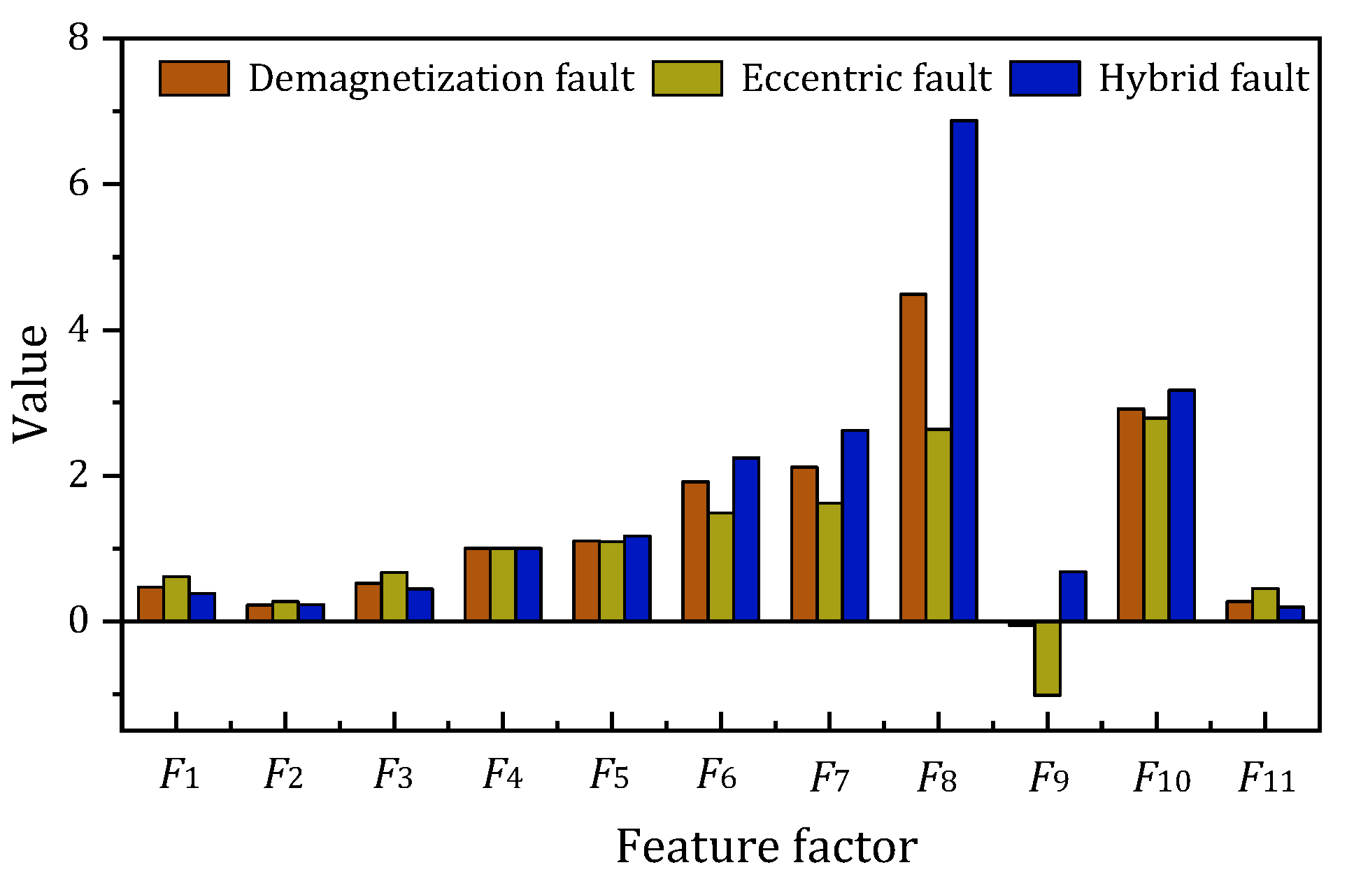
Step 2: The time-domain waveforms of the acquired branch currents ib are preprocessed and the time-domain features are extracted to construct the fault feature vectors for fault classification. These certain numbers of fault feature vector samples constitute the sample set, and they are divided into training set and test set.
Step 3: Input training set samples. Binary encoding of the SVM parameters for which optimal values are sought, and determination of the population size and population initialization.
Step 4: Design the fitness function and calculate the fitness. Determine whether the fitness meets the termination condition. If it is not satisfied, then the individuals in the population take the genetic operations such as selection, crossover and mutation to obtain the offspring population and recalculate the offspring population fitness. Continue to determine if the termination condition is met. Iterate until the termination condition is met.
Step 5: When the loop iteration is performed until the termination condition is satisfied, parameter binary decoding is performed and the optimal C and γ are output.
Step 6: The sought optimal parameters C and γ are assigned to the SVM (GA-SVM model), and the GA-SVM model is trained in combination with the training set. After training, a test set is used to perform a multi-fault classification test.
Step 7: The branch current signal ic during PMSM operation is acquired and the branch current ic is subjected to Fourier transform to obtain the frequency spectrum. The frequency spectrum is determined whether there is a significant increase in the fault harmonic component of (1 ± n/p)fs.
Step 8: Determine the presence of significant characteristic harmonic components in the branch current ic spectrum and then preprocess the branch current ic time-domain waveform and extract time domain features. The feature vectors are constructed and brought into the GA-SVM model for rotor fault identification.
The flow chart for constructing the GA-SVM model and using GA-SVM for rotor fault diagnosis and identification of PMSM is shown in
Figure 9.
5. Results and Analysis
The data used in this paper were obtained from finite element simulation. Taking the difference between signal samples of the same type of fault into consideration, this paper randomly sets different fault degrees for each type of fault and simulates the working conditions of motors with different loads. Sampling within the whole cycle was completed in different time frames to obtain 94 groups of MBCS in each group of various faults, so the total number is 282 groups of signals. Data preprocessing and feature extraction are performed on each group of data to obtain 94 sets of feature vector samples for each group of faults, for a total of 282 groups of characteristic vector samples.
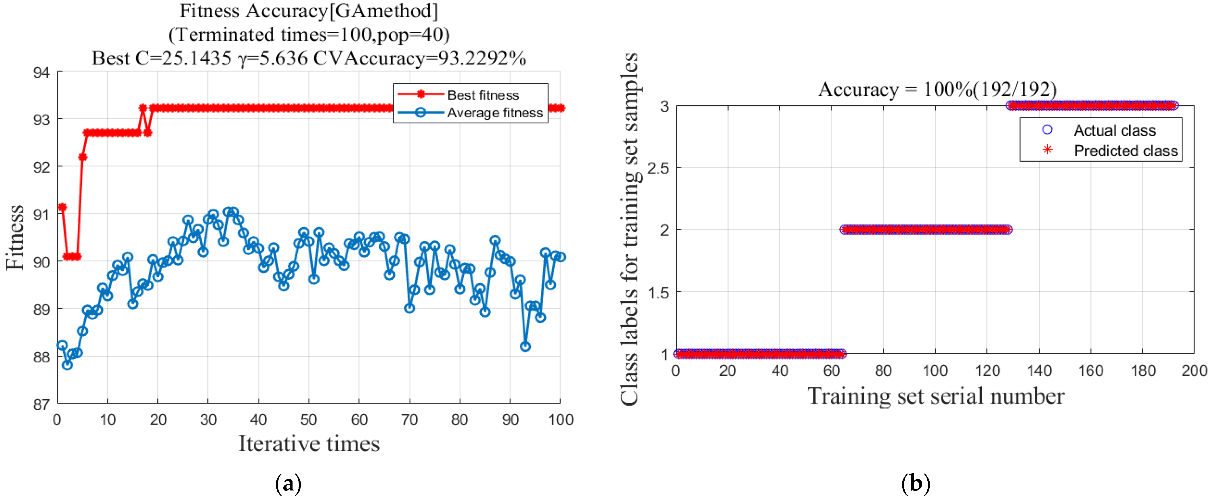
The obtained data are divided into training set and test set samples; the training set data are used for model training and the test set data are used to test the classification accuracy of the model. The training set data is used for model training, and the test set data is used for testing the accuracy of the model. Sixty-four sets of samples from each class of data are classified as the training set, with 192 sets of data. The remaining 30 sets of data in each group are combined into the test set, and the number of samples in the test set is 90. The training set samples are brought into the model for iterative C, γ-parameter training and optimization search, and classification training. The model is built by adding labels to the PMSM rotor fault types, and the output of the model is set as: category 1 to represent demagnetization faults, category 2 to represent eccentricity faults, and category 3 to represent hybrid faults. The parameters of the GA-SVM training model were set as follows: the population size is 40 (pop); the number of iterations was selected as 100 (terminated times); the value interval of the optimal parameter (C, γ) was limited to [0, 100].
Figure 10a shows the iterative operation diagram of the genetic algorithm to optimize
C and
γ by GA. According to the optimal reserve strategy, the fitness of the optimal individuals in the population gradually increases and steadily stands at 93.2%. The optimal value of the parameter
C was calculated to be 25.1435, and the optimal value of the parameter
γ was calculated to be 5.636.
Figure 10b shows that the predicted class values of all samples are exactly equal to the actual class values, indicating that the predicted class of GA-SVM is exactly the same as the actual class. The GA-SVM model training set rotor fault classification results achieve an accuracy of 100%, indicating that the combination of
C and
γ achieves optimal classification performance.
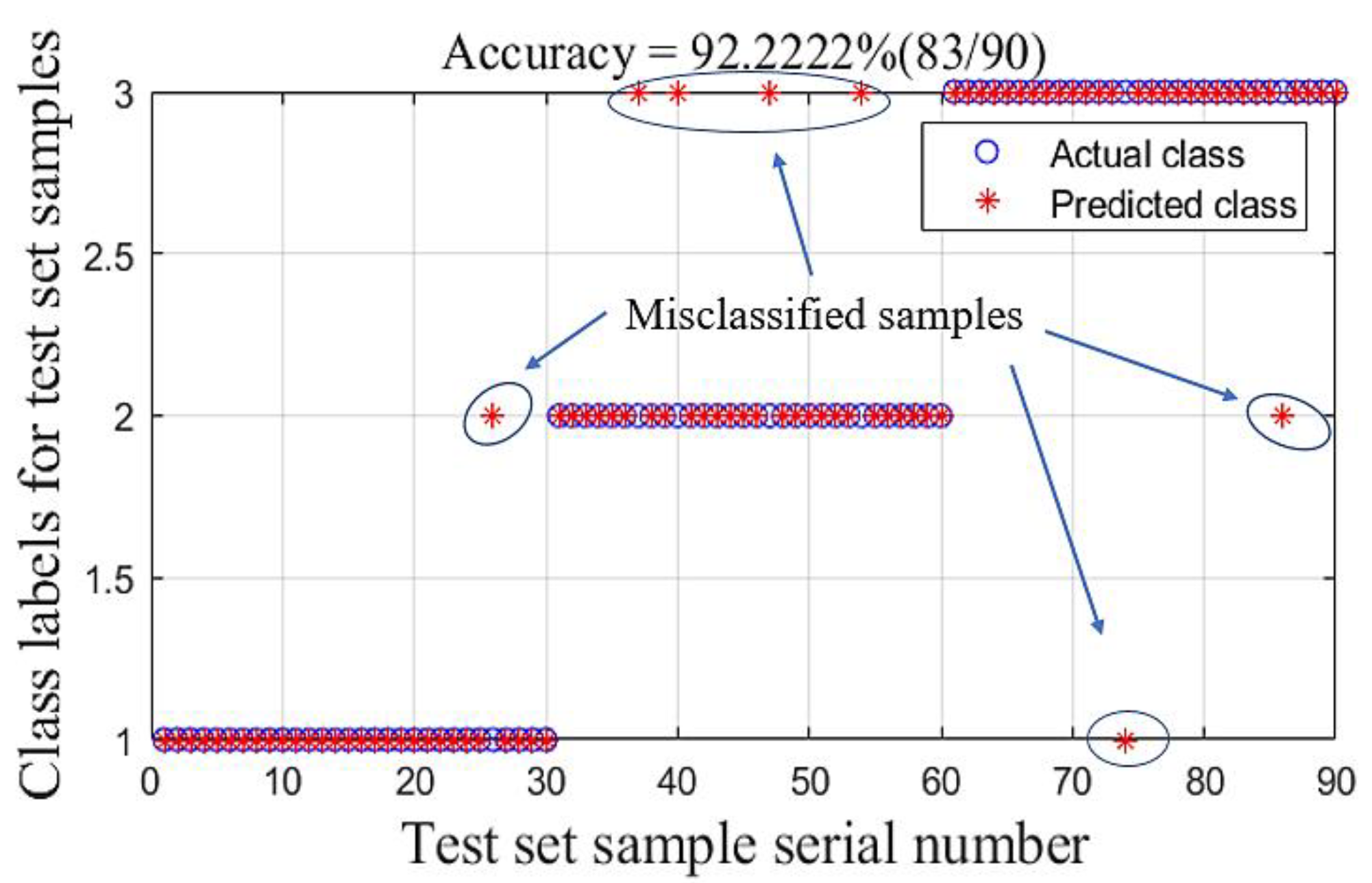
Finally, 90 groups of samples in the testing set were introduced to the GA-SVM model to get the classification results, and the accuracy of the results was quantitatively evaluated. The diagnosis results are shown in
Figure 11.
The test set classification results of the GA-SVM model for rotor faults are shown in
Figure 11. There are some samples in the figure where the predicted category values do not match the actual category values, and most of the misclassified samples are category 2 samples that are misclassified as category 3 (the samples that were misclassified have been marked in
Figure 11). However, overall, the classification accuracy of the test set samples reached 92.22%, and the trained GA-SVM model has high accuracy in the PMSM rotor fault classification problem, which can effectively solve the classification problem of rotor faults in PMSM.
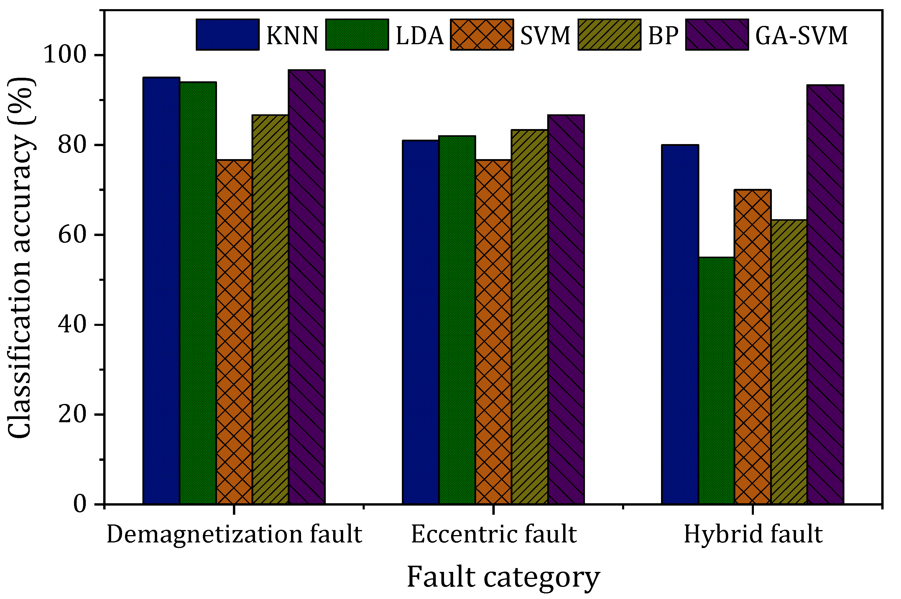
In order to further illustrate the superiority of the GA-SVM model in identifying the rotor faults of PMSM, several commonly used classification algorithms such as KNN, LDA, SVM and BP were selected to compare with the classification accuracy results of the GA-SVM model. The obtained 282 characteristic vector samples will be trained by the above classification models, and the classification results are shown in
Figure 12.
Figure 12 indicates that the GA-SVM model has higher accuracy than other classification algorithms in classifying each type of fault; in particular, when there is a hybrid fault in PMSM, the KNN and LDA models show obviously lower accuracy than the GA-SVM model.
Table 5 shows the average accuracy of commonly used classification models. It can be seen that the average accuracy of the GA-SVM model reaches 92.2%, which is much higher than that of other algorithms. In addition, compared with traditional SVM models, the GA-SVM model also presents higher average accuracy, indicating that the penalty factor (
C) and the kernel function parameter (
γ) of SVM optimized by a genetic algorithm can effectively improve the diagnostic performance of SVM.

 ,
, 


