1. Introduction
With the rapid development of China’s social economy and the implementation of the Western Development Strategy, significant progress has been made in tunnels and underground engineering, showing a trend in deep-buried, super-long, and extra-large development. The increasing number of tunnels in complex environments poses enormous challenges to the safe construction and healthy operation of engineering projects [
1,
2,
3]. Engineering practice has shown that in situ stress is one of the important basic data requirements for geological environment and crustal stability evaluation and engineering design and construction, and it is also the fundamental force that causes deformation and failure when the environment in which the rock mass is located changes [
4,
5]. With the increasing attention paid to engineering safety, it has become an essential task to study the distribution characteristics of in situ stress in the project area in advance during the line selection, layout, design, and construction stages of super-long and deep-buried tunnels.
In situ stress testing is the most direct way to understand the in situ stress field in engineering areas. At present, the commonly used in situ stress testing methods include hydraulic fracturing (HF) [
6], over-coring [
7,
8,
9], hydraulic testing of pre-existing fractures (HTPF) [
10], surface stress relief for rock mass, and so on [
11]. However, during the implementation process, it was found that there are still the following shortcomings when using in situ stress testing. On the one hand, most super-long and deep-buried tunnels are subjected to the occurrence environment of long tunnels, large burial depths, complex geological structures, and stratum lithologies. Owing to high cost, long-term testing, and unfavorable on-site measurement conditions, it is difficult to carry out in situ stress testing for the entire line, and the results only reflect sporadic stress fields located near the limited measurement points. On the other hand, the application conditions of in situ stress testing methods are relatively strict, and it is difficult to fully meet this strict requirement in the actual testing process. For example, the over-coring method requires the tested rock mass to meet uniform, continuous, isotropic, and linear elastic conditions, while the HF method assumes principal stress along the vertical direction [
8,
9,
10]. However, under extremely high-stress environments, core disking often occurs in boreholes, which greatly reduces the success rate of in situ stress testing [
12,
13]. Additionally, in high-stress environments, the testing equipment pressure is limited. Insufficient equipment pressure leads to the formation of wellbore cracks, making it difficult to implement in situ stress testing methods. The HTPF method assumes that the tested rock mass is uniform, continuous, and linearly elastic. When the distance between the tested fractures is greater than 50 m, a stress gradient value needs to be provided [
10]. At present, due to limited measured data and geological information, studies typically use numerical simulation technology to invert the distribution characteristic of 3-D in situ stress fields for the entire research area [
14,
15,
16]. However, the accuracy of the in situ stress field obtained using this method depends not only on the reliability and representativeness of the in situ stress testing data but also on numerous factors such as numerical models, boundary conditions, and geological parameters [
17].
Numerous engineering practices have shown that a substantial amount of rock mass deformation and failure information is often revealed during the excavation process, although this phenomenon is harmful to engineering construction safety. However, from another perspective, failure phenomena provide an indirect basis for estimating the magnitude and direction of in situ stress. In recent decades, many scholars have conducted in-depth research on the relationship between testing methods, such as the borehole fracturing method [
18,
19,
20,
21], the borehole stress relief method [
22,
23,
24,
25,
26], and the HF method [
6,
10], and in situ stress. Then, the magnitude and orientation of in situ stress based on failure phenomena and limited testing data can be estimated. With the improvement in computer technology and the continuous development of numerical simulation technology, the comprehensive use of in situ stress testing technology, rock excavation failure phenomenon, back analysis, and numerical simulation methods to obtain the distribution characteristics of the in situ stress field of deep underground projects, has gradually become a commonly used analysis method [
27,
28,
29,
30]. This method compensates for the problems of limited or unreliable in situ stress measurement data and provides a feasible approach for determining the 3-D in situ stress field of super-long and deep-buried tunnels. However, in the case of soils and soft rocks, the numerical models used to evaluate stresses and displacements must be based on unconfined conditions, not limited to oedometric parameters [
31]. In addition, the back analysis method has been widely applied in computational simulations of tests (namely, direct analyses), sensitivity analyses for the optimal design of experiments, model reduction procedures, and other aspects [
32,
33]. At the same time, it plays an important role in the mechanical characterization of materials and the non-destructive assessment of possible damages to industrial plant components and civil engineering structures and infrastructures [
34].
It can be seen that the current research on initial stress field inversion mostly focuses on how to improve the fitting degree between the calculated stress values at the measurement points and the measured ones, while the research on the effectiveness and representativeness of the measured data for subsequent back analysis is not in-depth enough. In addition, existing inversion methods lack recognition of failure phenomena in the surrounding rock during tunnel excavation. Thus, the obtained in situ stress field cannot match well with the failure characteristics of the surrounding rock. To address the above issues, a comprehensive analysis method that can estimate the 3-D in situ stress field of tunnels passing through multiple geological tectonic units based on incomplete measured stress data and geological information is proposed. The method is designed for use prior to the excavation of deep-buried long tunnels. Firstly, by conducting a macroscopic analysis of the regional geological structure, topography, and failure phenomena of pre-excavated small tunnels, the strength of the tectonic stress field and the orientation of the principal stresses in the tunnel sections are preliminarily determined. Secondly, by use of stereographic projection technology, the reliability of the in situ stress measured results is analyzed, and representative measurement points are selected that can reflect the distribution characteristics of in situ stress in the project area on the whole. On this basis, the FDM and MRA methods are used to complete a back analysis of the in situ stress field in the project area. The method above was directly applied to a super-long and deep-buried tunnel project in Qinling, and the in situ stress distribution characteristics of the tunnel sections at different mileages were obtained. Finally, the typical failure phenomena in the surrounding rock encountered during the excavation of the project were investigated, and targeted treatment measures were also proposed.
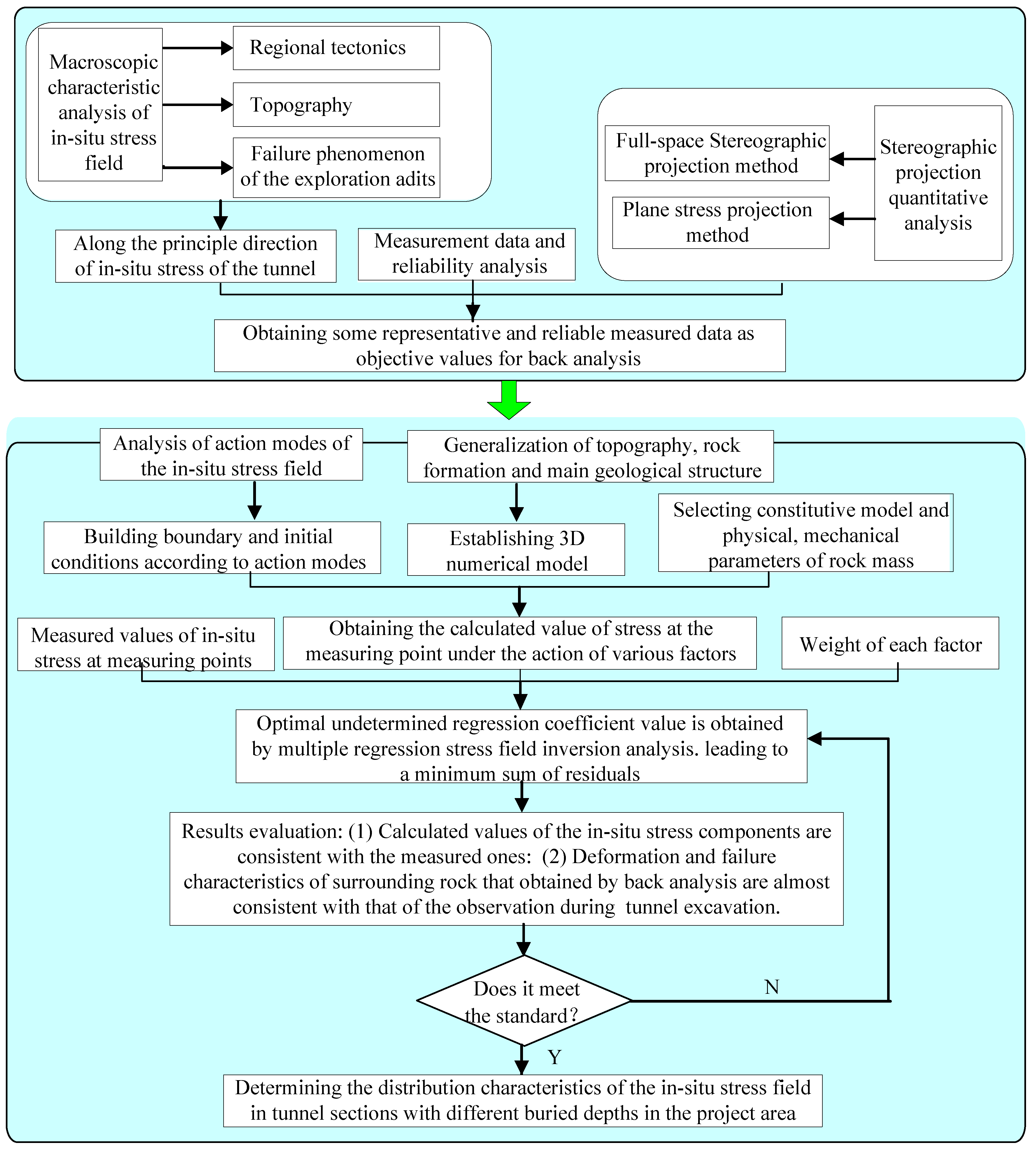
2. In Situ Stress Estimation Method for Super-Long and Deep-Buried Tunnels
During the construction of deep-buried tunnels, it is necessary to excavate some small tunnels (such as exploration, auxiliary, and pilot tunnels) in advance to expose stress-induced failure phenomena in the surrounding rock (such as peeling and sudden rock burst phenomena). Although stress-induced failure phenomena are harmful to construction safety, from another perspective, they also provide a new method to explore certain characteristics of in situ stress.
This study proposes a multivariate information integration method for estimating the in situ stress of deep-buried tunnels based on a small amount of stress measurement data and the pre-exposed stress-induced rock failure characteristics of small tunnels in advance. A flowchart for this method is shown in
Figure 1. The basic principle and implementation process for the method are described in detail below:
2.1. Macroscopic Characteristic Analysis
Using an analysis of the tectonic history and current tectonic activity within the project region, the orientation of the tectonic stress was inferred as follows:
(1) Using a study on the geological age of the regional geological structure in the project area, the types of main control faults (such as normal, thrust, and strike-slip fault), and the relationship between faults in the near-field zone and tectonic stress, the orientation of the in situ stress field in the project area was preliminarily revealed.
(2) The relationship between the topography and tectonic stress in the project area was studied, and the influence characteristics of the topography on the distribution of in situ stress was preliminarily determined.
(3) In combination with the possible occurrence of failure phenomenon in the surrounding rock of the exploration adits, the strength of the structural stress field and the orientation of the principal stresses in the tunnel sections were preliminarily determined.
2.2. Reliability Analysis and Selection of In Situ Stress Testing Results
Using the in situ stress measurement data, the distribution characteristics of the in situ stress field in the project area were preliminarily analyzed, and the azimuth and inclination angles of the principal stresses were described with stereographic projection technology. Subsequently, the potential deformation and failure characteristics of the surrounding rock of the tunnel were obtained according to the spatial relationship between the measured principal stress direction and tunnel axis. Within the same project area, the measured results should be consistent with the stress state in the macroscopic area. The reliability of the in situ stress measurement should be tested from the following aspects:
(1) When the measured results consider errors, such as rounding, they sometimes do not constitute a stress tensor. Therefore, it is necessary to analyze the complete stress tensor (six components) from the measured values using stereographic projection technology [
30]. The orthogonality of three principal stress directions was examined.
(2) Verification of consistency between the measured principal stress direction and macroscopic regional tectonic stress direction.
(3) Verification of the consistency between the measured stress-induced deformation and failure parts of surrounding rock and the inferred position using the spatial relationship between the principal stress and the tunnel axis.
(4) Combined with
Section 2.1, the representative measurement data that can reflect the distribution characteristics of the in situ stress in the project area are selected for subsequent back analysis of the in situ stress field.
2.3. Multiple Regression Analysis Method (MRA) for an In Situ Stress Field
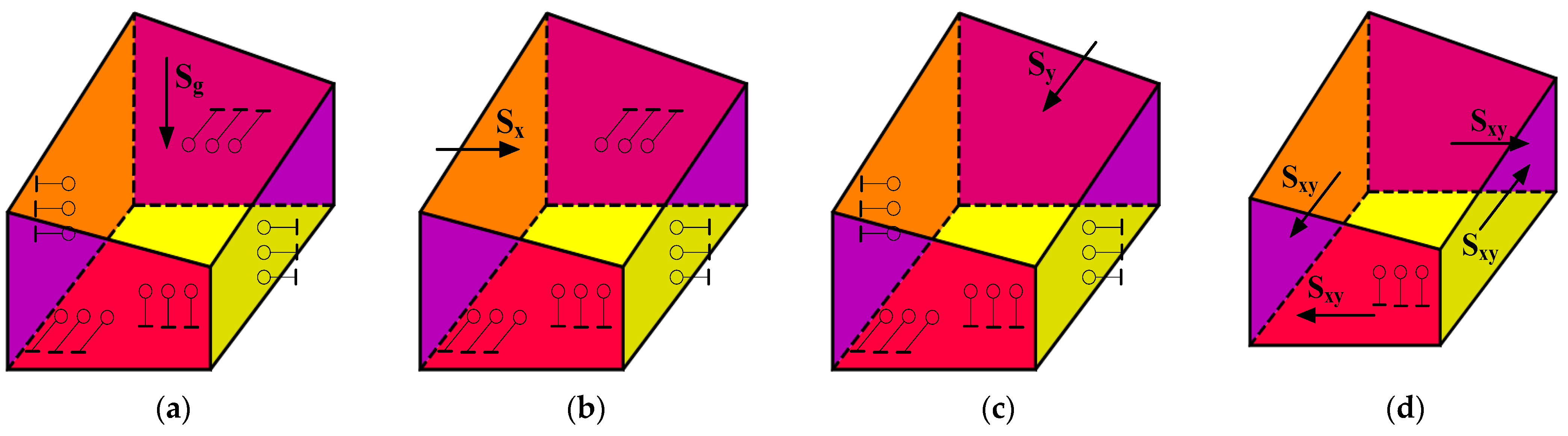
MRA of an in situ stress field is an important method for estimating the stress state in a project area. This method has been widely used in many large-scale underground projects [
17,
26,
35]. Based on the theory of geomechanics, this method establishes a mathematical calculation model by dividing the main components of the in situ stress fields, such as the self-weight and tectonic stress field, and obtains the corresponding weights of each factor using multiple regression analysis so that the fitting error between the calculated and measured stress values at the test location is minimized. Based on current research results [
35,
36], there are four main types of action modes of the in situ stress field in this study. The impact of tectonic action on the in situ stress is achieved by applying unit stress or displacement at the boundary. The load and boundary constraints are plotted in
Figure 2.
The calculation process for the MRA method is described as follows [
37,
38]:
Using the in situ stress field regression value
as the dependent variable and the stress value
σki for each influencing factor as the independent variable, the form of the regression equation is as follows:
where
k is the sequence number of the observation points,
Li is the multiple regression coefficient for the corresponding independent variable,
is the regression-calculated value for the
kth observation point,
σki is the single-column matrix for the calculated value of the corresponding stress component, and
n is the number of working conditions,
i = 1, 2, …,
n.
Supposing that there are
m observation points, each with six stress components, the residual sum of squares
Sc can be obtained as follows:
where
σjk* and
are the measured data and calculated values of the stress component
j at the observation point
k, respectively,
σjki is the numerically calculated value of the stress component
j at the observation point
k under the
i condition, and
l = 1, 2, 3, …, 6 refers to
σxx,
σyy,
σzz,
σxy,
σyz, and
σzx, respectively.
Based on the principle of the least square method, a set of
Li is obtained to minimize the residual sum of squares
Sc, and the solution is unique. The least square method (also known as the least squares method) is a mathematical optimization technique. By minimizing the sum of squares of errors to find the best function that matches the data, it can easily estimate unknown data and minimize the sum of squares of errors between the calculated and measured results. The equation that makes
Sc the minimum is:
Solving the system in Equation (3) and obtaining
n undetermined regression coefficients
L = (
L1,
L2, …,
Ln)
T, the initial in situ stress at any point
P in the calculation region can be obtained with superimposing the calculated values of the finite element in each working condition. That is:
where
is the regression-calculated value of the stress component
j at any observation point
P in the calculation domain and
is the calculated value of the stress component
j at any observation point
P in the calculation domain under the
i condition.
According to Equation (4), the initial in situ stress field in the calculation region is treated as a linear superposition of the self-weight stress field and the tectonic stress field. To ensure that the obtained initial in situ stress field conforms to the actual distribution characteristic of the stress field, the reliability of the regressed in situ stress field was evaluated using two aspects: (1) the calculated values of the in situ stress component were verified to be basically consistent with the measured ones to ensure that the spatial points are consistent and (2) the consistency of the predicted deformation and failure parts in the surrounding rock of the tunnel under the calculated stress field, as well as the observed deformation and failure phenomena during the tunnel excavation, were verified to ensure that the in situ stress characteristics of the local area were consistent.
3. Project Overview: A Case Study
3.1. Project Introduction
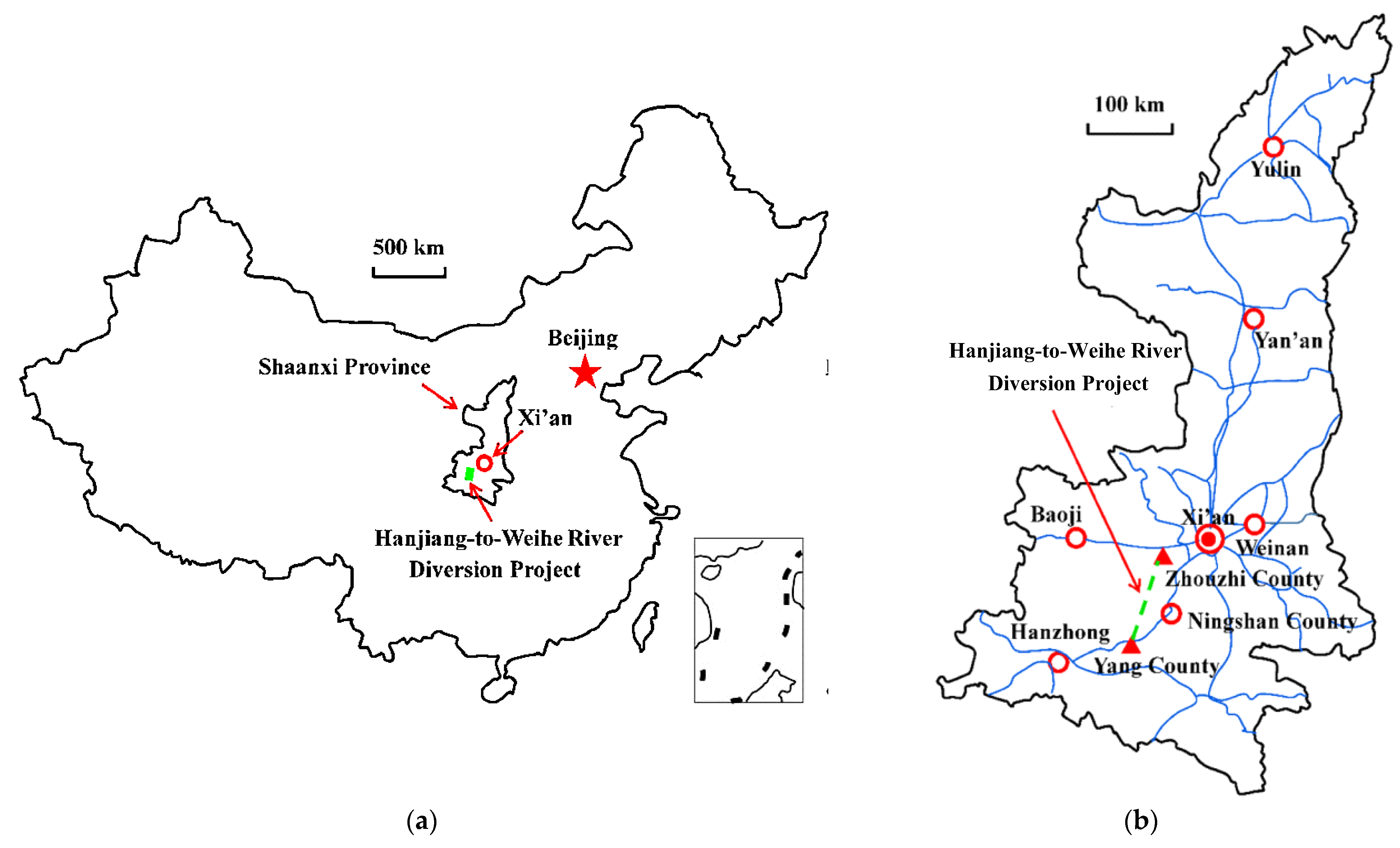
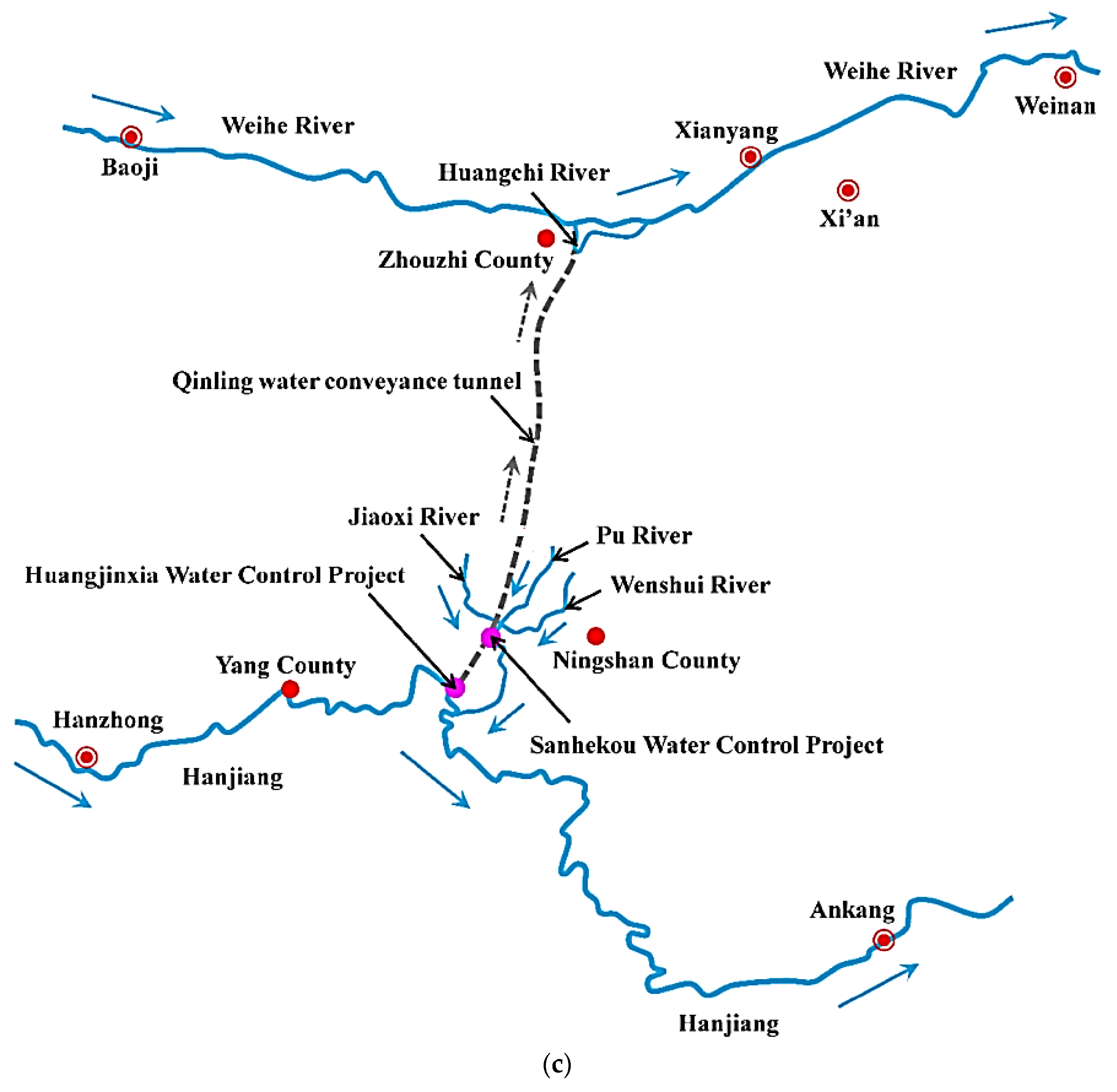
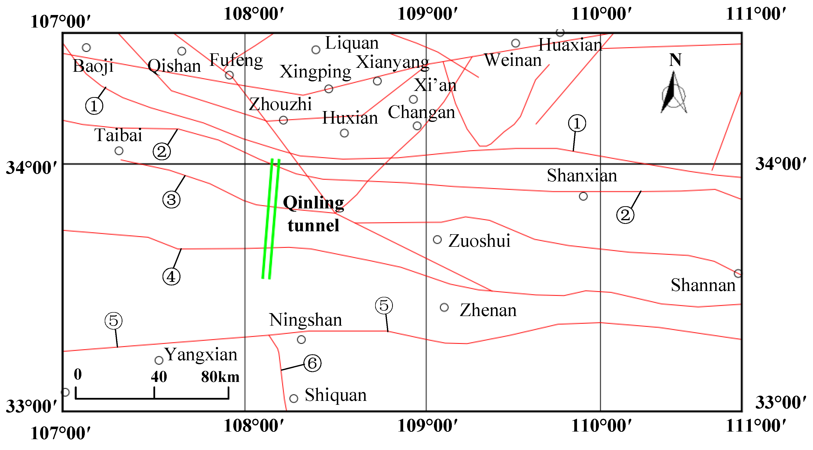
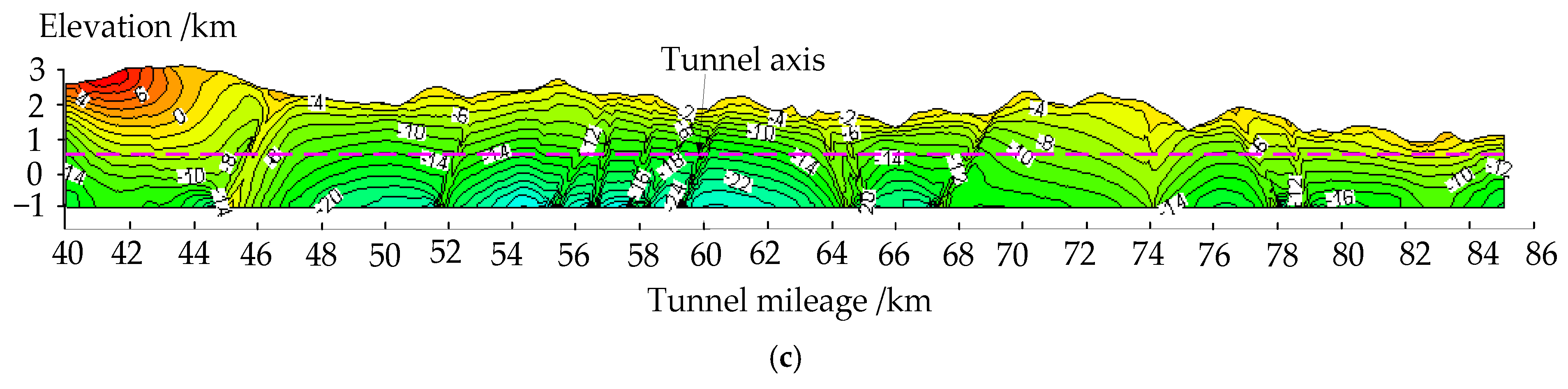
The Hanjiang-to-Weihe River Water Diversion Project, which is called the South-to-North Water Diversion Project in the Shaanxi Province of China, aims to solve the water shortage problem in cities along the Weihe River coast in the central Shaanxi area. The Qinling water conveyance tunnel is a key channel for diverting water from the Hanjiang River to the Weihe River, with a maximum burial depth of about 2002 m, a length of 81.779 km, and an average annual water transmission of 1.505 billion cubic meters. The inlet of the tunnel has a bottom elevation of 537.17 m, and the exit has a bottom elevation of 510.0 m. This study focuses on the north section of the Qinling water conveyance tunnel, which is 41.779 km long (K40 + 000~K81 + 779). The location of the tunnel is shown in
Figure 3.
3.2. Geological Conditions
The project area is located in the northern section of the Qinling tunnel, which mainly includes the geomorphic units of the high and middle mountain areas of the Qinling Ridge, as well as the middle and low mountain areas of the northern Qinling Ridge. Under the influence of neotectonics, a relatively complex geomorphic unit was formed by long-term water erosion and cutting. The construction methods in the project area primarily include a TBM section and a drilling and blasting section. The geological conditions in the different sections are as follows:
(1) The TBM construction section is 25,164 m long (K40 + 000~K65 + 164), and its main lithology is granite, quartz diorite, metasandstone, phyllite, and hornblende schist. The rock mass is weakly weathered to slightly weathered, which is severely affected by geological structures. The joint fractures are relatively developed. The main faults that pass through are QF4, f8, f9, f10, f11, f12, f13, f14, f15, f16, f17, QF3, QF3-1, QF3-2, QF3-3, QF3-4, f18, and f19. The rock mass is relatively integrated, but the local stability of the surrounding rock is poor.
(2) The drilling and blasting construction section is 16,615 m long (K65 + 164∼K81 + 779), and the main lithology is granite, granodiorite, granite porphyry, gneiss, hornblende schist, phyllite with sand, mica schist with chlorite schist, and marble with mica schist. The rock mass is weakly weathered to slightly weathered, which is severely affected by geological structures. The joint fractures are well-developed. The main faults that pass through are f21, f22, f23, QF2, f25, and f26. The integrity of the rock mass is poor, but the local stability of the surrounding rock is good.
The materials in the fault fracture zone are primarily composed of fault mud, breccia, Mylonite, and fragmented rock, which are loose and broken and contain water. The surrounding rock of the tunnel has poor self-stability, and its instability is prone to occur during construction.
4. In Situ Stress Analysis Using Multivariate Information Integration
4.1. Macro Characteristic Analysis
4.1.1. Analysis of the Regional Geological Structures
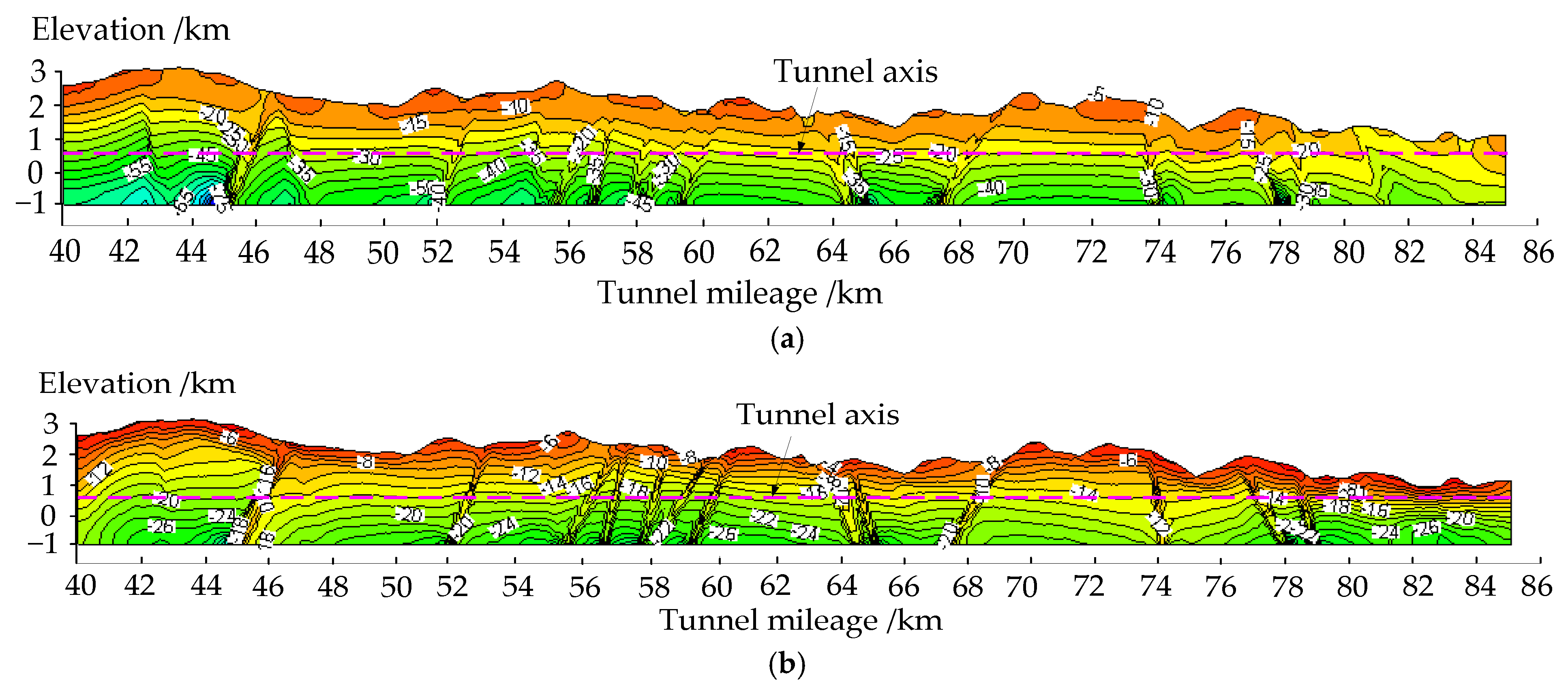
The Qinling water conveyance tunnel belongs to the Qinling Fold System in terms of tectonic units, and its geological structure mainly develops fold and fault structures. It passes through two regional major faults, namely, the Shangnan–Tangzhi fault, which strikes in the EW direction, shows compressive stress, and inclines in the N direction. The Fengzhen–Shanyang fault strikes in the NWW direction, shows tensile stress, and inclines in the N direction. Regional major faults have the characteristics of deep cutting, long extension, and large scale. The strike is mostly in the near EW direction, with a small number in the NE and NW directions, most of which are compressive. The distribution characteristics of major geological structures near the tunnel are shown in
Figure 4. Some domestic scholars have deeply discussed the distribution characteristics of the tectonic stress field in this region using focal mechanisms, numerical analysis methods for microstructure, etc. It is believed that the tectonic stress field in this area is mainly extruded in the NW–SE direction [
40]. This is basically consistent with the characteristics of the regional tectonic stress field in the North China Plate.
In summary, the main compressive stress direction of the modern tectonic stress field in the project area is generally in the NW or near EW direction, and there may be significant deviations in local areas due to the influence of topography, geological structure, and the ancient tectonic stress field.
4.1.2. Analysis of the Topography in the In Situ Stress Field
Existing studies have shown that the distribution of in situ stress in river valleys generally includes a stress relief zone, stress concentration zone, and stress stability zone [
41,
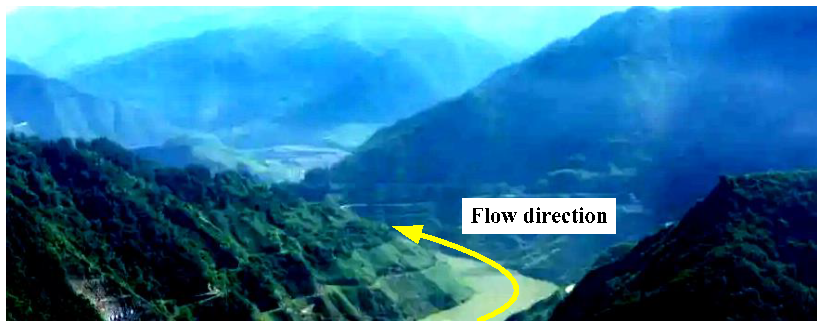
42]. The elevation and maximum burial depth of the Qinling water conveyance tunnel project area are approximately 500 m–2500 m and 2002 m, respectively. The valley is relatively narrow, with a general width of 30–50 m and a natural slope of 40°–60°. The topographic and geomorphological features of the river valley along the tunnel are shown in
Figure 5. The in situ stress testing indicates that the maximum horizontal principal stress direction is mainly in the NW direction outside the tunnel, but it is close to the EW direction inside the tunnel. The overall direction is between NW and EW, which is consistent with the regional structure and topography [
43]. In addition, the lateral pressure coefficient of the maximum horizontal principal stress direction near the river valley outside the tunnel is generally greater than 2.0, indicating that the stress concentration phenomenon in the valley area is obvious. The tectonic stress field is strong, and the testing site is significantly affected by the terrain. The field test results are basically consistent with current research results.
4.1.3. Relationship between Failure Characteristics of the Surrounding Rock and In Situ Stress
Recently, during the construction of the main and branch tunnels, a rock burst was observed. Also, instability in the surrounding rock is relatively common, mainly occurring in the fault fracture zones, weak structural planes, and joint dense zones. In some areas severely affected by geological structures, such as fault zones and lithological contact zones, it is easy to encounter large-scale collapses.
It can be seen that the distribution of in situ stress in the tunnel area is relatively complex. For the surrounding rock of the tunnel with large burial depths of hard and brittle rocks, the tectonic stress field has a strong effect. The stress concentration phenomenon is evident, and rock bursts are prone to occur. For soft rock areas with large burial depths, particularly in areas with fault structures, stress release is the main feature. Large deformation of the surrounding rock and rock mass sliding and collapse are more significant. Therefore, the characteristics of the in situ stress field in the project area are relatively complex, mainly formed by the superposition of self-weight stress and tectonic stress.
4.2. Analysis of In Situ Stress Testing Results
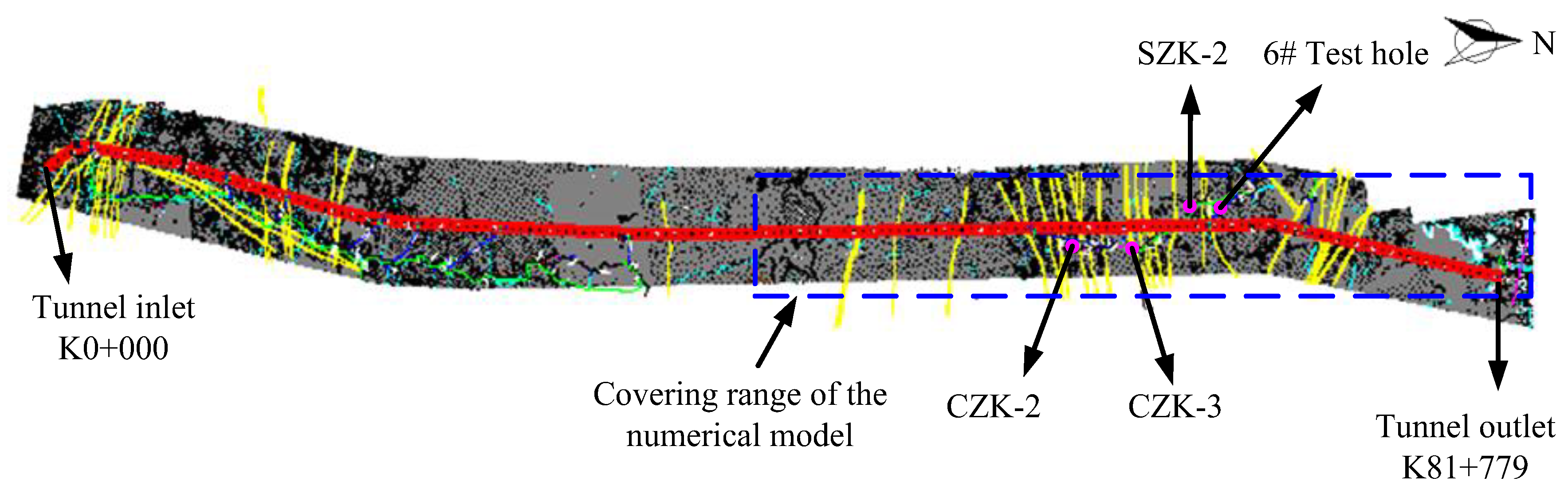
The in situ stress field test of the Qinling water conveyance tunnel mainly uses the HF method and 3-D hydraulic fracturing method. The HF method uses the method recommended by the International Society of Rock Mechanics for in situ stress testing. The principle underlying the 3-D hydraulic fracturing method and its implementation process are detailed in Ref. [
43]. The layout of boreholes for in situ stress testing is shown in
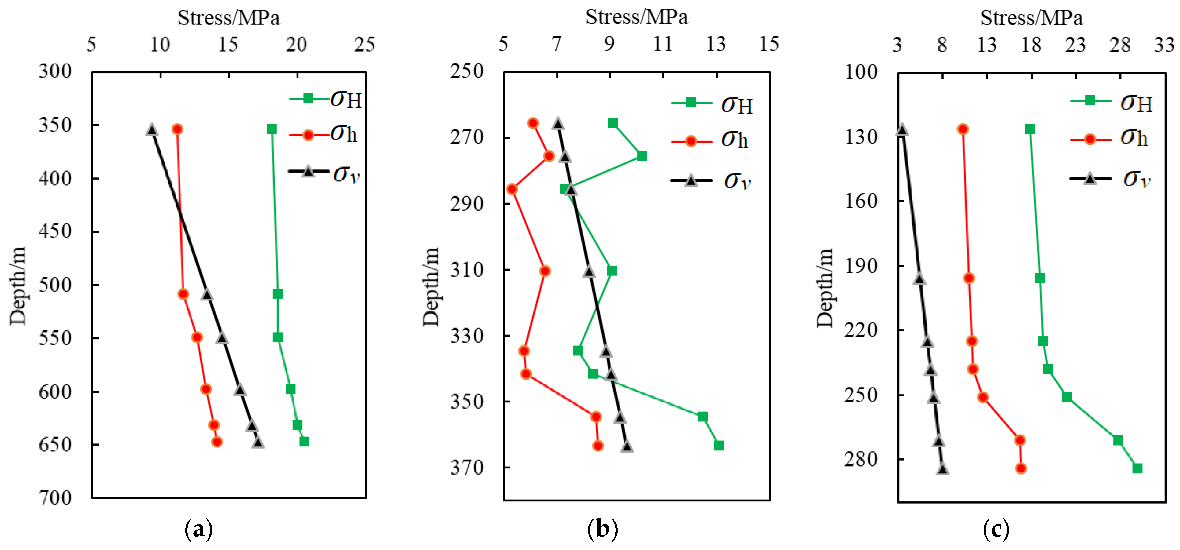
Figure 6. Among them, three deep boreholes, CZK-2, CZK-3, and SZK-2, were created using the HF method. The stress measurement results are shown in
Table 1 and
Figure 7, where
σv is the vertical principal stress,
σH is the maximum horizontal principal stress, and
σh is the minimum horizontal principal stress. The 6# testing section used the 3-D hydraulic fracturing method, and the stress measurement results are shown in
Table 2. The stress components and maximum horizontal principal stress results after coordinate system transformation are listed in
Table 3.
As shown in
Table 2 and
Figure 7, in situ stress in the project area is dominated by horizontal tectonic stress, but there are certain differences in the distribution characteristics of stress among different boreholes. For boreholes CZK-2 and CZK-3, the relationship between the three principal stresses is basically
σH >
σv >
σh, and the maximum principal stress is mainly horizontal. The predominant direction of the maximum horizontal principal stress is N 37° W to N 52° W, and the lateral pressure coefficient of the maximum horizontal principal stress (
σH/
σv) ranges from 0.88 to 1.94. However, for borehole SZK-2, the relationship between the three principal stresses is basically
σH >
σh >
σv. The predominant direction of the maximum horizontal principal stress is N 9° E to N 35° W, and the lateral pressure coefficient of the maximum horizontal principal stress (
σH/
σv) ranges from 2.88 to 5.02.
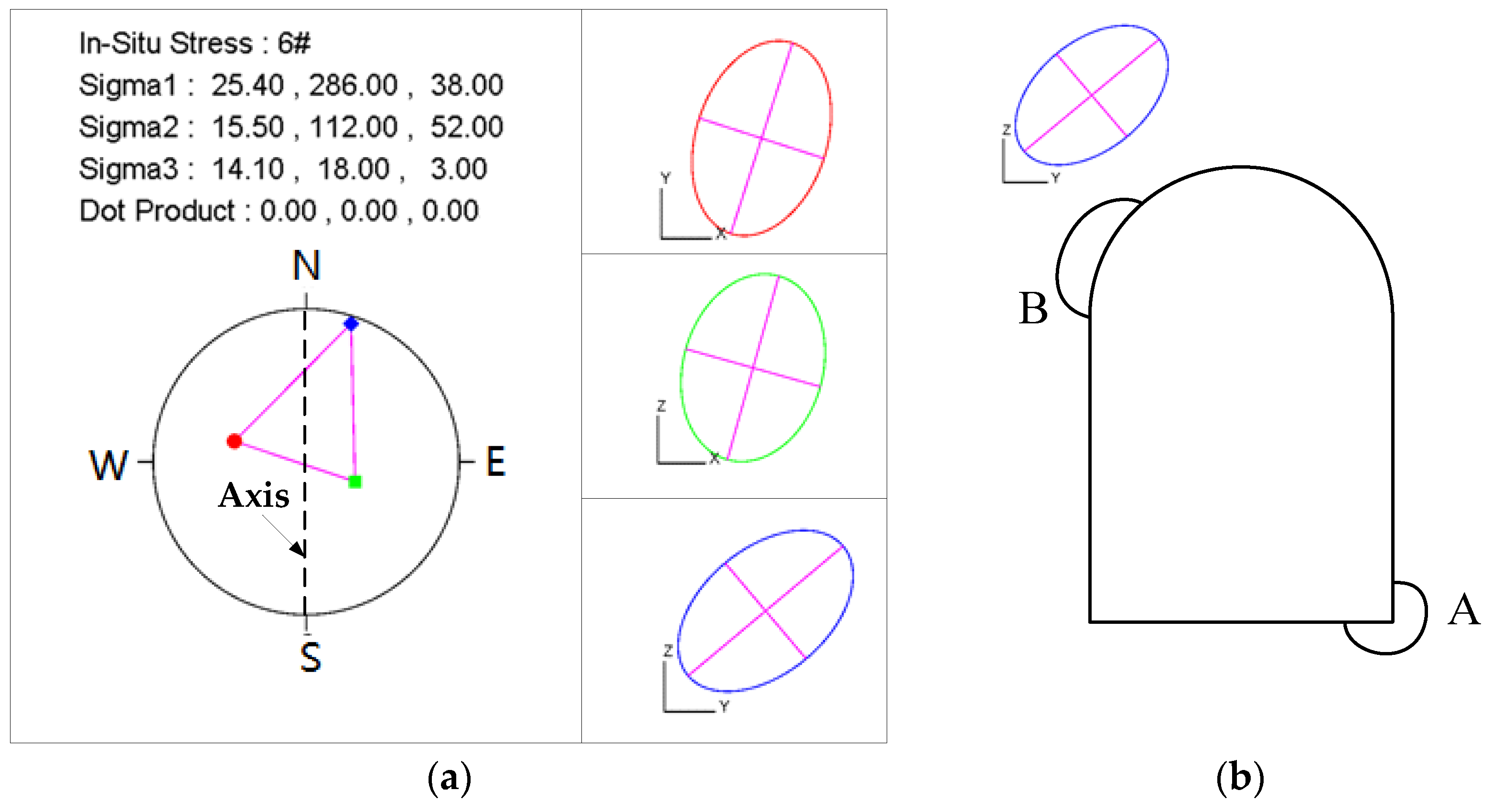
In addition, to meet the requirements for quantitative analysis of in situ measured stresses, the so-called software
‘GeoStress3D V1.0’ was developed using OOP programming technology, the C++ language, and the open graphics library OpenGL. This method not only verifies
the orthogonality of the three principal stresses direction but also determines the in situ stress distribution characteristics at measurement points on each
projection plane using plane projection technology. Using the measurement point
at the 6# testing section as an example, the stereographic projection of a unit vector of typical principal stress orientations and their projection stress
ellipses on the XY, YZ, and YZ planes are shown in
Figure 8a. Also,
Figure 8b shows a plot of the deformation and
failure characteristics of the surrounding rock of the tunnel. In the figure, the
red circle
![Buildings 13 01924 i001]()
, green square
![Buildings 13 01924 i002]()
, and blue diamond
![Buildings 13 01924 i003]()
stand for the unit vector
of the orientation of the maximum, intermediate, and minimum principal
stresses, respectively (same as below). The three numbers behind Sigma (i.e.,
Sigma1, Sigma2, and Sigma3) stand for the principal stress values, azimuth, and
dip angles, respectively. It can be concluded that the long axial direction of the
stress ellipse is inclined to the upper (or lower) reach of the river valley on
the XY (or YZ) plane. On the XZ plane, the long axial direction is inclined to
the inside mountain. Similarly, the projection features of the stresses at
other testing points can also be interpreted.
Thus, the orientation of the maximum horizontal principal stress is orthogonal to the axis of the Qinling water conveyance tunnel (near the NS direction), which is relatively unfavorable for the stability of the cavern. During the actual construction process, some effective measures should be taken to reduce the impact of the secondary stress field on the deformation and failure of surrounding rock after tunnel excavation.
4.3. Selection of Representative Measured Data
Based on the above, it can be concluded that the in situ stress field in the project area has the following characteristics: (1) The in situ stress field is significantly affected by tectonic stress in the shallow part, and as the burial depth increases, the self-weight gradually dominates. (2) The orientation of the maximum horizontal principal stress is between NW and NWW. The lateral pressure coefficient of the maximum horizontal principal stress decreases with increasing burial depth, most of which are less than 1.5. (3) The projection of the measured stress tensor on each plane should conform to the characteristics shown in
Figure 8.
It can be seen that the burial depth of borehole SZK-2 is relatively shallow, and the measured results are greatly affected by the topography and geomorphology. Moreover, the measurement points 9#–12# in borehole CZK-3 are significantly affected by local geological defects. Namely, the above measured results are not representative. Thus, ten measurement points, 1–8#, 13#, and 14#, can represent the overall characteristics of the in situ stress field in the project area, which are selected as the basic information for a subsequent back analysis of the in situ stress field.
4.4. MRA of the In Situ Stress Field
4.4.1. Computational Model and Mechanical Parameters for the Rock Masses
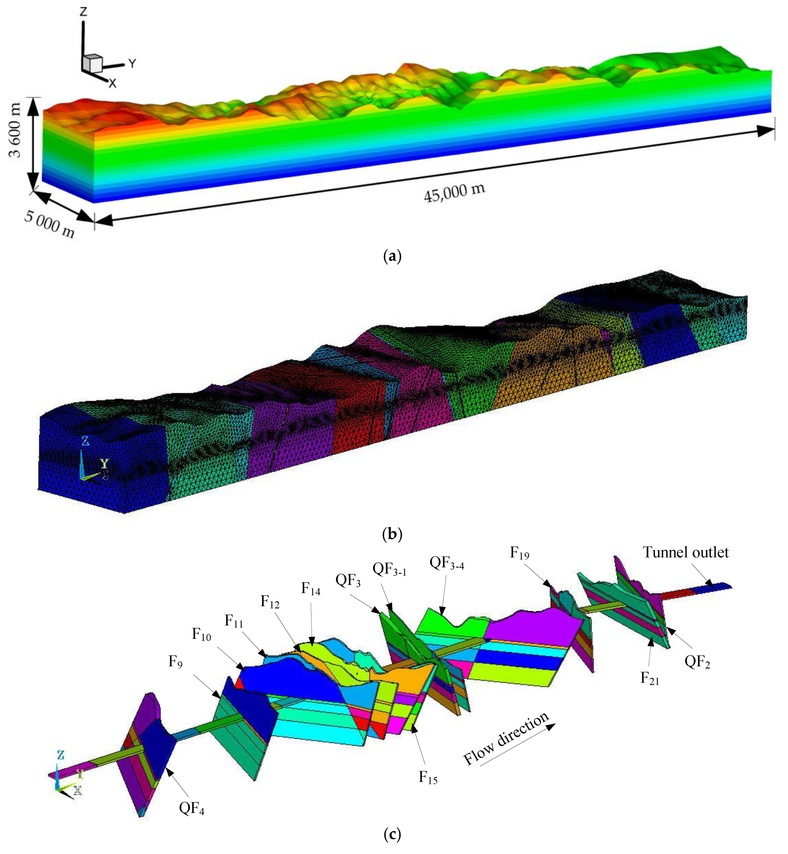
The numerical analysis method is widely recognized as an important approach for estimating the stress state in deep-buried tunnels. Here, the commercial software FLAC3D V4.0 was used for numerical calculation. The computational model corresponded to a region of the rock mass measuring 5000 m × 45,000 m × 3600 m (X × Y × Z, where the positive direction of the X-axis and Y-axis point to the east and north, respectively, and the Z-axis extends upwards from an elevation of −1000 m to the mountain top). The computational model and grid division based on regional geology, topography, and geomorphology are plotted in
Figure 9a,b. In this model, seventeen typical strata and thirteen major faults were included; the main faults are shown in
Figure 9c. In addition, a 3-D solid element (Solid45) was used to establish the finite element calculation model. Different types of strata and faults in the model were simulated using solid units, and the constitutive model was linear elastic. The bottom of the model was constrained, and the tectonic effects were simulated by applying horizontal compressive and shear loads around the model (see
Section 2.3). The number of grid elements and nodes were 185,832 and 1,056,155, respectively. The physical and mechanical parameters of the rock masses are listed in
Table 4.
4.4.2. Back Analysis of the In Situ Stress Field
Based on
Section 2.3, the finite element calculation of regional ground stress field distribution under self-weight stress and three kinds of tectonic action was carried out, and the stress components at the corresponding depths of each borehole were extracted. According to the MRA, the regression coefficients for the four influencing factors affecting the in situ stress field of the Qinling water conveyance tunnel were obtained, and the initial in situ stress field regression equation was preliminarily established as:
where
σcal is the initial regression stress value;
Sg is the self-weight stress value;
Sx and
Sy are the unit extrusion stresses applied along the horizontal boundary in the
x and
y directions, respectively; and
Sxy is the unit-tangential stress applied along the
x and
y directions in the horizontal plane.
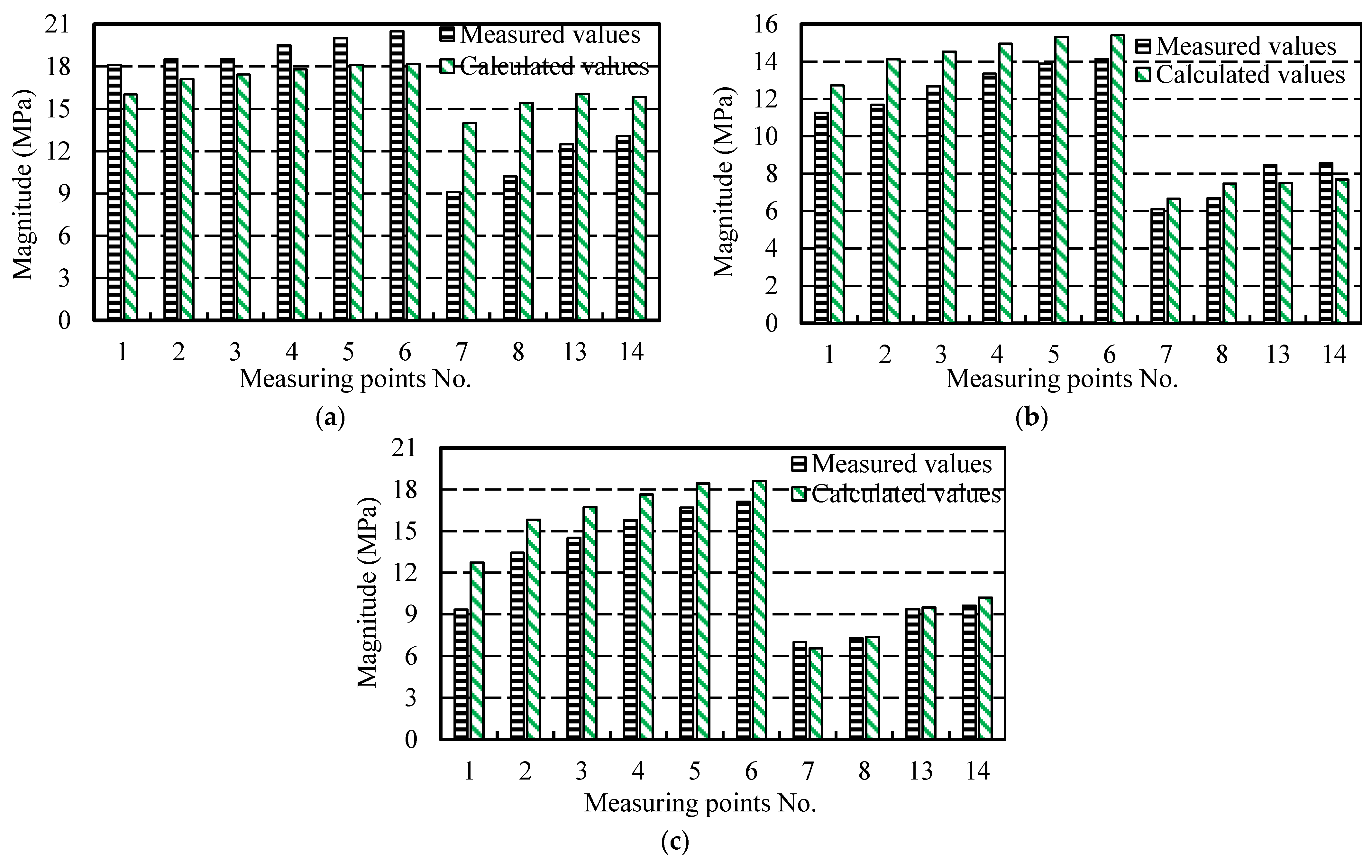
By comparing the calculation values with those measured (
Table 5), it is found that the multiple correlation coefficient is 0.956, and the F-test observed value is 50.51. When the significance level is 0.05, the critical value F
0.
05 (4, 24 − 4 − 1) is 2.93, namely, F > F
0.
05. Thus, the precision of the back-analysis is satisfactory.
Figure 10 plots the relationship between the measured value of the principal stress and the calculated values at the measurement points. It can be seen that the measured values at most measurement points are numerically close to the calculated ones, and the absolute error of the stress component is mostly not more than 2 Mpa. The overall error is relatively small. In addition, the maximum horizontal principal stress azimuth at each measurement point is in good agreement with the measured data. The maximum absolute error of the principal stress azimuth is approximately 12°, generally not exceeding 6°. It can be concluded that the optimized back analysis method used in this paper is credible and behaves well when simulating the initial in situ stress field in the project area under complex conditions.
4.5. Distribution Characteristics of the In Situ Stress Field
Figure 11 shows the distribution of the three principal stress contours along the longitudinal section of the axis of the Qinling water conveyance tunnel. The distribution characteristics of the in situ stress field of the tunnel can be described as follows:
(1) The magnitude of in situ stress near the axis of the tunnel increases with the burial depth. The maximum burial depth is approximately 2000 m. The magnitude of the maximum principal stress is as high as 52.65 MPa.
(2) The tunnel has a long route that passes through different geological structural units, resulting in a very complex distribution of the in situ stress field in the surrounding rock. Specifically, when the burial depth of the tunnel is less than 1000 m, the in situ stress field at the tunnel elevation is mainly horizontal, that is, σH > σZ > σh. the lateral pressure coefficient of the maximum horizontal principal stress (σH/σv) ranges from 1.02 to 1.88. When the burial depth of the tunnel is greater than 1000 m, the maximum principal stress at the tunnel elevation is primarily owing to its own weight, that is, σZ > σH > σh. The lateral pressure coefficient of the maximum horizontal principal stress is between 0.7 and 1.1. In general, the lateral pressure coefficient of the principal stress gradually decreases with an increase in burial depth.
(3) Due to the influence of topography and faults, a certain stress concentration phenomenon occurs at the foot of slope. However, there are obvious stress release phenomenon in the fault zone and adjacent areas, and the maximum horizontal principal stress direction also undergoes a certain deviation. Furthermore, the fault and its surroundings show that the vertical principal stress in the rock mass is greater than that of the maximum horizontal principal stress, that is, σZ > σH > σh.
(4) The in situ stress in the fault zone changes sharply, and the stress contour appears to be a phenomenon of ‘hump and mutation’. After reaching a certain distance, it tends to stabilize. Further analysis showed that at the end of the fault, each stress component and principal stress have evident stress concentrations. However, the position of the stress concentration zone is asymmetric at both ends of the fault, which is primarily caused by the difference in the angle between the boundary stress ratio of the fault and the maximum principal stress.
5. Failure Mechanism of the Surrounding Rock and Treatment Method
5.1. Description of Failure Characteristics during Tunnel Excavation
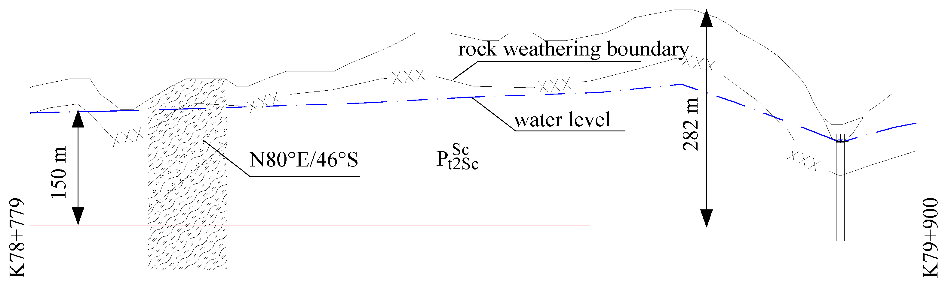
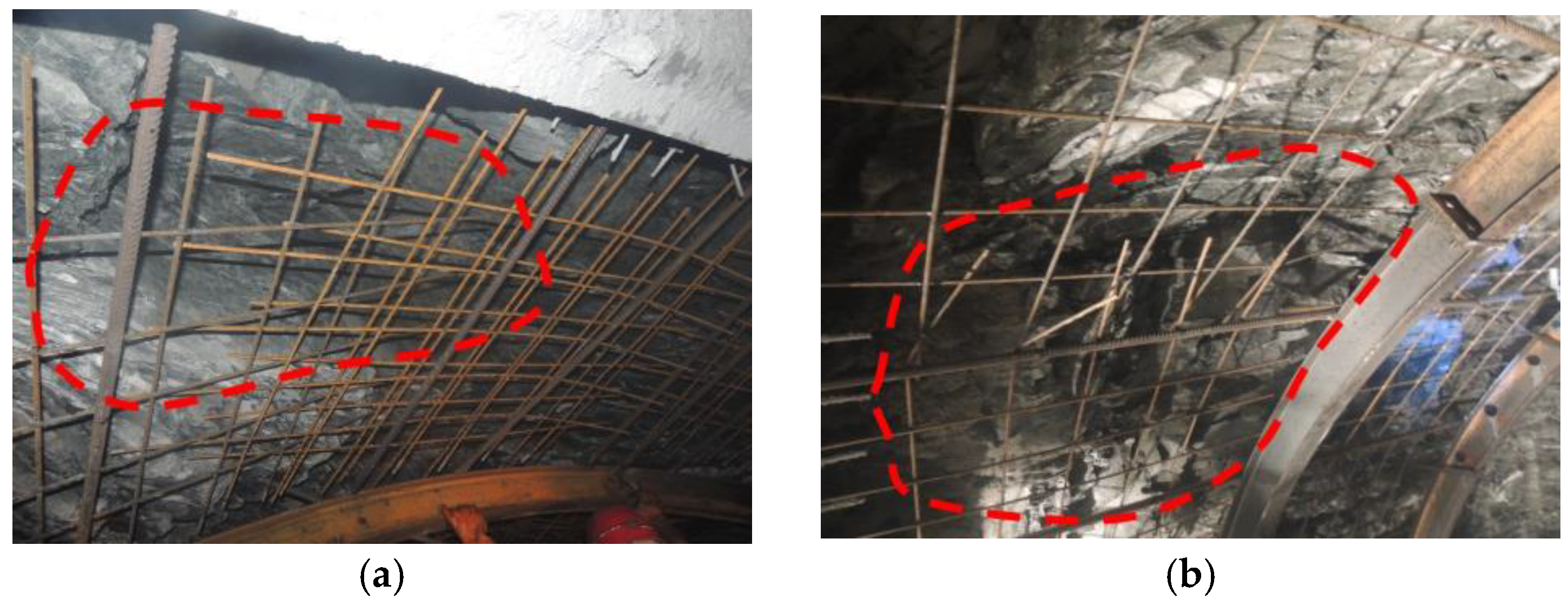
Figure 12 shows the geological profile along the axis of the Qinling water conveyance tunnel from K79 + 900 to K78 + 779. The burial depth of the tunnel in this section ranges from 183 m to 282 m, and more than ten large collapses occurred during its construction. The collapses are mainly located on the left arch and side wall. The height of the collapsed cavity is about 8 m, with a longitudinal extension of 4 m and a circumference of 6 m. After the collapse, the initial convergence deformation of the surrounding rock was large, reaching 10 mm/day. A typical failure image obtained in the surrounding rock is shown in
Figure 13.
5.2. Failure Mechanism Analysis
According to the geological data obtained during the excavation, the lithology of the locally damaged area is primarily mica quartz schist with local carbonaceous schist, high mica content, soft lithology, and joint development. Three groups of joints, i.e., straight, smooth, and no filling, are well developed, which can be described as follows:
(a) J1: N 20° W/60° S, spacing from 0.1 m to 0.2 m, extending approximately 1 m.
(b) J2: N 15° W/60° N, spacing from 0.3 m to 0.5 m, extending about 2 m.
(c) J3: N 30° E/55° N, spacing from 0.05 m to 0.1 m, extending about 1 m.
Due to the extremely smooth surface of mica schist, low internal friction angle, and poor shear resistance, unloading deformation occurred during the tunnel excavation. Plastic deformation subsequently occurred when exposed to water, which made it easy for the blocks to cause slip damage to the side wall. It can be concluded that the accident in this project was mainly owing to the collapse caused by the fragmentation of rock mass, soft lithology, and the formation of sliding blocks due to the cutting of the structural plane.
5.3. Targeted Treatment Method and Rationality Verification
5.3.1. Support Measures
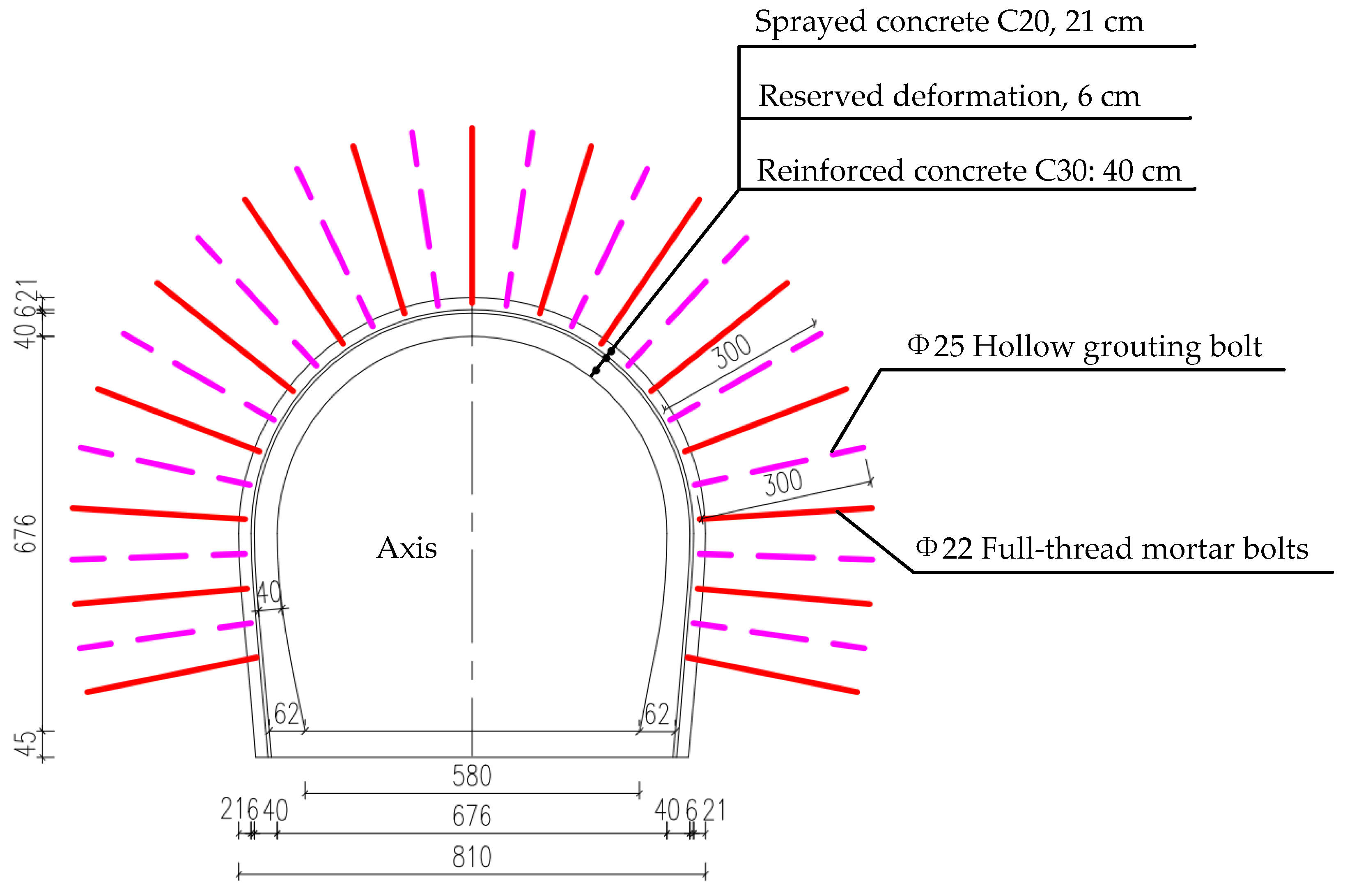
Based on geological data and engineering experience, the parameters of Phase I support and lining in the surrounding rock are listed in
Table 6. The corresponding cross-section of support is plotted in
Figure 14.
Owing to the fragmentation of surrounding rock, the development of fissure water, and poor stability, a collapse is prone to occur after excavation. Therefore, advanced small conduits with a diameter of 42 mm were added to this section of the tunnel. The small conduits are arranged within 120° of the arch, with a longitudinal spacing of 2.0 m/ring, a circumferential spacing of 30 cm, and an external insertion angle ranging from 5° to 10°. The collapsed area was backfilled with C20 spray concrete.
5.3.2. Numerical Simulation Analysis and Verification
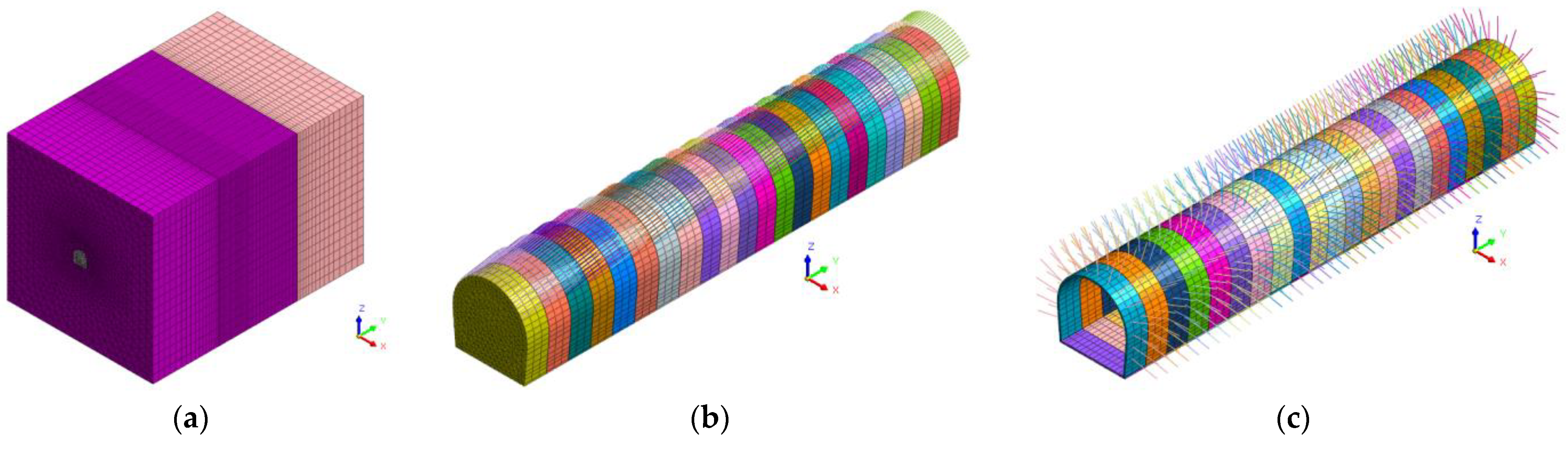
To evaluate the feasibility and rationality of the collapse treatment method for surrounding rock, a three-dimensional finite element model (see
Figure 15) was established based on the excavation and support conditions of the tunnel at the mileage from K79 + 900 to K78 + 779. In the model, surrounding rock, shotcrete, and secondary lining structures were simulated using 3-D solid element elements. Advanced small conduits and anchors were simulated using rod elements. Steel arches were simulated using beam elements. The mesh model contained 265,508 grid nodes and 142,612 elements.
Using the construction conditions and instability of the surrounding rock, as well as the stress estimation for the tunnel described in
Section 4, a numerical simulation was carried out. The calculated results are as follows:
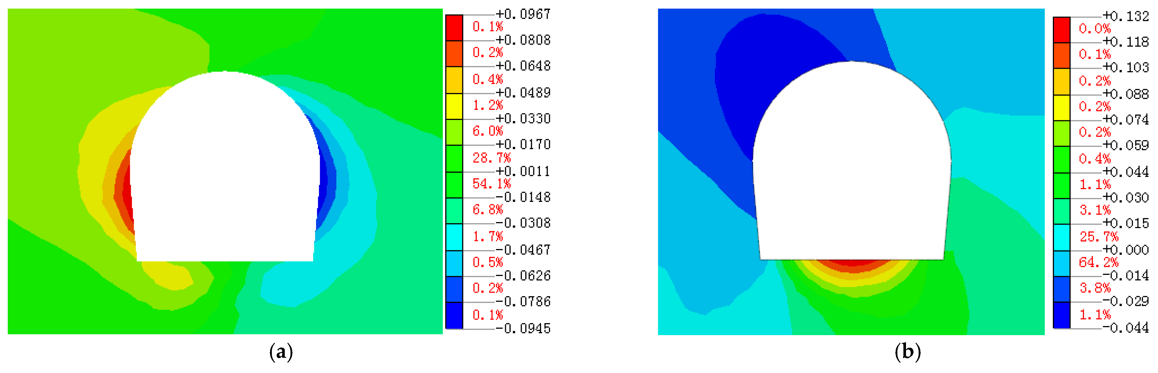
(1) Displacement distribution.
Figure 16 and
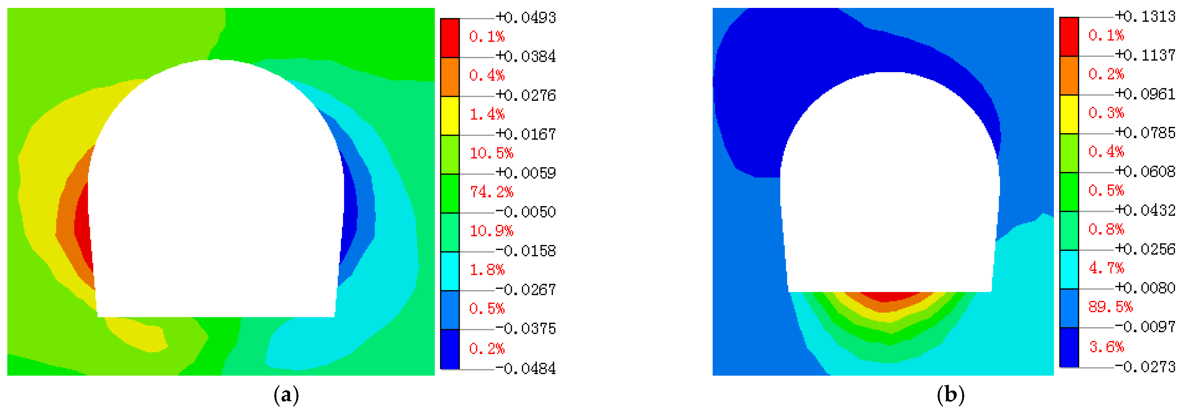
Figure 17 show the distribution characteristics of the displacement field after tunnel excavation with untimely initial support and with timely initial support, respectively. In the case of untimely support, the maximum horizontal displacement at the tunnel sidewall can reach 96.7 mm, and the maximum settlement at the top arch is 44.0 mm. At this time, the soft rock is extremely vulnerable to damage. However, with timely support, the maximum horizontal displacement at the tunnel sidewall can reach 49.3 mm, and the maximum settlement at the top arch is 27.3 mm.
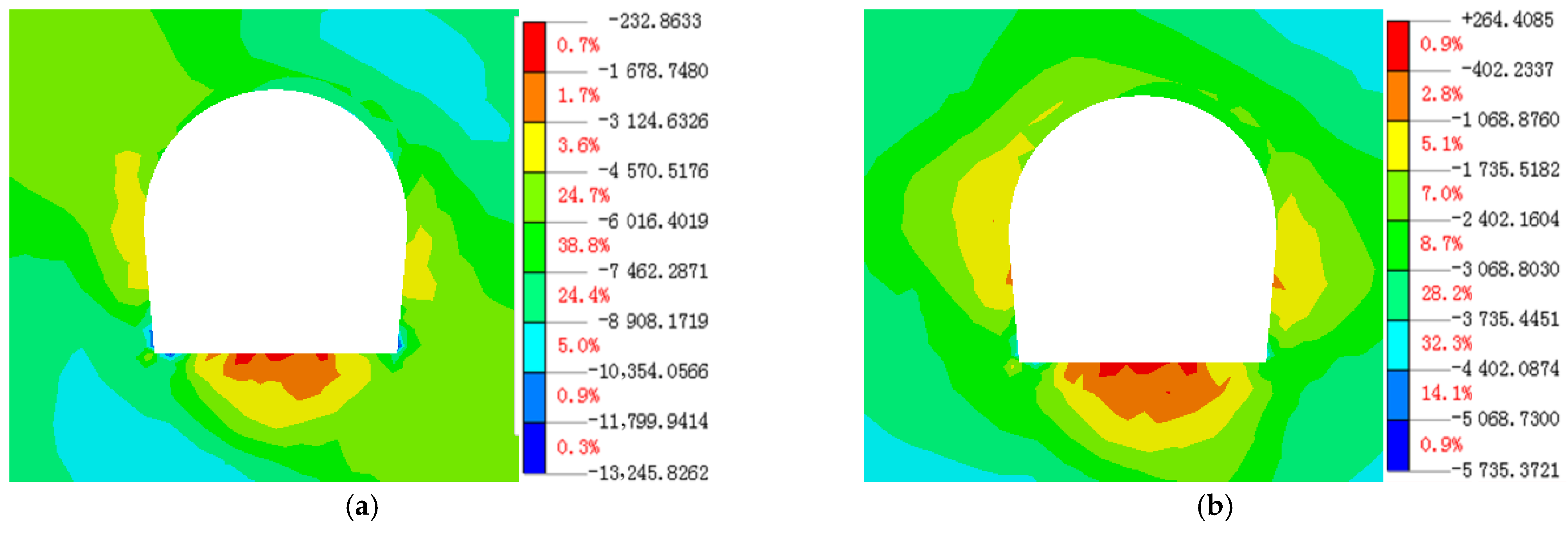
(2) In-stress stress distribution.
Figure 18 shows the distribution characteristics of the first and third principal stresses after tunnel excavation. It can be seen that there is a phenomenon of stress concentration in the local area around the tunnel (the intersection of the arch foot and side wall with the bottom plate), and the stress concentration is mainly located in the left arch shoulder and side wall. The above results are basically consistent with the on-site failure phenomenon (see
Figure 13), which are in good agreement with the inversion results in
Section 4. Furthermore, the values of the major principal compressive stress and third principal stress lie in the ranges −0.23 to −13.2 and 0.26 to −5.74 MPa, respectively.
5.4. Discussion
An in-depth analysis of the failure mechanism of surrounding rock during tunnel excavation at the mileage from K79 + 900 to K78 + 779 was carried out using a combination of the monitoring data, interpretation of rock failure characteristics, treatment measures for rock failure, and numerical simulations of the construction process and characteristics of the rock mass. We believe that the internal cause for the failure of the surrounding rock after the tunnel excavation was the fragmentation of rock mass, soft lithology, and the formation of sliding blocks due to the cutting of the structural plane. The external cause was improper construction and untimely initial support. After the tunnel excavation, it is not timely to carry out pre-grouting with advanced small conduit, bolting, and shotcreting support on the face of the tunnel, which results in unloading deformation of the surrounding rock. Then, plastic deformation occurs when encountering water, causing sliding damage to the side walls and arches. Further analysis showed that the sliding of the rock mass and the weakening of the mechanical properties of the structural plane caused a further adjustment of the stress field in the surrounding rock. In turn, the adjusted stress field led to further deformation of the structural plane. The complex interaction between the evolution of the rock mass structure and the adjustment of the stress field made the deformation of the surrounding rock exhibit certain time-effect characteristics, which was consistent with the maximum deformation of 10 mm/day observed during the tunnel excavation.
It can be concluded that for Class IV rock masses with fractured rock and relatively soft lithology, the failure of surrounding rock is more sensitive to the intensity of rock excavation disturbance. Therefore, in the subsequent construction process, the initial support measures such as adding an advanced small conduit with a diameter of 42 mm should be conducted at the face of the surrounding rock soon after the excavation. Meanwhile, the timely use of C20 sprayed concrete backfilling for collapsed areas should also be carried out. In that case, the impact of tunnel excavation on the stability of surrounding rock can be significantly reduced. Both the monitoring and numerical simulation indicated that during subsequent tunnel excavation, the stability of the surrounding rock was good, and the effectiveness of support measures was reasonably verified.
6. Conclusions
The contribution of this paper is the proposal of a method for in situ stress estimation of super-long and deep-buried tunnels based on multivariate information integration. The prominent features of this method include selecting the effectiveness and representativeness of the stress measurement data, identifying the failure phenomenon in surrounding rock during tunnel excavation, and verifying the results of the in situ stress inversion using multiple information types such as incomplete measurement data and on-site failure characteristics of the surrounding rock. This method was used to estimate the in situ stress in the sections of the super-long and deep-buried tunnel project in Qinling. Also, the failure mechanism and treatment measures of the surrounding rock are discussed. The main findings are as follows:
(1) The magnitude of the in situ stress near the axis of the Qinling water conveyance tunnel increased with the burial depth. The magnitude of the maximum principal stress was as high as 52.65 MPa, and the orientation of the maximum horizontal principal stress was mainly NW–EW.
(2) There were significant differences in the stress state along the deep-buried tunnel. When the burial depth of the tunnel was less than 1000 m, the in situ stress field at the tunnel elevation was mainly horizontal, that is, σH > σZ > σh. When the burial depth of the tunnel was greater than 1000 m, the maximum principal stress at the tunnel elevation was primarily owing to its own weight, that is, σZ > σH > σh.
(3) Compared with other areas, the fault zone and adjacent areas showed evident stress release characteristics, and the maximum horizontal principal stress direction also underwent a certain deviation. Furthermore, the fault and its surroundings showed that the vertical principal stress of rock mass was greater than that of the maximum horizontal principal stress, that is, σZ > σH > σh.
(4) The tunnel section from K79 + 900 to K78 + 779 of tunnel mileage collapsed in numerous locations during the construction process. The research showed that the initial support measures such as adding an advanced small conduit with a diameter of 42 mm should be conducted at the face of the fourth grade of surrounding rock soon after the excavation. The deformation of the surrounding rock after support will be significantly reduced, which will satisfy the construction safety requirements.
However, current in situ stress studies in underground engineering are mainly focused on the in situ stress field around deep hard rocks rather than soft rock tunnels. The in situ stress test method and theoretical verification near the large-deformation tunnel of soft rock are not yet mature and require further exploration.


 , green square
  , and blue diamond
  stand for the unit vector
of the orientation of the maximum, intermediate, and minimum principal
stresses, respectively (same as below). The three numbers behind Sigma (i.e.,
Sigma1, Sigma2, and Sigma3) stand for the principal stress values, azimuth, and
dip angles, respectively. It can be concluded that the long axial direction of the
stress ellipse is inclined to the upper (or lower) reach of the river valley on
the XY (or YZ) plane. On the XZ plane, the long axial direction is inclined to
the inside mountain. Similarly, the projection features of the stresses at
other testing points can also be interpreted.
stand for the unit vector
of the orientation of the maximum, intermediate, and minimum principal
stresses, respectively (same as below). The three numbers behind Sigma (i.e.,
Sigma1, Sigma2, and Sigma3) stand for the principal stress values, azimuth, and
dip angles, respectively. It can be concluded that the long axial direction of the
stress ellipse is inclined to the upper (or lower) reach of the river valley on
the XY (or YZ) plane. On the XZ plane, the long axial direction is inclined to
the inside mountain. Similarly, the projection features of the stresses at
other testing points can also be interpreted.


