Article

Study on the Seismic Response Characteristics of Shield Tunnels with Different General Segment Assembly Methods and Widths

1
School of Civil Engineering, Chang’an University, Xi’an 710064, China
2
School of Civil and Transportation Engineering, Ningbo University of Technology, Ningbo 315211, China
3
School of Faculty of Architectural, Civil Engineering and Environment, Ningbo University, Ningbo 315211, China
*
Author to whom correspondence should be addressed.
Buildings 2023, 13(8), 2039; https://doi.org/10.3390/buildings13082039
Submission received: 9 July 2023 / Revised: 3 August 2023 / Accepted: 8 August 2023 / Published: 10 August 2023

Abstract

:
Shield tunnels assembled with general ring segments are widely used in urban areas. Segment assembly methods and widths cause changes in the mechanical properties of the structure and influence the seismic response of shield tunnels. To investigate the influence of the assembly method and width of the general ring segment on the seismic performance of a shield tunnel, a three-dimensional refined soil–structure dynamic interaction finite element model of the shield tunnel was established based on ABAQUS, and the mechanical response and joint deformation of the general ring lining under seismic loads were studied. The simulation results show the following: (i) The overall deformation of the tunnel lining is not significantly affected by the assembly method, and the difference is only 5.24% under a 0.4 g earthquake. (ii) The seismic responses of general ring tunnels with different assembly methods are quite different, and the mechanical properties of the shield tunnel assembled with the straight assembly method are better than those of the shield tunnel assembled with staggered joints, but the deformation of the structure is larger. Under the action of a 0.1 g earthquake, the radial force, circumferential force, and bending moment of the staggered 90° assembly tunnel are respectively reduced by 13.6%, 11.1%, and 17.8% compared with the staggered 45° assembly structure, but the maximum intra-opening deformation increases by 0.19, 0.58, and 2.4 mm, respectively. (iii) The internal force distribution of the bolts is controlled by the deformation of the joint; compared with the CF90 and TF assembled tunnels, the mechanical properties and deformation characteristics of the CF45 and CF90 assembled tunnels are more reasonable. (iv) The extrados and intrados joint opening deformation and shear dislocation of the 1.2 m wide general ring segment under the staggered assembly increase by 1.2 mm and 1.03 mm, respectively, compared with the 1.5 m wide segment, while the radial force, circumferential force, and bending moment are reduced by 24.4%, 36.5%, and 41.7%, respectively, indicating that the seismic performance of the shield tunnel with a segment width of 1.5 m is better than that of the shield tunnel with a width of 1.2 m.

1. Introduction

With the rapid development of urban scale and economic construction and the rapid growth in population in metropolitan areas, the rapid transit system, built underground, has become an important tool of transportation, and subways have become the main basic transportation facilities in many cities to alleviate surface traffic saturation [1]. The area involved in the construction of rail transit in mainland China exceeded 9000 km at the end of 2021 [2]. The tunnel, as a kind of underground structure, is mainly affected by interaction with the surrounding soil during the action of an earthquake, while the load on the aboveground structures mainly comes from the inertial force generated by acceleration. There are differences in the mechanisms of earthquake damage between tunnel and aboveground structures. In general, metro shield tunnels have better seismic performance as a result of the interaction of the surrounding soil [3]. Thus, researchers have long thought that subways are less threatened by earthquakes. With the development of underground structures, more and more cases of underground structures being damaged by earthquakes have been paid attention to [4,5]. The seismic performance of underground structures has attracted the attention of more and more scholars as the views of people on the safety of underground structures have gradually changed. Situated at the intersection of the world’s two major seismic belts, the Pacific and the Eurasian, China is a country with frequent earthquakes, and most of the cities are located in or close to earthquake zones. At the same time, most of the extensive and complex subway systems that China has built are in large cities. In previous seismic disasters, including the 2008 Wenchuan Earthquake [6], the 1995 Kobe Earthquake in Japan [7], and the 1999 Chi-chi earthquake [8], it was observed that the tunnel lining was damaged to varying degrees.
Most of the coastal cities in southeast China have soft-soil tunnels, which have a low modulus of elasticity and poor soil quality compared with mountain tunnels. This is of central importance for seismic design in the case of metro systems, considering their significance for life safety and economy and that they are generally more vulnerable in soft-soil ground conditions [9]. With regard to the seismic resistance of shield tunnels in areas with soft soil, researchers have conducted a range of investigations, mainly focusing on the dynamic response of tunnel structures under complex soft-soil ground conditions with different earthquake intensities and site conditions and the corresponding seismic design measures [10,11,12]. However, the tunnel lining structure is simplified to a homogeneous circumferential ring in the above study, only the overall performance of the segment ring is taken into account, and the weak link of the shield tunnel connection is not taken into account, which is somewhat different from the actual structure. In fact, prefabricated segments were used in the construction of the tunnel and were bolted together on site, and the forces of the segment blocks are transmitted through the joint bolts under seismic loading, leading to changes in the mechanical failure mechanism of the shield tunnel [13], which have a significant impact on the overall seismic performance and dynamic characteristics of the tunnel [14]. Segment joints are also a vulnerable part of the structure when subjected to seismic loads, which will cause major deterioration of the structure in forms such as lining cracks, misaligned segment joints, and water leakage under the action of an earthquake [15]. Some scholars are now studying the effect of the discontinuity of shield tunnel tube joints on the seismic performance of shield tunnels [16], showing that the presence of joints makes a large difference in the internal force distribution and deformation at the joints of shield tunnels with the homogeneous circular ring model, leading to the redistribution of internal forces and deformation. The general ring segment is increasingly used in the construction of urban subways and large sections of underwater shield tunnels due to its advantages of great versatility, high assembly efficiency, accurate line control, and easy deviation correction [17], and the existing shield tunnel segment ring assembly method includes straight assembly and staggered assembly. Except for some soft ground represented by Shanghai, China, where the straight joint assembly method is used, most cities in China use the staggered assembly method [18]. The overall stiffness of a staggered assembly segmental structure is higher than that of a straight-assembly structure, and the deformation is also relatively small. Studies, including the model test and numerical simulation, have shown that the assembly method of general ring segments has a significant influence on the development of the internal force and deformation of shield tunnels [19,20,21,22]. Wang [23] studied the influence of a change in tunnel diameter on the performance of the joints and the stress state of the concrete, and the change in tunnel diameter was proposed as an evaluation parameter to estimate the performance of soft-soil tunnel structures. Liu [6,24] studied through a full-scale experiment that the failure mode of straight assembly depends on the bolt structure performance of the longitudinal joint, while staggered assembly is influenced by interaction between the rings. However, most of the above studies have focused on the influence of different segment assembly modes on the deformation development and failure process of general ring segments under static loading. The failure mechanism of the underground structure due to soil interaction is more complicated, but few studies have focused on the dynamic response of segment ring assembly methods to tunnel structures under dynamic loads such as earthquake loads, train vibrations, etc. Zhao [25] carried out seismic analysis on a shield tunnel in a soft-soil area and simulated an earthquake disaster affecting the shield tunnel using the ABAQUS three-dimensional discontinuous model. The simulation results accurately reproduced the mechanical characteristics of the segments and joints. Wang [26] established a staggered assembly general ring tunnel model to study the effects of the staggered assembly method and the straight assembly method on the amount of longitudinal joint tensioning and the damage law of the internal support of a shield tunnel. Gou [27] investigated the adaptability of the staggered assembly method and the direct assembly method for shield tunneling in ground fissures in Xi’an, China. Chen [28] used a beam spring model to investigate the seismic performance of a tunnel by using the reactive displacement method, and the results showed that the assembly angle has a significant effect on the internal forces of the tunnel structure. Zhang [29] mainly investigated the effect of the position of the capping block on the internal force of a segmental tunnel under a seismic wave.
In summary, many results have been obtained regarding the seismic response of shielded tunnels using the staggered assembly method, while the research on the seismic performance of shield tunnels constructed with different assembly methods mainly focuses on the structural mechanical properties. The joint deformation laws and mechanical behavior at the joints caused by different assembly methods of general ring segments under different seismic intensities are less involved, and the analysis of the effect of the width of the general ring segment is also less involved. According to this, a method based on dynamic time history analysis is adopted in the present study, and a discontinuous three-dimensional surrounding rock–structure interaction model of shield tube sheet joints was established. Ningbo Railway Transit Line 6 was selected as the engineering background, and the EI-Centro seismic wave was selected for the time history response analysis of the shield tunnel. The changes in the lining internal force, joint deformation, and bolt internal force of segments caused by different widths of general ring segments and assembling methods are studied. This paper provides a reference for the seismic design of shield tunnels in soft-soil areas.

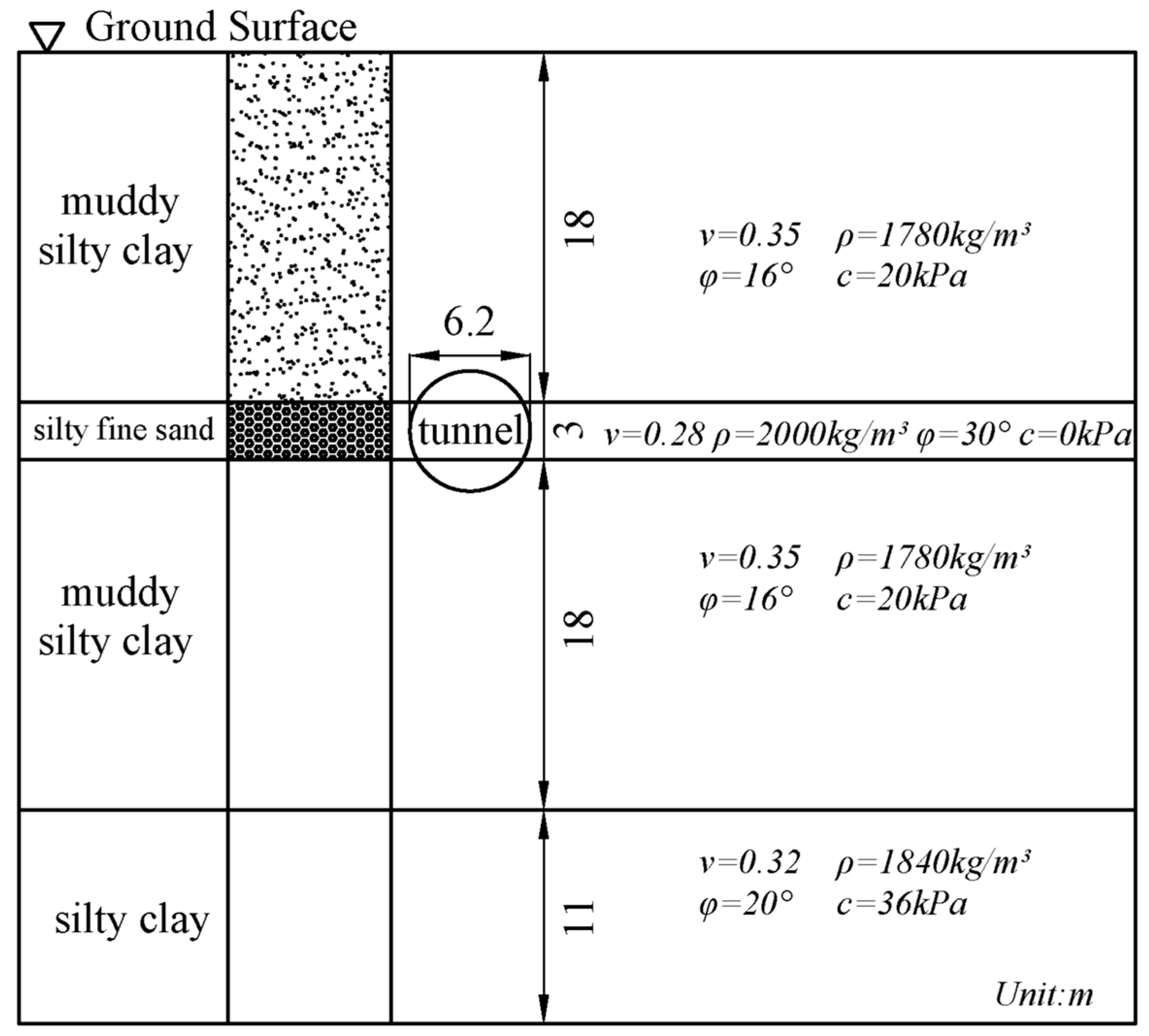
2. Engineering Research Background

Ningbo Railway Transit Line 6 is an east–west urban line with a total length of about 56 km, in which the overburden depth of the shield tunnel interval is 10~26 m, and this paper adopts the middle burial situation of the tunnel (burial depth 16.4 m). According to the geological situation traversed by Railway Transit Line 6, the shield tunnel was selected to pass through three complex soil layers of muddy silty clay, silty fine sand, and silty clay. The soil layers in which the tunnel is located are, from top to bottom, muddy silty clay, silty fine sand, muddy silty clay, and silty clay. The shield tunnel structure is located in an area with a wide range of muddy silty clay and sandy soil, and the top and bottom of the arch are partially in soft soils, while near the waist of the arch is sandy soil, and the soft layers are in close contact with the middle hard layer. Figure 1 shows the soil profile and location of the tunnel in this example.

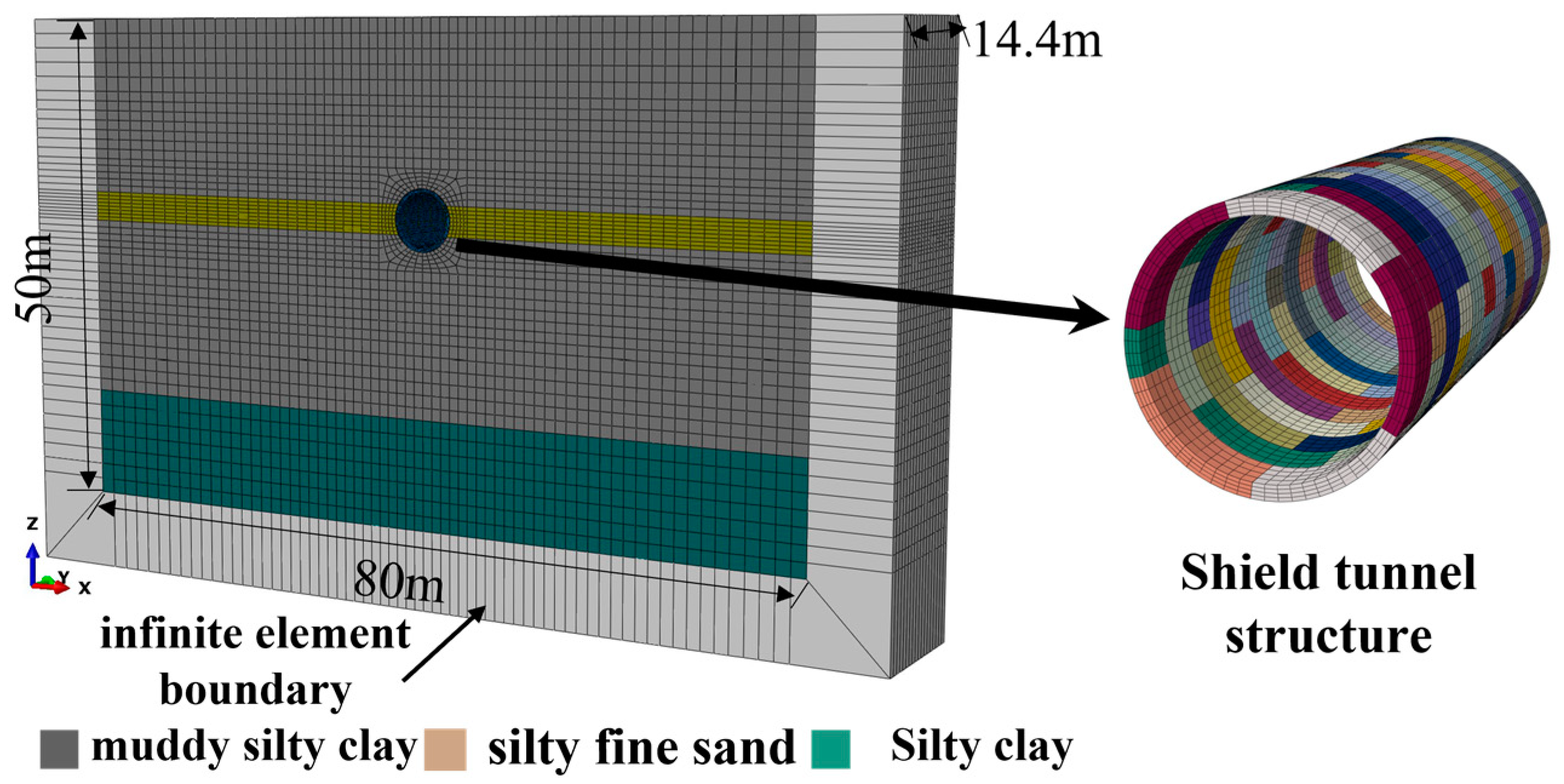
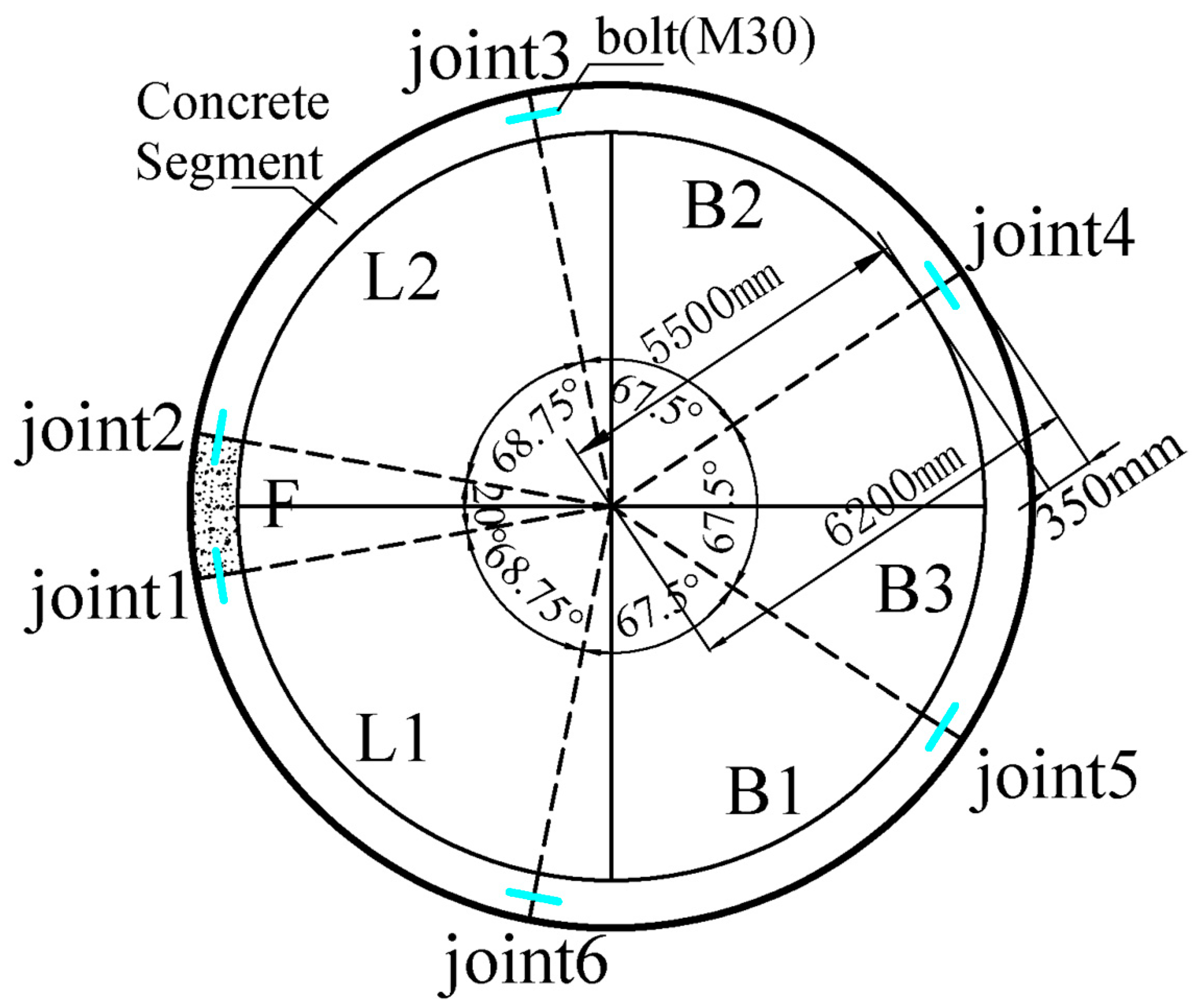
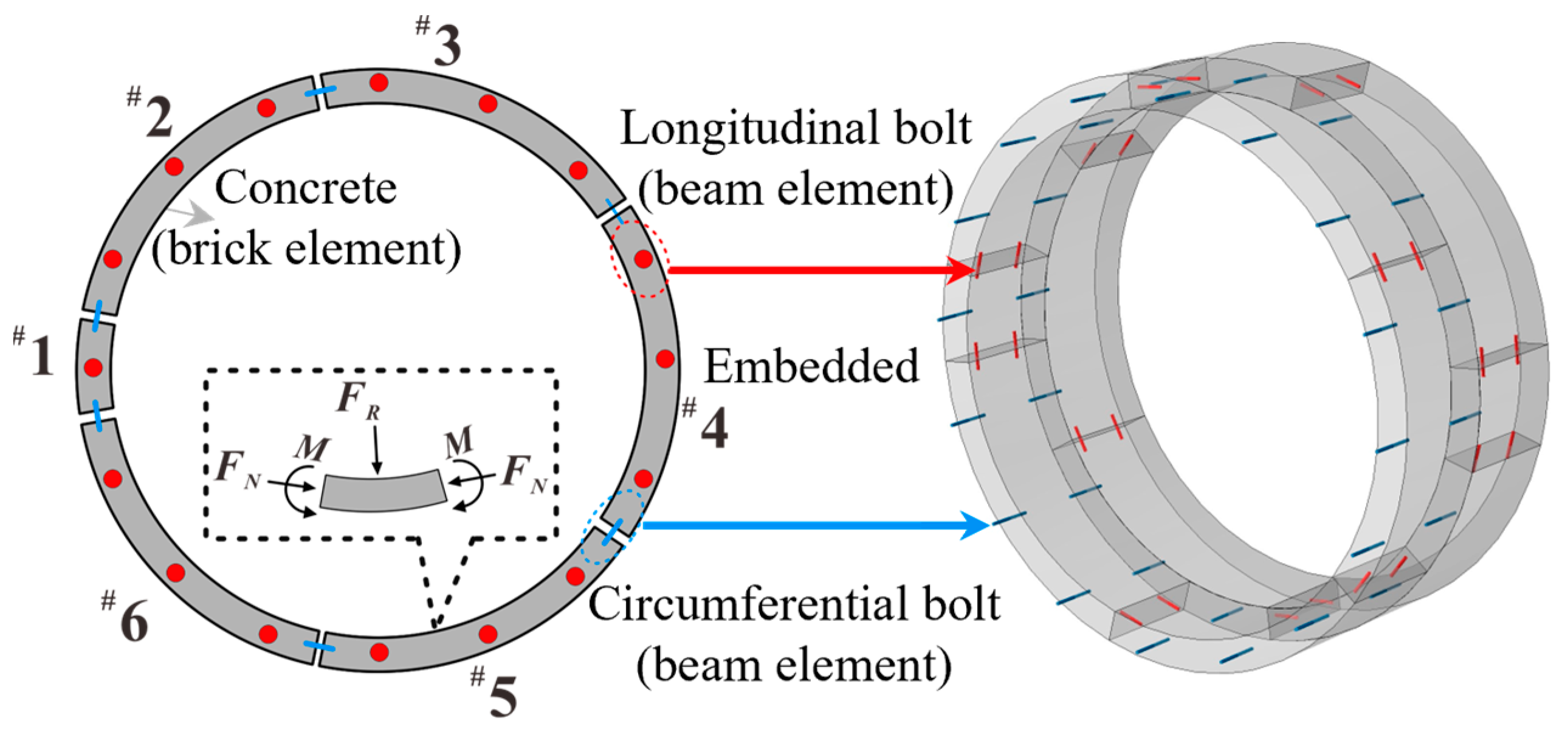
3. Numerical Model of Soil–Shield Tunnel Interaction

Based on the ABAQUS FEA simulation platform, a shield-segment three-dimensional discontinuous-contact finite–infinite element coupling model to analyze the seismic response of shield tunnels was constructed. The size of the model was selected according to the properties of the layered soil and the influence of the number of model elements on the calculation efficiency. Therefore, the size of the model is 80 m × 50 m × 14.4 m, and the buried depth of the center of the tunnel is 19.5 m. Considering the properties of some soft-soil layers are similar in the area where this project is located and the changes in parameters are minor, the soil layers are appropriately simplified based on the properties of the soil layers. The dynamic elastic modulus and dynamic shear modulus of the soil are converted from the weighted average shear wave velocity of each soil layer measured on site in the survey report. To ensure the accuracy and efficiency of dynamic calculation, the grid size of the soil layer model should be smaller than 1/10 to 1/8 of the minimum seismic wavelength [30]. The central soil grid size is 0.8 m, and the maximum size is 1.4 m to meet these conditions. There were 62,344 elements and 67,963 nodes in the finite element model developed; the dynamic calculation model is shown in Figure 2.
The outer radius of the tunnel segment ring is 6.2 m, the inner radius is 5.5 m, and the segment thickness is 0.35 m. It is assumed that the tunnel lining consists of six precast concrete segments made of C50 concrete, one capping block (F, 20° of the center of the circle), two adjacent blocks (L1, L2, circular angle 67.5°), and three standard blocks (B1, B2, circular angle 68.75°), as shown in Figure 3. The maximum width is 1218.6 mm, the minimum width is 1181.4 mm, and the average width is 1200 mm. There are certain bolted connections between different segment blocks and segment rings in the shield tunnel structure that reduce the overall structural stiffness of the shield tunnel and affect the internal force distribution and deformation of the shield tunnel. The circumferential joints of the tunnel ring were connected by two segment blocks with a pair of Grade M30 steel bolts. In addition, the longitudinal tunnel joint was connected by two rings through a number of sixteen Grade M30 steel bolts evenly distributed, as shown in Figure 4. The linear brick solid elements are used to model soils, using reduced integration (C3D8R) to reasonably facilitate the computational efficiency of soil behavior [31].
The T3D2 truss element was used to simulate the internal reinforcement of the tunnel segment and embedded in the concrete segment to realize the mechanical properties of reinforced concrete, and the shield tunnel was modeled using the C3D8R linear brick element with an embedded linear beam element B31. The concrete segment structure and tunnel internal reinforcement adopt the elastic constitutive model; the beam element corresponding to the steel bolt location adopts the bifold reinforcement model; and the Mohr–Coulomb constitutive model was used to simulate the surrounding soil layer. The physical and mechanical performance of each soil layer and shield tunnel is shown in Table 1.

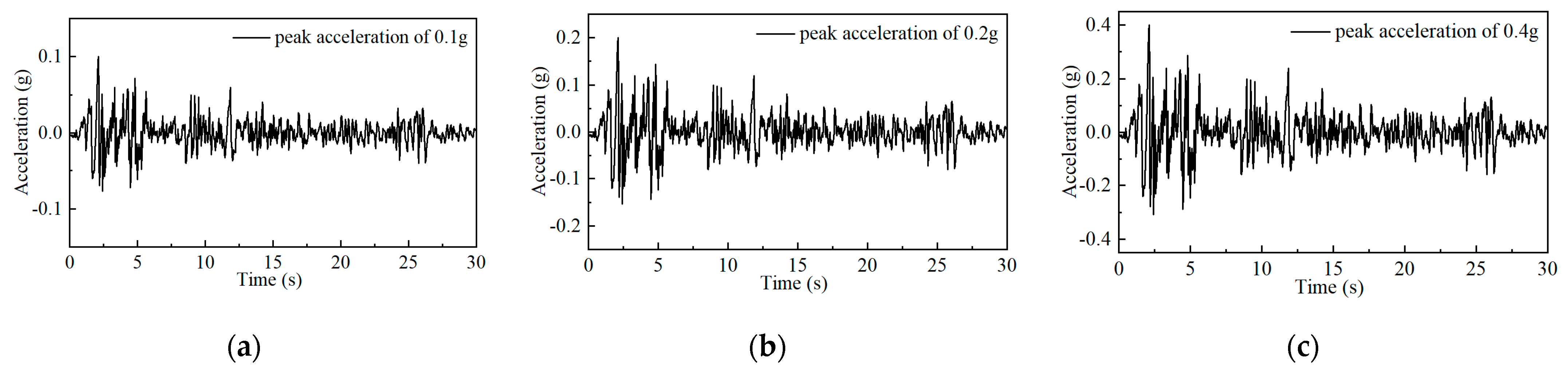
4. Surrounding Rock–Tunnel Interaction, Boundary Conditions, and Input Motions

To consider the soil–tunnel contact relationship at the interface, the shield tunnel segments and soil are usually set as interaction contact surfaces to account for contact discontinuity between the shield tunnel and the surrounding soil medium and any possible compression, separation, or sliding of these structural components from the surrounding soil under seismic excitation [32]. Contact surfaces consisting of master and slave surfaces were defined to implement the contact pair method. In this paper, the soil deposit surface around the tunnel was considered as the master surface, and the outer surface of the shield tunnel segment was regarded as the slave surface. Additionally, the contact between different tunnel segment blocks needs to be taken into consideration, and there is no requirement to purposefully distinguish the master and slave surfaces between tunnel segments because the material and mesh of the master and slave surfaces are identical. To simulate the interaction in the normal direction of the surfaces, the hard-contact algorithm was used so that pressure can only be transmitted when the master and slave surfaces are in contact with each other. The tangential behavior of the interfaces followed the classical frictional contact model, and according to previous studies, the coefficient of friction can be taken as μ = 0.5 [33]. CIN3D8 (eight-node linear unidirectional infinite brick) elements were used to describe the infinite area, which allowed the energy reflected by the seismic wave on the truncation boundary to be absorbed by the model. The role of infinite element boundaries is different in static analysis and dynamic analysis [14]. Therefore, the following steps were used to perform static–dynamic boundary transformation and seismic response analysis: during the static analysis step, the gravity load was applied, the static boundary condition was that the fixed boundary was used in all directions at the bottom of the soil deposit, and the roller boundary, which allowed vertical displacement and prevented horizontal displacement, was used on the side boundary to balance the initial stress of the model to obtain the static stress field of the soil in the static analysis, and the method of model change was used to simulate the excavation process and to obtain the initial stress field after excavation. However, during the seismic analysis, when the seismic motion was input, the original static roller boundaries at the side boundaries were replaced by dynamic infinite element boundaries (one-way CIN3D8 element dynamic infinite element boundaries) [31]. In this study, the El Centro wave in the United States was selected as the input seismic wave, and the acceleration peaks were adjusted to 0.1 g, 0.2 g, and 0.4 g, respectively. The acceleration time history of the seismic wave after peak adjustment is shown in Figure 5. The effective duration takes the first 15 s before reaching 10% of the peak acceleration, and the processed seismic waves were imposed from the bottom boundary of the model.

5. Dynamic Response Characteristics of Shield Tunnel under Different Assembly Methods

In this section, the seismic responses of shield tunnels with four assembly methods during different seismic intensities (the peak accelerations of the input seismic motions are 0.1 g, 0.2 g, and 0.4 g, respectively) are analyzed from the aspects of tunnel internal force and deformation response and the mechanical behaviors of segmental joints.

5.1. FEM of Shield Tunnel under Different Assembly Methods

In order to study the influence of the general ring assembly methods on the seismic response of the shield tunnel structure, four kinds of assembly methods were used: one straight assembly (TF) and three staggered joint assemblies (CF). The staggered joint assemblies were 22.5, 45, and 90 degrees along the central axis of the tunnel. The angles between two adjacent ring capping blocks were 45, 90, and 180 degrees, respectively, recorded as CF45, CF90, and CF180, respectively. The schematic diagram of the assembly method and the specific scheme are shown in Table 2.

5.2. Numerical Investigations and Discussions

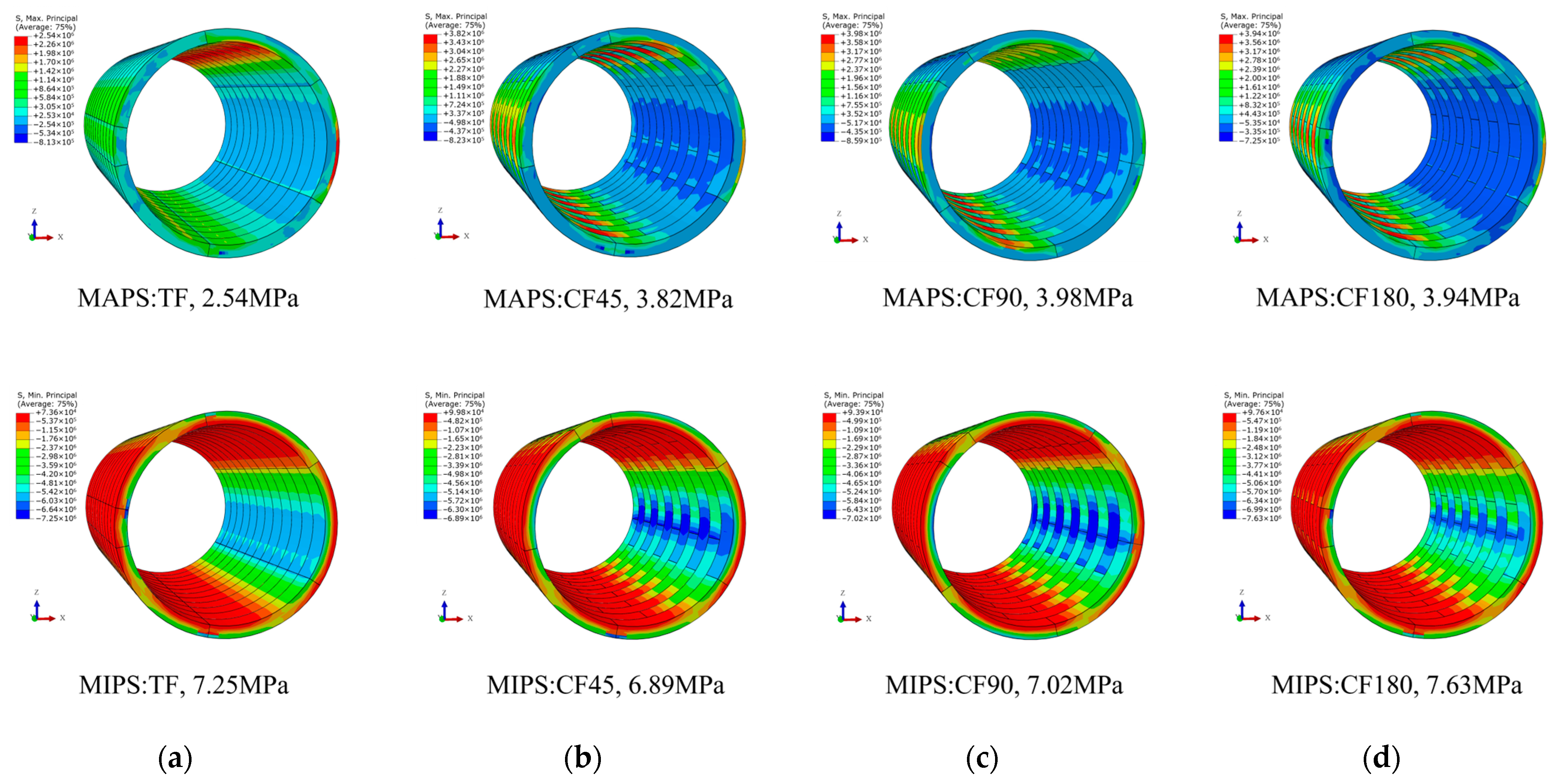
5.2.1. Deformation of Shield Tunnel Structure with Different Assembly Methods due to Seismic Loads

Shear deformation of the shield tunnel section is one of the important indicators reflecting the seismic response characteristics of the structure and should be considered. The shear deformations defined here are the ratio of the relative horizontal displacement between the top and bottom of the arch to the tunnel diameter. Figure 6 shows the influence of the assembly method on the shear deformation under different seismic loads. It can be seen that the shear deformation of the shield tunnel does not vary significantly depending on the assembly method, and the assembly method has little effect on the overall deformation of the structure. Under the action of an earthquake with 0.1 g peak acceleration, there is only a 0.03% difference between the shear deformation of condition CF90, which is the maximum, and that of condition TF, which is the minimum. The difference between the maximum of shear deformation (CF90) and the minimum (TF) under the action of 0.4 g seismic loading is 5.24%, indicating that the tunnel structure and the surrounding soil and seismic medium are moving simultaneously and that the overall deformation of the shield tunnel is controlled by the relative displacement of the surrounding soil, not by the assembly method.

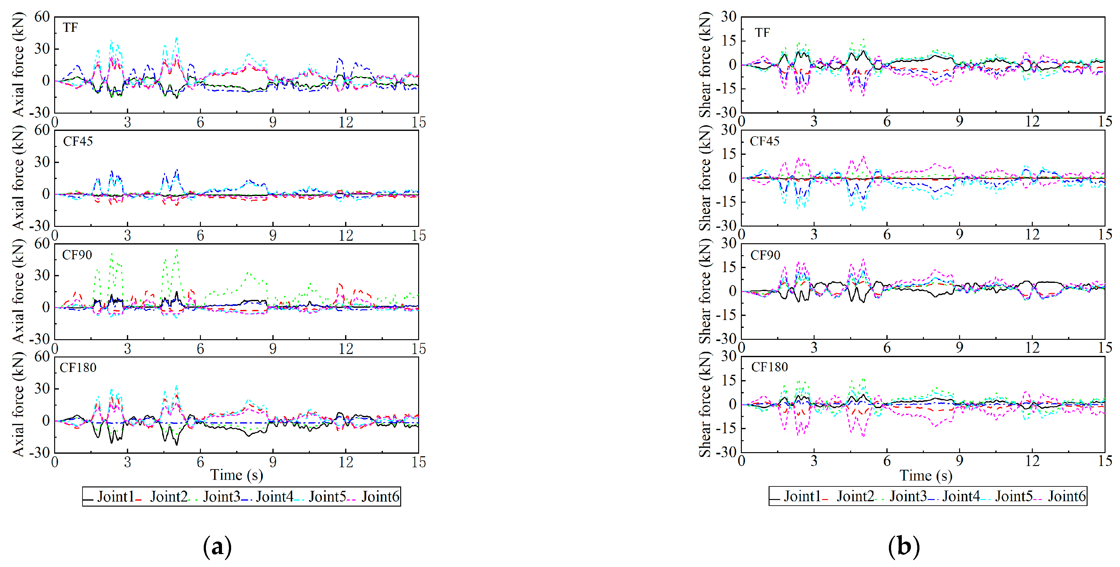
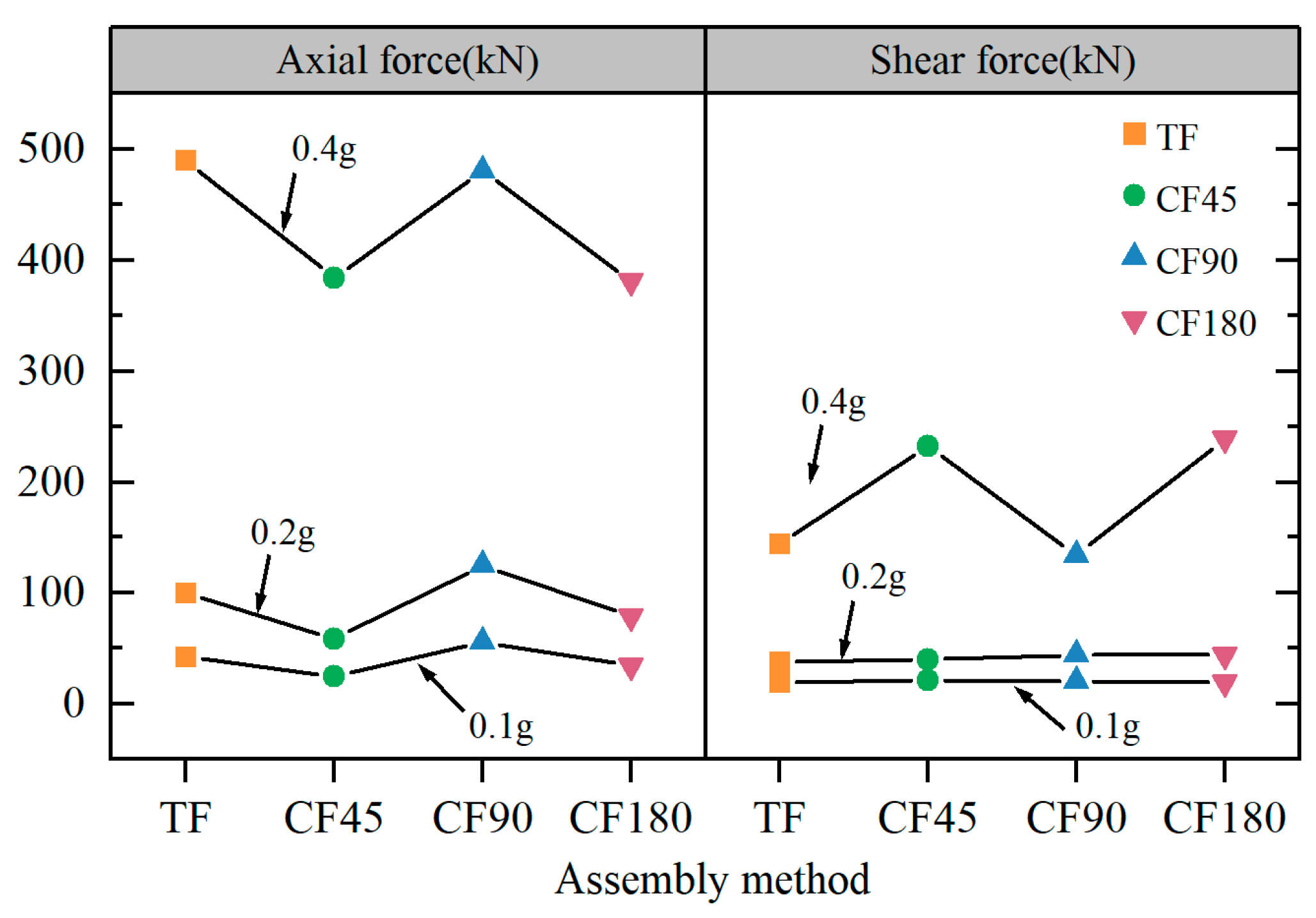
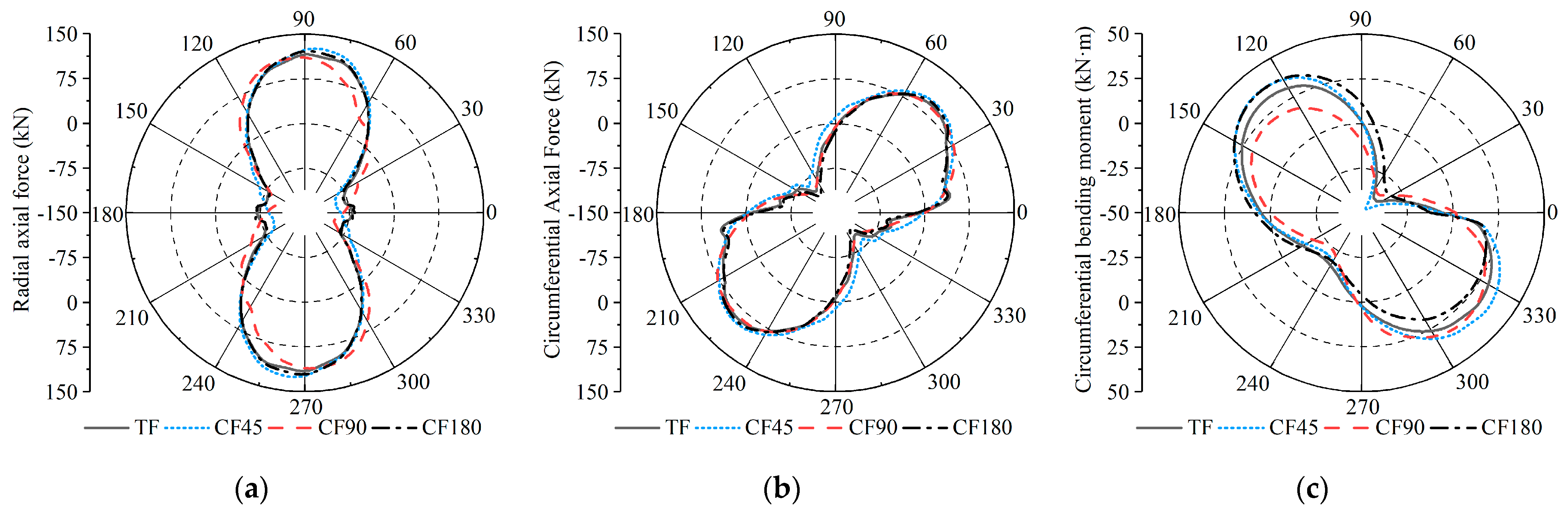
5.2.2. Mechanical Behavior of Shield Tunnel Joints under Different Assembly Methods

The phenomenon of earthquake damage to the structure of shield tunnels in the past indicates that despite the high strength of the tunnel section, the damage is slight, but the mechanical properties of the joints of the shield tunnel are relatively weak [34]. Therefore, the deformation indicator of segment joints was used to evaluate the seismic performance of shield tunnels. Figure 7 shows the time history curves of the extrados opening, intrados opening, and shear dislocation at each joint of the general ring segment under different assembly methods at 0.1 g seismic loading. It can be seen that due to the shear deformation caused by the relative displacement between the soil layers during the transmission of the seismic wave, the joints are compressed, opened, and displaced due to the relative slip and separation between the shield segments. The deformation of the segment joints is unevenly distributed, with some joints deforming heavily under tensile forces and others deforming poorly under compression. The time histories at the joint alternate between positive and negative, and the location of the peak joint deformation varies as the assembly method changes. As an illustration of the extrados opening, the maximum extrados opening joint deformation occurs at segment Joint 2 for the assembly methods TF and CF180, while that of CF45 and CF90 occurs at segment Joint 4. The different positions of the capping block also change due to an alteration in the assembly method, resulting in different degrees of joint deformation. The extrados joint opening of method TF is the maximum, which is 0.27 mm, the intrados joint opening of method CF90 is the maximum, which is 0.52 mm, and the shear dislocation of method CF45 is the maximum, which is 0.16 mm. Figure 8 shows the maximum deformation of the extrados opening, the intrados opening, and the shear dislocation of the shield tunnel segment joints in the four assembly methods under different seismic loadings. It can be seen that the joint deformations of the assembly methods CF45 and CF180 are relatively similar under 0.1 g and 0.2 g earthquakes. Compared with the minimum value of CF180, the maximum deformations of the CF90 assembly increased by 0.19, 0.55, and 2.6 mm, respectively, under the three seismic intensities. This is even higher than the assembly method TF, with lower overall stiffness. Meanwhile, the maximum joint opening deformations under the action of 0.4 g earthquakes of the TF and CF90 assembly methods significantly exceed the maximum limit values recommended by the Chinese Code for design of shield tunnel engineering (3 mm), while the joint deformations of the CF45 and CF180 staggered assembly methods are relatively close and still within the limit, which can ensure their safety and watertightness. The deformation of the segment joint is greatly affected by the position of the capping block, and it should be avoided that the location of the capping block is at the spandrel of the tunnel, as the deformation of the joint is greatly improved.
Deformation of the segment leads to the opening, compression, and dislocation of the joint, which affect the internal force distribution of the joint bolts. Figure 9 shows the time histories of the axial and shear forces of each joint bolt of the four general ring segment assembly structures under the action of a seismic wave with a peak value of acceleration of PGA = 0.1 g. It can be seen that the time histories of the axial and shear forces are basically consistent with the change law of the corresponding joint deformation. The position of the maximum axial force of the bolt corresponds to the maximum opening deformation of the joint, and the position of the maximum shear force of the bolt corresponds to the maximum dislocation of the joint, which further indicates that the internal force distribution of the bolts is controlled by the deformation of the joint. Figure 10 shows the peak axial and shear forces of the joint bolts in the four assembly methods under different seismic loadings. Using 0.1 g seismic loading as an example, the maximum bolt axial force of CF90 is 55 kN, which is 13 kN higher than the 42 kN obtained by using the straight assembly method, and comparing the other two staggered assembly methods, CF45 and CF180 increased by 31 kN and 21 kN, respectively. The shear force difference in the four assembly methods is relatively close under 0.1 g and 0.2 g earthquake action, which indicates that under this earthquake intensity, the difference in the assembly method of the general ring segment has negligible influence on the bolt shear force. However, under the action of a 0.4 g earthquake, the bolt shear force of the CF45 and CF180 assembly methods is obviously more developed than that of TF and CF90.
Figure 11 shows the internal force envelopes of shield tunnels with four assembly methods under the action of a seismic wave with a peak value of acceleration of 0.1 g (the direction of the internal forces of the segment is indicated in Figure 4). It can be seen that the distribution of internal force is not greatly affected by the assembly method, and the maximum circumferential internal force and maximum circumferential bending moment occur within the range of ±45° from the tunnel axis. The main reason for this is that the different assembly methods of the general ring segments change the stiffness of the shield tunnel structure, but the distribution of additional stresses on the segment structure caused by the same seismic wave and site conditions is the same. However, due to the change in joint position caused by the position of the capping block under different assembly methods, the structural stiffness of the ring joint is weakened, and the deformation of the joint under the earthquake causes the redistribution of the internal force value. The difference is mainly due to the difference in structural stiffness among the joints and segments caused by the assembly method, and low stiffness has better adaptability to deformation. In addition, due to the different positions of the capping blocks, the deformation of the segment joints under the earthquake is significantly different, and the release of internal forces at the joints is also an important reason for the difference in internal forces. The circumferential axial force and bending moment of the CF90 method are smaller to varying degrees near the capping blocks, which indicates that the assembly method has changed the numerical law of the internal force of the lining structure. The maximum internal force of the shield tunnel under different assembly methods is shown in Figure 12, taking a 0.1 g earthquake as an example under different assembly methods. The maximum radial axial force of CF45 is 126.9 kN, and the minimum of CF90 is 112.6 kN, with a difference of 13.6%; the maximum circumferential axial force of CF45 is 98.3 kN, and the minimum of CF90 is 88.2 kN, with a difference of 11.1%; and the maximum circumferential bending moment of CF45 is 38.3 kN·m, and the minimum of CF90 is 32.5 kN·m, with a difference of 17.8%. Meanwhile, as the intensity of the earthquake loading rises, the internal force envelope law changes little, but the difference is more significant.
Considering the structural stress characteristics and based on previous research experience [32], the maximum principal stress (MAPS) and the minimum principal stress (MIPS) were selected for stress characteristic analysis. MAPS is primarily used to evaluate the tensile failure location of the tunnel, while MIPS is primarily used to evaluate the compression failure location of the tunnel. Figure 13 shows nephograms of stress of each general segment assembly method under a small earthquake. In each assembly method, the MAPS of method CF90 is the maximum, which is 3.94 MPa; the MIPS of method CF180 is the maximum, which is 7.63 MPa. Under an earthquake intensity of 0.1 g, the segment structures for all assembly methods did not exceed the tensile and compressive damage limits of concrete, and the structure is in an elastic working state. Table 3 shows the MAPS and MIPS of four shield tunnel assembly methods under different earthquake action. With the increase in earthquake intensity, the MAPS and MIPS of the shield tunnel gradually increase, which is consistent with the seismic response law of general underground structures. In the same case, the MIPS of the tunnel structure changes in a small range, and the MAPS of the tunnel structure using the TF assembly method is smaller than those of the other three staggered assembly methods, which may be due to the lower stiffness.

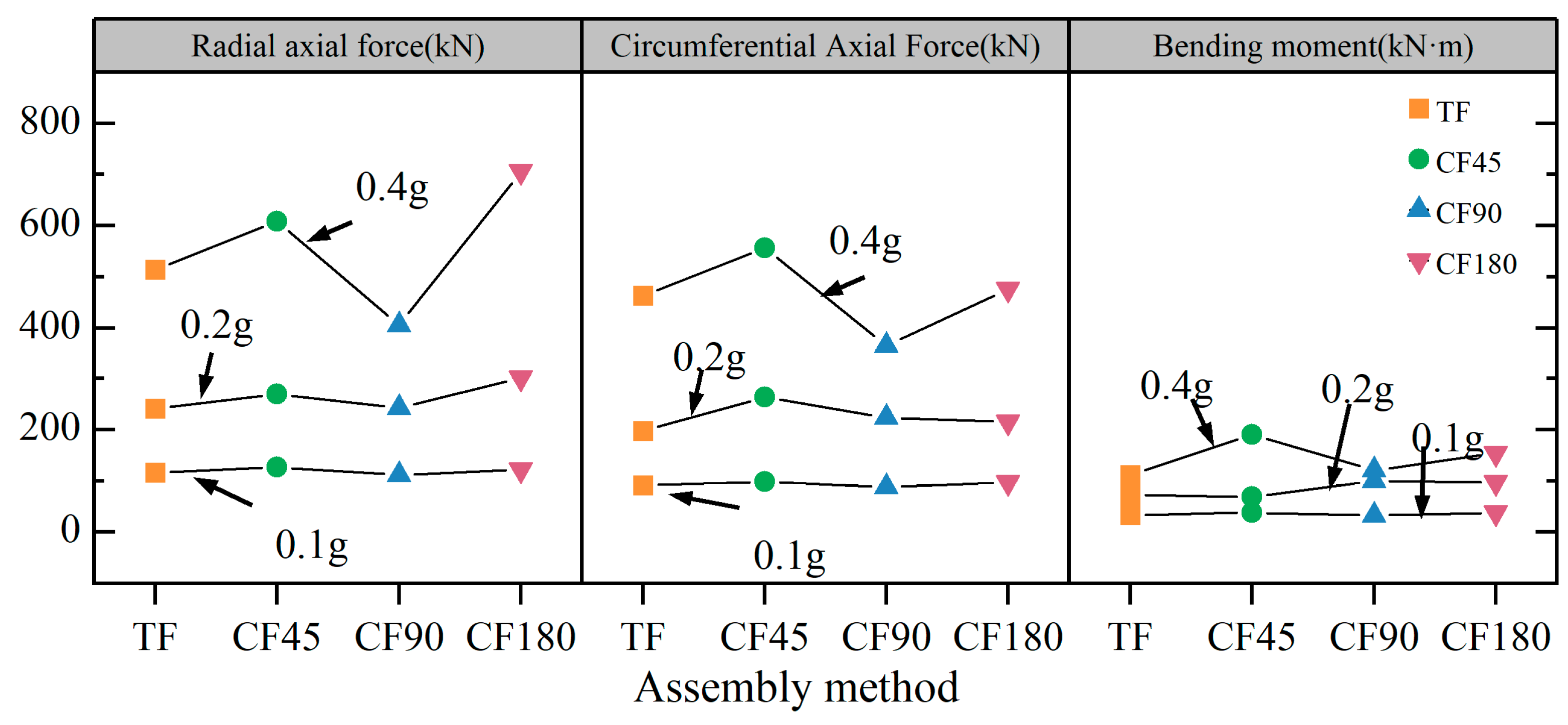
5.2.3. Evaluation and Discussion of Seismic Performance

Under the conditions of 0.1 g and 0.2 g earthquake loadings, the safety and watertight performance of the tunnel lining can be guaranteed. Table 4 summarizes the seismic performance analysis of the four general ring assembly methods under the action of 0.4 g earthquake conditions; the maximum joint deformation of CF90 and TF far exceeds the code limit, the maximum bolt stress exceeds the yield point, and the maximum stress variation is in a wide range. The seismic performance of the shield tunnels assembled using CF90 and TF cannot meet the design requirements. However, the mechanical properties and deformation characteristics of the tunnels assembled using CF45 and CF180 are more reasonable, and the tunnel structure is in a safe working condition. In summary, the seismic performance of the CF45 and CF180 assembled tunnels can meet safety and water resistance requirements.

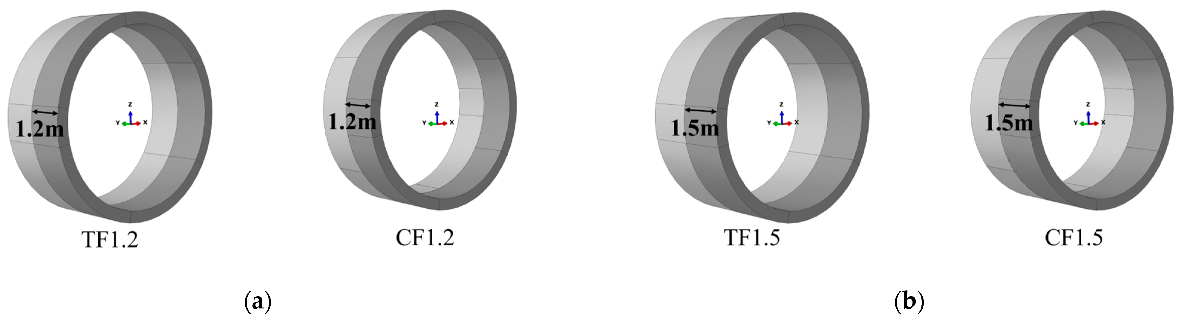
6. Dynamic Response Characteristics of Shield Tunnel under Different Segment Widths

The change in the segment width causes the overall stiffness of the shield tunnel to change, and the decrease in the width increases the discontinuity of the structure. In this section, general segments of different widths under two assembly methods are selected for analysis under the peak acceleration of 0.4 g earthquakes.

6.1. FEM of Shield Tunnel under Different Segment Widths

In order to study the influence of the width of the general ring segment on the seismic performance of the shield tunnel structure, two kinds of segment widths were used. General segments of 1.2 m and 1.5 m widths under the two assembly methods of straight and 180-degree assembly, recorded as TF1.2, CF1.2, and TF1.5, CF1.5, respectively, are shown in Figure 14.

6.2. Numerical Investigations and Discussions

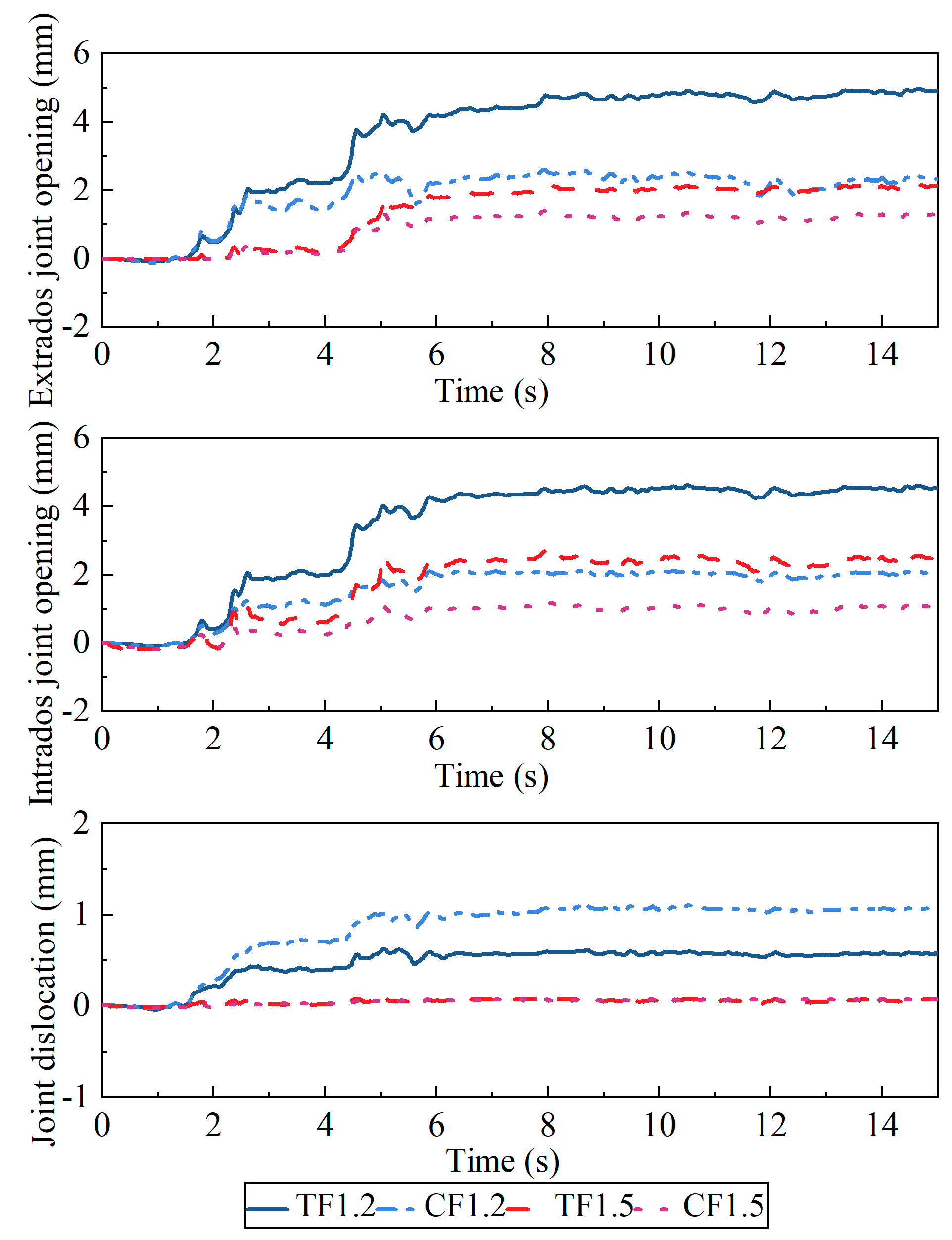
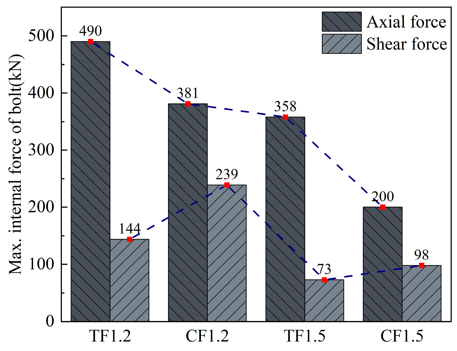
6.2.1. Mechanical Behavior of the Shield Tunnel Joints under Different Segment Widths

Figure 15 shows the time histories of the maximum joint deformation of the general ring segments with widths of 1.5 m and 1.2 m. The residual deformation of the structure is relatively large after the 0.4 g earthquake excitation; the large irreversible plastic deformation of the soil layer is the main reason for this. Meanwhile, the deformation of joints with a width of 1.5 m is significantly smaller than that of joints with a width of 1.2 m, which is mainly due to the integrity of the tunnel, structural rigidity, and resistance to deformation increasing with increasing segment width.
The maximum axial force and shear force of the shield tunnel joint bolts under different widths are shown in Figure 16. It can be seen that the internal force distribution of the joint bolts is still controlled by the deformation law of the joint. The bolt axial force of the condition TF1.2 is the maximum, which is 490 kN, and that of the condition CF1.5 is the minimum, which is 200 kN. The bolt shear force of the condition CF1.2 is the maximum, which is 239 kN, and that of the condition TF1.5 is the minimum, which is 73 kN. Meanwhile, the bolt axial and shear forces of the 1.5 m wide general ring tunnel are reduced compared with those of the 1.2 m wide ring whether the straight assembly method or staggered assembly method is used. The internal force of the bolt of TF1.2 exceeds the yield strength of 400 kN. According to the development law of the maximum axial force and shear force of bolts with different general ring segment widths, the strength of the 1.2 m wide segment connecting bolts should be increased accordingly to prevent possible damage.

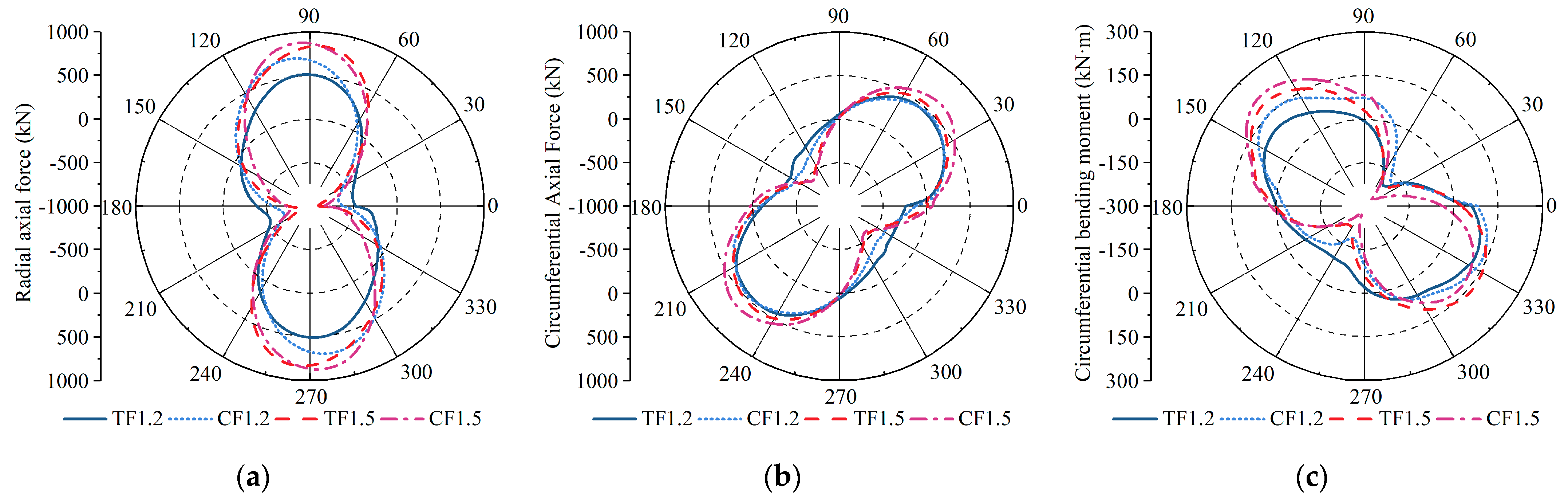
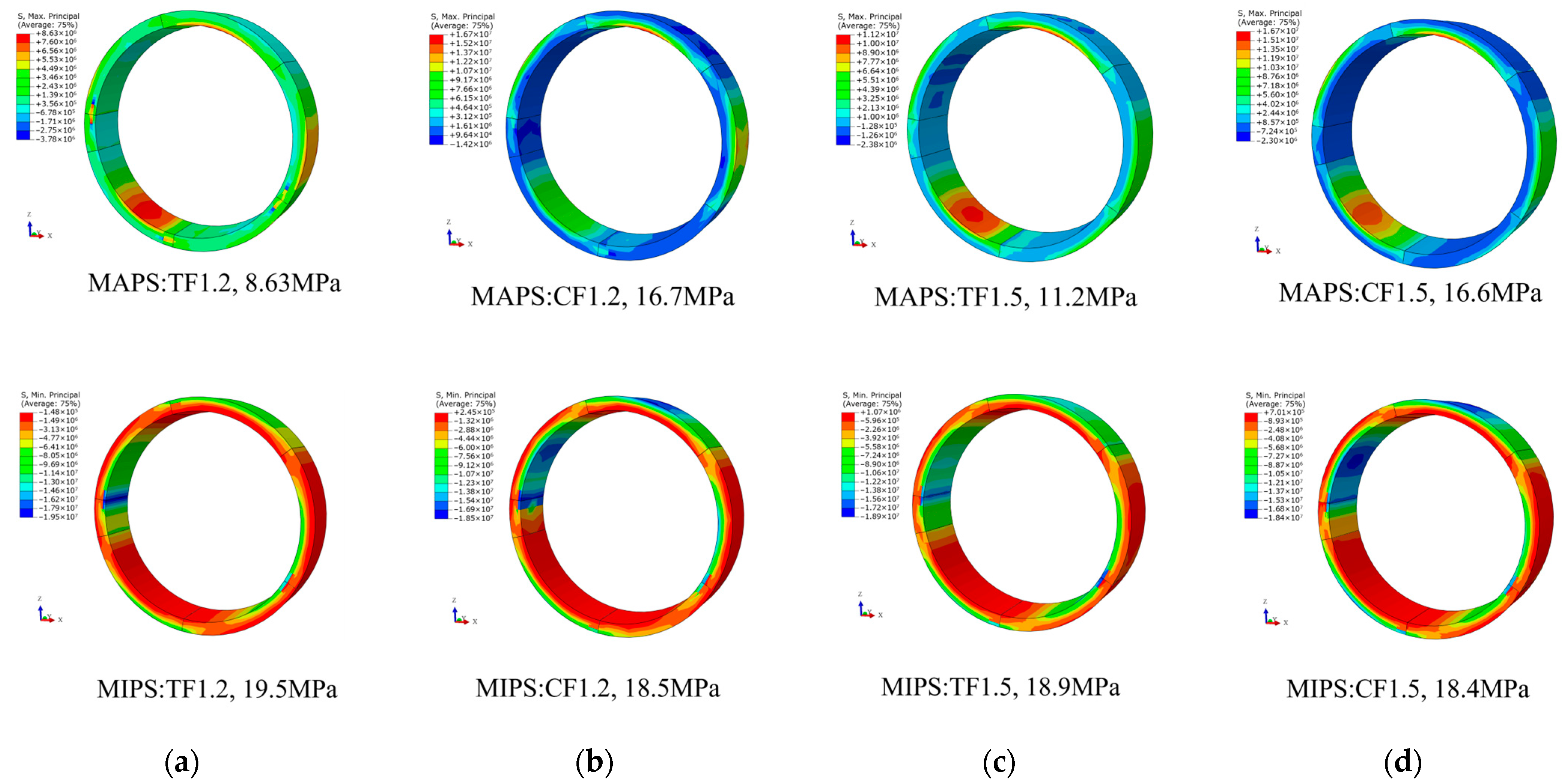
6.2.2. Mechanical Behavior of Segments under Different Segment Widths

Figure 17 shows the internal force envelope diagrams of two kinds of general segment width shield tunnels under the earthquake intensity of 0.4 g. It can still be seen that the internal forces of the lining in a straight assembly method are smaller than those of a staggered assembly method. Considering the internal force law of tunnels using the staggered assembly method under two kinds of width conditions as an example, the maximum radial axial force with a width of 1.5 m is 878.5 kN, and that with a width of 1.2 m is 705.8 kN; the maximum circumferential axial force with a width of 1.5 m is 649.6 kN, and that with a width of 1.2 m is 476.1 kN; the circumferential bending moment with a width of 1.5 m is 218.1 kN·m, and that with a width of 1.2 m is 154 kN·m. In terms of specific values, the radial axial force, circumferential axial force, and circumferential bending moment differ by 24%, 36.5%, and 41.7%, respectively, which means that the change in segment width has a significant influence on the mechanical properties of the tunnel structure. The main reason for this is that increasing the segment width can enhance the stiffness of the shield tunnel and reduce the discontinuity between the segment ring and the ring, increasing the overall stiffness of the structure and reducing the deformation capacity. Notably, the deformation of the structure is opposite to the law of the internal force: the joint deformation and bolt internal force of the 1.5 m wide segment are both reduced, but the internal force of the structure is significantly increased. Therefore, the need to determine how to coordinate the structural stiffness of the tunnel makes its internal force and deformation particularly important.
The stresses of each ring are approximately similar, so the cloud diagram of the MAPS and MIPS of the fifth ring of the shield tunnel change is given as shown in Figure 18. The maximum MAPS value for the CF1.2 operating condition is 16.7 MPa, and the minimum MAPS value for the TF1.2 operating condition is 8.63 MPa; the maximum MIPS value for the TF1.2 operating condition is 19.5 MPa, and the minimum MIPS value for the TF1.5 operating condition is 18.4 MPa. It can be seen that as the segment width increases, the MAPS of the segment ring under the staggered and straight assembly methods decreases with the increase in width, while the MIPS does not change significantly.

6.2.3. Analysis and Discussion of Seismic Performance

Table 5 summarizes the seismic performance evaluation of general ring tunnels of two widths under 0.4 g earthquake conditions. Except for TF1.2, the maximum joint deformations of TF1.2, TF1.5, and CF1.5 did not exceed the specification limit, and the maximum bolt stress was less than the yield point. The mechanical properties and overall stiffness of the tunnel are enhanced with the increase in the width of the general segment ring, and the deformation and internal force characteristics of the segment joints are significantly improved. To sum up, the segment width should be appropriately increased to reduce the discontinuity between the segment rings to increase the seismic resistance of the tunnel while ensuring the construction requirements are met.

7. Conclusions

In this paper, taking the sandy soil interlayer site in the coastal soft-soil area of Ningbo as the research background, a three-dimensional contact discontinuous finite element–infinite element coupling model of a soil–shield tunnel interaction was established by using ABAQUS, and the impact of the general ring segment assembly methods and the width on the shield tunnel was studied. The internal force response of the structure and the deformation and mechanical properties of the segment joints were also studied. The following conclusions can be reached:
(1)
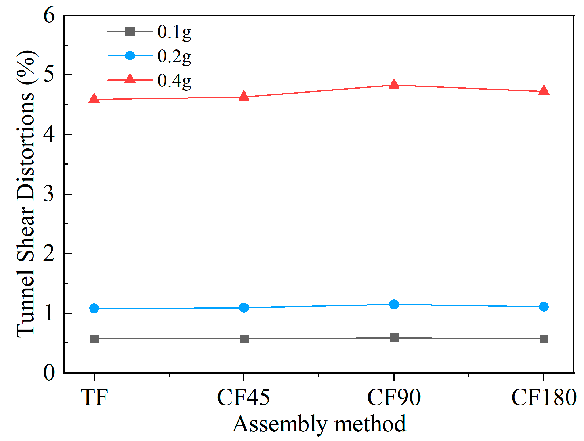
Under the action of 0.1 g, 0.2 g, and 0.4 g earthquakes, the shear deformation of the lining structure with different assembly methods is relatively close, and the difference is only 5.24% under the action of 0.4 g earthquake loading. The overall deformation of the lining structure is not greatly affected by the assembly method, but is mainly controlled by the forced displacement of the formation.
(2)
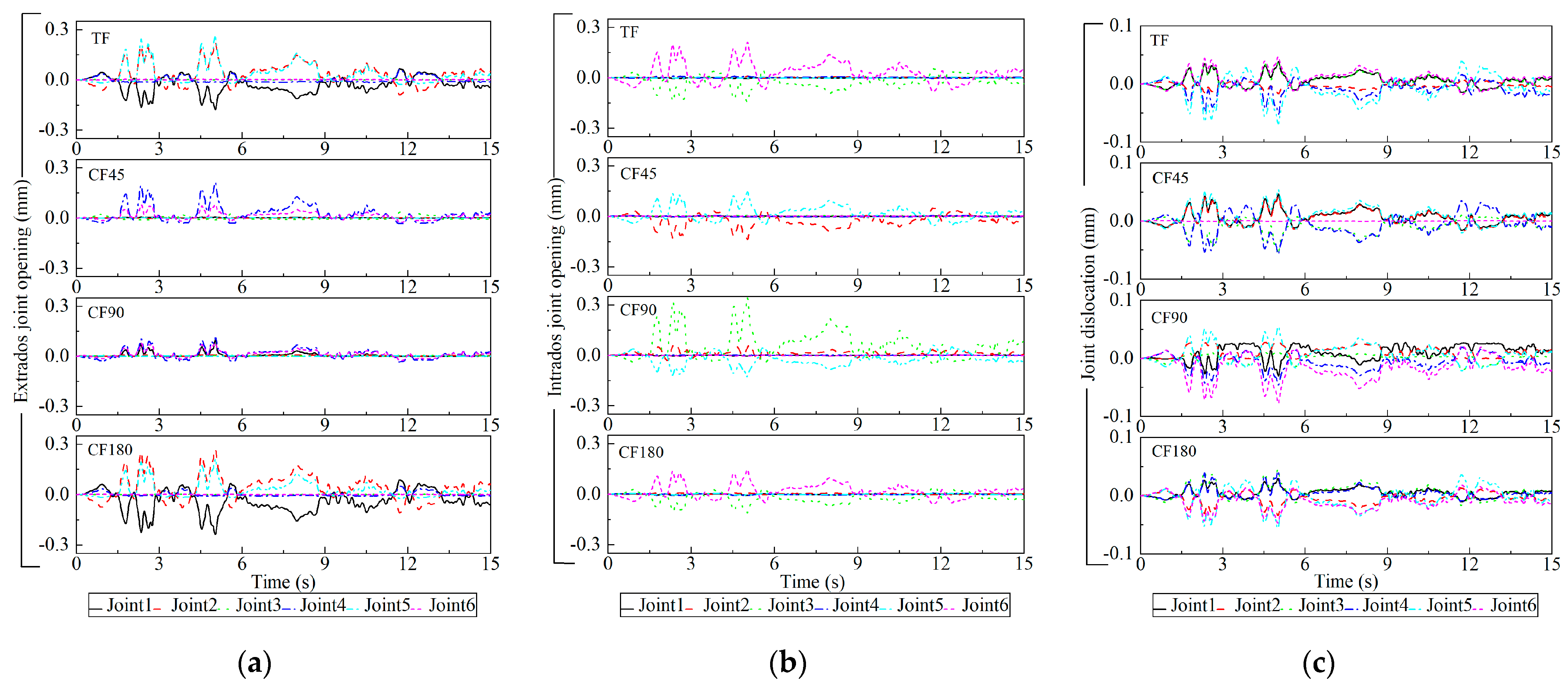
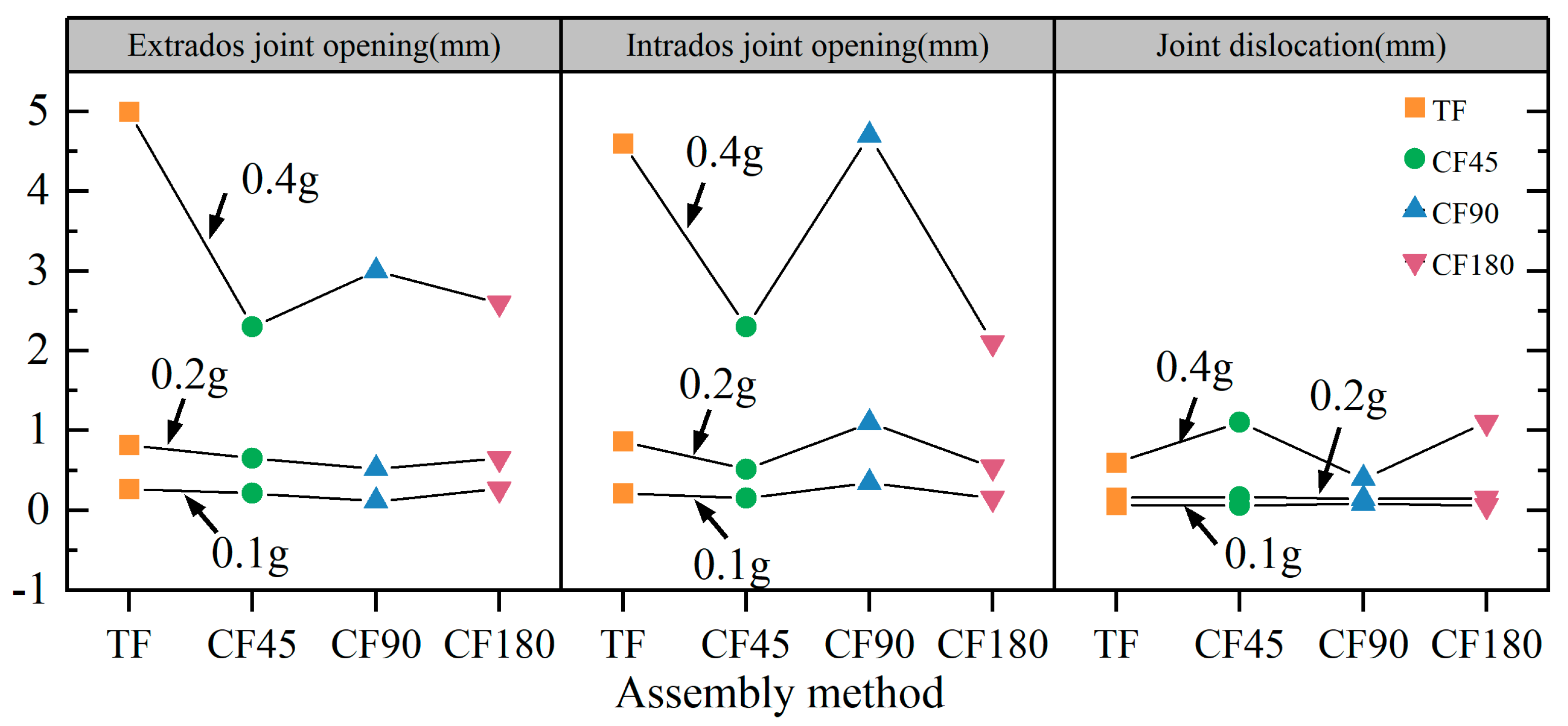
The joint deformation of the segment joints and the internal force distribution of the connecting bolts are heterogeneous, and the location of the maximum joint deformation will change depending on the assembly method. The joint deformation and bolt internal force under the condition of staggered assembly at 90° are more obvious than those of the other three assembly methods, and the internal force distribution of the tunnel structure is less affected by the assembly method. The internal force of the lining is relatively large near the 45° angle with the vault, and the internal force decreases at the joint deformation, which changes the numerical law of the internal force of the tunnel structure.
(3)
During the action of 0.4 g earthquake intensity, the deformation of the joints and the internal force of the bolts of shield tunnels assembled with straight assembly and staggered 90°assembly exceed the limit, while the other two staggered joint assembly methods can maintain safety and waterproof performance. One should avoid placing the capping block on the spandrel for the staggered assembly method from the perspective of earthquake resistance.
(4)
Under the conditions of staggered assembly, the maximum difference in internal force between 1.5 m width and 1.2 m width exceeds 40%, indicating that the internal force characteristics of the structure are significantly affected by changes in the structural stiffness due to changes in segment width.

Author Contributions

S.Z.: methodology, conceptualization, data curation, software, writing; Z.G.: conceptualization, formal analysis, supervision; S.W.: conceptualization, writing, supervision, Funding acquisition; B.C.: conceptualization, investigation, supervision; C.M.: software, visualization. All authors have read and agreed to the published version of the manuscript.

Funding

The work presented in this paper was sponsored by the Supported by Systematic Project of Key Laboratory of New Technology for Construction of Cities in Mountain Area (No. LNTCCMA-20200104), the Systematic Project of Guangxi Key Laboratory of Disaster Prevention and Structural Safety (No. 2019ZDK005), the Ningbo Natural Science Foundation (2019A610394), the Ningbo Public Welfare Science and Technology Planning Project (No. 2019C50012). These financial supports are gratefully acknowledged.

Data Availability Statement

The data used to support the findings of this study are included in the article.

Conflicts of Interest

The authors declare no conflict of interest.

References

  1. Shen, Y.; Zhang, D.; Wang, R.; Li, J.; Huang, Z. Sbd-k-medoids-based long-term settlement analysis of shield tunnel. Transp. Geotech. 2023, 42, 101053. [Google Scholar] [CrossRef]
  2. Xu, L.; Guo, J.; Xu, C.; Chen, R.; Lin, J. Study on Dynamic Response of Soil Layer at the Bottom of Subway Shield Tunnel under Seismic Action. Geotech. Geol. Eng. 2022, 41, 1635–1646. [Google Scholar] [CrossRef]
  3. Masanori, H. Dynamic Behaviors of Underground Structures during Earthquakes and Earthquake-Resistant Design; Springer: Berlin/Heidelberg, Germany, 2014; pp. 229–273. [Google Scholar]
  4. Yang, L.; Xu, C.; Du, X. Causal Analyses of Different Degree of Earthquake Damage Occurred on Daikai Subway Station and Its Running Tunnels during Kobe Earthquake. J. Disaster Prev. Mitig. Eng. 2020, 40, 326–336. [Google Scholar]
  5. Liu, R.; Zhu, Z. Review of Earthquake Damage Prediction for Underground Structures. China Earthq. Eng. J. 2020, 42, 1349–1360. [Google Scholar]
  6. Liu, X.; Bai, Y.; Yuan, Y.; Mang, H.A. Experimental Investigation of the Ultimate Bearing Capacity of Continuously Jointed Segmental Tunnel Linings. Struct. Infrastruct. Eng. 2016, 12, 1364–1379. [Google Scholar] [CrossRef]
  7. Du, X.-L.; Li, Y.; Xu, C.-S.; Lu, D.-C.; Xu, Z.-G.; Jin, L. Review on Damage Causes and Disaster Mechanism of Daikai Subway Station During 1995 Osaka-Kobe Earthquake. Yantu Gongcheng Xuebao/Chin. J. Geotech. Eng. 2018, 40, 223–236. [Google Scholar]
  8. Weng, M.-C.; Wu, J.-H.; Hwang, J.-H.; Chigira, M.; Massey, C. Preface to the Special Issue of Geo-Hazards Induced by the 1999 Chi-Chi Earthquake, Taiwan: Lessons Learned and Progress in Two Decades. Eng. Geol. 2022, 297, 106505. [Google Scholar] [CrossRef]
  9. Huang, Z.K.; Pitilakis, K.; Tsinidis, G.; Argyroudis, S.; Zhang, D.M. Seismic Vulnerability of Circular Tunnels in Soft Soil Deposits: The Case of Shanghai Metropolitan System. Tunn. Undergr. Space Technol. 2020, 98, 103341. [Google Scholar] [CrossRef]
  10. Gong, G.; Liang, J.; Ba, Z.; Xu, A.; Yan, Q.; Wang, Z. Seismic Transverse Time-History Analysis of Shield Tunnel in Complex Soft Soil. Tianjin Daxue Xuebao (Ziran Kexue Yu Gongcheng Jishu Ban)/J. Tianjin Univ. Sci. Technol. 2019, 52, 106–112. [Google Scholar]
  11. Dong, S.H.; Zhang, X.Y.; Jia, C.X.; Li, S.Q.; Wang, K. Study on Seismic Response and Vibration Reduction of Shield Tunnel Lining in Coastal Areas. Sustainability 2023, 15, 4185. [Google Scholar] [CrossRef]
  12. Khan, M.A.; Sadique, M.R.; Harahap, I.H.; Zaid, M.; Alam, M.M. Static and Dynamic Analysis of the Shielded Tunnel in Alluvium Soil with 2d Fem Model. Transp. Infrastruct. Geotechnol. 2022, 9, 73–100. [Google Scholar] [CrossRef]
  13. Arnau, O.; Molins, C. Theoretical and Numerical Analysis of the Three-Dimensional Response of Segmental Tunnel Linings Subjected to Localized Loads. Tunn. Undergr. Space Technol. 2015, 49, 384–399. [Google Scholar] [CrossRef]
  14. Shen, Y.; Zhong, Z.; Li, L.; Du, X.; El Naggar, M.H. Seismic Response of Shield Tunnel Structure Embedded in Soil Deposit with Liquefiable Interlayer. Comput. Geotech. 2022, 152, 105015. [Google Scholar] [CrossRef]
  15. Zhang, W.-J.; Cao, W.-Z. Mechanical and Waterproof Performances of Joints of Shield Tunnels with Large Cross-Section under Earthquakes. Yantu Gongcheng Xuebao/Chin. J. Geotech. Eng. 2021, 43, 653–660. [Google Scholar]
  16. Zhu, T.; Wang, R.; Zhang, J.-M. Seismic Response Analysis of Shield Tunnels in Liquefiable Soils. Yantu Gongcheng Xuebao/Chin. J. Geotech. Eng. 2019, 41, 57–60. [Google Scholar]
  17. Wu, H.; He, C.; Yan, Q.; Feng, K.; Cheng, T. A Study on Curve Fitting Algorithm of Curved Shield Tunnels Assembled by Universal Wedge Segments and Its Application. Tiedao Xuebao/J. China Railw. Soc. 2016, 38, 90–98. [Google Scholar]
  18. Wang, S.; Shen, X.; He, X.; Yao, J. A Model Test for the Mechanical Property and Failure Mode of Lining Segments with Different Assembly Types of Shield Tunnel. China Civ. Eng. J. 2017, 50, 114–124. [Google Scholar]
  19. Blom, C.B.M.; Van Der Horst, E.J.; Jovanovic, P.S. Three-Dimensional Structural Analyses of the Shield-Driven ‘Green Heart’ Tunnel of the High-Speed Line South. Tunn. Undergr. Space Technol. 1999, 14, 217–224. [Google Scholar] [CrossRef]
  20. Li, W.; He, C. Study on Mechanical Behavior and Controlling Assembling Modes of Universal Segment Lining for Shield Tunnel. Tiedao Xuebao/J. China Railw. Soc. 2007, 29, 77–82. [Google Scholar]
  21. Teachavorasinskun, S.; Chub-uppakarn, T. Influence of Segmental Joints on Tunnel Lining. Tunn. Undergr. Space Technol. 2010, 25, 490–494. [Google Scholar] [CrossRef]
  22. Feng, K.; He, C.; Su, Z. Prototype Test on Failure Characteristics of Segmental Lining Structure for Nanjing Yangtze River Tunnel. Xinan Jiaotong Daxue Xuebao/J. Southwest Jiaotong Univ. 2011, 46, 564–571. [Google Scholar]
  23. Wang, R.-L.; Zhang, D.-M. Mechanism of Transverse Deformation and Assessment Index for Shield Tunnels in Soft Clay under Surface Surcharge. Yantu Gongcheng Xuebao/Chin. J. Geotech. Eng. 2013, 35, 1092–1101. [Google Scholar]
  24. Liu, X.; Zhang, Y.; Wang, R. Discussion on Deformation and Failure of Segmental Metro Tunnel Linings. China Civ. Eng. J. 2020, 53, 118–128. [Google Scholar]
  25. Zhao, W.-S.; He, X.-Z.; Chen, W.-Z.; Yang, J.-P.; Wang, H.; Yuan, J.-Q. Method for Analyzing Seismic Response of Shield Tunnel and Its Application. Yantu Lixue/Rock Soil Mech. 2012, 33, 2415–2421. [Google Scholar]
  26. Wang, C.; Tang, P.; Zhuang, H.; Yang, M. Seismic Performance of Large Shield Tunnel under the Yangzi River with Considering the Staggered Joints. J. Nat. Disasters 2021, 30, 116–123. [Google Scholar]
  27. Gou, Y.; Huang, Q.; Wang, L.; Yan, Y.; Jia, S. Study on Structural Behaviors and Adaptability of Shield Tunnel in the Ground Fissure Environment. Railw. Stand. Des. 2020, 64, 117–125. [Google Scholar]
  28. Chen, H.-W. Seismic Response Analysis of Shield Tunnel Considering Joint Effect. Urban Rapid Rail Transit 2018, 31, 78–85. [Google Scholar]
  29. Zhang, W.; Lu, Q.; Zhang, G.; Li, H. Study on Dynamic Response of Shield Tunnel Ring Structure by Cap Location. Chin. J. Undergr. Space Eng. 2020, 16, 588–595+609. [Google Scholar]
  30. Zhuang, H.; Hu, Z.; Wang, X.; Chen, G. Seismic Responses of a Large Underground Structure in Liquefied Soils by Fem Numerical Modelling. Bull. Earthq. Eng. 2015, 13, 3645–3668. [Google Scholar] [CrossRef]
  31. Sharari, N.; Fatahi, B.; Hokmabadi, A.S.; Xu, R. Impacts of Pile Foundation Arrangement on Seismic Response of Lng Tanks Considering Soil–Foundation–Structure Interaction. J. Perform. Constr. Facil. 2022, 36, 04021110. [Google Scholar] [CrossRef]
  32. Tao, L.; Ding, P.; Lin, H.; Wang, H.; Kou, W.; Shi, C.; Li, S.; Wu, S. Three-Dimensional Seismic Performance Analysis of Large and Complex Underground Pipe Trench Structure. Soil Dyn. Earthq. Eng. 2021, 150, 106904. [Google Scholar] [CrossRef]
  33. Zhuang, H.-Y.; Ren, J.-W.; Wang, R.; Miao, Y.; Chen, G.-X. Elasto-Plastic Working States and Seismic Performance Levels of Frame-Type Subway Underground Station with Two Layers and Three Spans. Yantu Gongcheng Xuebao/Chin. J. Geotech. Eng. 2019, 41, 131–138. [Google Scholar]
  34. Pakbaz, M.C.; Yareevand, A. 2-D Analysis of Circular Tunnel against Earthquake Loading. Tunn. Undergr. Space Technol. 2005, 20, 411–417. [Google Scholar] [CrossRef]
Figure 1. Description of soil profile.
Buildings 13 02039 g001
Figure 2. Dynamic calculation model of soil layers and tunnel structure.
Buildings 13 02039 g002
Figure 3. Schematic diagram of the division of the general ring segments.
Buildings 13 02039 g003
Figure 4. Schematic diagram of shield tunnel unit form and connection mode and positive direction of tunnel lining internal force.
Buildings 13 02039 g004
Figure 5. Time history of seismic wave after peak adjustment: (a) 0.1 g, (b) 0.2 g, (c) 0.4 g.
Buildings 13 02039 g005
Figure 6. Maximum shear deformation of shield tunnel under different assembly methods.
Buildings 13 02039 g006
Figure 7. Time histories of segment joint deformation under different assembly methods with the input 0.1 g seismic loading: (a) extrados opening, (b) intrados opening, (c) shear dislocation.
Buildings 13 02039 g007
Figure 8. Maximum deformation of segment joints under different assembly methods.
Buildings 13 02039 g008
Figure 9. Internal force curves of joint bolts under different assembly methods with the input 0.1 g seismic loading: (a) axial force, (b) shear force.
Buildings 13 02039 g009
Figure 10. Maximum internal force of bolts with different assembly methods.
Buildings 13 02039 g010
Figure 11. Envelope diagram of tunnel internal force under different assembly methods with the input 0.1 g seismic loading: (a) radial axial force: FR, (b) circumferential axial force: FN, (c) circumferential bending moment: M.
Buildings 13 02039 g011
Figure 12. Maximum internal force of tunnel under different assembly methods.
Buildings 13 02039 g012
Figure 13. The maximum mechanical results of different assembly methods: (a) TF; (b) CF45; (c) CF90; (d) CF180.
Buildings 13 02039 g013
Figure 14. Schematic diagram of general ring segments with different widths: (a) segment width: 1.2 m; (b) segment width: 1.5 m.
Buildings 13 02039 g014
Figure 15. Maximum deformation time history curves of segment joints under different widths.
Buildings 13 02039 g015
Figure 16. Maximum internal force of joint bolts under different widths.
Buildings 13 02039 g016
Figure 17. Envelope diagram of internal force of segments under different widths: (a) radial axial force: FR, (b) circumferential axial force: FN, (c) circumferential bending moment: M.
Buildings 13 02039 g017
Figure 18. MAPS and MIPS of shield tunnel under different widths: (a) TF1.2; (b) CF1.2; (c) FT1.5; (d) CF1.5.
Buildings 13 02039 g018
Table 1. Material parameters of numerical model.
MaterialsThickness (m)Density (kg/m3)Poisson’s
Ratio
Elastic
Modulus (MPa)
φCohesion
(kPa)
Muddy silty clay0~1817800.357716°20
Silty fine sand18~2120000.2830030°0
Muddy silty clay21~3917800.358416°20
Silty clay39~5018400.3230020°36
Concrete-25000.23.45 × 104--
Bolt-78000.22.10 × 105--
Table 2. Assembly methods of segments.
Assembling MethodSchematic DiagramInstructions
CF45Buildings 13 02039 i001The front and rear proximity rings rotate 45 degrees relative to the middle ring
CF90Buildings 13 02039 i002The front and rear proximity rings rotate 90 degrees relative to the middle ring
CF180Buildings 13 02039 i003The front and rear proximity rings rotate 180 degrees relative to the middle ring
TFBuildings 13 02039 i004Straight assembly
Table 3. MAPS and MIPS of four shield tunnel assembly methods under earthquake action.
Assembly MethodSeismic WaveMAPS (MPa)MIPS (MPa)
TFPGA = 0.1 g2.547.25
CF453.826.89
CF903.987.02
CF1803.947.63
TFPGA = 0.2 g3.988.70
CF456.178.11
CF905.988.25
CF1805.898.70
TFPGA = 0.4 g8.8520.06
CF4519.119.64
CF9019.619.64
CF18019.220.01
Table 4. Seismic performance evaluation of shield tunnel under different assembly methods.
Research
Object
Mechanical
Property
Joint
Deformation
Bolt
Internal Force
Stress
Property
Seismic Performance Evaluation
Assembly
method
Radial force/
Circumferential force/
Bending moment
Extrados opening/
Intrados opening/
Dislocation
Axial force/
Shear force
MAPS/
MIPS
TF
CF45
CF90
CF180
706 kN (CF90)/556 kN (CF45)/190 kN·m (CF45)5 mm (TF)/
4.7 mm (CF90)/
1.1 mm (CF180)
490 kN (TF)/
239 kN(CF180)
19.6 MPa
(CF90)/
20.6 MPa
(TF)
The methods TF and CF90 do not meet the seismic design requirements
Table 5. Seismic performance evaluation of shield tunnels under different segment widths.
Research
Object
Mechanical
Property
Joint
Deformation
Bolt
Internal Force
Stress
Property
Seismic Performance Evaluation
Segment
Width
Radial force/
Circumferential force/
Bending moment
Extrados opening/
Intrados opening/
Dislocation
Axial force/
Shear force
MAPS/
MIPS
TF1.2
CF1.2
TF1.5
CF1.5
905 kN (TF1.5)/
582 kN (CF1.5)/
280 N·m (CF1.5)
5 mm (TF1.2)/
4.6 mm (TF1.2)/
1.1 mm (CF1.2)
490 kN (TF1.2)/
239 kN (CF1.2)
16.7 MPa
(CF1.2)/
19.5 MPa
(TF1.2)
Shielded tunnel with a 1.5 m width segment is better than the 1.2 m wide shielded tunnel in terms of seismic performance
Disclaimer/Publisher’s Note: The statements, opinions and data contained in all publications are solely those of the individual author(s) and contributor(s) and not of MDPI and/or the editor(s). MDPI and/or the editor(s) disclaim responsibility for any injury to people or property resulting from any ideas, methods, instructions or products referred to in the content.

