Article

Experimental Investigation of the CFS-PU Composite Wall Panel under Axial Compression

1
Department of Structural Engineering and Technical Mechanics, Faculty of Civil Engineering, University of Rijeka, Radmile Matejčić 3, 51000 Rijeka, Croatia
2
Palijan d.o.o., 10000 Zagreb, Croatia
*
Author to whom correspondence should be addressed.
Buildings 2023, 13(8), 1897; https://doi.org/10.3390/buildings13081897
Submission received: 30 June 2023 / Revised: 21 July 2023 / Accepted: 24 July 2023 / Published: 26 July 2023
(This article belongs to the Special Issue Cold-Formed Steel Structures)

Abstract

:
This study presents an innovative design for a cold-formed steel polyurethane (CFS-PU) composite wall panel, combining a cold-formed steel frame, a polyurethane foam infill, and a gypsum fibreboard sheathing. The foam filling process, in which the foam is injected under pressure, ensures uniform distribution, bonding, and interaction of all panel components. The aim of the study is to evaluate the behaviour of the CFS-PU composite panels and the influence of the PU foam and sheathing on the performance of the CFS frame structure. For this purpose, a comprehensive test programme was conducted with nine full-scale specimens, including four CFS-F specimens without infill and sheathing and five CFS-PU specimens with infill and sheathing on both sides. The study examined various aspects of the specimens, including failure modes, stability, stiffness, load-bearing capacity, and ductility index. By analysing these parameters, valuable insights were gained into the performance characteristics of the composite wall panels. The load-bearing capacity of the CFS-PU test specimens was improved by 2.34 times and the stiffness by 1.47 times compared to the CFS-F test specimens. The positive results highlight the potential of foam and sheathing in improving the axial compression performance of CFS walls.

1. Introduction

Cold-formed steel (CFS) structures are widely used for residential buildings worldwide due to their environmental friendliness, lightweight nature, ease of installation, and convenience of transportation. Additionally, CFS sections are commonly used in building construction for various applications such as roofing, flooring, walls, window reinforcements, and mezzanine flooring [1]. CFS frame walls are a popular alternative to traditional timber frame construction and concrete masonry in both residential and commercial construction. They are particularly well suited for low-rise buildings such as townhouses, flat buildings, and offices. In addition, CFS framed walls are a good option for walls in prefabricated frame structures, which are becoming increasingly important as construction becomes more industrialized. In recent years, composite walls of CFS structures filled with lightweight materials have emerged as a new development in the construction industry. These lightweight fillers are often made from industrial waste [2,3,4], making them an attractive option for low-carbon buildings. As a result, interest in investigating and developing CFS composite walls filled with lightweight materials has grown. Numerous studies have examined the structural performance of these walls [5,6,7], with favourable findings. Incorporating various load-bearing materials into the infill of the wall frame can provide additional stiffening and prevent local buckling of the CFS frame while improving the wall’s axial compression capacity, seismic performance, and ductility. Hegyi and Dunai [8,9] successfully used polystyrene aggregate concrete as a bracing material to restrain the global and distorting buckling modes of CFS elements. Similarly, Wu and Chao [10,11] presented a frame wall filled with lightweight flue gas desulphurization gypsum and polystyrene granules, which improved the shear and axial load capacity as well as compressive stiffness compared to an unfilled wall. In addition, Heyden and Lange [12] found that filling a CFS C-section with foam resulted in a higher ultimate strength of the member, while Sagadevan and Rao [13] showed that the use of polyurethane foam as a filling material increased the flexural, shear, and axial compressive strengths as well as the load-bearing capacities of beams, columns, and purlins. Studies on the structural performance of CFS composite walls filled with lightweight fill materials have yielded positive results indicating significant potential to improve the overall structural performance of buildings, making them an attractive option for improved structures with increased resistance and durability.
In addition to filling CFS composite walls with lightweight materials to improve their structural performance, another approach can be to stiffen the walls with sheathings. Several studies have investigated the influence of sheathing on the load-bearing capacity of CFS composite walls, with promising results. Miller and Pekoz [14,15] have conducted experiments on gypsum-sheathed walls and proposed effective length coefficients to calculate the axial compression bearing capacity. Tian and Wang [16,17,18] found that adding sheathing on both sides of the studs and decreasing the screw spacing resulted in increasing the load capacity of the wall. Vieira and Schafer [19,20,21] tested different sheathing configurations, boundary conditions, and lengths of test specimens and found that they significantly affected the strength and stability of the studs. They also found that the sheathing can constrain deformation and global buckling, resulting in local buckling being the primary limit state for all practical lengths. There are numerous other theoretical and experimental studies in the literature [22,23,24,25,26,27] that have investigated the effects of various factors on the ability of such wall systems to withstand axial loads, such as the spacing between screws, the shape and spacing of studs, the type of sheathing, the presence of holes or notches in the studs, and the height of the wall studs.
CFS frame walls are a crucial element in CFS structures and serve as primary load-bearing components. They are responsible for both lateral and vertical resistance, which is crucial for the overall load bearing, stability, and serviceability of the structure. Therefore, it is crucial to evaluate the axial compression behaviour of CFS frame walls. This paper presents an innovative design for a CFS-PU composite wall panel made of a CFS frame structure that incorporates infilled polyurethane (PU) foam and gypsum sheathing on both sides. The inventiveness of the CFS-PU composite wall panel lies in its PU foam-filling process and in the application of a novel angle bracket connection for anchoring the CFS frame structure. In this method, the PU foam is injected under pressure in controlled factory conditions as opposed to conventional methods that require on-site filling. This results in an even distribution of the PU foam inside the panel, which enables the connection and interaction of all panel components. Ultimately, this interaction is expected to improve the stability of the CFS frame structure. In addition, this method allows the wall panels to be manufactured under fully controlled conditions, which improves their acoustic and thermal resistance. As no filling work is required on site, the panels can be manufactured with precision and consistency, resulting in a high-quality product. Such composite wall panels are an innovation for the construction of industrially produced buildings with almost zero energy.
This paper investigates the performance of CFS-PU composite wall panels compared to CFS frame structures without infill and sheathing to gain insight into the behaviour and performance of CFS-PU composite walls. To achieve this goal, an experimental study was conducted with nine test specimens subjected to axial compressive loading. Four of these test specimens were CFS frames, while the remaining five consisted of CFS-PU composite wall panels. The study compared and analysed the test results of the CFS frames and CFS-PU test specimens to evaluate the effectiveness of CFS-PU composite walls. In particular, the analysis focused on evaluating the influence of PU foam and sheathing on various aspects, including the stability of the CFS structure, failure modes, load-bearing capacity, and ductility. It is expected that this study will provide valuable insights into the design and optimisation of CFS composite structures for various applications in the construction industry. Overall, the composite wall panel presented offers benefits such as improved construction efficiency and reduced structural requirements. In addition, polymer foam in composite panels has two functions, one is an insulating effect, and the other is an influence on increasing the load-bearing capacity of the panels. This dual functionality highlights the product’s potential for improved energy efficiency and structural performance, which has important implications for the development of cost-effective and sustainable building systems that meet the demands of modern construction. By better understanding the behaviour of CFS-PU composite walls, designers and engineers can develop more efficient and reliable building systems to meet the growing demand for sustainable and high-performance structures.

2. Experimental Program

2.1. Specimen Description

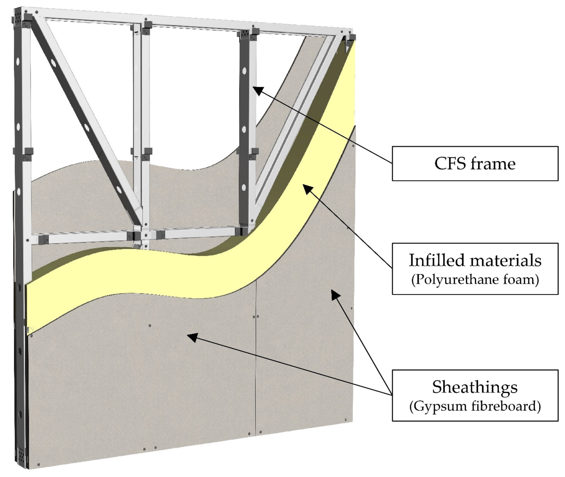
The prototype of the CFS-PU composite wall panel consists of three main components: a CFS frame, gypsum sheathings, and filled polyurethane (PU) foam, as shown in Figure 1.
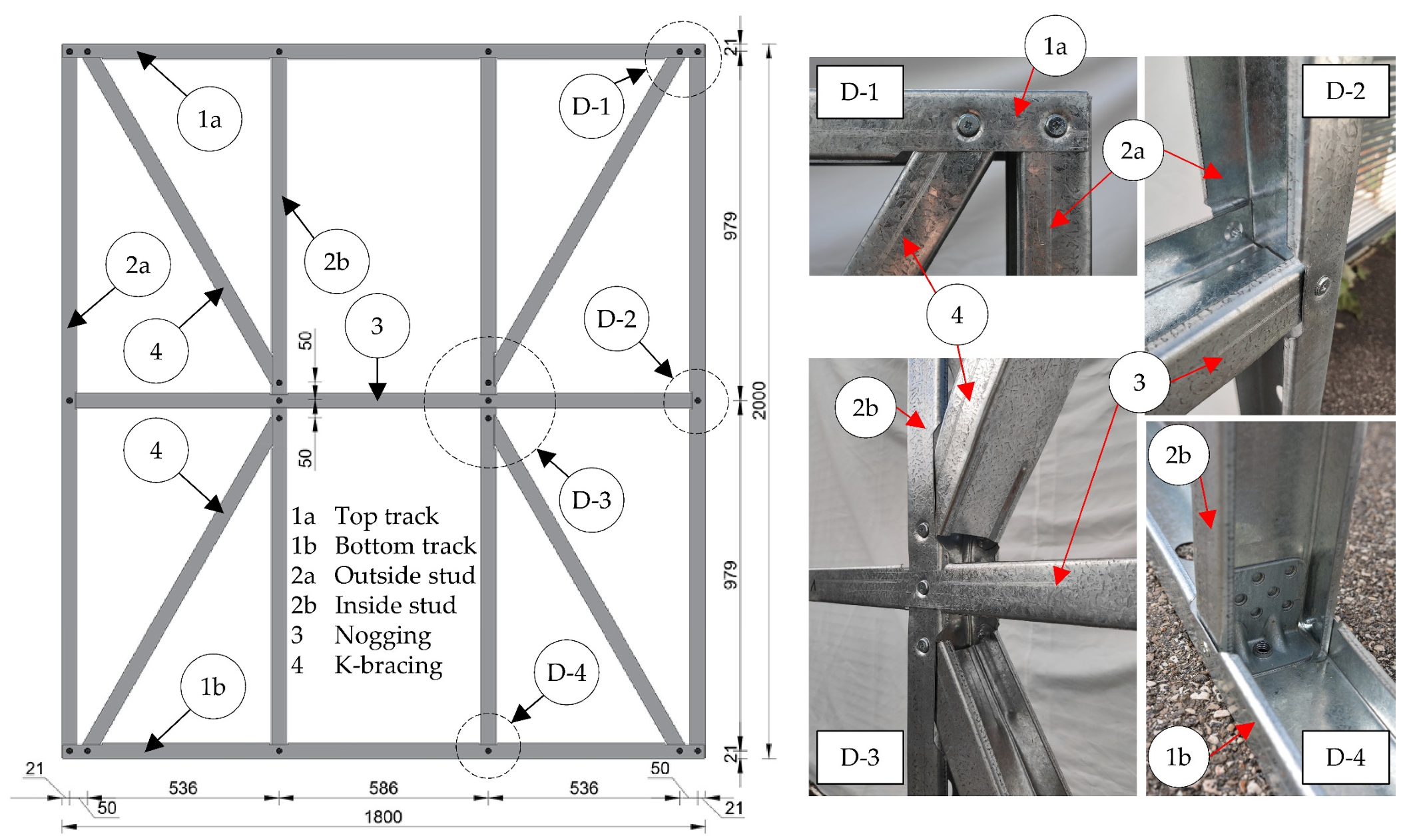
The CFS frame consists of four studs, each 1998 mm long, evenly spaced with an axial distance of 586 mm. These studs are attached to the upper and lower tracks. In addition, the studs are connected in the middle by a nogging with a web notch that allows the passage of the interior studs. The total width and height of the assembled frame are 1800 mm and 2000 mm, respectively. The stability of the frame is achieved by four diagonal braces that form two K-bracing in the outer stud placements. All parts of the CFS frame, including studs, tracks, noggins, and diagonal braces, were manufactured using automated CNC technology of roll forming C-sections with cross-sectional dimensions of 89 mm web × 42 mm flange × 12 mm lip × 1.15 mm thickness in steel grade S550 GD.
The frame parts are connected to each other via the flange dimple of the C-profile with self-drilling screws M6 × 10 class 10.9. Lip notches have been made at the crossing points where the parts are joined together to facilitate the connection and avoid overlapping. Structural details in joints of the CFS frame, such as lip cuts, chamfer cuts, flange punches, web notches, dimples, swages, and service holes were produced using the mentioned technology. The geometry of the CFS frame with the associated details of joints is shown in Figure 2.
Angle brackets are attached to the ends of the studs on both sides and connected to the web of the C-profile by a pressing process in which the material of the bracket is deformed to make a rigid connection. The brackets themselves are manufactured by cold forming and are made of DX51D-Z275 steel with a thickness of 3 mm. A detailed description of the angle bracket and the connection procedure can be found in the article [27]. Nevertheless, it should be noted that the angle brackets used in this study differ from those listed in the article [27]. The difference is that the angle brackets in this article have additional M12 threaded holes, whereas the brackets in the mentioned article do not. This allows the wall panel to be anchored and connected to other structural elements without the need for the nut and without having to access the inside of the wall panel.
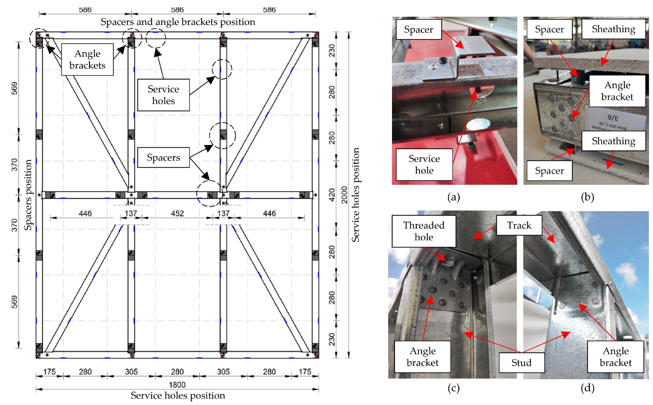
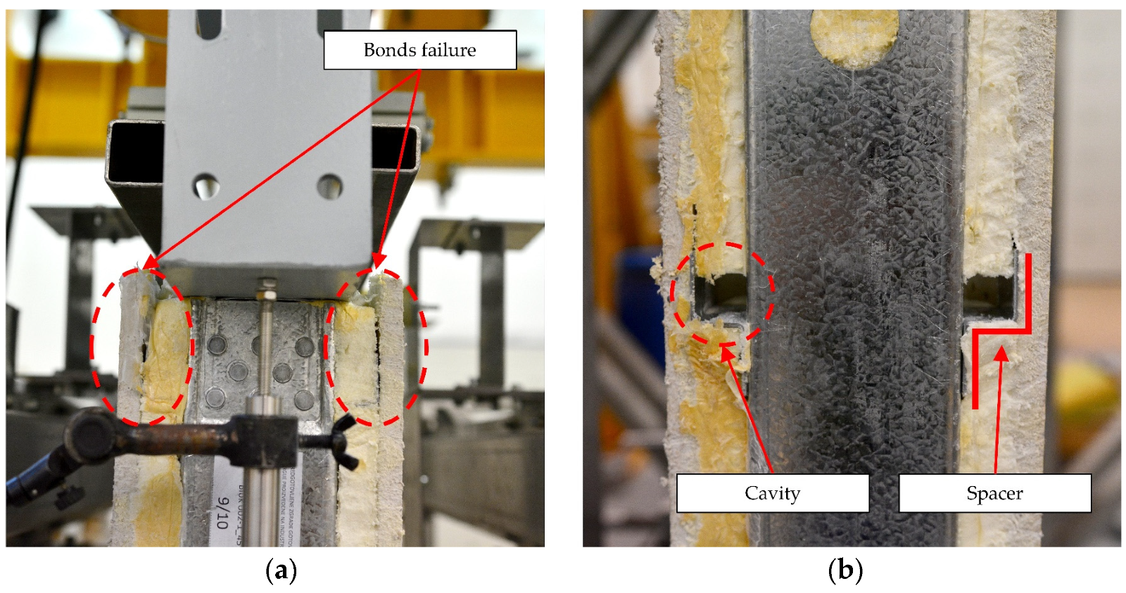
To ensure the intended distance between the sheathings and the CFS frame, spacers were used and placed on both sides of the frame. The spacers are made of cold-formed steel, S550 GD, Z-shaped, 60 mm long × 40 mm wide × 23 mm high, and 1.5 mm thick. They are fixed to the flanges of the CFS frame elements with an aluminium rivet and a 3.5 × 50 mm self-tapping countersunk screw. The spacers have another important function: they create space between the sheathing and the CFS frame, which is later filled with PU foam. This design helps to improve the thermal properties of the composite wall panel and reduce thermal bridges. In addition, the spacers ensure that the PU foam can be distributed evenly over all parts of the wall panel during the filling process.
To further improve the even distribution of the PU foam, service holes with a diameter of 34 mm were cut on the web of the C-profile in the frame parts. These holes, together with the position of the angle brackets and spacers, can be seen in Figure 3.
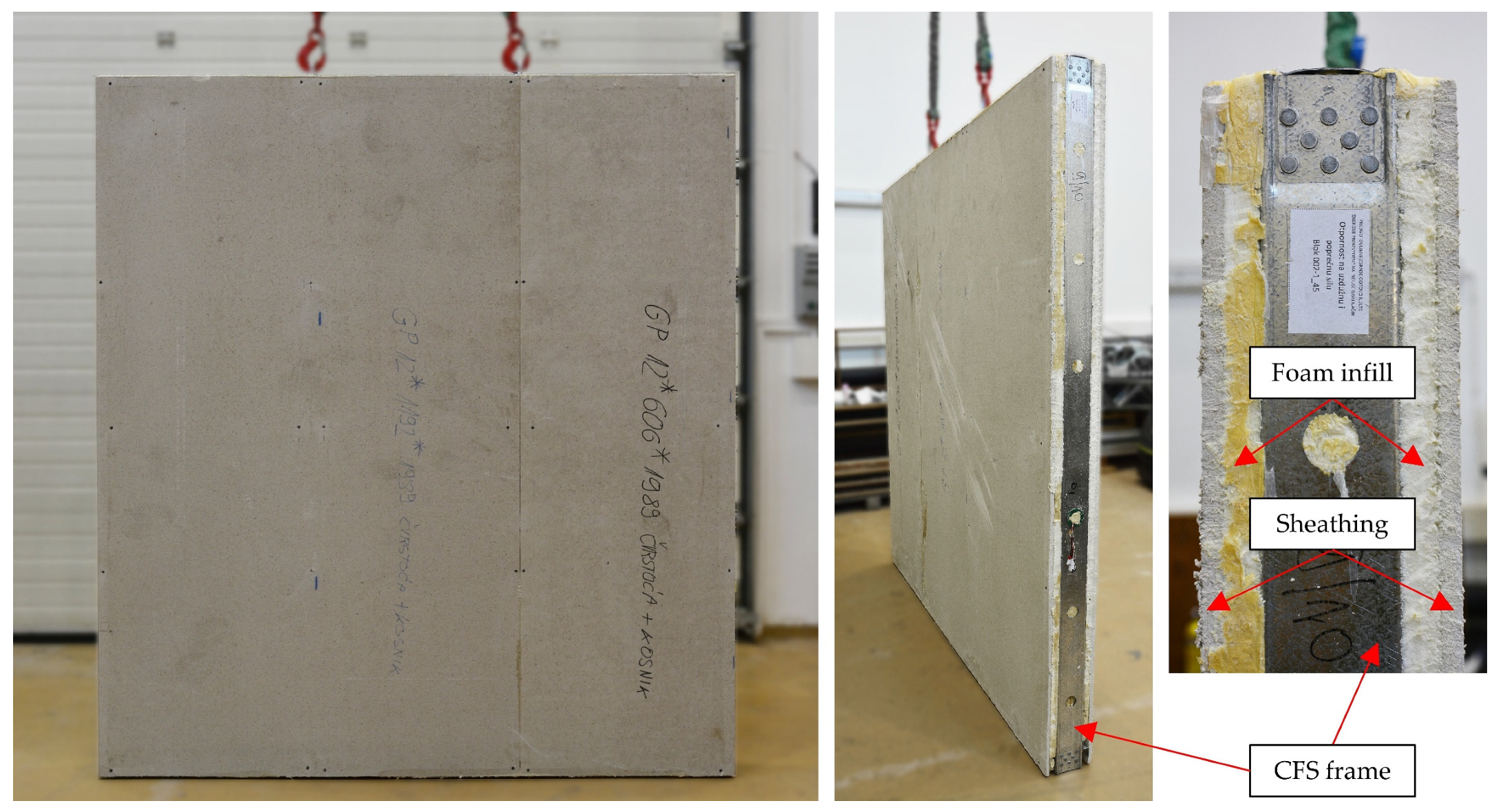
To ensure a solid surface of the wall panels, sheathing is used on both sides of the frame, consisting of gypsum fibreboards with a thickness of 12.5 mm. Each sheathing consists of two boards placed next to each other with the dimensions 1195 × 1990 and 595 × 1990 mm. The sheathings are intentionally made smaller than the CFS frame so that there is a 5 mm free margin on each side to prevent vertical load transfer to the sheaths and to ensure load transfer to the CFS frame only. The sheathings are fastened to the CFS frame with 3.5 × 50 mm self-tapping countersunk drywall screws at the edges of the boards and at the position of the studs and nogging. The screws are placed at a mutual vertical distance of 485 mm so that the screws cannot collide with the spacers. Each board is individually fastened to the CFS frame.
A CFS-PU composite wall panel is filled with closed-cell PU foam with a nominal density of 45 kg/m3, which is injected under pressure between the sheathings and the CFS frame. The PU foam fills the space between the CFS elements of the frame and in the process of expansion achieves an adhesive bond with the CFS structure and sheathings. The results of the adhesive bond test can be found in [28,29]. Figure 4 shows the CFS-PU composite wall panel with sheathing and PU foam filling.
The laboratory testing procedure included two groups of specimens: CFS-PU composite wall panels and CFS frame structures without sheathings and PU foam. The specimens are labelled CFS-F/PU-X, where “CFS” stands for cold-formed steel, “F” for frame, “PU” for polyurethane, and “X” is the specimen number. Detailed information on the geometric dimensions of the specimens before the test, including width (w), height (h), thickness (t), and weight, can be found in Table 1. The indices next to the marking stand for the measuring position, where “T” stands for the top edge of the specimen, “B” for the bottom edge of the specimen, “L” for the left edge of the specimen, and “R” for the right edge of the specimen. The measured dimensions in the table were used together with the known densities of the CFS and sheathing panels to determine the average density of the PU foam filling in the specimens.

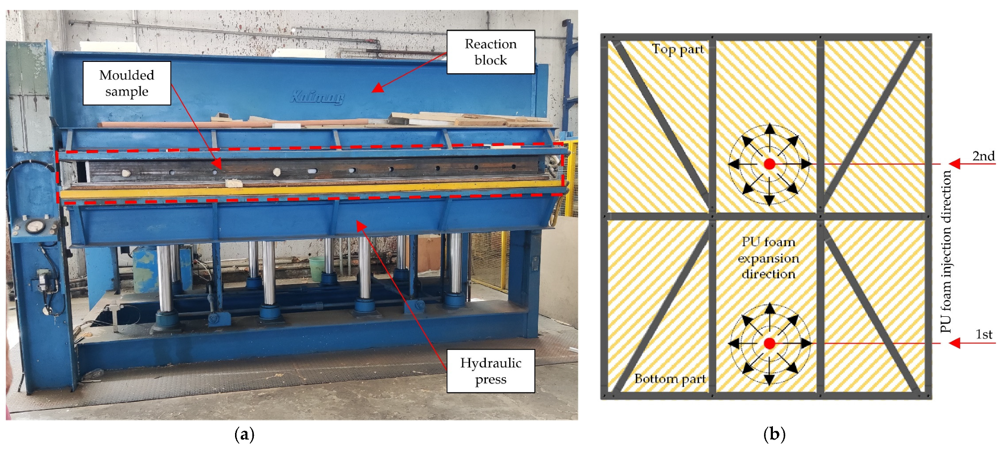
2.2. PU Foam Injection

Prior to the injection procedure, the test specimens, which consisted of a CFS frame and sheathing with pre-installed spacers and angle brackets, were properly assembled. After assembly, the test specimen was placed in a mould to prevent PU foam leakage from the edge areas during the injection process. The specimen was then placed under a press to prevent damage or breakage during the PU foam expansion process and to keep the sheathing stable and secure, as displayed in Figure 5a. A low-pressure polyurethane foam machine with a variable pressure capacity of 4 to 10 bar and an output range of 1000 g/s was used for the foam injection. The PU foam injection process was carried out in two phases, with the PU foam being injected in a liquid state alternately from two positions. During injection, the PU foam was injected into the central stud placement between the interior studs, as shown in Figure 5b. This ensured that the PU foam was evenly distributed over the top and bottom part of the panel. After injection, the panel was left in the press for one hour to allow the PU foam to cure. Once the PU foam had cured, the specimen was removed from the press and demoulded.

2.3. Material Properties

The C-profiles are made of steel grade S550 GD, while the angle brackets are made of steel DX51D-Z275. To determine the mechanical properties of these steels, uniaxial tensile tests were carried out using the Zwick/Roell Z600 universal tensile-compression testing machine. The tests were performed at room temperature according to method A of the Standard EN ISO 6892-1:2019 for metallic materials [30]. The results of these tests, including the average values of the modulus of elasticity  E , the upper yield stresses  R e H , and the tensile strengths  R m  for each steel, can be found in the article [31]. In addition, Table 2 provides a summary of these average values as well as the strains measured with an external extensometer at a gauge length of 50 mm, including the average values of strain at yield  A e , and total percentage strain at maximum force  A g t  and at break  A t . Finally, 
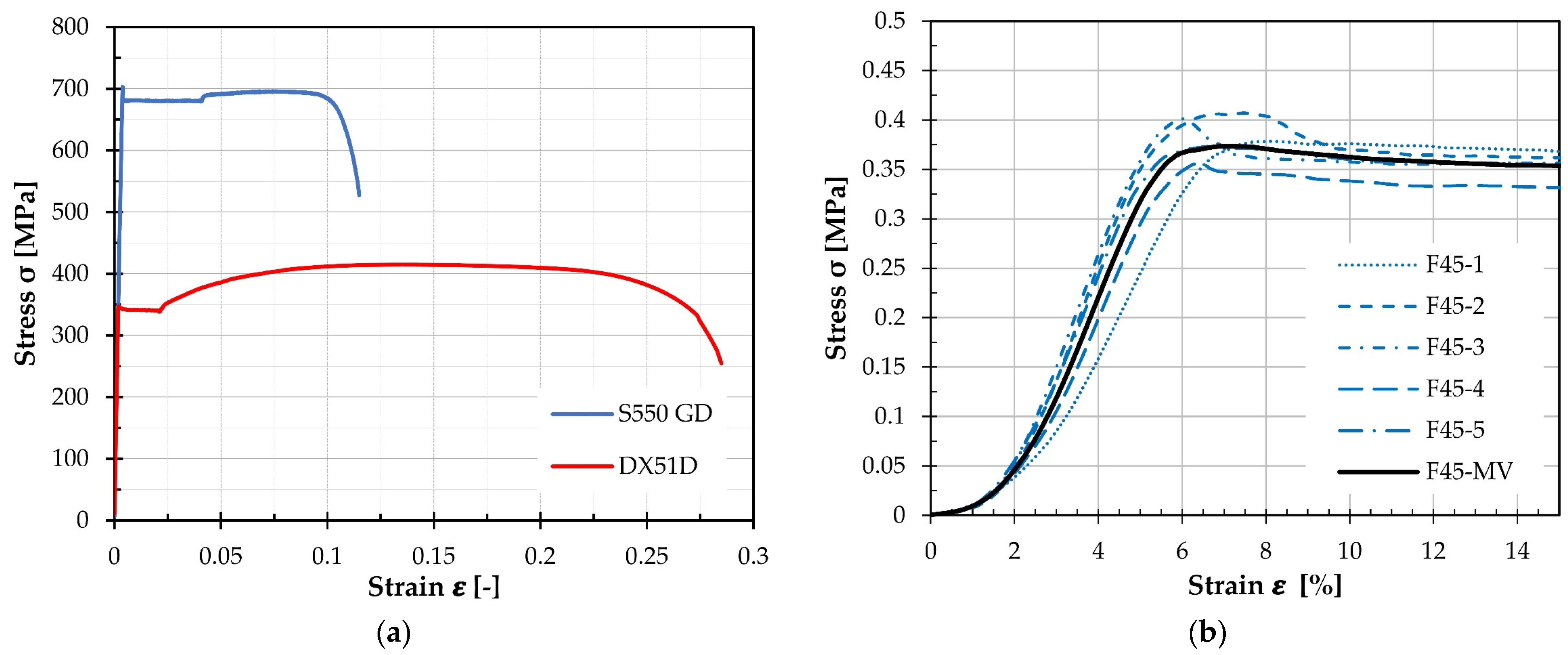
Figure 6a shows the stress–strain curves of the tested materials based on their average values.
To determine the mechanical properties of a PU foam, a compression test was performed using the Zwick/Roell Z600 universal tensile-compression testing machine according to procedure A of the ISO 844:2014 standard [32]. The load was applied by controlling the displacement of the moving crosshead at an appropriate displacement rate of 5 mm/min. The PU foam specimens were taken from the middle part of a preliminary panel specimen, which was not used for the test, but to determine the density of the PU foam. The foam specimens were taken to match the direction of load application on the real panels during the compression test. Standard prisms of size 100 mm × 100 mm × 50 mm were prepared and a total of five specimens were tested.
Prior to the uniaxial compression test, detailed measurements of the dimensions and weights of all specimens were taken and the initial cross-sectional area  A 0 , thickness  h 0 , and density  ρ  of each specimen were calculated. The values of compressive strength  σ m , relative deformation  ε m , and compressive modulus of elasticity  E  are given in Table 3. The stress–strain curves for S550 GD and DX51D-Z275 steel are shown in Figure 6a, while Figure 6b contains the stress–strain curves for PU foam specimens.
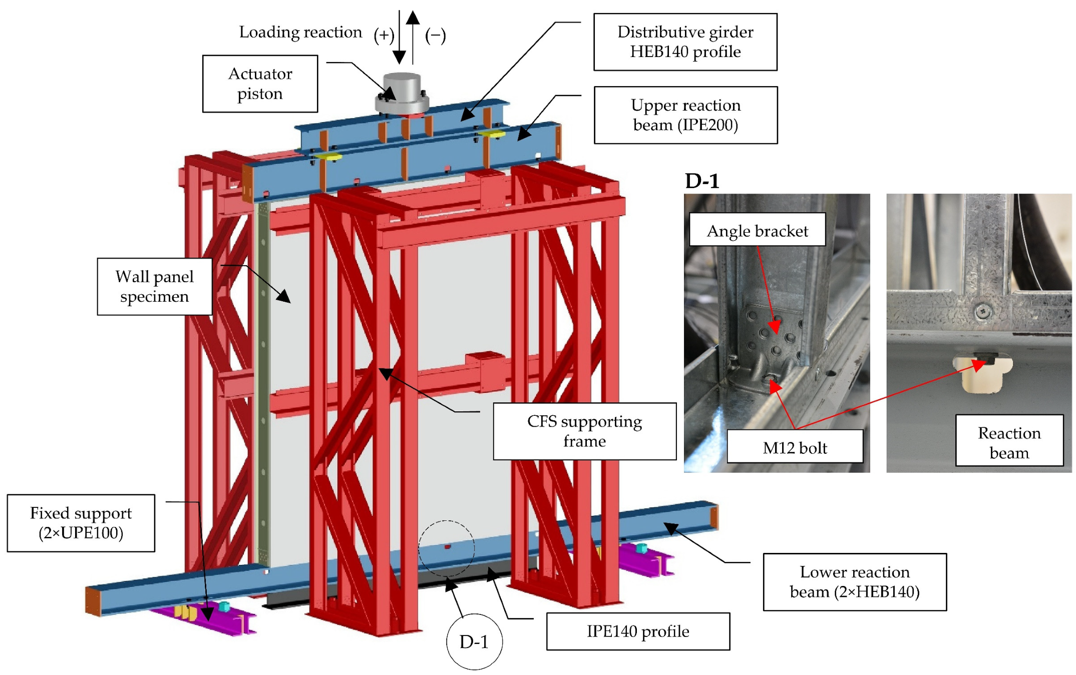
2.4. Test Setup

The test setup is shown in Figure 7. It was designed in such a way that the supports and load conditions correspond to the real-life conditions of the wall panel. This was achieved by connecting the frame tracks to both the lower and upper reaction beams with bolts. The lower reaction beam consists of two HEB140 profiles connected together with four M12 bolts through holes in the end plates of the profiles. Two fixed supports made of symmetrically welded UPE100 profiles served to anchor the lower reaction beam to the rigid concrete base with M36 anchor bolts. The connection between the reaction beam and the fixed supports was made with four M12 bolts on each support. To reduce the deflection of the lower reaction beam during the test, an IPE100 profile was placed centrally under the beam. An IPE200 profile was also used to construct the upper reaction beam. To distribute the load evenly across the upper beam, a smaller HEB140 distribution girder was placed on top and connected to the upper beam with four M12 bolts. To ensure that the tested specimen remained securely attached to the apparatus, the specimen was attached to the lower and upper reaction beams using bolts. Four M12 bolts were used per beam to properly secure the specimen. Before attaching the bolts, holes were cut in the webs and flanges of the two reaction beams. This allowed the bolts to be screwed into the angle brackets that had previously been inserted into the CFS frame. The vertical load was applied using a Zwick/Roell actuator with a capacity of 500 kN. The load was applied by displacement control with a test speed of 2.5 mm/min. To ensure the specimen’s out-of-plane stability, a special CFS frame structure was designed and built. This frame structure was anchored in the concrete base and placed on both sides of the specimen. This structure additionally protected the measuring equipment from damage in case of specimen failure.

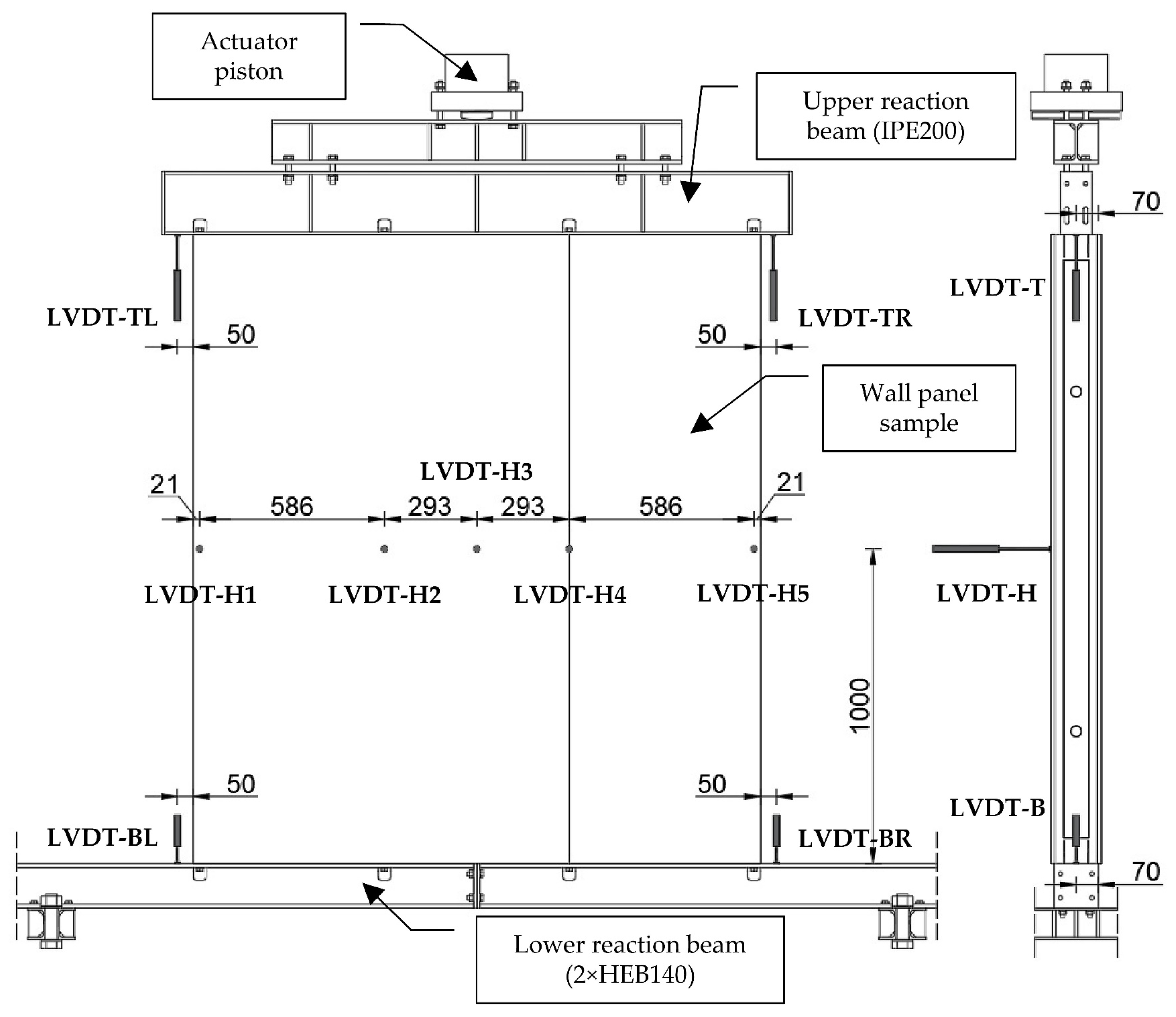
2.5. Instrumentation

During the tests, a total of nine linear variable displacement transformers (LVDTs) were used to measure the displacements. Figure 8 shows the positions of the LVDTs. LVDT-BL and LVDT-BR (both Omega LD320-5) were installed to measure the vertical displacement of the bottom reaction beam, while LVDT-TL and LVDT-TR (both Omega LD320-25) were used to measure the vertical displacement of the upper reaction beam. The remaining five LVDTs, LVDT-H1 to LVDT-H5, (all Omega LD320-50) were used to measure the out-of-plane deflection in the centre of the specimen.
The test management was performed with the Cubus software, while all measurement results of the LVDTs and the force sensor were recorded by the data acquisition system with the SignalExpress 2015 software.

3. Test Results and Failure Modes

3.1. Failure Modes

3.1.1. CFS Frame

During the loading, before the axial loads reached about 70% of the peak loads, no significant buckling was visually observed, apart from the increase in displacement values recorded by the data acquisition system. However, when this threshold was reached, a phenomenon of local buckling was observed at the webs of the wall studs, as shown in Figure 9a. Despite the local buckling, the studs still had a stable strength reserve that allowed them to support the subsequent compressive loads. In addition to local buckling, deformation of the stud flanges was observed, which took the form of distortional buckling. This deformation was mainly observed at the central longitudinal positions of the studs where the lip cuts were made for the connection with the diagonals, as shown in Figure 9b. The two inner studs showed deformations of approximately the same rate, while the flanges of the edge studs showed significantly lower deformations. The loss in strength occurred by the buckling of the entire specimen out of the plane, which was caused by torsional buckling of the internal C-profile. After the loss of load bearing capacity, significant deformations were observed at the joints between the nogging and the outer stud, as well as between the joints of the nogging, diagonals, and inner studs. In the middle of the length of the outer stud, where it is connected to the nogging, there was a remarkable deformation of the stud web in the form of local buckling. The flanges of the stud were also dented where the lip was cut off, while the flanges of the noggin were bent, as shown in Figure 9c. In addition, a combination of torsional–distortional buckling was observed at the junctions of the inner studs with the diagonals and the noggins, as shown in Figure 10. Nevertheless, no significant deformations were detected at the joints of tracks with the studs and the diagonals throughout the test period.

3.1.2. CFS-PU Composite Wall Panel

Similar to the CFS frame specimens, no significant local buckling was visually observed in the CFS-PU composite wall specimens during the loading. However, due to the infill and sheathings, it was not possible to observe the behaviour of the CFS frame within the wall panel during the test. At an average load value of 307.6 kN, an asymmetric increase in displacement was observed on one side of the test specimen, followed by the occurrence of local web buckling on the outer stud in the middle span. Following this observation, the force value dropped by an average of 6.57%. Despite the drop in force, the specimen did not lose its full load capacity and with a further increase in load, an increase in the load capacity was observed. However, there was another sudden drop in force followed by increasing deformation of the buckled web. The test was stopped when the force dropped by 35%. Similar failure modes occurred in all CFS-PU specimens, although the outer studs varied. The position of the failure was always on the middle length of the stud. Figure 11 shows the failure modes of all of the CFS-PU specimens.
After the test was completed, a visual inspection of the outer parts of the specimens was carried out. It was found that the CFS frame at the connection to the lower reaction beam remained relatively unaffected and there was no significant deformation, crushing, or detachment of the foam or sheathing. On the other hand, more significant deformation was observed at the junction of the upper CFS frame with the upper reaction beam, particularly above the outer stud where web buckling occurred. As a result of the buckling of the web and the vertical displacement of the stud, the shear bond between the foam and the sheathing was compromised, resulting in a noticeable failure of the bond between these materials. The failure is shown in Figure 12a. On the other side of the specimen, at the junction between the outer stud and the top beam, no separation or significant deformation was observed. During the unloading stage of the specimen, it was observed that the foam had become detached where spacers had been placed, resulting in the formation of a cavity (Figure 12b). This was observed only on the side where the local web buckling on the outer stud occurred. The foam deformed plastically when subjected to a compressive force, resulting in the formation of a cavity in the contact with spacers once the load was released. It is noteworthy that the cavity was located locally above the spacers and did not extend into the interior of the specimen.
To better understand the area of web buckling failure, the sheathing and foam were partially removed from the CFS-PU-5 specimen, as shown in Figure 13a. As can be seen in Figure 13b, the failure occurred where the cross-section of the C-profile was reduced due to lip cuts for the connection to the nogging. Both flanges buckled and crushed, causing the stud to collapse and the web to deform more. However, no significant deformations were observed on the flanges and the web of the nogging at this point.
Moreover, it was found that another mode of failure had occurred, as shown in Figure 13c. The failure occurred in the connection zone between the diagonal element and the inner stud. Specifically, deformation buckling of the stud flanges was observed to occur at the point where the lip cuts were made to connect the diagonal to the stud. Assuming that the specimens from CFS-PU behave similarly to the specimens from CFS-F, it can be considered that the buckling of the flanges occurred before the web buckled on the outer stud.

3.2. Load–Displacement Responses

The vertical displacement of the specimen  A  was calculated as the difference between the measured vertical displacements of the upper reaction beam and lower reaction beam, as shown in Equation (1).
A = 3 + 4 2 1 + 2 2
The vertical displacements  1  to  4  were measured by LVDT-TL, LVDT-TR, LVDT-BL, and LVDT-BR, respectively. The force P–displacement  A  curves for the CFS frame specimens are shown in Figure 14a, while those for the CFS-PU specimens are shown in Figure 14b.
The force–displacement curves of the CFS-F and CFS-PU specimens show a significant difference. If the curves in the elastic region are observed, it can be seen that the CFS-PU specimens have a greater ability to deform elastically before reaching the yield point. CFS-F specimens begin to yield at an average force of 123.75 kN, while CFS-PU begin to yield at an average force of 271.83 kN. After reaching the peak load point, there is a sudden drop in force and loss of load bearing capacity in the CFS-F specimens. On the other hand, for the CFS-PU specimens, the load capacity decreases slightly but the load continues to increase after a certain displacement. It is important to note that for the CFS-PU-1 and 3 specimens, the ultimate load reached a slightly higher value than the first, while it was lower for the CFS-PU-2 and 5 specimens. The analysis determined that the first force drop for the CFS-PU specimens corresponded to the buckling of the web on the C-profile, while the second force drop was due to the crushing of the C-profile flanges. For the CFS-PU-4 specimen, the buckling of the web and the crushing of the flanges occurred simultaneously, resulting in only one visible peak. Furthermore, in contrast to the CFS-F specimens, all CFS-PU specimens show a reduced load-bearing capacity without loss in stability after the drop in maximum force, which is due to the absence of local buckling of the studs.
Table 4 shows the load-bearing capacity  P  at the corresponding vertical displacement  A , the axial compressive stiffness  K C , and the amount of absorbed energy  W  for the CFS-F specimens.
Table 5 shows the values of the load-bearing capacity at the corresponding vertical displacement during web buckling ( P W  and  A w ) and flange crushing  ( P F  and  A F )  for the CFS-PU specimens. In addition, the amount of absorbed energy is given both for the case of web buckling  W w  and for the case of flange crushing  W F . The axial compressive stiffness  K C  of the specimens was determined from load–displacement curves using the initial stiffness. Average values and relative standard deviations are given for all values. Since the web buckling and flange crushing occurred simultaneously in specimen CFS-PU-4, the results of the specimen relating to the flange crushing were removed from the average value.
As can be seen from the load–displacement curves, the CFS-PU specimens clearly outperform the CFS-F specimens in terms of load-bearing capacity. Furthermore, the average initial stiffness of the CFS-PU specimens is 1.47 times higher than that of the CFS-F specimens. The average force at which the CFS-PU specimens yield is 2.20 times higher than the average force of the CFS-F specimens. In addition, the average ultimate load-bearing capacity of the CFS-F and CFS-PU specimens during buckling of the web shows a significant increase in load-bearing capacity, by a factor of 2.34. The data in Table 3 and Table 4 show that the CFS-PU specimens can absorb 6.4 times more energy than the CFS-F specimens when the load-bearing capacity is reached.
Figure 15 shows the relationship between the force  P  and horizontal displacements  H  at the middle heights of the specimens. The displacements given are the mean values of LVDT-2, LVDT-3, and LVDT-4.

3.3. Ductility Index

To evaluate the ductility properties of the CFS-F and CFS-PU specimens, the ductility index (DI) was used. The DI was determined using Equation (2), which expresses the ratio between the areas under the axial load–displement curves at specific points.
D I = A p o s t , 0.85 A p r e , 0.75
A p o s t , 0.85  represents the area under the load–displacement curve beyond the point of maximum load where the load decreases to 85% of the maximum load, while  A p r e , 0.75  denotes the area under the curve up to 75% of the maximum load within the elastic range. Since the CFS-F specimens became unstable before the load decreased to 85% of the maximum load, the area under the curves was measured up to the point just before the onset of instability.
Figure 16 shows a summary of the  D I  values obtained for the CFS-F and CFS-PU specimens. The average  D I  value for CFS-F specimens is equal to 2.45, while for CFS-PU specimens the average  D I  value is 4.06. It is evident that the  D I . for CFS-PU specimens is 1.65 higher than for CFS-F specimens.

4. Discussion

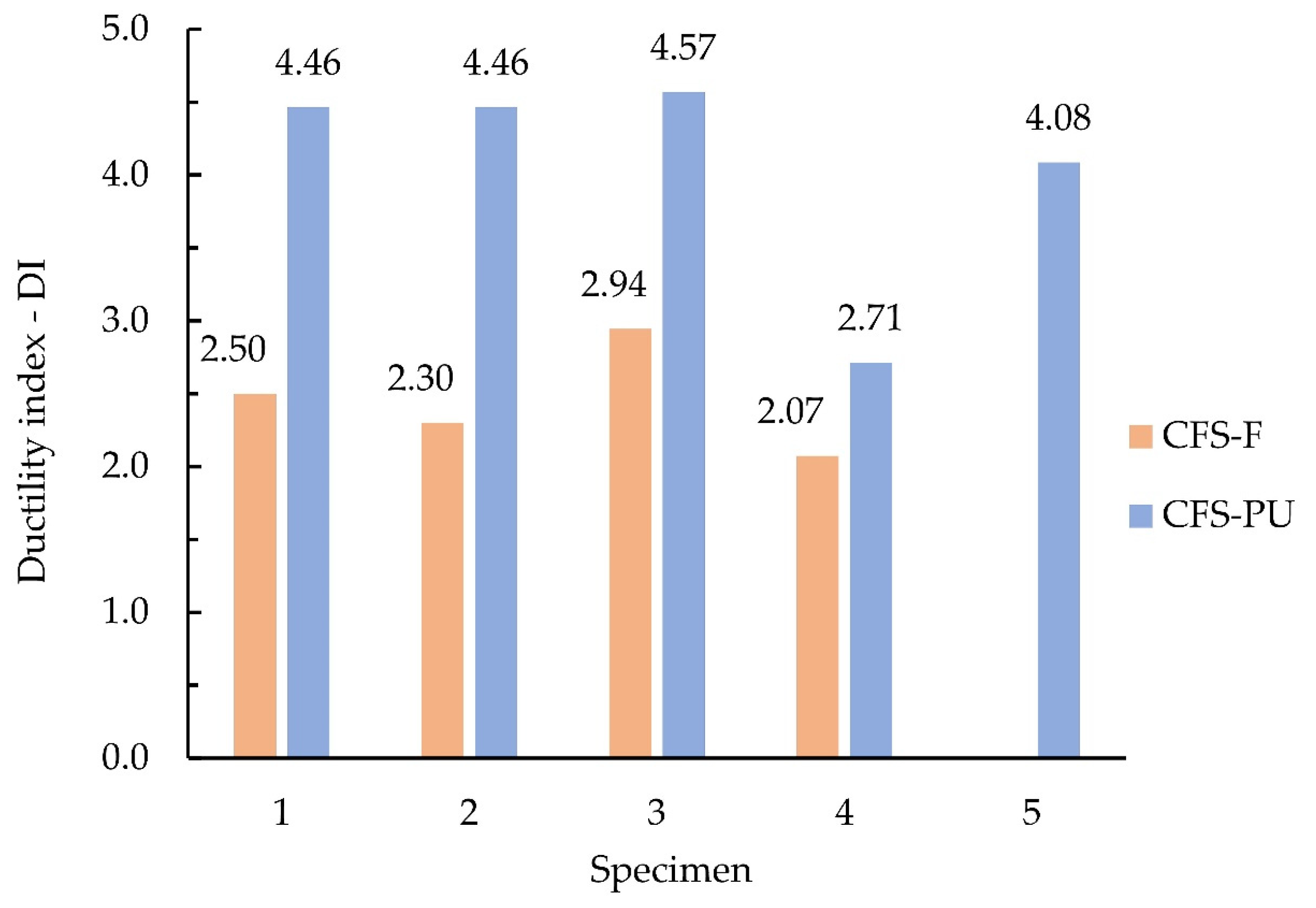
The aim of this work was to present an innovative CFS-PU composite panel and to test its performance under axial compressive loading. According to the currently valid European standards, there are only recommendations from Eurocode 1993-1-3 for the verification of the load-bearing capacity of CFS components in frame construction. However, it is important to note that there are currently no specific standards for determining the load-bearing capacity of structural members braced with sheathing and stiffened with foam, as is the case with the CFS-PU composite wall panel. In the absence of explicit standards, an experimental study was conducted to investigate the performance of the CFS-PU composite wall panel compared to a CFS framed structure. The focus of the study was to evaluate how the presence of PU foam and sheathing affects various aspects, such as the stability of the CFS frame structure, failure modes, load-bearing capacity, and ductility.
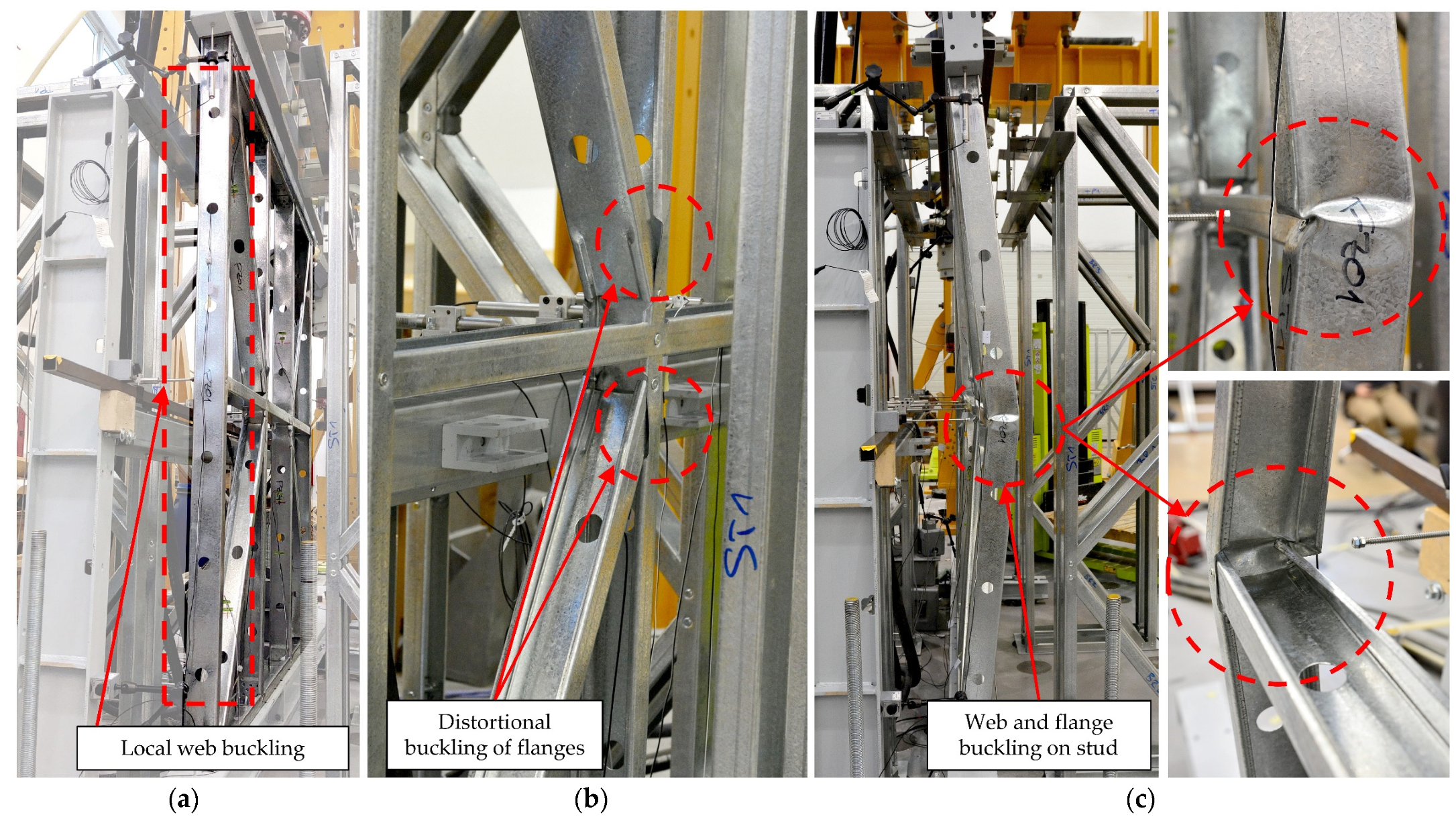
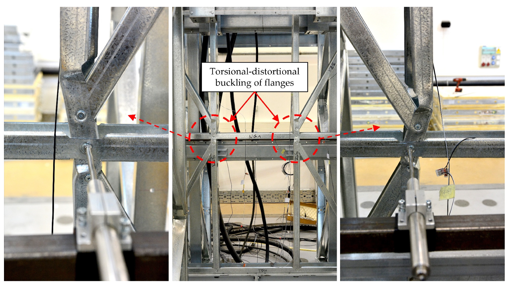
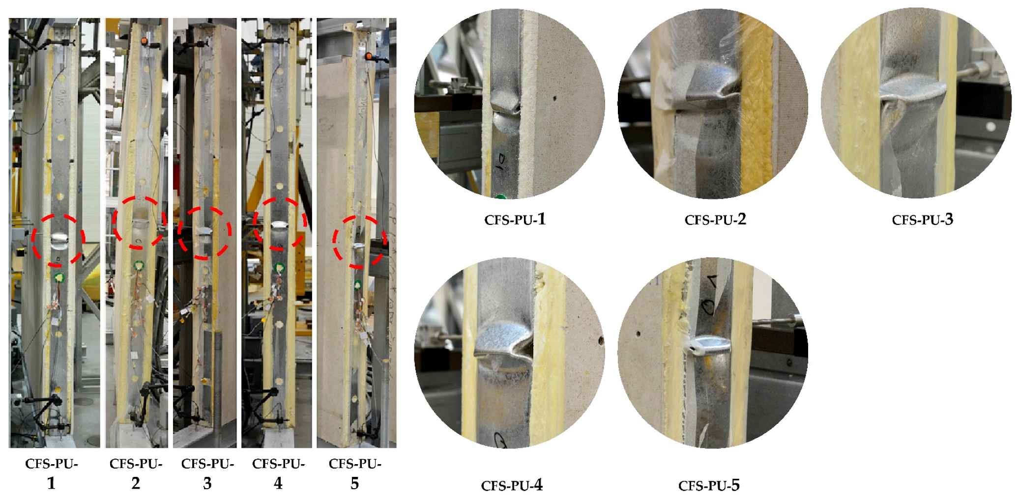
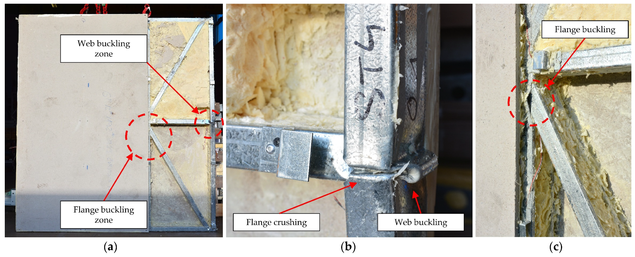
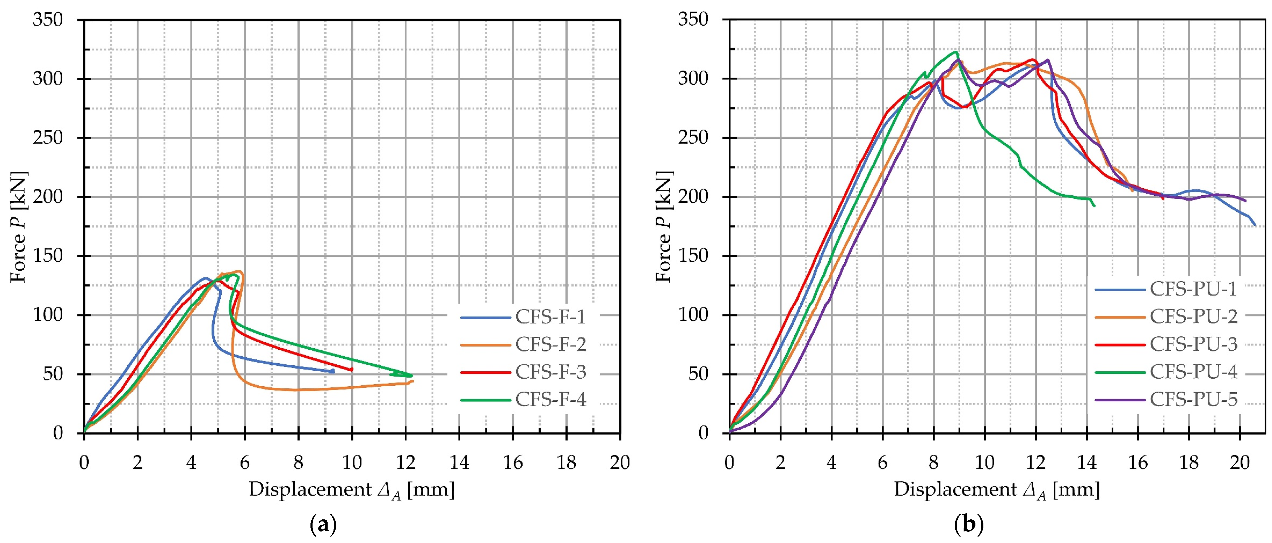
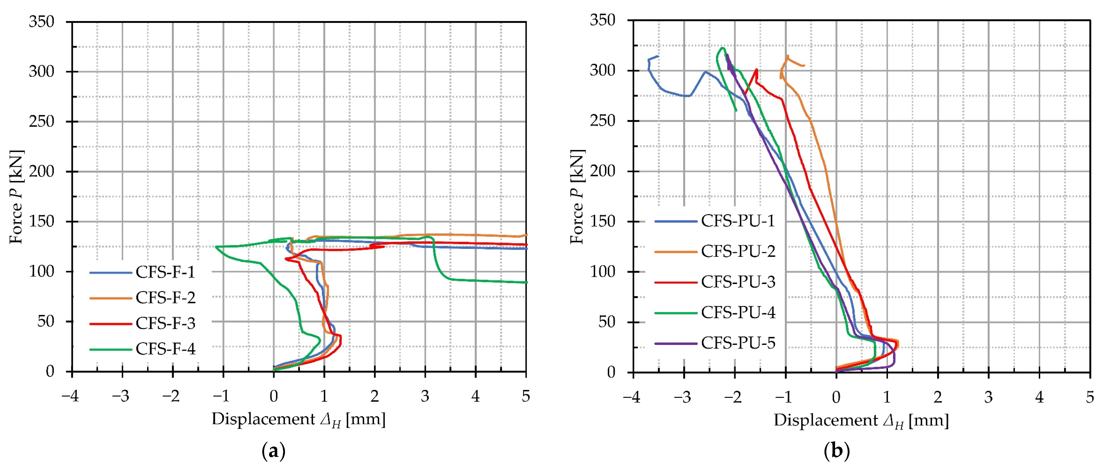
During the tests, at the start of the yielding, the CFS frame specimens experienced local and distortional buckling at the web and flanges of the studs. As it reached its ultimate capacity, a loss in local stability occurred and the entire specimen buckled out of the plane. In contrast, the incorporation of PU foam and sheathing into the CFS-PU test specimens improved their performance by providing additional support to the CFS frame elements. The injected foam, which was distributed throughout the panel, facilitated bonding and interaction between all components, effectively preventing out-of-plane buckling and improving the overall load-bearing capacity of the composite wall panels. The behaviour of the CFS-PU composite panels can be compared with the composite walls described in articles [7,11], where a different infill material was used. All the composite wall panels lost their load-bearing capacity at the limit state of strength failure in the cross-section instead of buckling out-of-plane. The infill material and sheathing had the effect of increasing the load-bearing capacity, stiffness, and ductility.
Although this study provides valuable insights into the behaviour of CFS-PU composite wall panels, it is important to acknowledge its limitations. The main limitation of this study is that it does not provide an evaluation of the individual contributions of foam and sheathing to the stability and load-bearing capacity of the structure. Instead, the results reflect the combined influence of the two materials on the overall performance of the composite wall panel. The results obtained in this study relate only to a specific CFS-PU composite wall panel with specific dimensions. Extrapolation of the results to composite wall panels of other sizes and configurations based solely on this study would be inappropriate. In addition, several imperfections in the wall construction may have influenced the results of the study. These imperfections include lip cuts in the connection area with the nogging, service holes on the web for foam injection, the presence of spacers between the sheathing and the CFS frame, and exterior studs supported by foam on only one side. Furthermore, the distribution of forces in the studs cannot be accurately determined. Approximate distribution values can be considered, but the lack of accurate measurements makes it difficult to fully understand the internal forces and load paths within the composite wall panel.
To investigate the individual contribution of the PU foam and gypsum sheathing to the load-bearing capacity of the CFS-PU composite wall panel, future plans include testing CFS stud walls with different configurations of infill and sheathing. To reduce the influence of imperfections on the results, C-profile studs will be made without lip cuts and service holes on the C-profile web. Strain gauges will be used to obtain more reliable results on the load distribution on the C-profile stud. Furthermore, the goal is to perform a parametric analysis using numerical simulations in order to propose a mathematical model for determining the ultimate strength of the composite CFS-PU wall panel exposed to axial compressive load. In addition, a cost–benefit analysis of CFS-PU composite walls will be carried out to analyse the costs and environmental impact compared to traditional building systems.

5. Conclusions

In this paper, a test programme was presented to investigate the behaviour of the innovative CFS-PU composite wall panel under axial compression. Based on the test results, the following conclusions can be drawn:
(a)
CFS-F specimens without infill and sheathing failed at the yielding, which was characterised by local buckling at the web of the studs, distortional buckling at the stud flanges, and loss in local stability. After reaching the load-bearing capacity, the CFS-F specimens lost almost all of their load-bearing resistance, resulting in out-of-plane buckling of the entire specimen. This failure mode is unpredictable, sudden, and undesirable as it can lead to serious accidents.
(b)
The incorporation of PU foam and sheathing into the CFS-PU specimens significantly improved their performance and provided additional support to the CFS frame elements. Injection of the foam under pressure provided uniform distribution of the foam throughout the panel, resulting in improved bonding and interaction of all panel components. This additional support from the foam and sheathing prevented out-of-plane buckling and improved the overall stability of the composite wall panels.
(c)
CFS-PU specimens experienced local buckling of the web at the outer stud and subsequent flange crushing, as the foam support was limited to one side. Despite these localised failures, the CFS-PU specimens exhibited higher load-bearing capacities and stiffness compared to the CFS-F specimens, with the load-bearing capacity increased by 2.34 times and stiffness by 1.47 times. In addition, the CFS-PU specimens reached a higher force at which yielding occured, indicating a larger elastic zone.
(d)
CFS-PU specimens showed satisfactory resistance and ductility even after failure. The ductility index was 1.65 times higher for the CFS-PU specimens compared to the CFS-F specimens, indicating their ability to withstand loading and absorb energy.
The findings of this study confirm the effectiveness of the CFS-PU composite wall panel design to enhance the CFS frame stability, load-bearing capacity, stiffness, and ductility.

Author Contributions

Conceptualization, A.B., P.K., L.L. and I.P.; methodology, A.B., P.K., L.L. and I.P.; software, A.B. and L.L.; validation, A.B. and L.L.; formal analysis, A.B., P.K. and L.L.; investigation, A.B.; resources, A.B., P.K. and L.L.; data curation, A.B.; writing—original draft preparation, A.B.; writing—review and editing, P.K. and A.B.; visualization, A.B. and L.L.; supervision, P.K.; project administration, P.K.; funding acquisition, P.K. All authors have read and agreed to the published version of the manuscript.

Funding

This research was funded by “Prefabricated buildings of almost zero energy produced in an industrial way”, grant number KK.01.2.1.02.0046, financed from the European Fund for Regional Development with the financial support of the University of Rijeka.

Data Availability Statement

The data presented in this study are available on request from the corresponding author.

Acknowledgments

The authors would like to thank the company Tehnoplast profili d.o.o. and Palijan d.o.o. for their help in producing specimens and test tools.

Conflicts of Interest

The authors declare no conflict of interest.

References

  1. Dubina, D.; Ungureanu, V.; Landolfo, R. Design of Cold-Formed Steel Structures; Wiley: New York, NY, USA, 2012. [Google Scholar] [CrossRef]
  2. Mousavi, S.A.; Zahrai, S.M.; Bahrami-Rad, A. Quasi-static cyclic tests on super-lightweight EPS concrete shear walls. Eng. Struct. 2014, 65, 62–75. [Google Scholar] [CrossRef]
  3. Mydin, A.O.; Wang, Y. Structural performance of lightweight steel-foamed concrete–steel composite walling system under compression. Thin-Walled Struct. 2011, 49, 66–76. [Google Scholar] [CrossRef]
  4. Shannag, M. Characteristics of lightweight concrete containing mineral admixtures. Constr. Build. Mater. 2011, 25, 658–662. [Google Scholar] [CrossRef]
  5. Xu, Z.; Chen, Z.; Osman, B.H.; Yang, S. Seismic performance of high-strength lightweight foamed concrete-filled cold-formed steel shear walls. J. Constr. Steel Res. 2018, 143, 148–161. [Google Scholar] [CrossRef]
  6. Wu, H.; Sui, L.; Wang, J.; Zhou, T. Cycle performance tests and numerical modeling of infilled CFS shear walls. J. Constr. Steel Res. 2020, 168, 106010. [Google Scholar] [CrossRef]
  7. Wang, W.; Wang, J.; Zhao, P.; Ja, L.; Pan, G. Axial compressive experiments and structural behaviour estimation of CFS composite walls sprayed with LPM. J. Build. Eng. 2020, 30, 101305. [Google Scholar] [CrossRef]
  8. Hegyi, P.; Dunai, L. Experimental study on ultra-lightweight-concrete encased cold-formed steel structures Part I: Stability behaviour of elements subjected to bending. Thin-Walled Struct. 2016, 101, 75–84. [Google Scholar] [CrossRef]
  9. Hegyi, P.; Dunai, L. Experimental investigations on ultra-lightweight-concrete encased cold-formed steel structures. Thin-Walled Struct. 2016, 101, 100–108. [Google Scholar] [CrossRef]
  10. Wu, H.; Chao, S.; Zhou, T.; Liu, X. Cold-formed steel framing walls with infilled lightweight FGD gypsum Part I: Cyclic loading tests. Thin-Walled Struct. 2018, 132, 759–770. [Google Scholar] [CrossRef]
  11. Wu, H.; Chao, S.; Zhou, T.; Liu, Y. Cold-formed steel framing walls with infilled lightweight FGD gypsum Part II: Axial compression tests. Thin-Walled Struct. 2018, 132, 771–782. [Google Scholar] [CrossRef]
  12. von der Heyden, A.; Lange, J. Buckling behaviour of polyurethane foam-filled cold-formed steel C-sections. In Proceedings of the 20th International Conference on Composite Materials (ICCM20), Copenhagen, Denmark, 19–24 July 2015. [Google Scholar]
  13. Sagadevan, R.; Rao, B. Experimental and analytical study on structural performance of polyurethane foam-filled built-up galvanized iron members. Thin-Walled Struct. 2020, 146, 106446. [Google Scholar] [CrossRef]
  14. Miller, H.T.; Pekoz, T. Behavior of Cold-Formed Steel Wall Stud Assemblies. J. Struct. Eng. 1993, 119, 641–651. [Google Scholar] [CrossRef]
  15. Miller, H.T.; Pekoz, T. Behavior of Gypsum-Sheathed Cold-Formed Steel Wall Studs. J. Struct. Eng. 1994, 120, 1644–1650. [Google Scholar] [CrossRef]
  16. Tian, Y.; Wang, J.; Lu, T.; Barlow, C. An experimental study on the axial behaviour of cold-formed steel wall studs and panels. Thin-Walled Struct. 2004, 42, 557–573. [Google Scholar] [CrossRef]
  17. Tian, Y.; Wang, J.; Lu, T. Axial load capacity of cold-formed steel wall stud with sheathing. Thin-Walled Struct. 2007, 45, 537–551. [Google Scholar] [CrossRef]
  18. Wang, J.; Tian, Y.; Lu, T. The role of frame members and sheathing in partition wall panels subjected to compression. Thin-Walled Struct. 2005, 43, 983–1002. [Google Scholar] [CrossRef]
  19. Vieira, L.; Shifferaw, Y.; Schafer, B. Experiments on sheathed cold-formed steel studs in compression. J. Constr. Steel Res. 2011, 67, 1554–1566. [Google Scholar] [CrossRef]
  20. Vieira, L.C.; Schafer, B.W. Lateral stiffness and strength of sheathing braced cold-formed steel stud walls. Eng. Struct. 2012, 37, 205–213. [Google Scholar] [CrossRef]
  21. Vieira, L.C.M.; Shifferaw, Y. Behavior and Design of Sheathed Cold-Formed Steel Stud Walls under Compression. J. Struct. Eng. 2013, 139, 772–786. [Google Scholar] [CrossRef] [Green Version]
  22. Ye, J.; Feng, R.; Chen, W.; Liu, W. Behavior of cold-formed steel wall stud with sheathing subjected to compression. J. Constr. Steel Res. 2016, 116, 79–91. [Google Scholar] [CrossRef]
  23. Sonkar, C.; Mittal, A.K.; Bhattacharyya, S.K. Comparative Study on Cold-Formed Steel Single-Stud and Multiple-Studs Wall Panels with Magnesium Oxide Sheathing under Axial Loading: Experimental and Analytical. J. Struct. Eng. 2020, 146, 04020224. [Google Scholar] [CrossRef]
  24. Sani, M.S.H.M.; Muftah, F.; Tan, C.S. Experimental Analysis of Cold-Formed Steel C-Sections with the Notch Subjected to Axial Compression. KSCE J. Civ. Eng. 2020, 24, 1228–1239. [Google Scholar] [CrossRef]
  25. Zhang, X.; Zhang, E.; Li, C. Study on axial compression mechanical behavior of cold-formed thin-walled C-shaped steel composite wall sheathed with straw board on both sides. Structures 2021, 33, 3746–3756. [Google Scholar] [CrossRef]
  26. Sonkar, C.; Bhattacharyya, S.K.; Mittal, A.K. Investigations on cold-formed steel wall panels with different sheathing boards under axial loading: Experimental and analytical/semi-analytical studies. J. Build. Eng. 2021, 44, 102924. [Google Scholar] [CrossRef]
  27. Mowrtage, W.; Yel, N.H.; Pekmezci, B.; Atahan, H.N. Load carrying capacity enhancement of cold formed steel walls using shotcreted steel sheets. Thin-Walled Struct. 2012, 60, 145–153. [Google Scholar] [CrossRef]
  28. Lukačević, L.; Krolo, P.; Bakran, A. Experimental Investigation of Face-to-Core Bond Strength between Gypsum Fibreboard and PU Rigid Foam. In Proceedings of the 10th International Congress of Croatian Society of Mechanics, Pula, Croatia, 28–30 September 2022; pp. 197–198. [Google Scholar]
  29. Lukačević, L.; Krolo, P.; Čeh, N. Ispitivanje kompozitnog panela na savijanje s ciljem utvrđivanja svojstva prionjivosti obloge i jezgre panela (eng. Bending test on a composite panel with the aim of determining the adhesion properties of the sheathing and the core). In Proceedings of the 11th Congress of Croatian Society of Mechanics, Pula, Croatia, 27–29 September 2021; pp. 165–171. [Google Scholar]
  30. ISO 6892-1:2019; Metallic Materials—Tensile Testing—Part 1: Method of Test at Room Temperature. The International Organization for Standardization: Geneva, Switzerland, 2019.
  31. Lukačević, L.; Krolo, P.; Bakran, A. Experimental Investigation of Novel Angle Bracket Connection in Cold-Formed Steel Structures. Buildings 2022, 12, 1115. [Google Scholar] [CrossRef]
  32. ISO 844:2021; Rigid Cellular Plastics—Determination of Compression Properties. The International Organization for Standardization: Brussels, Belgium, 2014.
Figure 1. Configuration of CFS-PU composite wall.
Buildings 13 01897 g001
Figure 2. Geometry of the CFS frame with the associated details of joints (mm).
Buildings 13 01897 g002
Figure 3. Position of the angle brackets, spacers, and service holes on the CFS frame with details of (a) spacers and service holes on CFS frame, (b) frame with sheathings, and (c,d) details of angle bracket mounted on the frame stud (mm).
Buildings 13 01897 g003
Figure 4. CFS-PU composite wall panel specimen with sheathings and PU foam filling.
Buildings 13 01897 g004
Figure 5. PU foam filling process: (a) specimen under press and (b) PU foam injection phases.
Buildings 13 01897 g005
Figure 6. Stress–strain curves for (a) S550 GD and DX51D-Z275 steel, and (b) PU foam.
Buildings 13 01897 g006
Figure 7. Test setup for CFS-PU composite wall panel testing with details of specimen anchoring to the reaction beams.
Buildings 13 01897 g007
Figure 8. The position of the LVDTs.
Buildings 13 01897 g008
Figure 9. Failure modes during test: (a) local web buckling, (b) distortional flange buckling, and (c) web and flange buckling after loss of stability.
Buildings 13 01897 g009
Figure 10. Failure modes as torsional-displacement buckling of inner studs.
Buildings 13 01897 g010
Figure 11. Failure modes of CFS-PU specimens with details of web buckling.
Buildings 13 01897 g011
Figure 12. Failure modes of CFS-PU specimens with details of (a) bond failure between foam and sheathings and (b) cavity forming in the spacers area.
Buildings 13 01897 g012
Figure 13. Failure mode of (a) CFS-PU-5 specimen with details of (b) web buckling and (c) flange buckling.
Buildings 13 01897 g013
Figure 14. Force–displacement (P-A) curves of (a) CFS-F and (b) CFS-PU specimens.
Buildings 13 01897 g014
Figure 15. Force–displacement ( P H ) curves of (a) CFS-F and (b) CFS-PU specimens.
Buildings 13 01897 g015
Figure 16. Ductility index for CFS-F and CFS-PU specimens.
Buildings 13 01897 g016
Table 1. Geometric sizes of the specimens with calculated PU foam density.
SpecimenWidth (mm)Height (mm)Thickness (mm)Weight (kg)PU Foam Density (kg/m3)
wTwBhLhRtTtBtLtR
CFS frame
CFS-F-118001799200020008930.06-
CFS-F-2180118002000199930.02-
CFS-F-3179917981999200030.02-
CFS-F-4179918001997200029.98-
CFS-PU composite wall panel
CFS-PU-11796179620032001156159160157165.8346.08
CFS-PU-21798180319962005158158158158165.0744.38
CFS-PU-31800179920032002156158156158165.0144.57
CFS-PU-41798179920042003156157158159164.1042.49
CFS-PU-51799180420032000160158159158166.5047.06
Table 2. Results of tensile tests for S550 GD and DX51D Z275 [31].
Material   E   ( M P a )   R e H   ( M P a )   R m   ( M P a )   A e   ( % )   A g t   ( % )   A t   ( % )
S550 GD183,737697.22704.980.397.418.89
DX51D194,295375.78414.070.1913.3326.44
Table 3. Results of uniaxial compression test for PU foam.
Specimen   A 0   m m 2   h 0   m m   ρ   k g / m 3   σ m   M P a   ε m   %   E   M P a
F45-199455049.550.3786.0608.536
F45-299584949.180.4075.6248.575
F45-399135049.480.4014.34311.716
F45-499375049.270.3564.38511.438
F45-599025049.490.3735.0949.884
F45-MV (Average)99315049.390.385.1010.03
Relative Standard Deviation0.23%0.85%0.33%5.46%14.80%15.11%
Table 4. Results of axial compression test for CFS-F specimens.
Specimen   P   k N   A   m m   K C   k N / m m   W   ( J )
CFS-F-1131.074.5332.24333.91
CFS-F-2136.975.7630.29404.52
CFS-F-3129.104.9833.05356.94
CFS-F-4134.075.5631.35391.67
CFS-F (Average)132.805.2131.73371.76
Relative Standard
Deviation
2.60%10.70%3.74%8.68%
Table 5. Results of axial compression test for CFS-PU specimens.
SpecimenWeb BucklingFlange Crushing   K C   M P a
  P W   k N   A w   m m   W w   J   P F   k N   A F   m m   W F   J
CFS-PU-1298.188.071320.84314.2712.492616.8750.83
CFS-PU-2315.049.111450.17313.0410.922009.5643.10
CFS-PU-3301.358.291448.67316.0511.912522.5046.18
CFS-PU-4322.378.871487.79322.378.871487.7948.37
CFS-PU-5315.828.991310.28315.6512.492363.8645.36
CFS-PU (Average)310.558.661403.55314.7511.952378.2046.77
Relative Standard Deviation3.32%5.28%5.84%0.44%6.20%11.23%6.31%
Disclaimer/Publisher’s Note: The statements, opinions and data contained in all publications are solely those of the individual author(s) and contributor(s) and not of MDPI and/or the editor(s). MDPI and/or the editor(s) disclaim responsibility for any injury to people or property resulting from any ideas, methods, instructions or products referred to in the content.

