Article

Influence of Intermediate Stiffeners on Axial Capacity of Thin-Walled Built-Up Open and Closed Channel Section Columns

by
Beulah Gnana Ananthi Gurupatham
1,
Krishanu Roy
2,*,
Gary M. Raftery
3 and
James Boon Piang Lim
2
1
Department of Civil Engineering, Anna University, Chennai 600025, India
2
School of Engineering, Civil Engineering, The University of Waikato, Hamilton 3216, New Zealand
3
Department of Civil and Environmental Engineering, Faculty of Engineering, The University of Auckland, Auckland 1023, New Zealand
*
Author to whom correspondence should be addressed.
Buildings 2022, 12(8), 1071; https://doi.org/10.3390/buildings12081071
Submission received: 26 June 2022 / Revised: 16 July 2022 / Accepted: 18 July 2022 / Published: 22 July 2022
(This article belongs to the Special Issue Cold-Formed Steel Structures)

Abstract

:
This paper investigates the post-buckling behaviour and axial capacity of thin-walled steel stiffened single-channel sections (ISSCS) and back-to-back stiffened channel sections (BISCS). BISCS were connected using fasteners at a spacing of 200 mm and with an edge distance of 100 mm. Under axial compression, 10 new ISSCS and BISCS columns with fixed-ended conditions were tested. In the experimental tests, the back-to-back channel sections failed due to a combination of local and global buckling, whereas the single-channel sections generally failed as a result of local buckling. The behaviour of both ISSCS and BISCS shows a 20% increase on an average in axial capacity through adding stiffeners at the junction of the flange and the web, in addition to stiffeners in the web. A nonlinear finite element model (FEM) with material and geometric nonlinearities was then developed. The FE model was validated against the experimental results. A comprehensive parametric study comprising 64 face-to-face intermediate stiffened channel sections (FISCS) was then conducted to study the influence of stiffener length on its axial capacity. The axial capacity obtained from the tests and FEA shows that design in accordance with the Direct Strength Method (DSM) is accurate and conservative by only 4% on average.

1. Introduction

Built-up cold-formed steel (CFS) sections have become more popular recently when used as structural members. Advantages associated with such members include improved strength-to-self weight ratios, structurally efficient cross-sectional shapes, and cost-effective design. CFS angle, zed, and hat sections are becoming increasingly popular in trusses, transmission towers, and portal frames [1,2,3,4,5]. Significant research on single and built-up CFS channel sections is available in the literature [6,7,8,9,10,11,12]. CFS members with openings are increasingly used to facilitate ease of service in buildings [13,14,15,16]. Individual CFS sections are manufactured in a variety of shapes, and the profiles are stiffened with intermediate and edge stiffeners.
The use of built-up sections by joining one or more geometrical CFS cross-section has also become popular. Because combining CFS sections reduces global slenderness while increasing the stiffness of individual cross-sectional components, the axial compression strength of the built-up CFS column is typically greater than the sum of the axial strengths of the individual members. CFS members in which an intermediate stiffener is included in single-channel sections (ISSCS), back-to-back channel sections incorporating an intermediate stiffener (BISCS), and face-to-face channel sections with an intermediate stiffener (FISCS), which can be used to carry larger compressive loads, are considered in this paper. These CFS-built-up channel sections can be used as columns in portal frames to improve lateral stability.
Figure 1a–l summarise the CFS built-up columns investigated in the literature [17,18,19,20,21,22,23,24,25,26,27,28,29,30,31]. The built-up members can be categorized as open or closed. Closed sections have a higher torsional rigidity [19,26,27,28,32,33,34]. However, their disadvantage is that there are no particular codified provisions in the design standards. As a result, many researchers have proposed new equations. The use of a modified slenderness technique to design the longitudinal spacing of fasteners in built-up CFS channel sections is recommended by the American Iron and Steel Institute (AISI [35]) and Australian and New Zealand Standards (AS/NZS [36]) and summarised in Section 4 of this paper. This is the case whether using the Effective Width Method (EWM) or the Direct Strength Method (DSM). Different cross-sections of CFS built-up sections under axial compression are available in the literature (Craveiro et al. [17], Nie et al. [18], Anbarasu [19], Zhou et al. [20], Roy et al. [21,22], Ananthi et al. [23] and Chi et al. [37]).
Many studies on single- and double-channel sections have been investigated by previous researchers [38,39,40,41]. Roy et al. [25] recently examined the effect of screw spacing on the axial strength of back-to-back built-up CFS un-lipped channel sections, demonstrating that AISI [35] and AS/NZS [36] can be un-conservative for stub and short columns. Whittle and Ramseyer [42] investigated the axial strength of welded toe-to-toe CFS built-up channel sections. Piyawat et al. [43] looked at welded channels that are joined back-to-back.
The compressive behaviour of compound double-box columns with two C-shaped and two U-shaped CFS channel sections was investigated by Nie et al. [18]. Even if the predicted eccentric axial compression strengths are conservative, the “Effective Ratio of Width-to-Thickness Method,” “EWM,” and “DSM” were all found to be able to predict the axial compressive strengths of the built-up columns. Roy et al. [21] considered the axial capacities of CFS built-up box sections both experimentally and numerically. For compound box sections, the axial design strength calculations based on the American Iron and Steel Institute (AISI [35]) and the Australian and New Zealand Standards (AS/NZS [36]) were found to be 17% conservative on average. Liao et al. [44] evaluated the axial capacity of multi-limb CFS built-up stub columns and found that screw spacing did not affect the ultimate axial compressive capacity and buckling capacity of such multi-limb CFS built-up stub columns. Lu et al. [45] experimented with and established a novel DSM approach for the design of CFS built-up I-section columns.
The use of stainless steel for built-up channels has become more popular in recent years, with the use of stainless steel in structural applications also increasing. Roy et al. [46,47,48] and Ananthi et al. [49] considered cold-formed stainless steel built-up channels under axial compression. Yousefi et al. [50] numerically studied lipped channels with web openings for web crippling under the interior-two-flange loading condition.
Ananthi et al. [3] and Aruna et al. [51,52] investigated the influence of stiffeners on cold-formed steel angle sections. The CFS built-up open sections with edge and longitudinal web stiffeners in cold-formed steel channel sections were investigated by Zhang and Young [26,27,28]. It was found that the modified direct strength approach was able to predict the ultimate load of open section columns. Young and Chen [32] used experimental and numerical investigations to study the design of CFS built-up closed sections with intermediate stiffeners. Press-braked high-strength steel sections were used for build-up sections. In DSM calculations for closed built-up sections, with single sections used to calculate the buckling stresses, it was found that the design calculations were conservative and reliable.
Ananthi et al. [53] considered a built-up column consisting of four individual CFS lipped channels, two of them placed back-to-back at the web using two self-drilling screw fasteners at a specified spacing along the column length, while the other two channels were connected flange-to-flange using a self-drilling screw fastener at a specified spacing along the column length. Using both the experimental and FE results, it was found that design in accordance with the American Iron and Steel Institute (AISI [35]) and the Australian and New Zealand Standards (AS/NZS [36]) were 6% conservative on average when used to determine the axial capacity of a back-to-back and flange-to-flange built-up CFS channel section. Phan et al. [31] experimentally tested CFS built-up channel sections and established a design procedure for built-up sections that failed due to flexural-torsional buckling. Built-up CFS sections with different profiles were investigated by Deepak and Ananthi [54], Aghoury et al. [55], Anbarasu [56,57], Dar et al. [58,59,60], Fang et al. [61,62], Chen et al. [63], Lawson et al. [64], and Roy et al. [65].
It can be seen from the literature that there has been little research on the topic of built-up thin-walled channels that includes multiple stiffeners subject to compression. The behaviour of both plain and lipped ISSCS, BISCS, and FISCS columns under axial compression is considered in this paper. As mentioned previously, this paper reports the results of 10 new CFS single ISSCS and built-up BISCS channel section columns with the top end of the column as fixed and the bottom end with a translational degree of freedom along the vertical axis. All test specimens were press-braked from cold-rolled low tensile structural steel sheets. BISCS were connected using fasteners spaced at 200 mm and with an edge distance of 100 mm. The length of each column was 1600 mm. A non-linear finite element (FE) model was then developed, including material non-linearity and initial geometric imperfections. The FE model was validated against the experimental results, both in terms of axial strength and deformed shapes. Using the validated FE model, a parametric study involving a total of 64 welded face-to-face intermediate stiffened channel sections (FISCS) was conducted. In the parametric study, the provision of stiffeners on the plain and lipped sections, four grades of steel, and lengths of columns on their axial capacity were investigated. Axial capacities obtained from the experimental tests and FEA were used to assess the performance of current design guidelines as per the Direct Strength Method (DSM).
Figure 1. Cross-sections of CFS built-up channel sections from the literature. (a)H.D. Craveiro et al. [17] and Nie et al. [18]. (b) Anbarasu M [19]. (c) Zhou X et al. [20]. (d) Roy et al. [21]. (e) Roy et al. [22]. (f) Ananthi and Ashvini [23]. (g) Roy et al. [24]. (h) Roy et al. [25]. (i) J. Zhang, B. Young [26,27,28]. (j) Ananthi et al. [29]. (k) Y.Q. Li et al. [30]. (l) Phan et al. [31].
Buildings 12 01071 g001aBuildings 12 01071 g001bBuildings 12 01071 g001c

2. Experimental Program

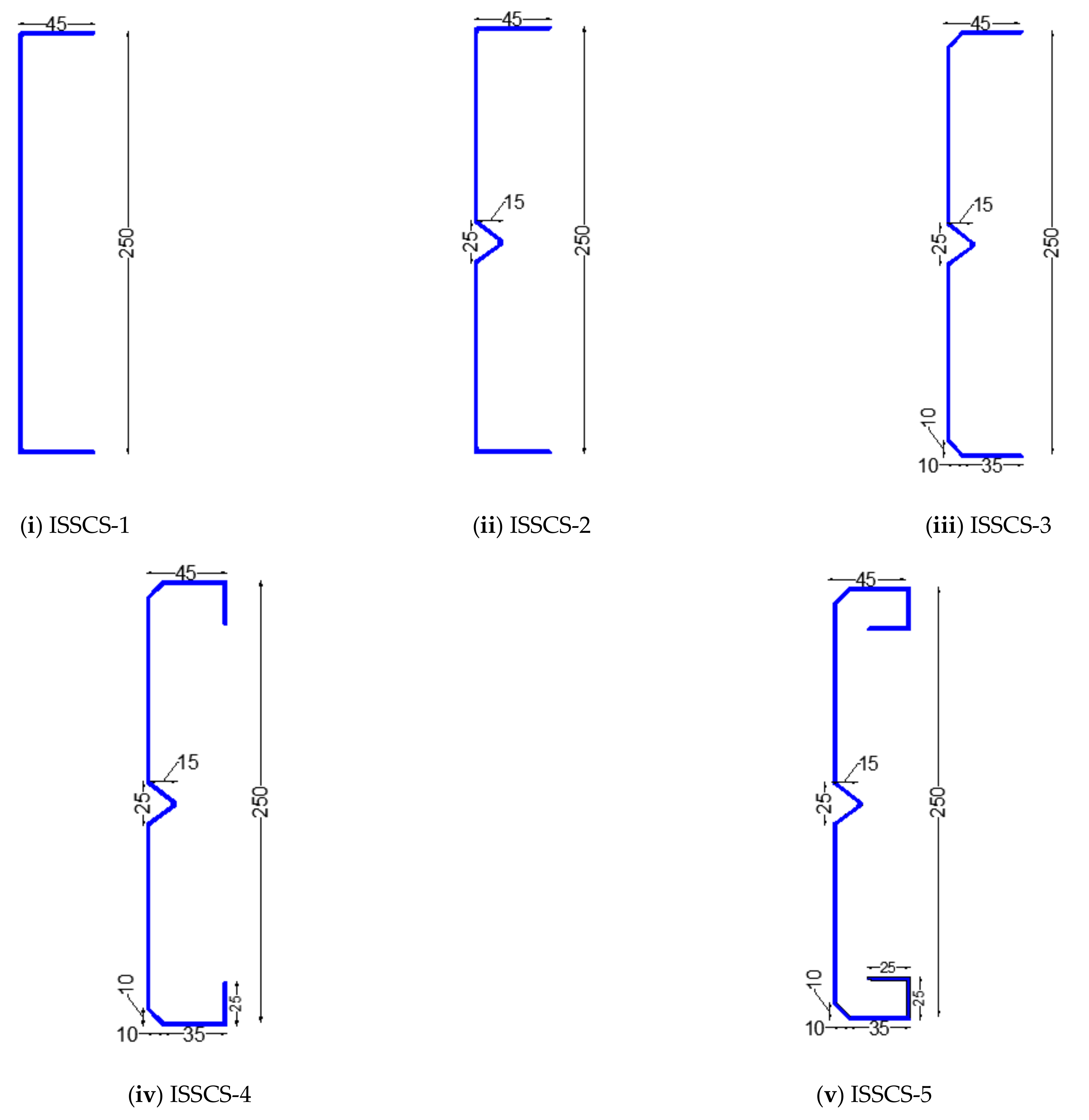
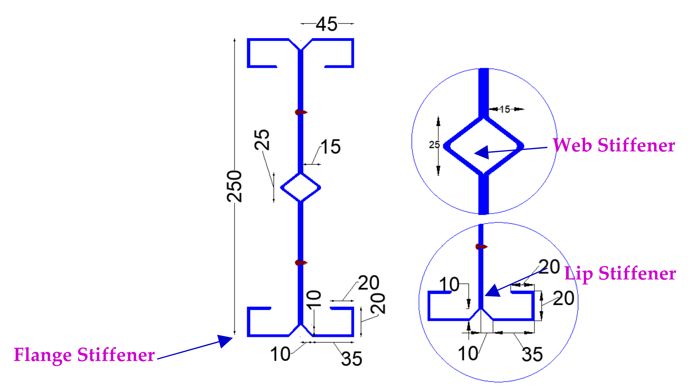
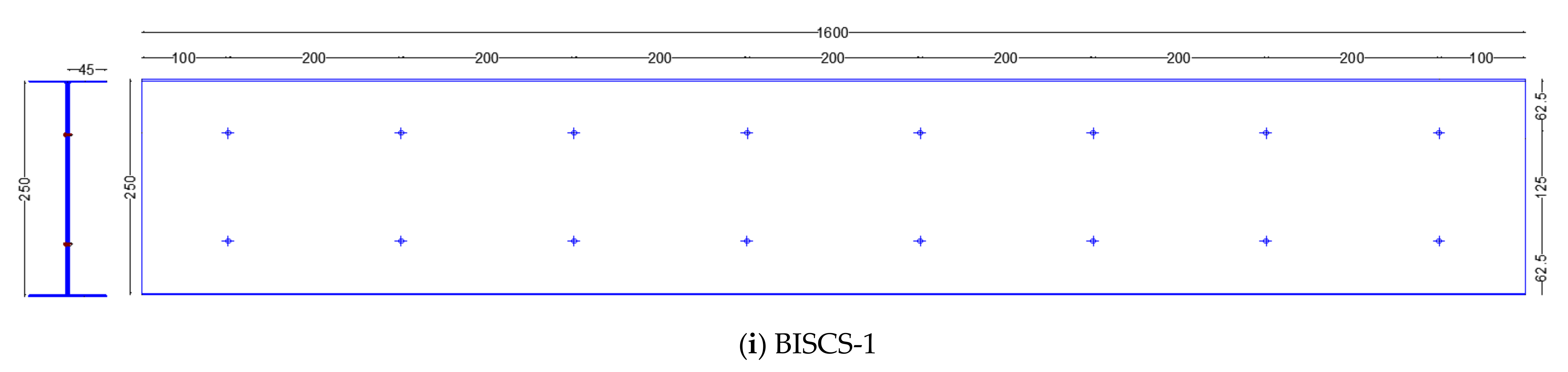
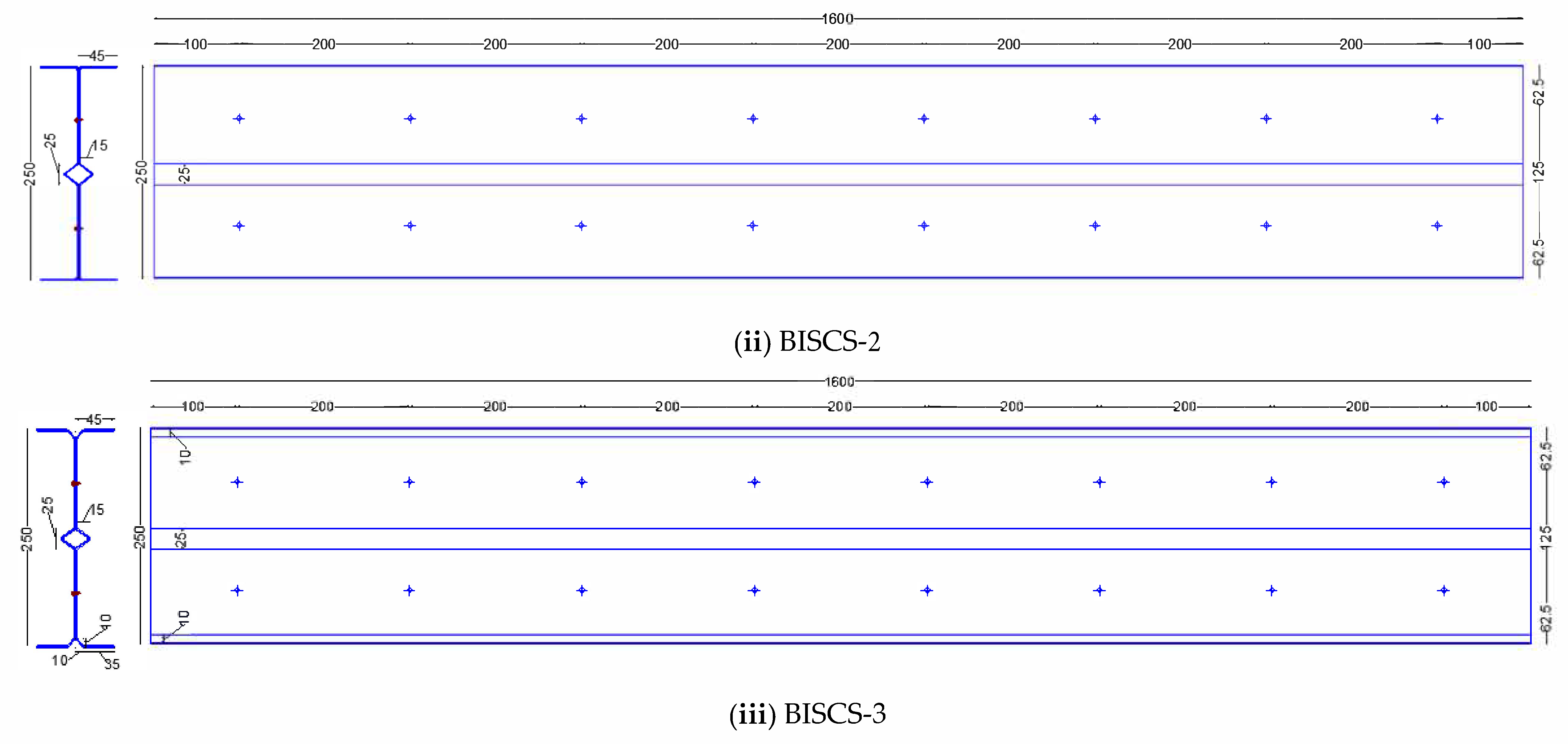
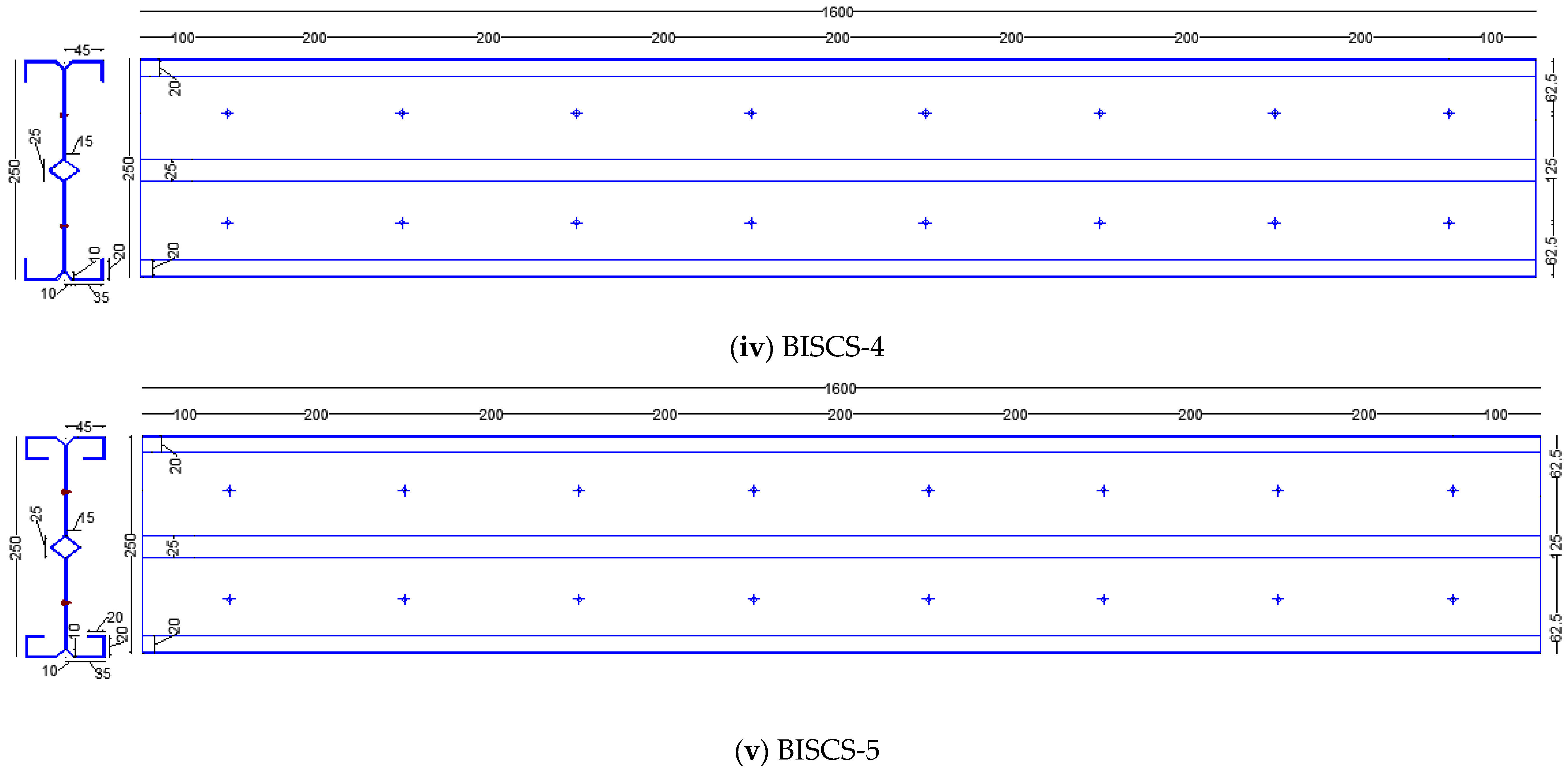
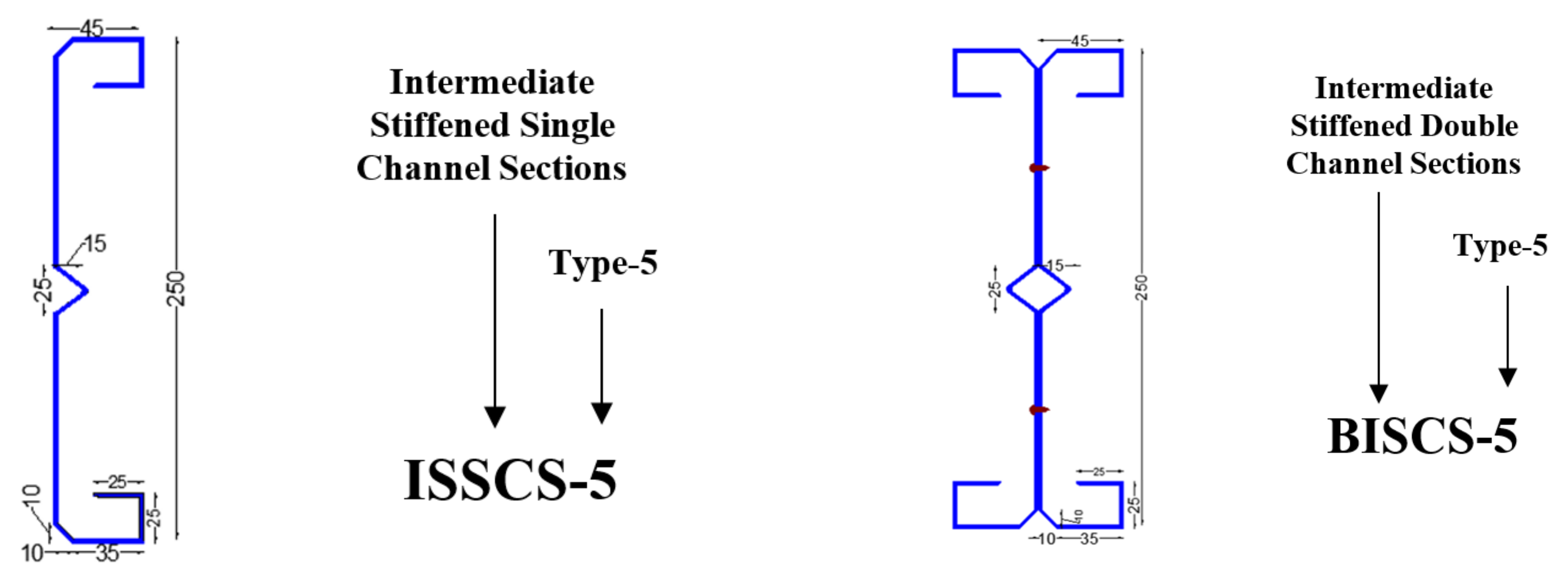
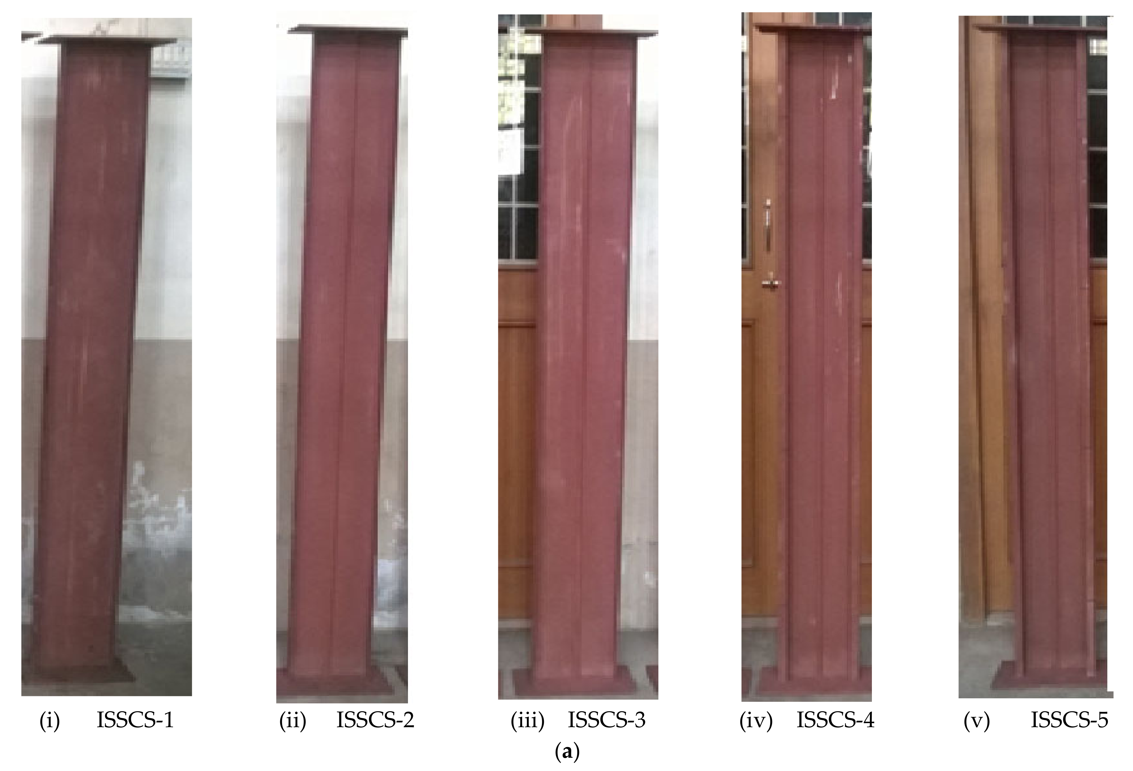
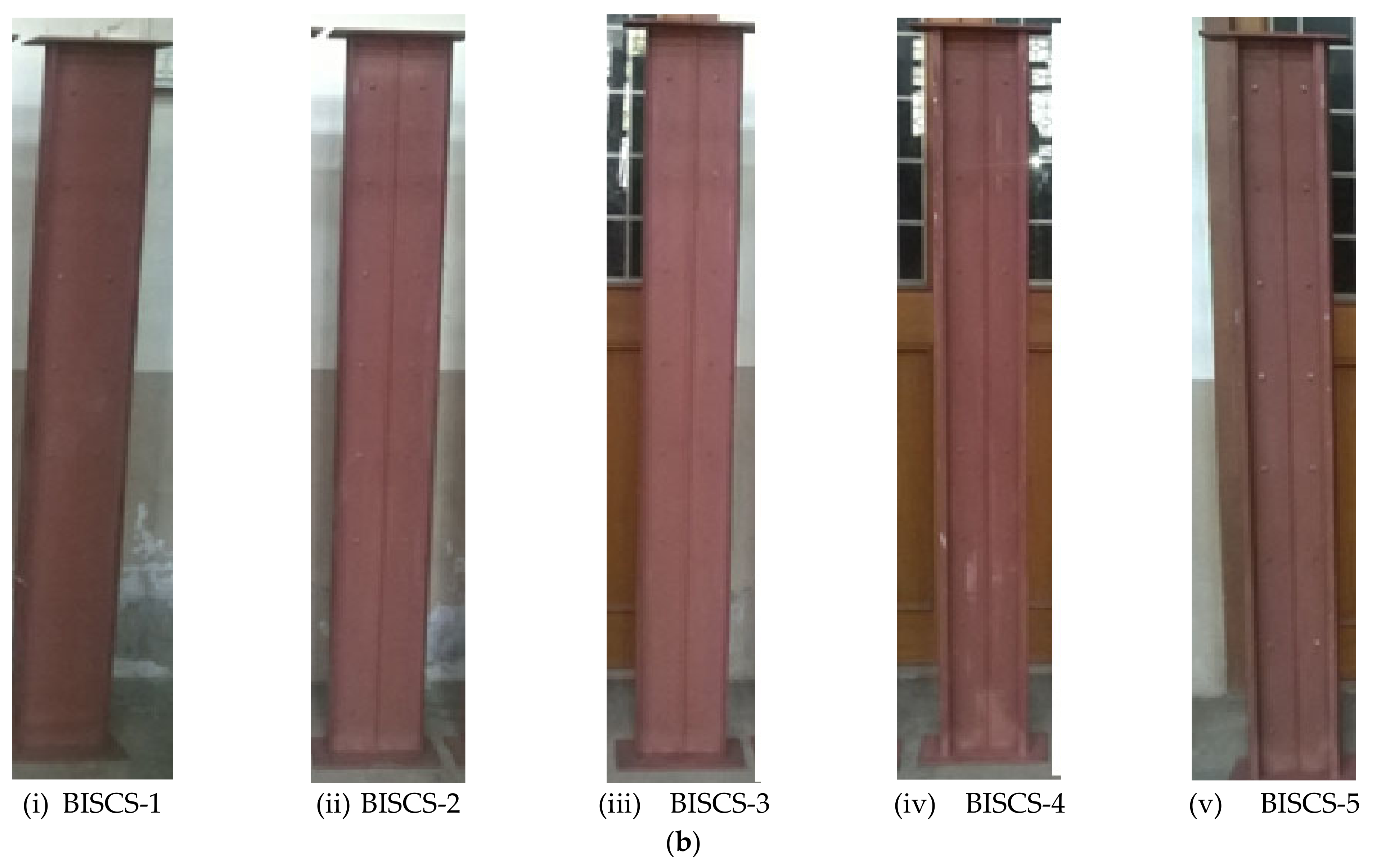
2.1. Specimens Examined

The test specimens chosen for the experimental studies were press-braked from cold-rolled low tensile structural steel sheets with a thickness of 1.6 mm. The sections had a web depth of 250 mm, a flange width of 45 mm, a lip length of 20 mm, and a base-metal thickness of 1.6 mm. Figure 2, Figure 3 and Figure 4 show the cross-sectional details of the plain and lipped stiffened ISSCS and BISCS channel sections considered in the experimental program. The length of each column was 1600 mm. The built-up column consisted of two individual CFS channels connected back-to-back using two rows of self-drilling screw fasteners with an edge distance of 100 mm and an intermediate spacing of 200 mm. Figure 4 shows the arrangement of the fasteners longitudinally. The edge distance and the connector spacing were designed as per the rules of AISI [35]. The fastener spacing was calculated to meet the spacing requirements of the CFS built-up columns as specified in Chapter J of the AISI [35] specification.

2.2. Specimen Labelling for the Experimental Program

The specimens labelled for the experimental studies (ISSCS and BISCS) are shown in Figure 5. The type of section, section geometry, and the positioning of the stiffeners are explained below.
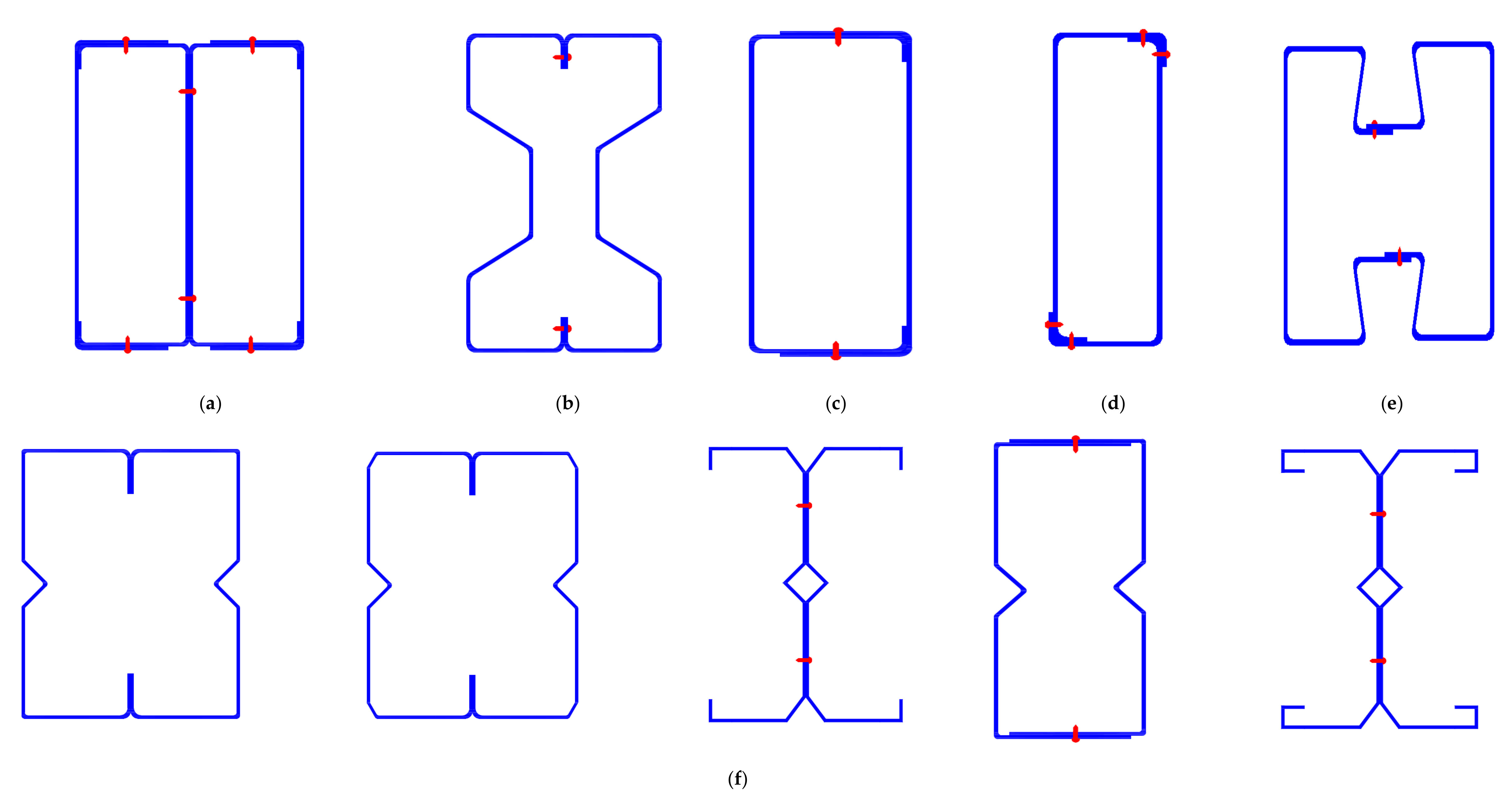
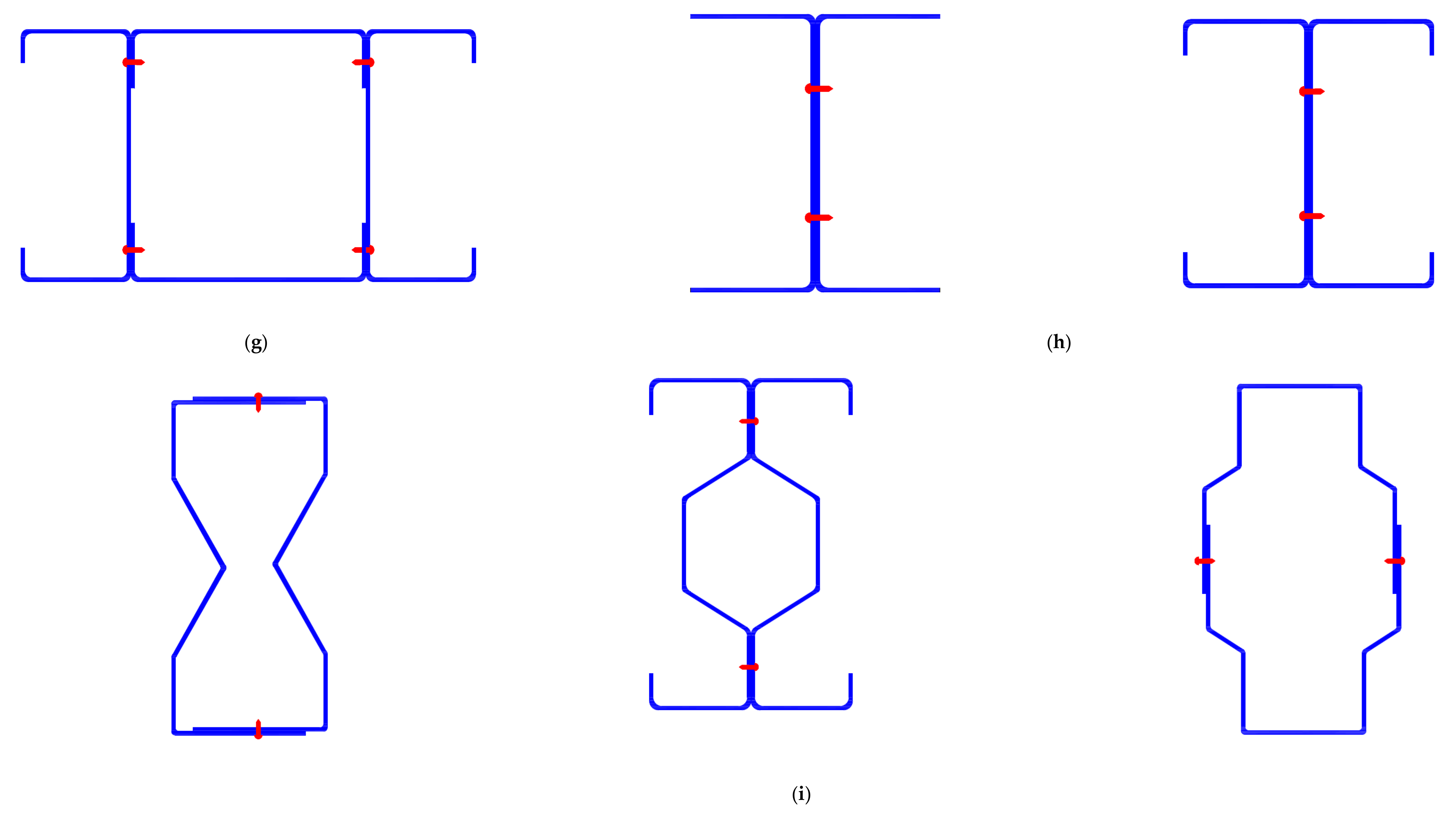
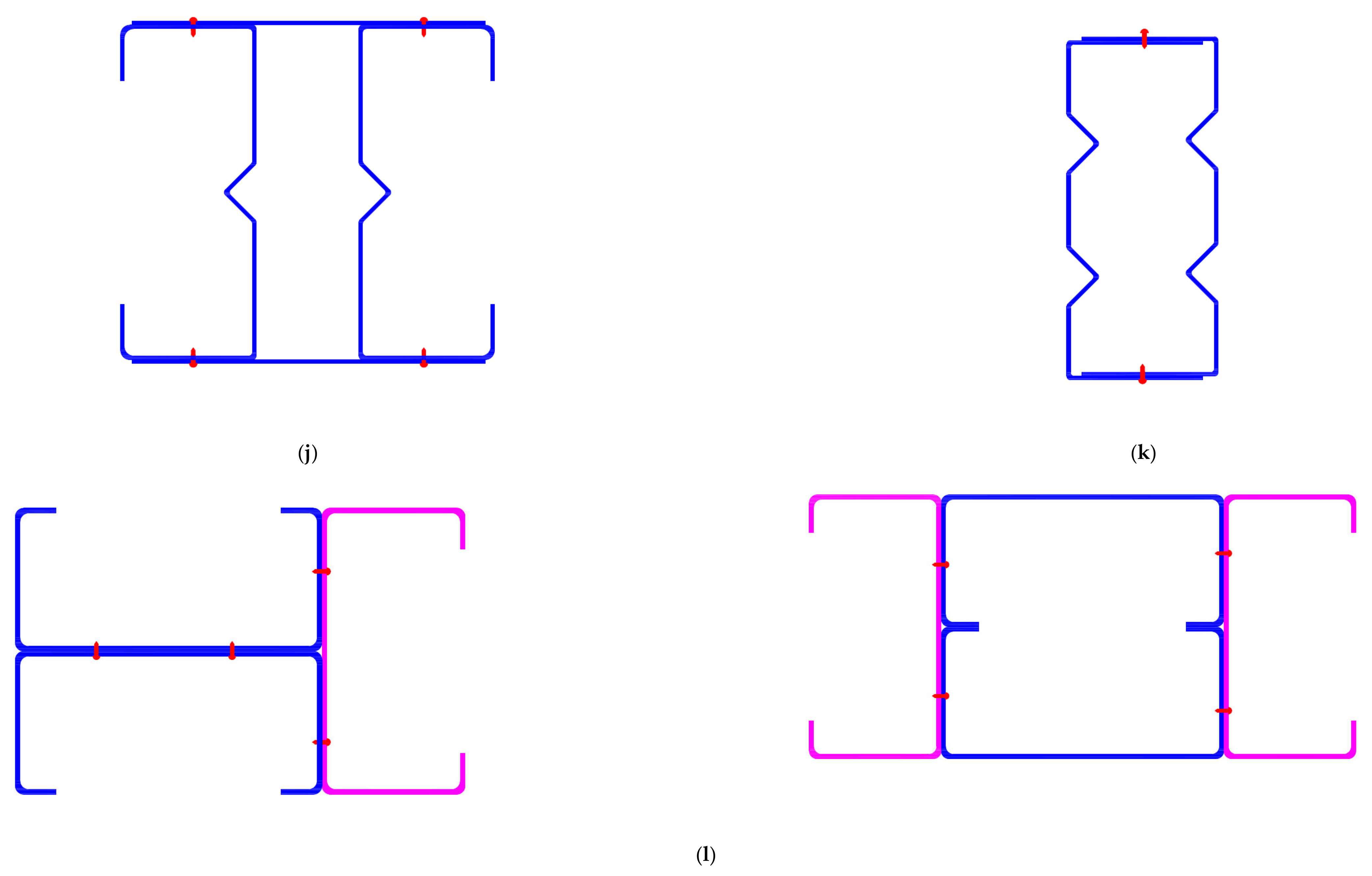
  • “Type-1” indicates plain CFS channel columns with no stiffeners.
  • “Type-2” indicates plain CFS channel columns with intermediate web stiffeners.
  • “Type-3” indicates plain CFS channel columns with both intermediate web stiffeners and flange stiffeners.
  • “Type-4” indicates lipped CFS channel columns with both intermediate web stiffeners and flange stiffeners.
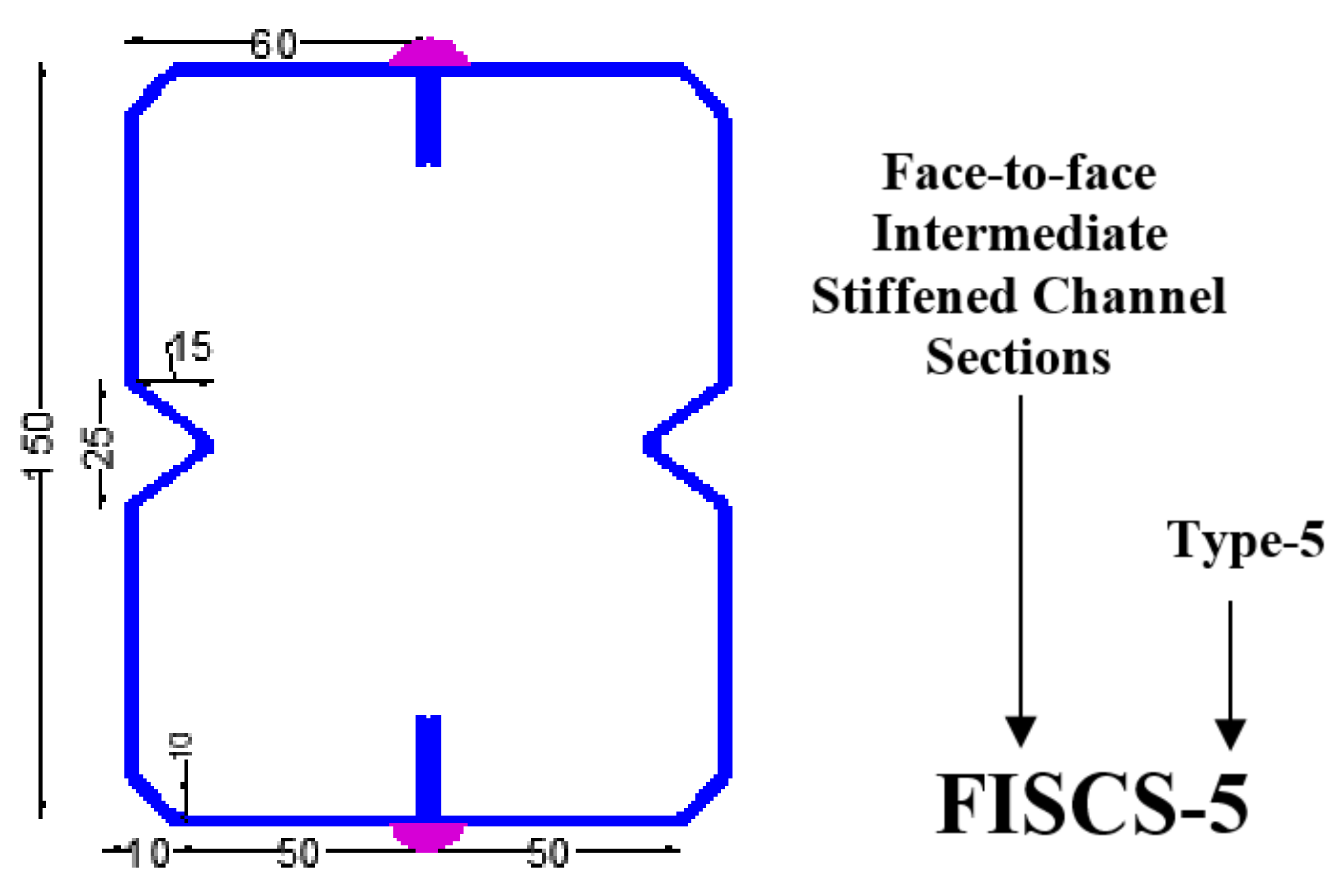
  • “Type-5” indicates lipped CFS channel columns with three stiffeners: (i) Intermediate web stiffeners (ii) Flange stiffeners and (iii) Lip stiffeners.
Figure 5. Specimen labelling for the experimental program.
Buildings 12 01071 g005

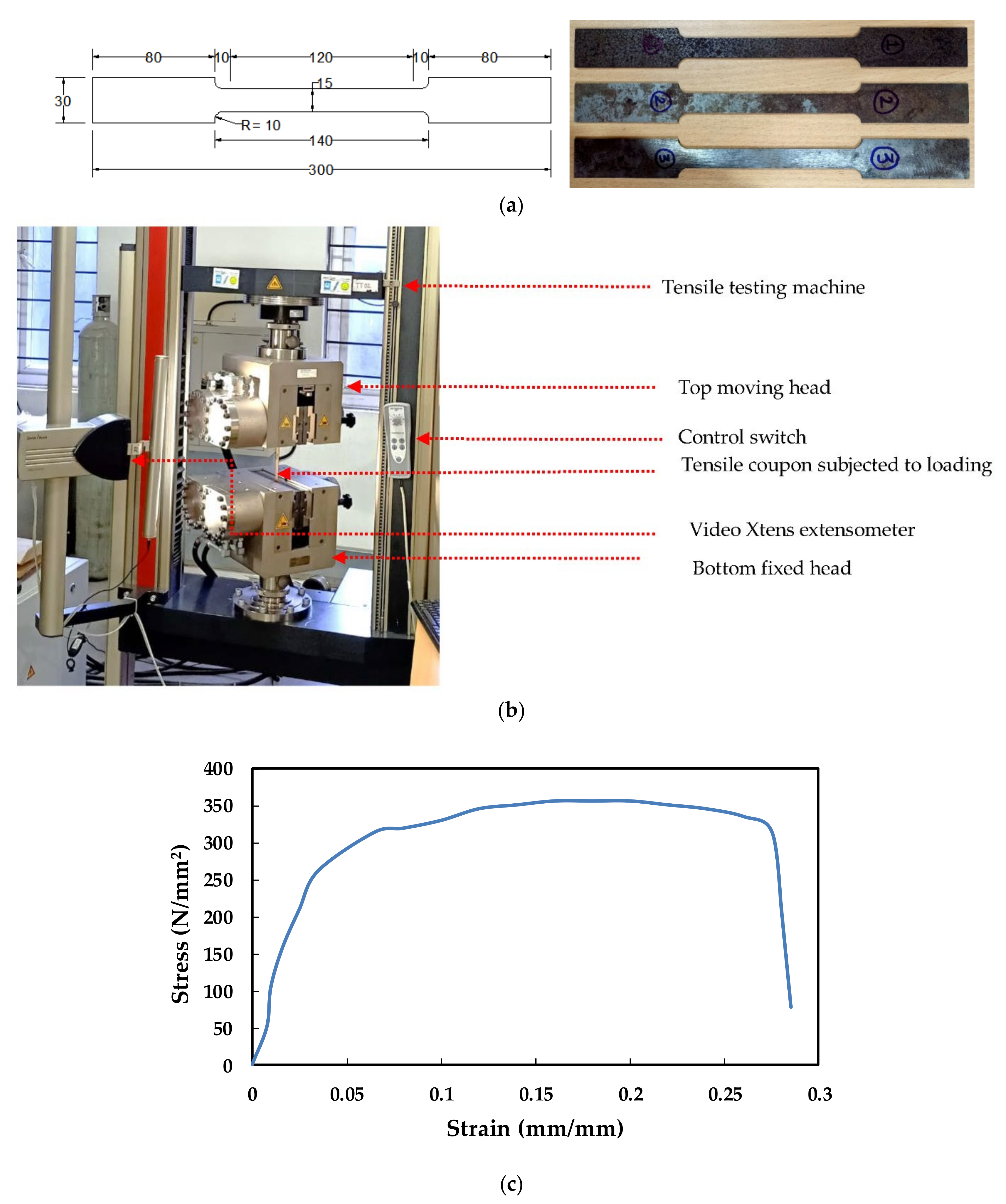
2.3. Material Testing

The flat portions were extracted from flange, web, and web-flange segments along their span. At least two coupons were cut and tested from each section group to determine the average results; thus, the error was minimised. This study did not take into account the effect of cold work forming at the corners. All tensile coupon specimens were prepared, sized, and tested in accordance with the EN ISO 6892-1-2009 [66] standard. A digital vernier calliper was used to take precise measurements of the cross-sections, length, width, and thickness. The width (b0 = 50 mm for sheet cut coupons and b0 = 30 mm for coupons cut from channels) was proportionate to the gripped end widths (b = 30 mm for sheet cut coupons and b = 15 mm for coupons cut from channels). The coupon sizes are illustrated in Figure 6a.
Tensile coupon tests were performed to determine the material properties of the test specimens. The procedures and suggestions of EN ISO 6892-1-2009 [66] were followed for the preparation and testing of the coupons. The tests were carried out with the help of a Zwick/RoellZ100 kN Electro-mechanical testing machine. Figure 6b depicts the tensile test setup for testing the coupons. The longitudinal strain was measured over a specified gauge length using a non-contact extensometer equipped with video-xtens technology. The flat coupons were gripped with a pair of flat surface grips. The coupons were subjected to a 0.01 mm/s crosshead movement. Figure 6c shows the stress-strain curve from the results of tensile coupon tests. The average Young’s modulus and yield strengths are 205 GPa and 266.30 MPa, respectively, as shown in Table 1. The average ratio of ultimate strength to yield stress, fu/fy = 1.35, which is greater than the 1.10 recommended by EN ISO 6892-1-2009 [66]. The mean value of fu/fy = 1.35 indicates that these cold-rolled sheets have good ductility. During the testing of coupons that exhibit high ductility behaviour, a large elongation and necking were observed prior to failure.

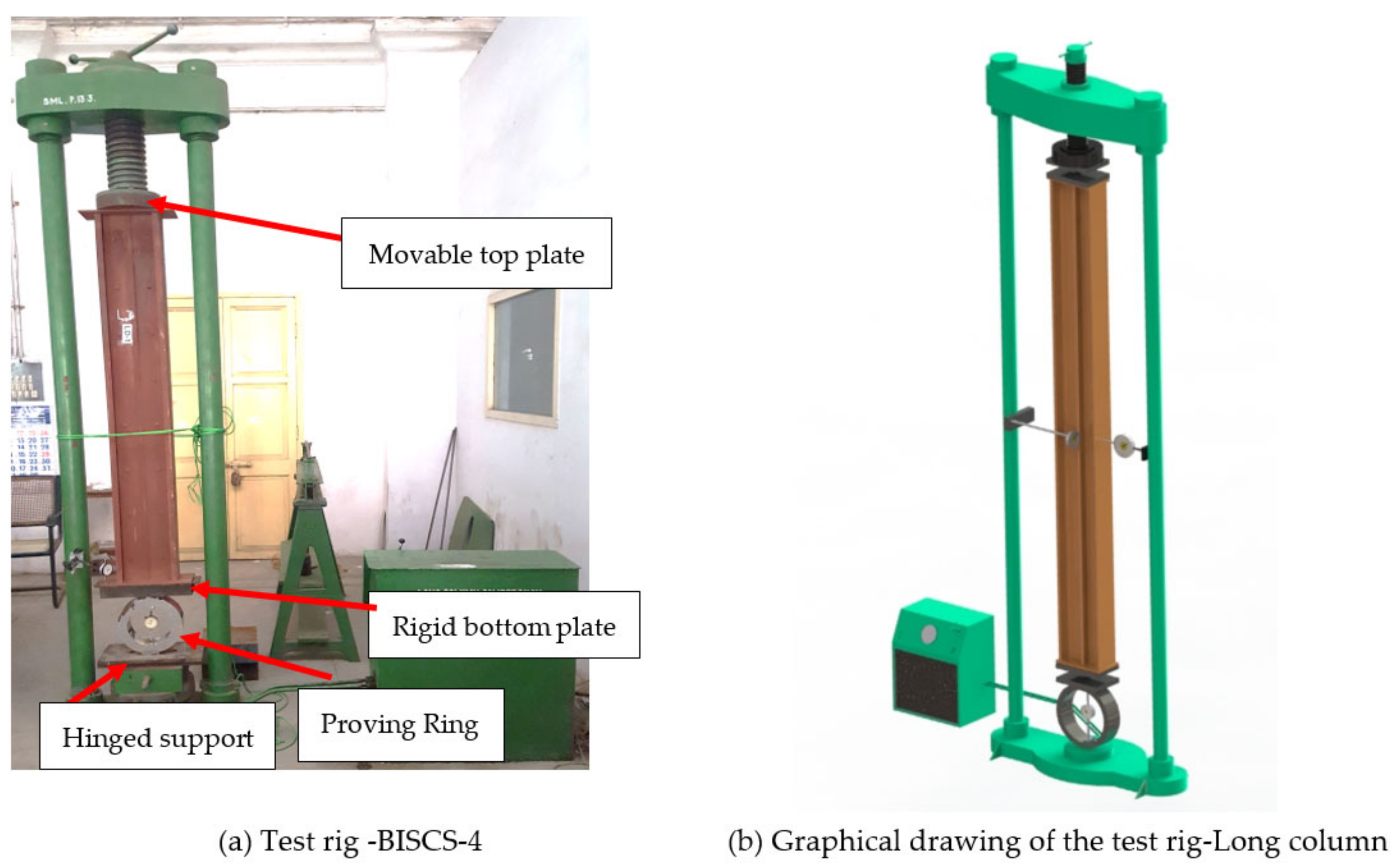
2.4. Loading and Testing Rig

Figure 7a,b show photographs of the single and built-up sections, respectively. Figure 8a,b show the sections positioned in the 250 kN loading frame before testing and the graphical drawing, respectively. Before testing, a small preload was applied. Under axial compression, ten new single (ISSCS) and back-to-back (BISCS) channel section columns with the top end of the column fixed and the bottom end with a translational degree of freedom along the vertical axis alone was tested. The ends of the test specimens were welded with two 16 mm thick end plates (250 mm × 250 mm). The top base plate was machined to have a smooth surface and welded so that the center of gravity of the top base plate matched the loading point. The axial and lateral displacements of all test specimens were measured using Mitutoyo and Batty dial gauges, with the least count of 0.01 mm. The concentric load was applied using the displacement control method. All test specimens were loaded at the same rate of 0.35 mm/min. After each increment of loading, the dial gauges and load cell readings were recorded. The specimens were loaded to their maximum capacity, after which there was a rapid increase in dial gauge readings but no increase in axial load. Until the specimen failed, the axial force was applied at a faster rate in the elastic range and a slower rate in the plastic range.

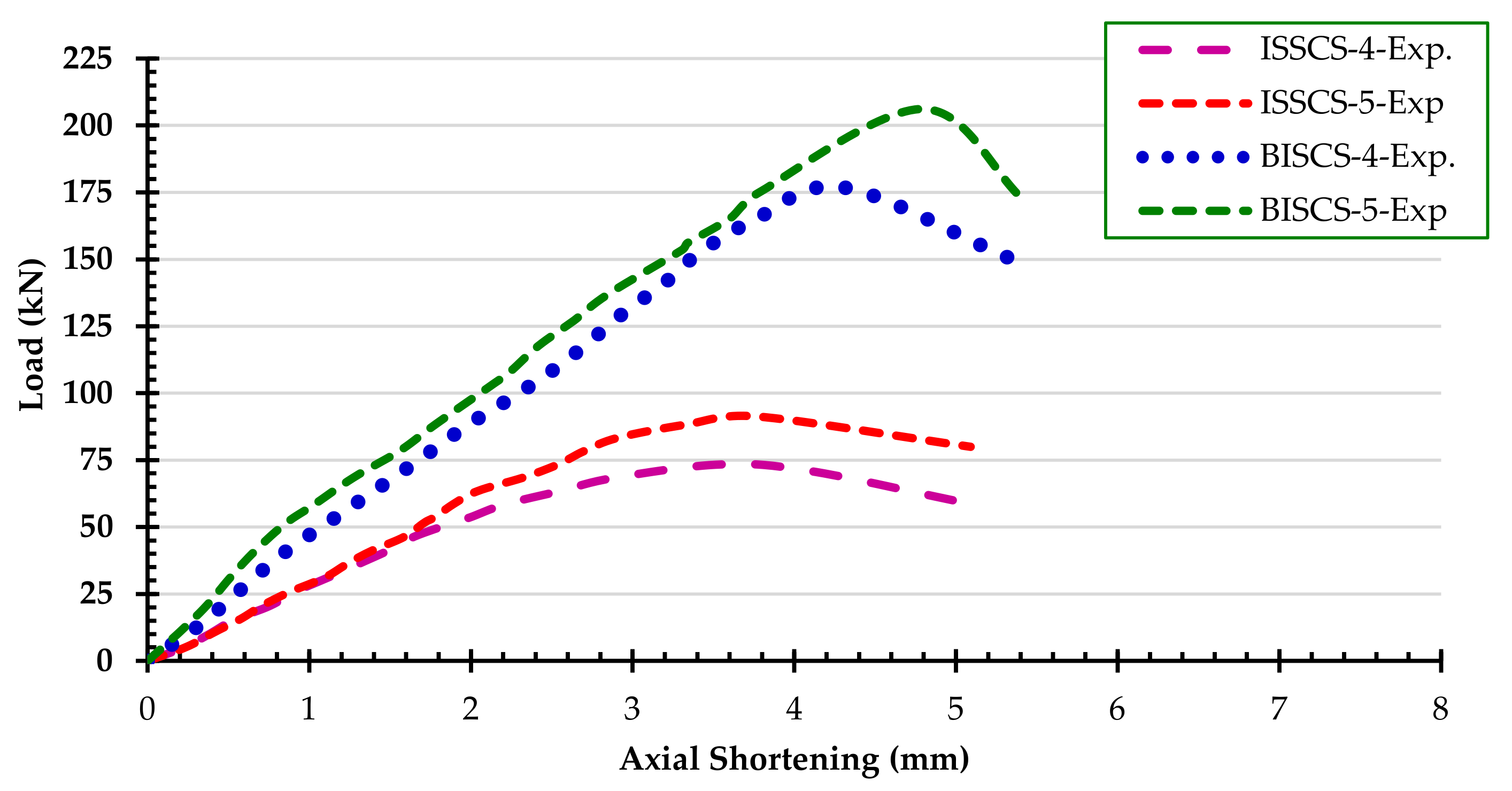
2.5. Experimental Results

Table 2 shows the experimental (PExp) strengths for 1.6 mm thick ISSCS and BISCS. As can be seen, the lip stiffened channel sections (ISSCS-5 and BISCS-5) with an intermediate web stiffener and stiffener at the junction of flange and web resulted in a higher failure load when compared with the other four specimens. Stiffeners only at the junction of flange and web do not have a significant influence on the axial capacity. The behaviour of both ISSCS and BISCS showed a 20% significant increase on an average significant increase in axial load by adding stiffeners at the junction of the flange and the web in addition to the web stiffener for the cases of both plain and lipped channel sections. The inclusion of stiffeners only in the web or along the junction of the web and the flange does not result in an improved axial load carrying capacity when compared with an unstiffened plain or lipped channel section. The addition of the multiple stiffeners (BISCS-5) improved the strength of built-up sections by 85% when compared with the plain built-up section (BISCS-1). These multiple intermediate stiffeners (BISCS-5) reduce the plate slenderness of the angles, thus increasing their compression resistance. The provision of stiffeners only at the junction of the flanges and web (i.e., BISCS-4) contributed only 17% of the extra strength compared with BISCS-5 but was shown to support the in-plane deflection of the shorter legs towards the major axis. The built-up channel sections failed due to an interaction of local and global buckling. Intermediate and global stiffeners are used to help prevent in-plane and out-of-plane buckling, increasing the load-carrying capacity of the members. Figure 9 Shows the typical load versus axial shortening curves of type 4 and type-5 ISSCS and BISCS sections.

3. Numerical Investigation

3.1. General

The finite element programme ABAQUS [67] was used. The FE models were created using the cross-section centre-line dimensions. Two types of finite element analyses were performed. The buckling modes of the ISSCS, BISCS, and FISCS columns were first determined using an eigenvalue analysis, a linear-elastic analysis performed with the ABAQUS library’s (*BUCKLE) procedure. The Riks algorithm from the ABAQUS library was then used to perform a load-displacement nonlinear analysis. The FE models incorporated the initial geometric imperfections and material nonlinearities. The following sections describe specific modelling techniques.

3.2. Material and Geometrical Properties

The full geometry of the ISSCS, BISCS, and FISCS parts was modelled. To account for material non-linearities, true values of stresses and strains are specified in the FE models. Material non-linearity was integrated into the finite element software by including true values of stresses and strains as determined during the coupon testing. A simplified elastic, perfectly plastic stress-strain curve following the von Mises yield criterion was used for the parametric study. As per the ABAQUS manual [67], the engineering material curve was converted into a true material curve by using the following equations:
σ t r u e = σ ( 1 + ε )
ε t r u e ( p l ) = ln ( 1 + ε ) σ t r u e E
where E is the Young’s Modulus, σ and ε are the engineering stress and strain, respectively, and σ t r u e and ε t r u e are the true stress and strain, respectively.

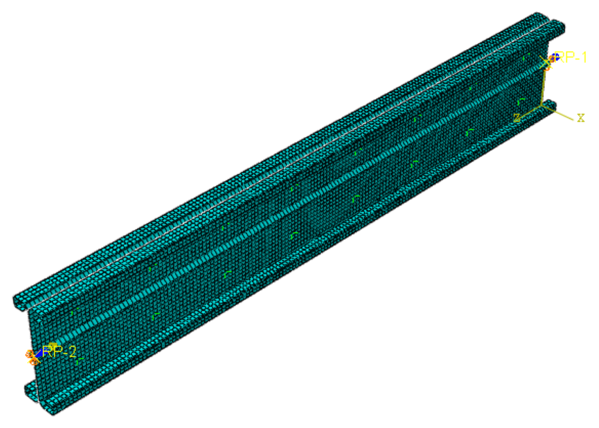
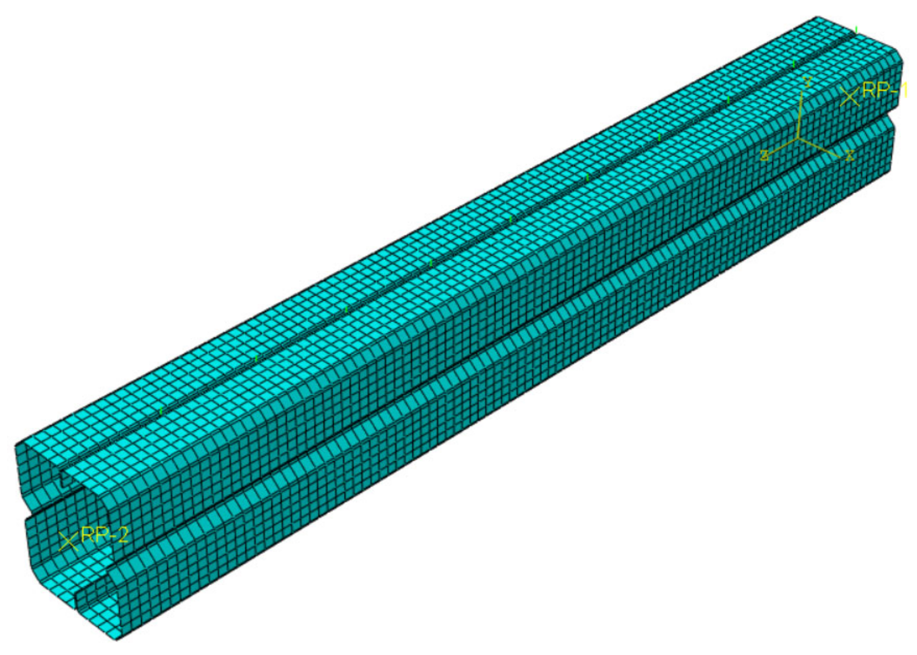
3.3. Type of Element, Mesh Size and Material

All the CFS channel sections were modelled using a linear 4-noded quadrilateral thick shell element (S4R5) from the ABAQUS element library. The models were converged using a mesh size of 10 mm × 10 mm (length × width). The typical FE meshes for BISCS-5 and FISCS-8 are shown in Figure 10 and Figure 11, respectively. For the experimental studies, the positioning of screws is shown in Figure 12.
In the parametric model, the weld connection between the chords model is simplified by using the edge-to-edge independent fastener with the weld option available in the ABAQUS [67], as shown in Figure 13. The residual stress induced by welding is ignored near the weld region since the weld was provided for a very shorter length in between the moment spans. Contact modelling and a small sliding formulation were implemented to simulate the interaction between the surfaces in the model. Contact analysis was done to prevent the penetration of layers during analysis. In the interaction property, surface-to-surface contact was defined as frictionless contact in tangential behaviour, and hard contact in normal behaviour was adopted by Ananthi et al. [3].

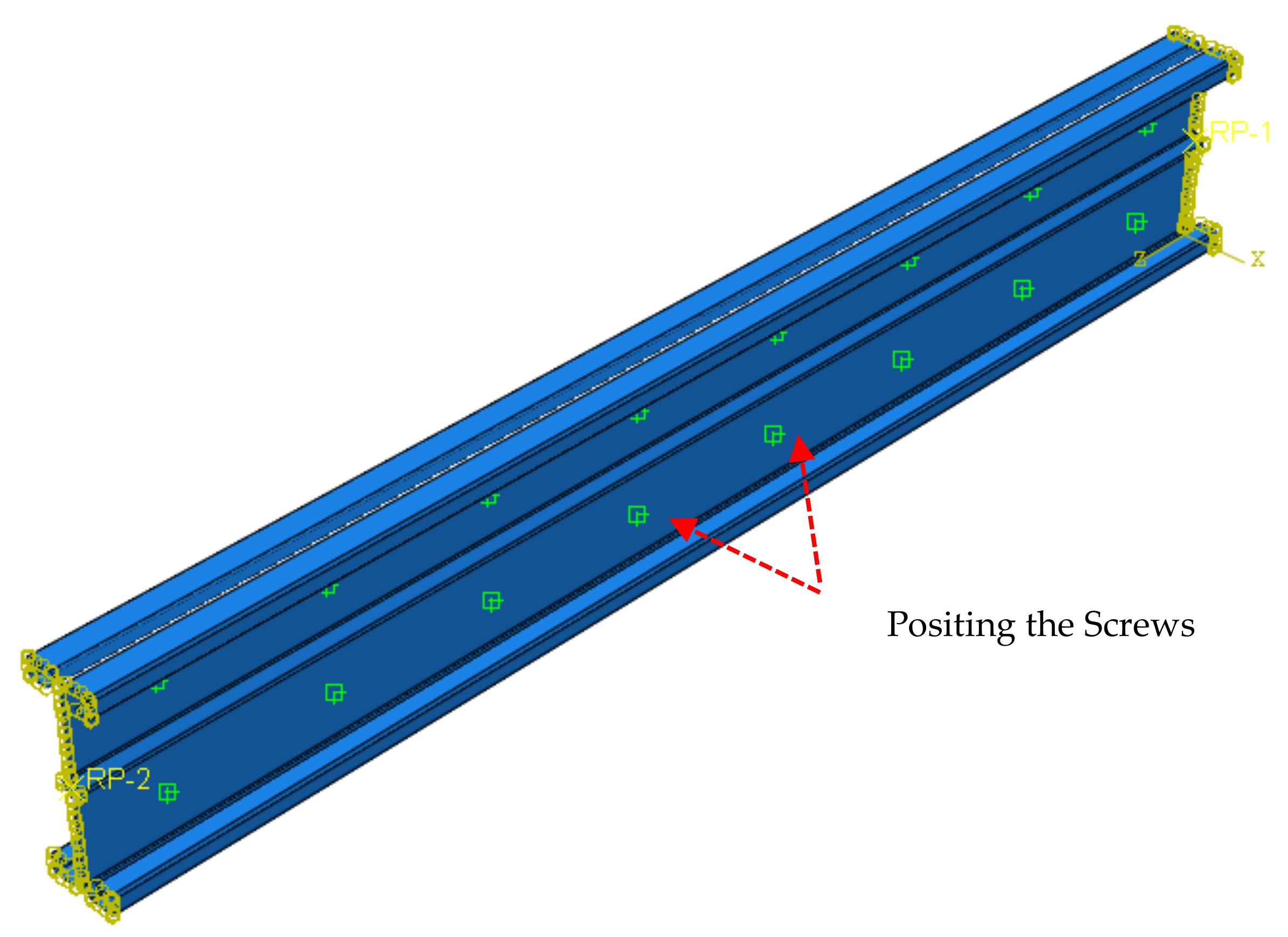
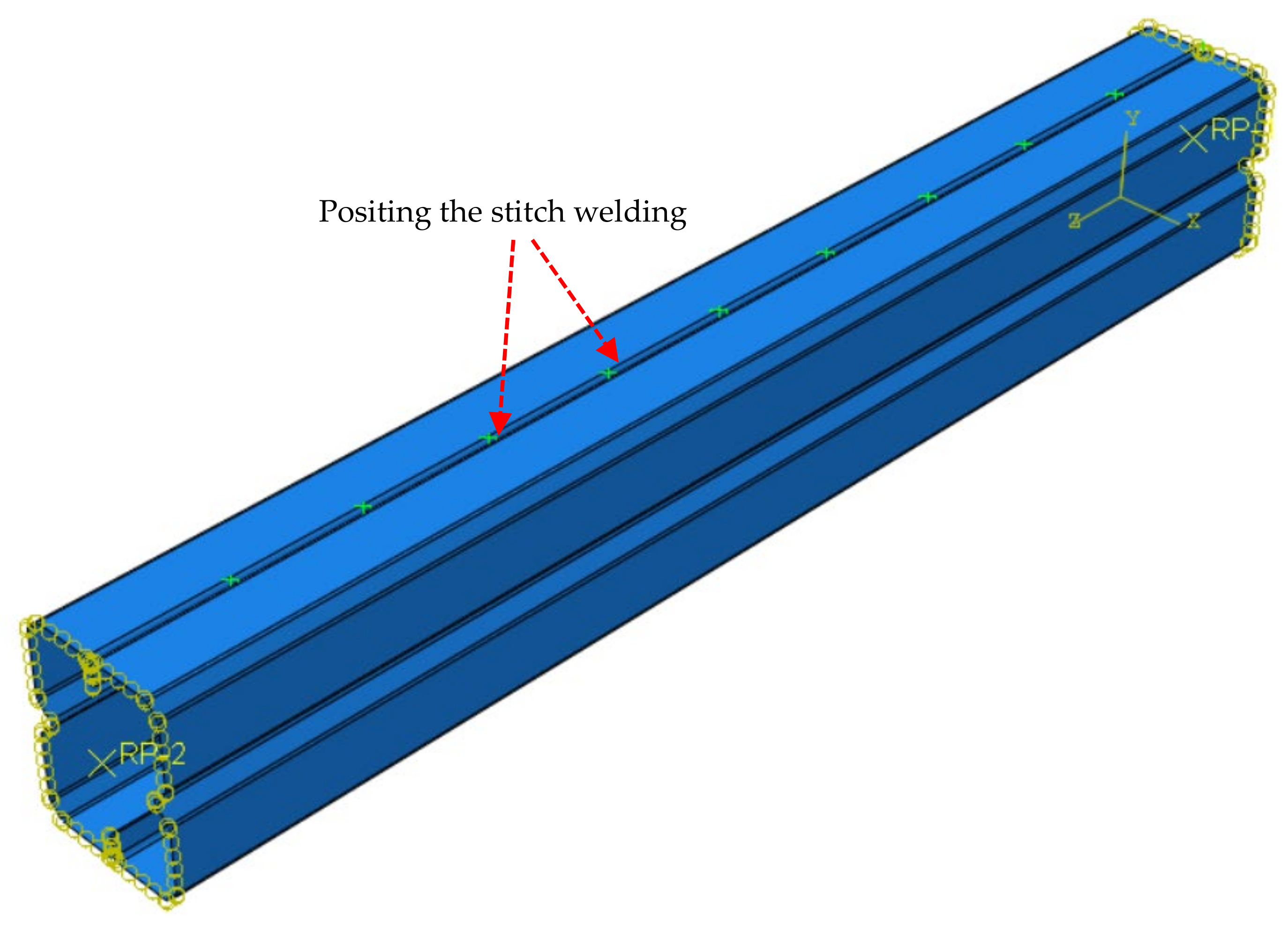
3.4. Load Application and Applied Boundary Conditions

The boundary conditions used for ISSCS and BISCS columns were with one end fixed and the other end with a translational degree of freedom along the vertical axis, whereas the FISCS columns were analysed numerically with both ends fixed. The reference point (RP-2) was considered as the centre of gravity (CG) of the cross-section through which the load was applied. The load is applied incrementally using an adjusted RIKS approach adopted from the ABAQUS library after considering the top end plate’s reference point. Figure 12 shows the MPC beam connector used to rigidly connect the column ends with the screws used in the experimental study. Figure 13 shows how the edge-to-edge mesh independent fastener with the weld option in ABAQUS [67] simplifies the weld connection between the chord models for the parametric study.

3.5. Material and Geometric Imperfection Modeling

As mentioned previously, the full geometry of the ISSCS, BISCS, and FISCS sections was modelled. True values of stresses and strains are specified in the FE models to incorporate the material non-linearities. The ABAQUS classical metal plasticity model was used for analysis and validation purposes. Isotropic yielding, associated plastic flow theory, and isotropic hardening behaviour are considered. According to Schafer and Pekoz [68], the magnitude of local, distortional, and global imperfections was assumed to be 0.006 × w × t, 1.0 × t, and 1/1000 of the column length. Figure 14 shows the local and distortional buckling modes for FISCS-1 and FISCS-3 determined from the FEA, respectively.

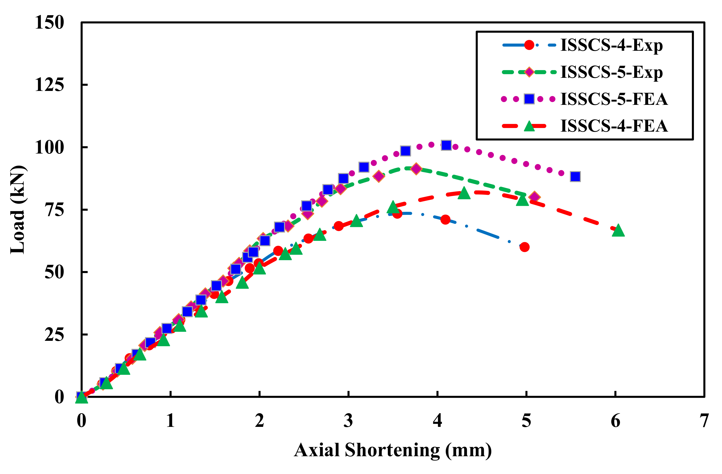
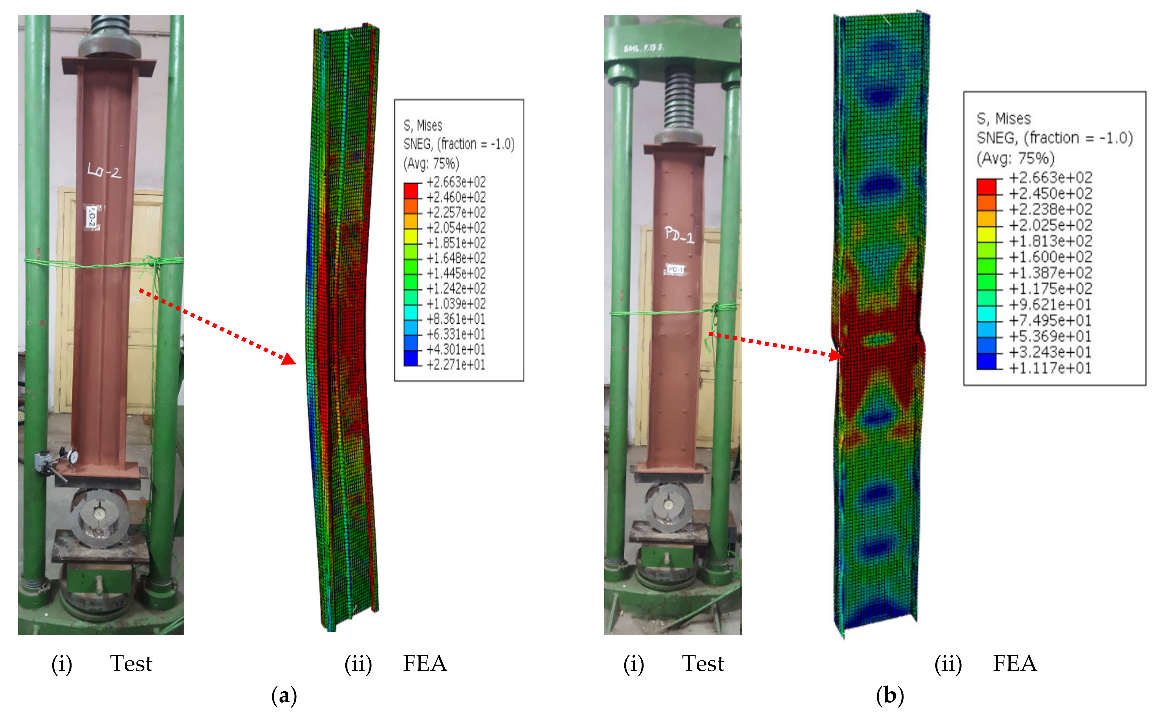
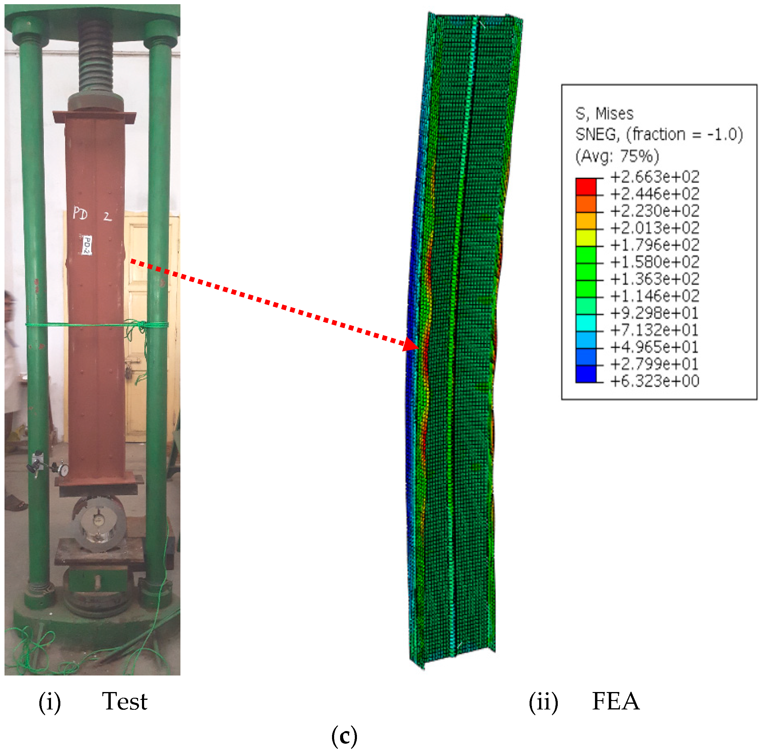
3.6. Justification of the FE Model

The variation of axial load against end shortening of ISSCS-4 and ISSCS-5 is shown in Figure 15. Generally, the load versus axial shortening behaviour was linear, up to 85% of the ultimate load. Throughout the post-buckling range, the data showed a modest increase in load, followed by an increase in end shortening. Nonlinear behaviour was exhibited in all the built-up back-to-back and face-to-face sections in the post-buckling area when the end-shortening rose beyond the critical buckling stress. The failure modes of the three specimens that are tested: ISSCS-5, BISCS-3, and BISCS-5 are depicted in Figure 16. As can be seen from Figure 15, the test and FE results are in good agreement up to the yield limit, and the test curve drops at a much faster rate compared to the FE results. Furthermore, in terms of failure modes, the experimental buckling modes closely matched the FEA buckling modes, as shown in Figure 16. Table 2 compares the experimental failure loads with the FE analysis failure loads for the ISSCS and BISCS. For ISSCS and BISCS, the ratio of PEXP/PDSM is 0.96, and PEXP/PFEA is 0.93, on average.

4. Design Guidelines in Accordance with AISI and AS/NZ Standards

The un-factored design strength of axially loaded compression members in single (ISSCS) and the built-up sections (BISCS and FISCS) were determined according to the AISI [35] and AS/NZS [36] is as follows:
P AISI & AS / NZS = A e F n
The critical buckling stress (Fn) can be calculated using Equations (4) and (5) as follows:
For   λ c 1.5 ,   F n = 0.658 λ 2 F y
For   λ c > 1.5 ,   F n = 0.877 λ c 2 F y
The non-dimensional critical slenderness (λc) can be calculated using Equation (6) as given below:
λ c = F y F e
According to AISI [35] and AS/NZS [36], the modified slenderness ratio can be calculated as per Equation (7):
KL r m = KL r 0 2 + S r i 2   When ,   S r i   0.5   KL r o
P DSM = min P ne , P nl , P nd
The nominal axial strength (Pne) for flexural buckling can be calculated using Equation (9).
P ne = 0.658 λ 2 c P y     for   λ c   1.5 0.877 λ 2 c P y   for   λ c > 1.5
where, λ c = P y P cre and P y = Af y
P nl = P ne   for   λ l 0.776 1 0.15   P crl P ne 0.4 P crl P ne 0.4 P ne     for   λ l > 0.776
where λ l = P ne P crl and, P crl = Af ol .
The nominal axial strength (   P nd   ) for distortional buckling can be calculated using Equation (11) as given below:
  P nd   = P y   for   λ d 0.561 1 0.25   P crd P y 0.6 P crd P y 0.6 P y   for   λ d > 0.561
where, λ d = P y P crd and, P crd = Af od .

5. Analysis of Design Strengths
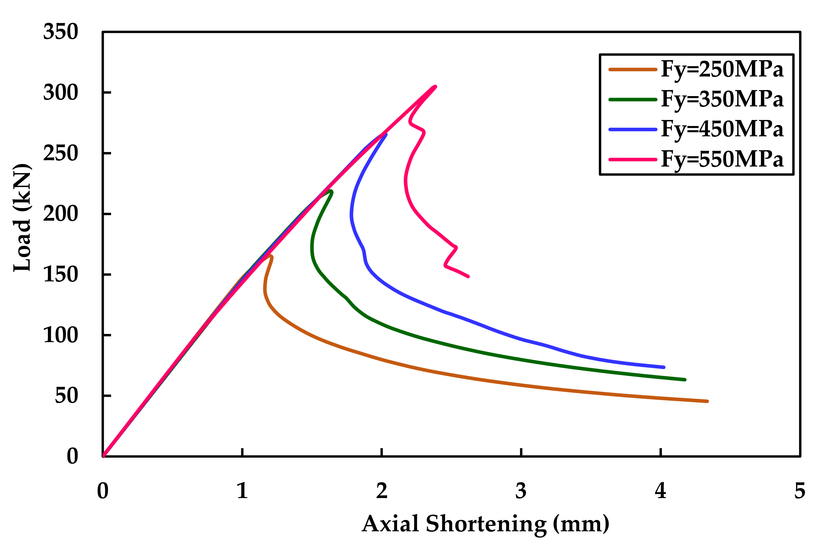
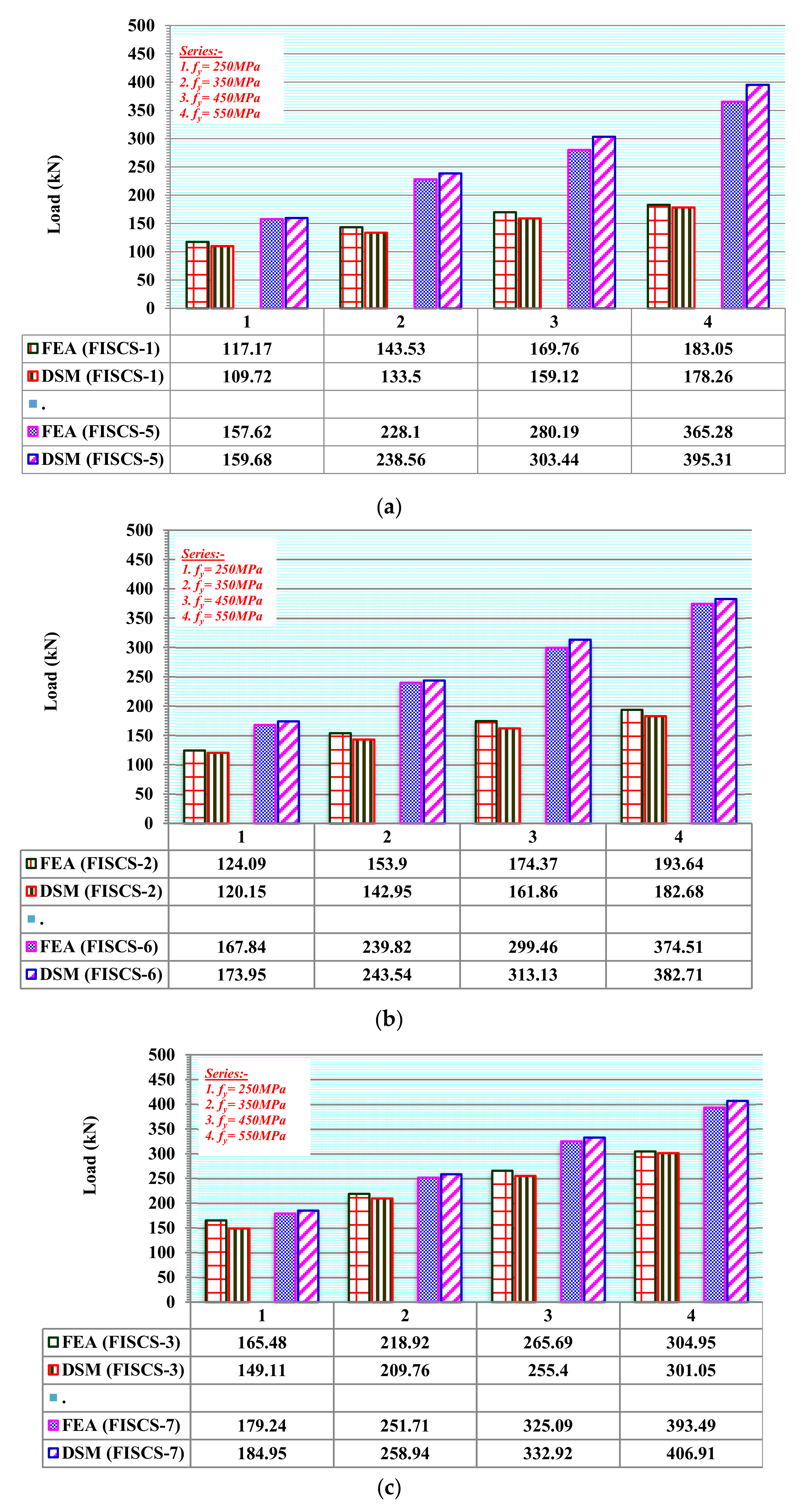
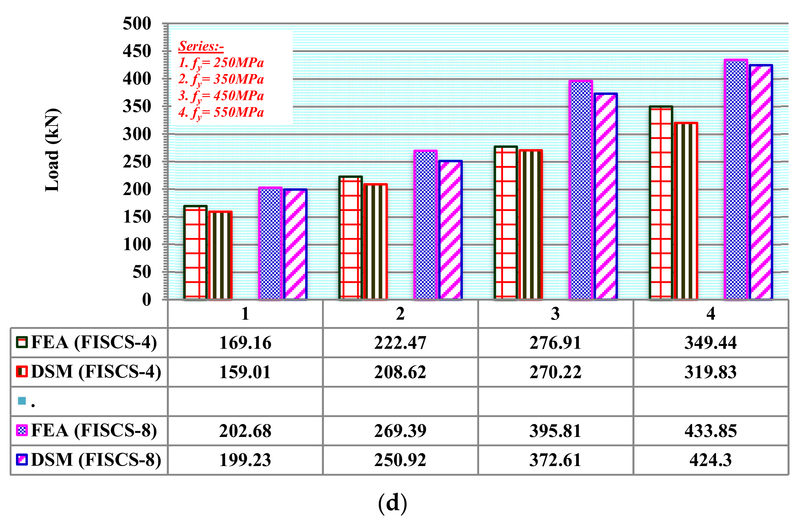
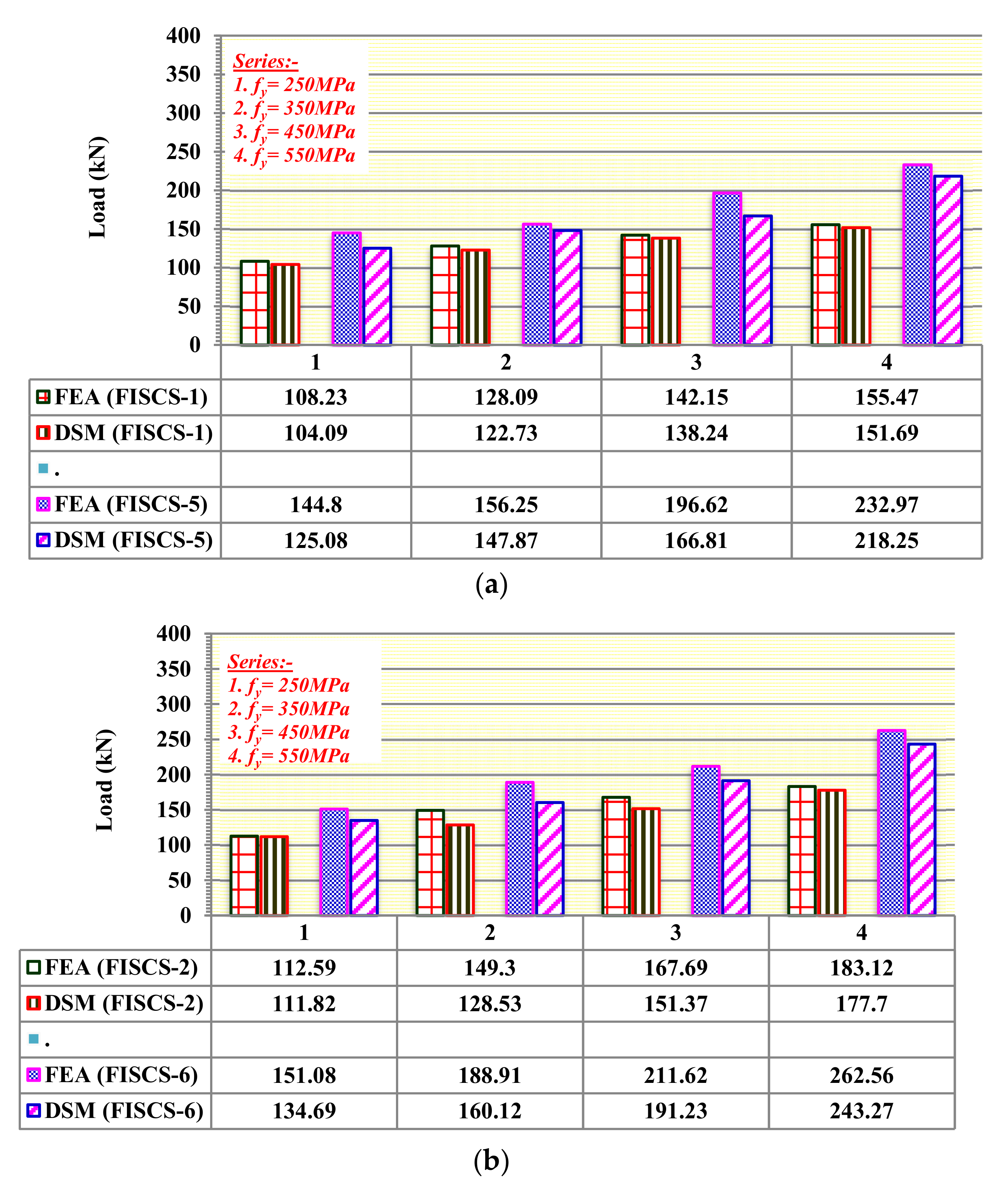
For the ISSCS and BISCS, Table 2 compares the FEA strengths and the design strengths estimated according to AISI [35] and AS/NZS [36]. The FEA predictions for plain ISSCS channels are up to 24% higher when compared to the design strengths. With exceptions for BISCS-1, BISCS-4, and BISCS-5 specimens, where predictions marginally underestimate the experimental behaviour, the FEA over predicted the ultimate loads of the DSM by up to 18%. Plate buckling occurred at the mid-height of both the plain and lipped ISSCS. BISCS-5 had a failure pattern like ISSCS-5 in the midsection, but plate buckling was more common in the lip region. The behaviour of both ISSCS and BISCS when stiffeners are positioned at the flange-web intersection did not demonstrate an increase in strength.

6. Parametric Study

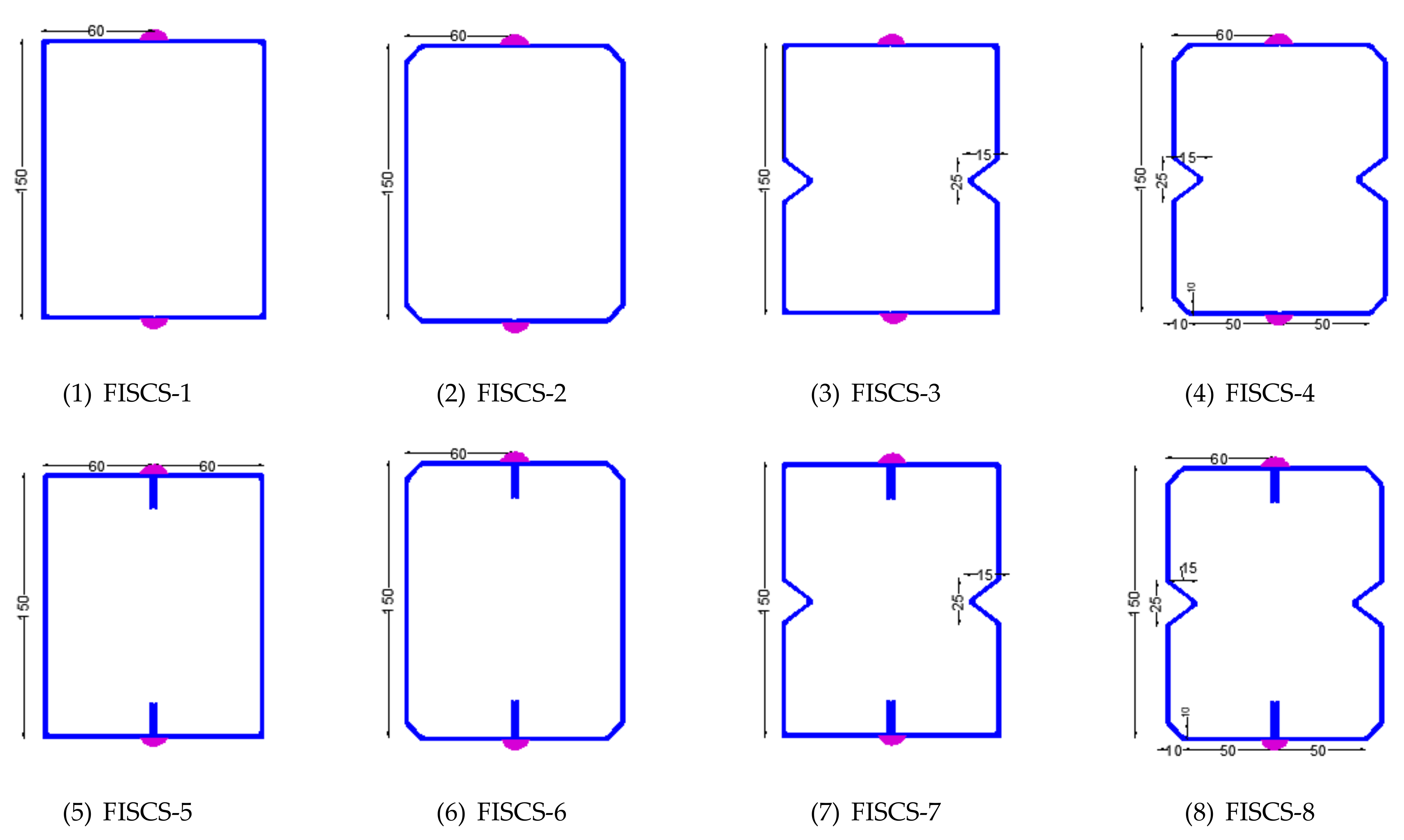
Sections Labelling for Parametric Studies

The specimen labelling for the parametric study is shown in Figure 17. It explains the type of section, section geometry, and stiffeners.
  • “Type-1 and Type-5” indicate CFS channel columns with no stiffeners for plain and lipped sections, respectively.
  • “Type-2 and Type-6” indicate CFS channel columns with only flange stiffeners for plain and lipped sections, respectively.
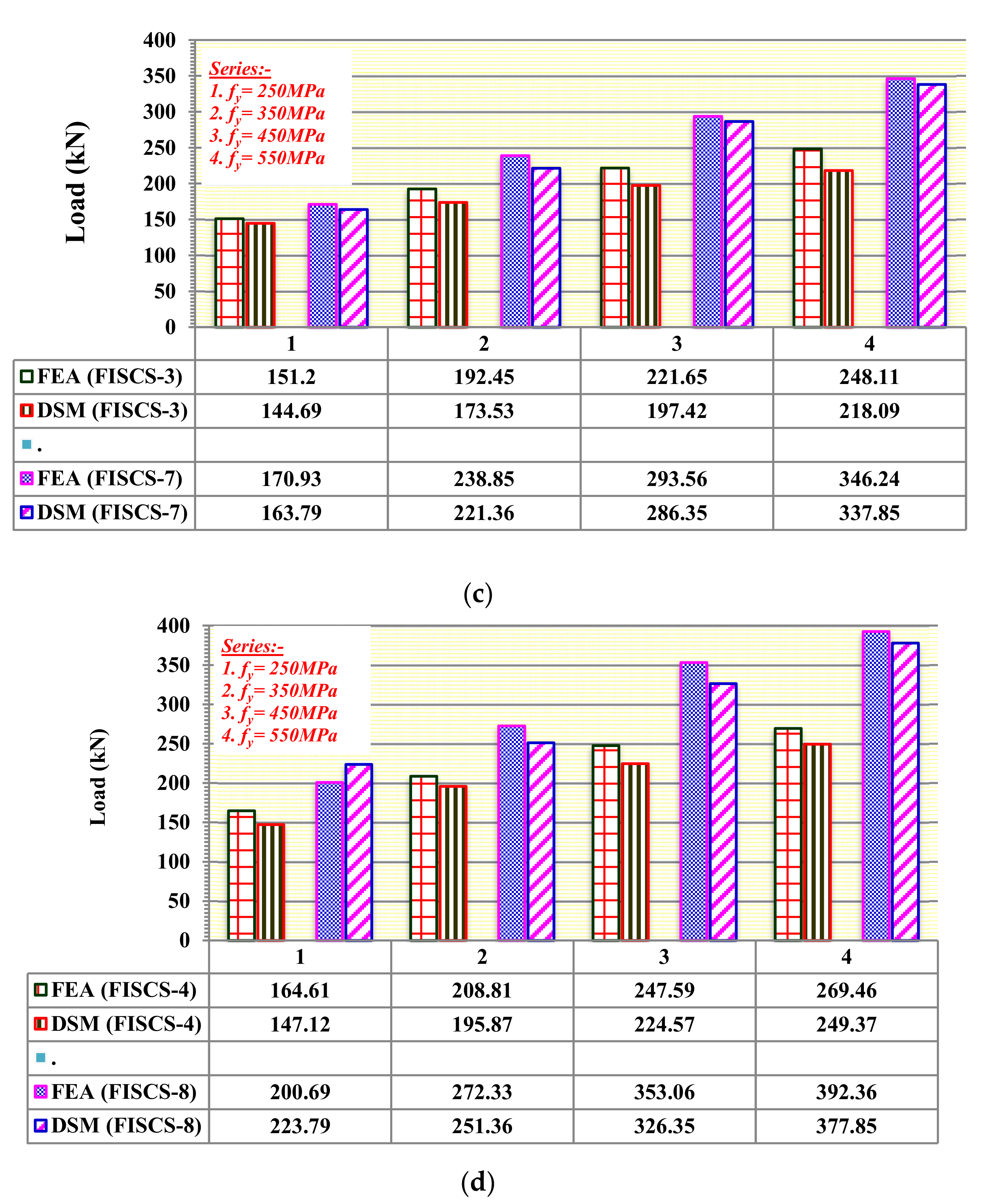
  • “Type-3 and Type-7” indicate CFS channel columns with only intermediate web stiffeners for plain and lipped sections, respectively.
  • “Type-4 and Type-8” indicate CFS channel columns with both intermediate web stiffeners and flange stiffeners for plain and lipped sections, respectively.
Figure 17. Specimen labelling for parametric studies.
Buildings 12 01071 g017
Figure 18 shows the different geometrical cross-sections considered in this study. Eight CFS built-up sections are considered. Four different yield stresses are considered. In total, the parametric study comprised 64 models for Face-to-Face intermediate stiffened channel sections (FISCS), which are welded with intermittent stitch welding at 100 mm spacing. The specimen initially demonstrated elastic-plastic failure and ended with post-buckling failure, with the flanges deflecting outwards on both sides as the load approached the ultimate load.
All FISCS failed as a result of buckling of plates at the mid height of the columns. The load versus axial shortening behaviour for the FISCS-3 specimen is shown in Figure 19. Figure 19 shows the gradual increase in the axial load for the yield stresses between 250 MPa and 450 MPa. Whereas for yield stress of 550 MPa, after the ultimate strength was reached, the drop in the load was sudden, showing less ductility for a higher grade of steel. Figure 20 shows the deformed shapes obtained from the FEA for the specimen FISCS-3. The provision of stiffeners in between the flange and the web did not result in a significant increase in load when compared to adding stiffeners on the web. All column specimens from FISCS-1 to FISCS-6 failed due to local buckling, whereas FISCS-7 and FISCS-8 failed due to distortional buckling for a length of 1000 mm. FISCS-1 to FISCS-6 columns failed due to local buckling and through a combination of local and flexural buckling for lower and higher grades of steel, respectively. Whereas for FISCS-7 and FISCS-8, the failure mechanism was due to a combination of distortional and flexural buckling, irrespective of the grades of steel. Figure 21 and Figure 22 demonstrate the relationship between load and yield stresses for all face-to-face intermediate stiffened channel sections.

7. Conclusions

A study into the axial compressive behaviour of thin-walled steel Intermediate Stiffened Single Channel Sections (ISSCS) and Back-to-Back Intermediate Stiffened Channel Sections (BISCS) has been described. Based on the validated FEA models on single and back-to-back double-channel sections, a parametric study was conducted on Face-to-Face intermediate stiffened channel sections (FISCS). It was found that:
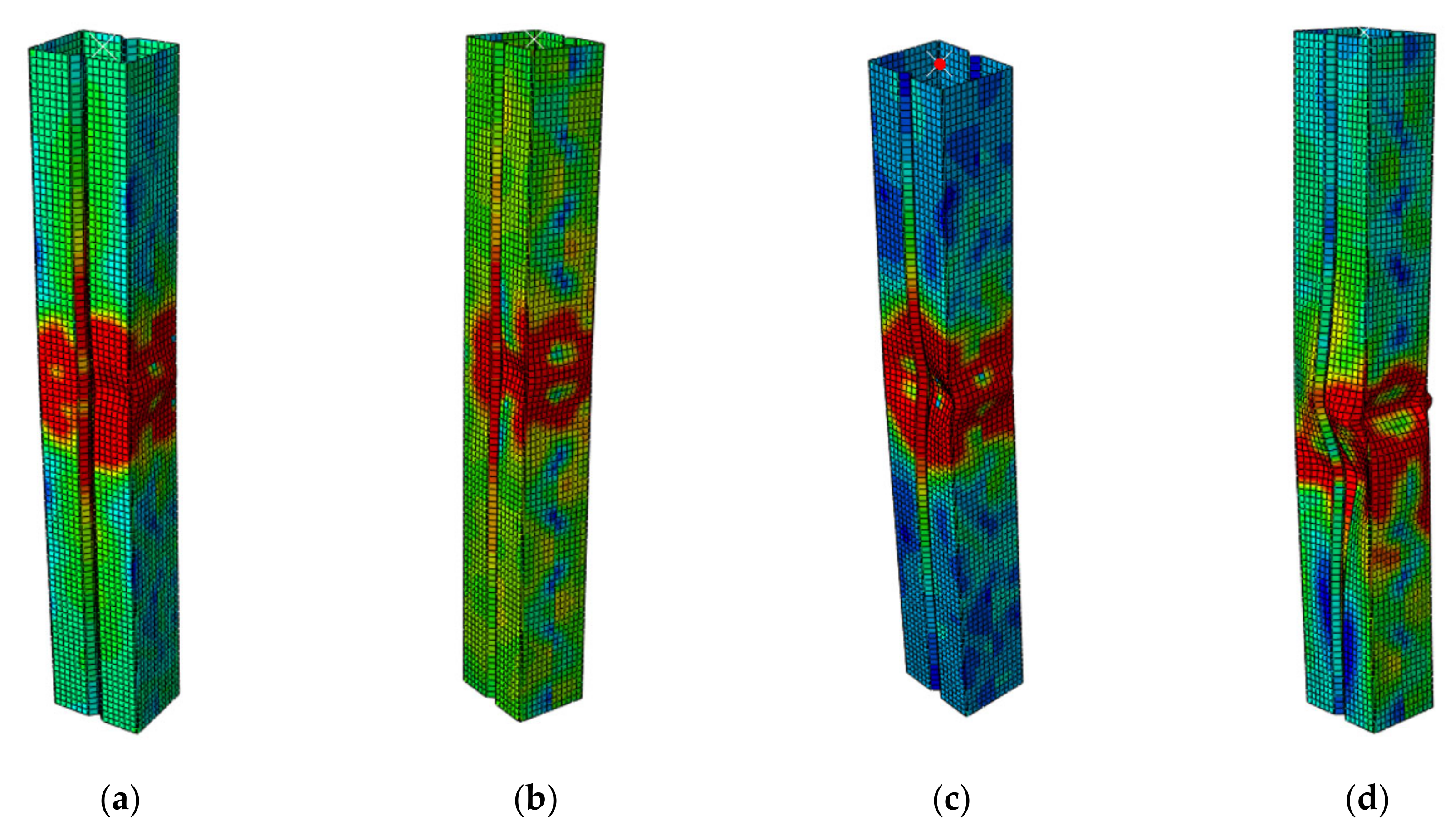
  • Single-channel sections failed due to local buckling, which initiated from the flanges towards the web, plus flexural buckling after the yielding limit was reached.
  • Plate buckling at the mid-height was observed in the doubly symmetric plain sections, which are fastened back-to-back.
  • Using web stiffeners in conjunction with flange stiffeners resulted in a high ultimate load-carrying capacity compared to other combinations.
  • Adding stiffeners to the flange-web connection does not result in a significant increase in load compared to using a web stiffener.
  • The prediction by the FEA overestimated the ultimate load by up to 7% on average, whereas the DSM predictions overestimated the results by up to 4% on average irrespective of the cross-sections.
  • The load-carrying capability of the portion with both the intermediate and flange stiffeners is not much higher than the other section in the ISSCS cross-sections.
  • The addition of stiffeners between the flange and the web did not result in a substantial increase in load compared to the performance of sections that included stiffeners to the web for sections both with and without lip geometry.
  • Plate buckling inside or outside of the web area resulted in built-up face-to-face columns as well.
The main limitation of this study is that, in the case of BISCS, the provision of stiffeners both on the mid-web and at the intersection of the flange and the web is difficult to fabricate for a lesser web depth. Also, to enhance the axial strength property of the BISCS sections, multiple stiffeners can be provided only on the web if the web depth is within the permissible limit as per the AISI [35] codal provision. In the case of FISCS, the stitch welding provided to connect the face-to-face plain sections is easier compared to the lipped sections due to the corner radius at the junction of the flange and the lip.
Further research is needed to improve the accuracy of design rules for such innovative CFS columns.

Author Contributions

Conceptualization, B.G.A.G. and K.R.; methodology, B.G.A.G. and K.R.; investigation, B.G.A.G., K.R., G.M.R., J.B.P.L.; writing—original draft preparation, B.G.A.G. and K.R. writing—review and editing, B.G.A.G., K.R., G.M.R., J.B.P.L. All authors have read and agreed to the published version of the manuscript.

Funding

This research received no external funding.

Institutional Review Board Statement

Not applicable.

Informed Consent Statement

Not applicable.

Data Availability Statement

Not applicable.

Conflicts of Interest

The authors declare no conflict of interest.

Notations

AGross area of the section;
AeEffective cross-sectional area;
AISIAmerican Iron and Steel Institute;
AS/NZSAustralian and New Zealand Standards;
CFSCold-formed steel;
COVCoefficient of variation;
A’Overall web length of section;
AeEffective area of the section;
B’Overall flange width of section;
C’Overall lip width of section;
DSMDirect Strength Method;
EModulus of elasticity;
FyYield strength;
FuUltimate tensile strength of steel;
FnNominal compressive stress;
FEMFinite element modelling;
fodDistortional buckling stress;
folElastic local buckling stress;
fyYield stress;
KEffective length factor;
LUnbraced member length;
LoGauge Length;
PcreCritical elastic flexural buckling load;
PFEAAxial strength from experiments;
PEXPAxial strength from the finite element analysis;
PDSMAxial strength calculated by Direct Strength Method;
PAISI/AS&NZSAxial design strength in accordance with AISI (2016) & AS/NZS (2018);
PneNominal axial strength for flexural buckling;
PndNominal axial strength for distortional buckling;
PnlNominal axial strength for local buckling;
SScrew spacing;
tThickness;
σ 0.2 Static 0.2% proof stress;
λSlenderness ratio;
λlSlenderness factor due to local buckling;
λdSlenderness factor due to distortional buckling;

References

  1. Ananthi, G.B.G.; Roy, K.; Lim, J.B.P. Experimental and numerical investigations on axial strength of back-to-back built-up cold-formed steel angle columns. Steel Compos. Struct. Int. J. 2019, 31, 601–615. [Google Scholar]
  2. Ananthi, G.B.G.; Roy, K.; Chen, B.; Lim, J.B.P. Testing, simulation and design of back-to-back built-up cold-formed steel unequal angle sections under axial compression. Steel Compos. Struct. Int. J. 2019, 33, 595–614. [Google Scholar]
  3. Ananthi, G.B.G.; Deepak, M.S.; Roy, K.; Lim, J.B.P. Influence of intermediate stiffeners on the axial capacity of cold-formed steel back-to-back built-up unequal angle sections. Structures 2021, 30, 477–494. [Google Scholar] [CrossRef]
  4. Ananthi, G.B.G.; Roy, K.; Lim, J.B.P. Behaviour and strength of back-to-back built-up cold-formed steel unequal angle sections with intermediate stiffeners under axial compression. Steel Compos. Struct. Int. J. 2022, 42, 1–22. [Google Scholar]
  5. Ananthi, G.B.G.; Roy, K.; Lim, J.B.P. Tests and finite element modelling of cold-formed steel zed and hat section columns under axial compression. Int. J. Steel Struct. 2021, 21, 1305–1331. [Google Scholar] [CrossRef]
  6. McIntosh, A.; Gatheeshgar, P.; Gunalan, S.; Kanthasamy, E.; Poologanathan, K.; Corradi, M.; Higgins, C. Unified approach for the web crippling design of cold-formed channels: Carbon steel, stainless steel and aluminium. J. Build. Eng. 2022, 51, 104134. [Google Scholar] [CrossRef]
  7. Adil Dar, M.; Dipti, R.; Sahoo, A.; Jain, K.; Verma, A. Tests on CFS Laced Columns Composed of Plain Channels: Behavior and Design. J. Struct. Eng. 2022, 148, 04022043. [Google Scholar]
  8. Rinchen, R.; Rasmussen, K. Experiments on Long-Span Cold-Formed Steel Single C-Section Portal Frames. J. Struct. Eng. 2020, 146, 4019187. [Google Scholar] [CrossRef]
  9. Blum, H.; Rasmussen, K. Experimental and numerical study of connection effects in long-span cold-formed steel double-channel portal frames. J. Constr. Steel Res. 2019, 155, 480–491. [Google Scholar] [CrossRef]
  10. Sivaganesh, S.; Mahendrakumar, M. Design of Cold-formed Steel Built-Up Closed Section Columns using Direct Strength Method. Thin-Walled Struct. 2022, 171, 108746. [Google Scholar]
  11. Janarthanan, B.; Gunalan, S.; Mahendran, M. Numerical modelling of web crippling failures in cold-formed steel unlipped channel sections. J. Constr. Steel Res. 2019, 158, 486–501. [Google Scholar] [CrossRef]
  12. Gunalan, S.; Mahendran, M. Experimental study of unlipped channel beams subject to web crippling under one flange load cases. Adv. Steel Constr. 2019, 15, 165–172. [Google Scholar]
  13. Chandramohan, D.L.; Kanthasamy, E.; Gatheeshgar, P.; Poologanathan, K.; Fareedh, M.; Ishqy, M.; Suntharalingam, T.; Kajaharan, T. Shear behaviour and design of doubly symmetric hollow flange beam with web openings. J. Constr. Steel Res. 2021, 185, 106836. [Google Scholar] [CrossRef]
  14. Fang, Z.; Roy, K.; Chandramohan, D.; Pranomrum, P.; Li, F.; Lau, H.; Lim, J.B.P. Structural behaviour of back-to-back cold-formed steel channel sections with web openings under axial compression at elevated temperatures. J. Build. Eng. 2022, 54, 104512. [Google Scholar] [CrossRef]
  15. Chen, B.; Roy, K.; Fang, Z.; Uzzaman, A.; Pham, C.H.; Raftery, G.; Lim, J.B.P. Shear behavior and design cold-formed steel channels with edge-stiffened hole, un-stiffened hole, and plain web. J. Struct. Eng. 2022, 148, 4021268. [Google Scholar] [CrossRef]
  16. Degtyareva, N.; Gatheeshgar, P.; Poologanathan, K.; Gunalan, S.; Shyha, I.; McIntosh, A. Local buckling strength and design of cold-formed steel beams with slotted perforations. Thin-Walled Struct. 2020, 156, 106951. [Google Scholar] [CrossRef]
  17. Craveiro, H.D.; Rodrigues, J.P.C.; Laim, L. Experimental analysis of built-up closed cold-formed steel columns with restrained thermal elongation under fire conditions. Thin-Walled Struct. 2016, 107, 564–579. [Google Scholar] [CrossRef]
  18. Nie, S.F.; Zhou, T.; Eatherton, M.R.; Li, J.; Zhang, Y. Compressive behaviour of built-up double-box columns consisting of four cold-formed steel channels. Eng. Struct. 2020, 222, 111–133. [Google Scholar] [CrossRef]
  19. Anbarasu, M. Numerical investigation on behaviour and design of cold-formed steel built-up column composed of lipped sigma channels. Adv. Struct. Eng. 2019, 22, 1817–1829. [Google Scholar] [CrossRef]
  20. Zhou, X.; Xiang, Y.; Shi, Y.; Xu, L.; Zou, Y. Simplified design method of cold-formed steel columns with built-up box sections. Eng. Struct. 2020, 228, 111532. [Google Scholar] [CrossRef]
  21. Roy, K.; Ting, T.C.H.; Lau, H.H.; Lim, J.B.P. Experimental and numerical investigations on the axial capacity of cold-formed steel built-up box sections. J. Constr. Steel Res. 2019, 160, 411–427. [Google Scholar] [CrossRef]
  22. Roy, K.; Mohammadjani, C.; Lim, J.B.P. Experimental and numerical investigation into the behaviour of face-to-face built-up cold-formed steel channel sections under compression. Thin-Walled Struct. 2019, 134, 291–309. [Google Scholar] [CrossRef]
  23. Ananthi, G.B.G.; Ashvini, B. Experimental theoretical and numerical studies on cold-formed steel stub channel columns with stiffeners. Asian J. Civ. Eng. 2019, 20, 171–185. [Google Scholar] [CrossRef]
  24. Roy, K.; Ting, T.C.H.; Lau, H.H.; Lim, J.B.P. Nonlinear behaviour of back-to-back gapped built-up cold-formed steel channel sections under compression. J. Constr. Steel Res. 2018, 147, 257–276. [Google Scholar] [CrossRef]
  25. Roy, K.; Ting, T.C.H.; Lau, H.H.; Lim, J.B.P. Nonlinear behavior of axially loaded back-to-back built-up cold-formed steel un-lipped channel sections. Steel Compos. Struct. Int. J. 2018, 28, 233–250. [Google Scholar]
  26. Zhang, J.H.; Young, B. Numerical investigation and design of cold-formed steel built-up open section columns with longitudinal stiffeners. Thin-Walled Struct. 2015, 89, 178–191. [Google Scholar] [CrossRef]
  27. Zhang, J.H.; Young, B. Experimental investigation of cold-formed steel built-up closed section columns with web stiffeners. J. Constr. Steel Res. 2018, 147, 380–392. [Google Scholar] [CrossRef]
  28. Zhang, J.H.; Young, B. Finite element analysis and design of cold-formed steel built-up closed section columns with web stiffeners. Thin-Walled Struct. 2018, 131, 223–237. [Google Scholar] [CrossRef]
  29. Ananthi, G.B.G.; Palani, G.S.; Iyer, N.R. A study on cold-formed steel web stiffened lipped battened channel columns. J. Struct. Eng. (JoSE) 2016, 4, 133–141. [Google Scholar]
  30. Li, Y.Q.; Li, Y.L.; Wang, S.K.; Shen, Z.Y. Ultimate load-carrying capacity of cold-formed thin-walled columns with built-up box and I section under axial compression. Thin-Walled Struct. 2014, 79, 202–217. [Google Scholar] [CrossRef]
  31. Phan, D.K.; Rasmussen, K.J.R.; Schafer, B.W. Tests and design of built-up section columns. J. Constr. Steel Res. 2021, 181, 106619. [Google Scholar] [CrossRef]
  32. Young, B.; Ju, C. Design of Cold-Formed Steel Built-Up Closed Sections with Intermediate Stiffeners. J. Struct. Eng. ASCE 2008, 134, 727–737. [Google Scholar] [CrossRef]
  33. Reyes, W.; Guzmán, A. Evaluation of the slenderness ratio in built-up cold-formed box sections. J. Constr. Steel Res. 2011, 67, 929–935. [Google Scholar] [CrossRef]
  34. Anbarasu, M.; Adil Dar, M. Improved design procedure for battened cold-formed steel built-up columns composed of lipped angles. J. Constr. Steel Res. 2020, 164, 105781. [Google Scholar] [CrossRef]
  35. AISI S100-12; North American Specification for the Design of Cold-Formed Steel Structural Members. American Iron and Steel Institute (AISI): Washington, DC, USA, 2012.
  36. AS/NZS 4600:2018; Cold-Formed Steel Structures. Standards Australia/Standards: Wellington, New Zealand, 2018.
  37. Chi, Y.; Roy, K.; Chen, B.; Fang, Z.; Uzzaman, A.; Ananthi, G.B.G.; Lim, J.B.P. Effect of web hole spacing on axial capacity of back-to-back cold-formed steel channels with edge-stiffened holes. Steel Compos. Struct. Int. J. 2021, 40, 287–305. [Google Scholar]
  38. Ananthi, G.B.G.; Palani, G.S.; Nagesh, R.I. Numerical and theoretical studies on cold-formed steel unlipped channels subjected to axial compression. Lat. Am. J. Solids Struct. 2014, 12, 1–17. [Google Scholar] [CrossRef] [Green Version]
  39. Ananthi, G.B.G.; Vishuvardhan, S.; Knight, G.M.S. Experimental, theoretical and numerical study on thin-walled steel single and compound channel sections in axial compression. Indian J. Eng. Mater. Sci. 2015, 22, 570–580. [Google Scholar]
  40. Roy, K.; Ting, T.C.H.; Lau, H.H.; Lim, J.B.P. Effect of screw spacing on behavior of axially loaded back-to-back cold-formed steel built-up channel sections. Adv. Struct. Eng. 2018, 21, 474–487. [Google Scholar]
  41. Nie, S.F.; Zhou, T.; Zhang, Y. Compressive behavior of built-up closed box section columns consisting of two cold-formed steel channels. Thin-Walled Struct. 2020, 151, 106762. [Google Scholar] [CrossRef]
  42. Whittle, J.; Ramseyer, C. Buckling capacities of axially loaded, cold-formed, built-up channels. Thin-Walled Struct. 2009, 47, 190–201. [Google Scholar] [CrossRef]
  43. Piyawat, K.; Ramseyer, C.; Kang, T.H.K. Development of an axial load capacity equation for doubly symmetric built-up cold-formed sections. J. Struct. Eng. Am. Soc. Civil Eng. 2013, 139, 04013008–04013013. [Google Scholar] [CrossRef]
  44. Liao, F.; Wu, H.; Wang, R.; Zhou, T. Compression test and analysis of multi-limbs built-up cold-formed steel stub columns. J. Constr. Steel Res. 2017, 128, 405–415. [Google Scholar] [CrossRef]
  45. Lu, Y.; Zhou, T.; Li, W.; Wu, H. Experimental investigation and a novel direct strength method for cold-formed built-up I-section columns. Thin-Walled Struct. 2017, 112, 125–139. [Google Scholar] [CrossRef] [Green Version]
  46. Roy, K.; Lau, H.H.; Lim, J.B.P. Numerical investigations on the axial capacity of back-to-back gapped built-up cold-formed stainless steel channels. Adv. Struct. Eng. 2019, 22, 2289–2310. [Google Scholar] [CrossRef]
  47. Roy, K.; Lim, J.B.P. Numerical investigation into the buckling behavior of face-to-face built-up cold-formed stainless steel channel sections under axial compression. Structures 2019, 20, 42–73. [Google Scholar] [CrossRef]
  48. Roy, K.; Lau, H.H.; Lim, J.B.P. Finite element modelling of back-to-back built-up cold-formed stainless-steel lipped channels under axial compression. Steel Compos. Struct. Int. J. 2019, 33, 37–66. [Google Scholar]
  49. Ananthi, G.B.G.; Roy, K.; Ahmed, A.M.M.; Lim, J.B.P. Non-linear behaviour and design of web stiffened battened built-up stainless steel channel sections under axial compression. Structures 2021, 30, 477–494. [Google Scholar] [CrossRef]
  50. Yousefi, A.M.; Uzzaman, A.; Lim, J.B.P.; Clifton, C.G.; Young, B. Numerical investigation of web crippling strength in cold-formed stainless steel lipped channels with web openings subjected to interior-two-flange loading condition. Steel Compos. Struct. Int. J. 2017, 23, 363–383. [Google Scholar] [CrossRef]
  51. Aruna, G.; Sukumar, S.; Karthika, V. Behaviour of cold-formed steel built-up closed columns composed by angle profiles. Asian J. Civ. Eng. 2019, 20, 1037–1048. [Google Scholar] [CrossRef]
  52. Aruna, G. Stub Column Tests of Cold-Formed Steel Built-Up Square Sections with Intermediate Stiffeners. Strength Mater. 2020, 52, 281–290. [Google Scholar] [CrossRef]
  53. Ananthi, G.B.G.; Roy, K.; Lim, J.B.P. Experimental and numerical study of an innovative 4-channels cold-formed steel built-up column under axial compression. Steel Compos. Struct. Int. J. 2022, 42, 513–538. [Google Scholar]
  54. Deepak, M.S.; Ananthi, G.B.G. Local Buckling Behaviour and Capacities of Cold-Formed Steel Double-I-Box Stub and Short Column Sections. Structures 2021, 30, 477–494. [Google Scholar] [CrossRef]
  55. EI Aghoury, M.A.; El Salem, A.H.; Hanna, M.T.; Amoush, E.A. Ultimate capacity of battened columns composed of four equal slender angles. Thin-Walled Struct. 2013, 63, 175–185. [Google Scholar] [CrossRef]
  56. Anbarasu, M. Behaviour of cold-formed steel built-up battened columns composed of four lipped angles: Tests and numerical validation. Adv. Struct. Eng. 2020, 23, 51–64. [Google Scholar] [CrossRef]
  57. Anbarasu, M.; Venkatesan, M. Behaviour of cold-formed steel built-up I-section columns composed of four U-profiles. Adv. Struct. Eng. 2019, 22, 613–625. [Google Scholar] [CrossRef]
  58. Dar, M.A.; Sahoo, D.R.; Pulikkal, S.; Jain, A.K. Behaviour of laced built-up cold-formed steel columns: Experimental investigation and numerical validation. Thin-Walled Struct. 2018, 132, 398–409. [Google Scholar] [CrossRef]
  59. Dar, M.A.; Sahoo, D.R.; Jain, A.K. Axial compression behavior of laced cold-formed steel built-up columns with unstiffened angle sections. J. Constr. Steel Res. 2019, 162, 105727. [Google Scholar] [CrossRef]
  60. Dar, M.A.; Subramanian, N.; Rather, A.I.; Dar, A.R.; Lim, J.B.; Anbarasu, M.; Roy, K. Effect of angle stiffeners on the flexural strength and stiffness of cold-formed steel beams Steel and Composite Structures. Int. J. 2019, 33, 225–243. [Google Scholar]
  61. Fang, Z.; Roy, K.; Chi, Y.; Chen, B.; Lim, J.B. Finite element analysis and proposed design rules for cold-formed stainless steel channels with web holes under end-one-flange loading. Structures 2021, 34, 2876–2899. [Google Scholar] [CrossRef]
  62. Fang, Z.; Roy, K.; Uzzaman, A.; Lim, J.B.P. Numerical simulation and proposed design rules of cold-formed stainless steel channels with web holes under interior-one-flange loading. Eng. Struct. 2022, 252, 113566. [Google Scholar] [CrossRef]
  63. Chen, B.; Roy, K.; Fang, Z.; Uzzaman, A.; Raftery, G.; Lim, J.B. Moment capacity of back-to-back cold-formed steel channels with edge-stiffened holes, un-stiffened holes, and plain webs. Eng. Struct. 2021, 235, 112042. [Google Scholar] [CrossRef]
  64. Lawson, R.M.; Way, A.G.; Heywood, M.; Lim, J.B.; Johnston, R.; Roy, K. Stability of light steel walls in compression with plasterboards on one or both sides. Proc. Inst. Civ. Eng.-Struct. Build. 2020, 173, 394–412. [Google Scholar] [CrossRef]
  65. Roy, K.; Lau, H.H.; Ting TC, H.; Chen, B.; Lim, J.B. Flexural behaviour of back-to-back built-up cold-formed steel channel beams: Experiments and finite element modelling. Structures 2021, 29, 235–253. [Google Scholar] [CrossRef]
  66. EN ISO 6892-1; Metallic Materials-Tensile Testing. 1: Method of Test at Room Temperature. European Committee for Standardization (CEN): Brussels, Belgium, 2009.
  67. ABAQUS. Analysis User’s Manual, Version 6.14-2; ABAQUS Inc.: Palo Alto, CA, USA, 2014. [Google Scholar]
  68. Schafer, B.W.; Pekoz, T. Computational Modelling of Cold-Formed Steel: Characterizing Geometric Imperfections and Residual Stresses. J. Constr. Steel Res. 1998, 47, 193–210. [Google Scholar] [CrossRef]
Figure 2. Cross-sectional details of intermediate stiffened single-channel sections (ISSCS). (All the dimensions are in mm).
Buildings 12 01071 g002
Figure 3. Details of the stiffener dimensions.
Buildings 12 01071 g003
Figure 4. Geometrical details of back-to-back intermediately stiffened channel sections (BISCS). (All the dimensions are in mm).
Buildings 12 01071 g004aBuildings 12 01071 g004bBuildings 12 01071 g004c
Figure 6. Details of the tensile coupon tests. (a) Coupon size details. (b) Zwick/Roell Z100 kN (Ulm, Germany) electromechanical testing machine. (c) Full stress-strain curve of the CFS channel sections used in this research. (all dimensions in mm).
Buildings 12 01071 g006
Figure 7. Specimens for experimentation. (a) Single Sections. (b) Double sections.
Buildings 12 01071 g007aBuildings 12 01071 g007b
Figure 8. An image of the experimental test setup.
Buildings 12 01071 g008
Figure 9. Typical load versus axial shortening curves from the experimental results.
Buildings 12 01071 g009
Figure 10. FE meshing for BISCS-5.
Buildings 12 01071 g010
Figure 11. FE meshing for FISCS-8.
Buildings 12 01071 g011
Figure 12. Arrangement of screws and boundary conditions applied in the FE model of BISCS-5.
Buildings 12 01071 g012
Figure 13. Arrangement of welds and boundary condition applied in the FE model of FISCS-8.
Buildings 12 01071 g013
Figure 14. Contours of initial imperfection for face-to-face intermediate stiffened channel sections (FISCS). (a) Local buckling (FISCS-1). (b) Distortional buckling (FISCS-3).
Buildings 12 01071 g014
Figure 15. Typical load versus axial shortening curves from the results of experiments and FEA.
Buildings 12 01071 g015
Figure 16. Relationship between the various failure modes of channel sections. (a) ISSCS-5. (b) BISCS-1. (c) BISCS-2.
Buildings 12 01071 g016aBuildings 12 01071 g016b
Figure 18. Face-to-face intermediate channel sections considered for the parametric study. (All the dimensions are in mm).
Buildings 12 01071 g018
Figure 19. Load versus axial shortening behaviour of FISCS-3.
Buildings 12 01071 g019
Figure 20. Deformed shapes from FEA at ultimate loads (FISCS-3). (a) Fy = 250 MPa. (b) Fy = 350 MPa. (c) Fy = 450 MPa. (d) Fy = 550 MPa.
Buildings 12 01071 g020
Figure 21. Column strengths from the FEA and current DSM for face-to-face intermediate stiffened channel sections-L1000 mm. (a) FISCS 1 & 5 (L1000 mm). (b) FISCS 2 & 6 (L1000 mm). (c) FISCS 3 & 7 (L1000 mm). (d) FISCS 4 & 8 (L1000 mm).
Buildings 12 01071 g021aBuildings 12 01071 g021b
Figure 22. Column strengths from the FEA and current DSM for face-to-face intermediate stiffened channel sections-L2000 mm. (a) FISCS 1 & 5 (L2000 mm). (b) FISCS 2 & 6 (L2000 mm). (c) FISCS 3 & 7 (L2000 mm). (d) FISCS 4 & 8 (L2000 mm).
Buildings 12 01071 g022aBuildings 12 01071 g022b
Table 1. Material properties obtained from the tensile coupon tests.
Steel ProductTensile Strength in N/mm2ElongationRatioYoung’s Modulus in GPa
European CodeManufacturerMeasured from Coupons Testing
SheetsSheetsSections
fyfufyfufyfu%fu/fyE
CR-LT140/180270/330140/220280266.30360.3541.21.35205
Table 2. Relationship between the tests and FEA results for ISSCS and BISCS.
SpecimenExperimental ResultsDSM ResultsFEA Results
PEXP (kN)PDSM (kN)PEXP/PDSMPFEA (kN)PEXP/PFEA
Plain Single Channels
ISSCS-141.2450.000.8244.580.93
ISSCS-251.5549.511.0457.660.89
ISSCS-346.3939.981.1661.120.76
Lipped Single Channels
ISSCS-473.4083.070.8881.760.90
ISSCS-591.3395.290.96100.750.91
Plain back-to-back built-up Channels
BISCS-1111.58 113.41 0.98116.430.96
BISCS-2127.22135.330.94129.390.98
BISCS-3117.58127.850.92132.200.84
Lipped back-to-back built-up Channels
BISCS-4176.86189.190.93168.971.05
BISCS-5206.19217.870.95204.791.01
Mean0.96-0.93
COV0.09-0.08
Publisher’s Note: MDPI stays neutral with regard to jurisdictional claims in published maps and institutional affiliations.

