Article

Mechanical Properties of Prefabricated Cold-Formed Steel Stud Wall Panels Sheathed with Fireproof Phenolic Boards under Out-of-Plane Loading

1
School of Civil and Hydraulic Engineering, Zhengzhou University, Zhengzhou 450000, China
2
China Institute of New Building Materials and Structures, Zhengzhou University, Zhengzhou 450000, China
*
Author to whom correspondence should be addressed.
Buildings 2022, 12(7), 897; https://doi.org/10.3390/buildings12070897
Submission received: 21 May 2022 / Revised: 21 June 2022 / Accepted: 21 June 2022 / Published: 25 June 2022
(This article belongs to the Special Issue Cold-Formed Steel Structures)

Abstract

:
In this paper, new prefabricated cold-formed light-gauge steel stud wall panels sheathed with fireproof phenolic boards, which are fabricated by connecting the steel studs and the boards by using structural silicone sealant, was proposed. The proposed prefabricated wall has a good fireproof performance and can be manufactured rapidly in a factory. Full-scale tests on the mechanical properties of the prefabricated wall system, consisting of the prefabricated wall and the connection between the wall and the surrounding steel structure under out-of-plane loading, were performed. A total of six specimens were tested considering the effects of the arrangement of the cold-formed light-gauge steel studs, the shape and thickness of the steel connector for jointing the prefabricated wall panel and the surrounding steel structure, and the number of self-tapping screws connecting the surrounding structure. The results show that the out-of-plane stiffness of the prefabricated wall system in the elastic stress state under out-of-plane loading can be increased by increasing the number of self-tapping screws, increasing the thickness of the steel connector, or adopting the symmetrical arrangement of the light-gauge steel studs. The out-of-plane stiffness of the prefabricated wall system and the stiffness contribution of a single special-shaped steel connector can both be increased by increasing the number of special-shaped steel connectors. Furthermore, the special-shaped steel connector is more beneficial to a greater out-of-plane stiffness than the L-shaped steel connector. In addition, the theoretical calculation methods for deflection of the proposed prefabricated wall and flexural stress of the CFS C-channel stud considering the fireproof phenolic board sheathing effect under elastic state were proposed. The predicted results using the proposed method are compared with test results and the predicted results by using other methods. It was found that the predicted results by using the proposed method agreed better with the test results compared with the predicted results using the transformed-section method or the reduced stiffness method, which demonstrates the acceptability and accuracy of the proposed mothed for calculating deflection of the proposed prefabricated wall and flexural stress of the CFS C-channel stud.

1. Introduction

Due to the frequent occurrence of disasters around the world [1], the prefabricated building, which is environmentally friendly, efficient, and economical [2,3,4,5,6], is attracting people’s attention. The prefabricated light steel structure (Huoshenshan Hospital, Wuhan, China) has made a significant contribution to the control of the novel coronavirus COVID-19 because it can be completed in only 10 days [7,8]. This means that the fabricated structure plays an essential role in emergencies. In the prefabricated building, the wall panel, accounting for about two-thirds of the total mass of building materials, is the main component of the building, and is mainly used for the enclosure, load-bearing, and separation. Therefore, the development of a convenient, high strength, lightweight, and sustainable prefabricated wall is very important for the application of prefabricated buildings.
In recent years, a light-gauge steel frame (LSF) wall, which is composed of cold-formed light-gauge steel studs, thermal insulation filling material, and sheathing board, has been developed rapidly in many countries [9,10] because it is easy to assemble at a low cost. Studies on the cold-formed steel stud, which is the main component of an LSF wall, indicate that channel section cold-formed steel has excellent environmental performance [11,12], and its good formability makes it possible to improve the bearing capacity by optimizing the section [13]. As a result, the channel section cold-formed steel stud can exhibit excellent mechanical properties in bending [14,15] and compression [16,17,18,19,20,21,22]. Therefore, it is of great advantage to use the channel section cold-formed light-gauge steel studs as the main load-bearing members of the prefabricated composite wall panel.
At present, the current prefabricated LSF wall mainly uses self-tapping screws to connect the sheathing board with the light-gauge steel stud [23,24,25,26], but the bolt drilling will cause damage to the stud and easily produce stress concentration in the service stage. Compared with screw connections, structural sealant can reduce the damage and ensure the wall surface smoothness if it is used to connect the sheathing board and the stud. The structural sealant can also be manufactured quickly in industrial production because it is easy to use. It is worth noticing that although cold-formed steel has good elevated temperature performance [27,28,29] and fire resistance [30,31,32,33], structural sealant exhibits poor fire resistance [34,35], which may cause poor fire resistance of the LSF wall if the structural sealant is used for connecting the sheathing board with the light-gauge steel stud. The phenolic fireproof board is a composite material made of phenolic resin, flame retardant, curing agent, and other substances; it has excellent fireproof performance, thermal insulation performance, and high strength. It is the best material for thermal insulation in the construction field. The application of the phenolic fireproof board as a sheathing board is expected to solve the problem of poor fireproof performance of the structural sealant.
The research on prefabricated composite wall panels mainly focuses on force performance, seismic performance, energy-saving features, and connection methods. To date, many experiments have been conducted and computational models have been proposed. Y. Telue [36,37] conducted a series of axial compression tests on a full-scale LSF wall panel, which was composed of plasterboard and cold-formed light-gauge steel studs and connected by self-drilling screws. Experimental results show that the plasterboard prevents the overall buckling of the LSF wall effectively and improves the vertical bearing capacity of the LSF, while the local and distortion buckling of the structure is not improved. In addition, they proposed the design formula of an axial bearing capacity of composite walls based on the effective section method. M. Nithyadharan et al. investigated the effects of the board dimension and the distance of screws from the nearest free edge of the board on the load-displacement relationship, energy dissipation capacity, and failure mode of the cold-formed steel shear wall panel under the monotonic and cyclic loading. In addition, an equation was proposed to evaluate the ultimate shear strength of the LSF wall based on the strength of the board and self-tapping screws [38]. A series of experimental studies on the LSF wall panel with the gypsum and oriented strand board under the combined action of compression-bending and compression-shear were conducted by K.D. Peterman et al. [39]. They also established the design equation of the strength of the LSF wall considering the restraint stiffness of the self-drilling screw based on the direct strength method. Sivaganesh Selvaraj et al. [40,41,42,43] studied the relationship between the restraint effect of the composite wall surface gypsum board on the light-gauge steel studs and the slenderness ratio of the light-gauge steel studs. The results show that increasing the slenderness ratio of the light steel keel and reducing the distance between the connecting screws improve the strength and stiffness of the wall effectively. They also proposed a simplified design formula based on the direct strength method. However, the sheathing effect is not considered in the above calculation models due to the low strength of sheathing boards. In addition, current studies focus mainly on the performance of the composite wall itself, with little research on the performance of the connection between the wall and the surrounding structure.
In this paper, a new prefabricated wall connected with structural sealant and consisting of fireproof phenolic board and light-gauge steel studs was proposed. In order to explore the performance of the proposed prefabricated wall and the connection between the wall and the surrounding structure subjected to an out-of-plane load such as a wind load, the mechanical properties of the prefabricated wall and the whole structure, consisting of the prefabricated wall and the surrounding steel structure under the out-of-plane uniform load, were explored by changing the arrangement of the light-gauge C-channel steel studs, the shape and thickness of the connections, and the number of self-tapping screws connecting the surrounding structure. In addition, the theoretical calculation methods for the deflection of the LSF wall and bending stress of light-gauge steel studs considering the sheathing board sheathing effect under an elastic state were proposed. The results obtained by the proposed method were compared with the transformed-section method and the reduced stiffness method in China’s Steel Structure Design Standard.

2. Experimental Program

2.1. Experimental Parameters and Plan
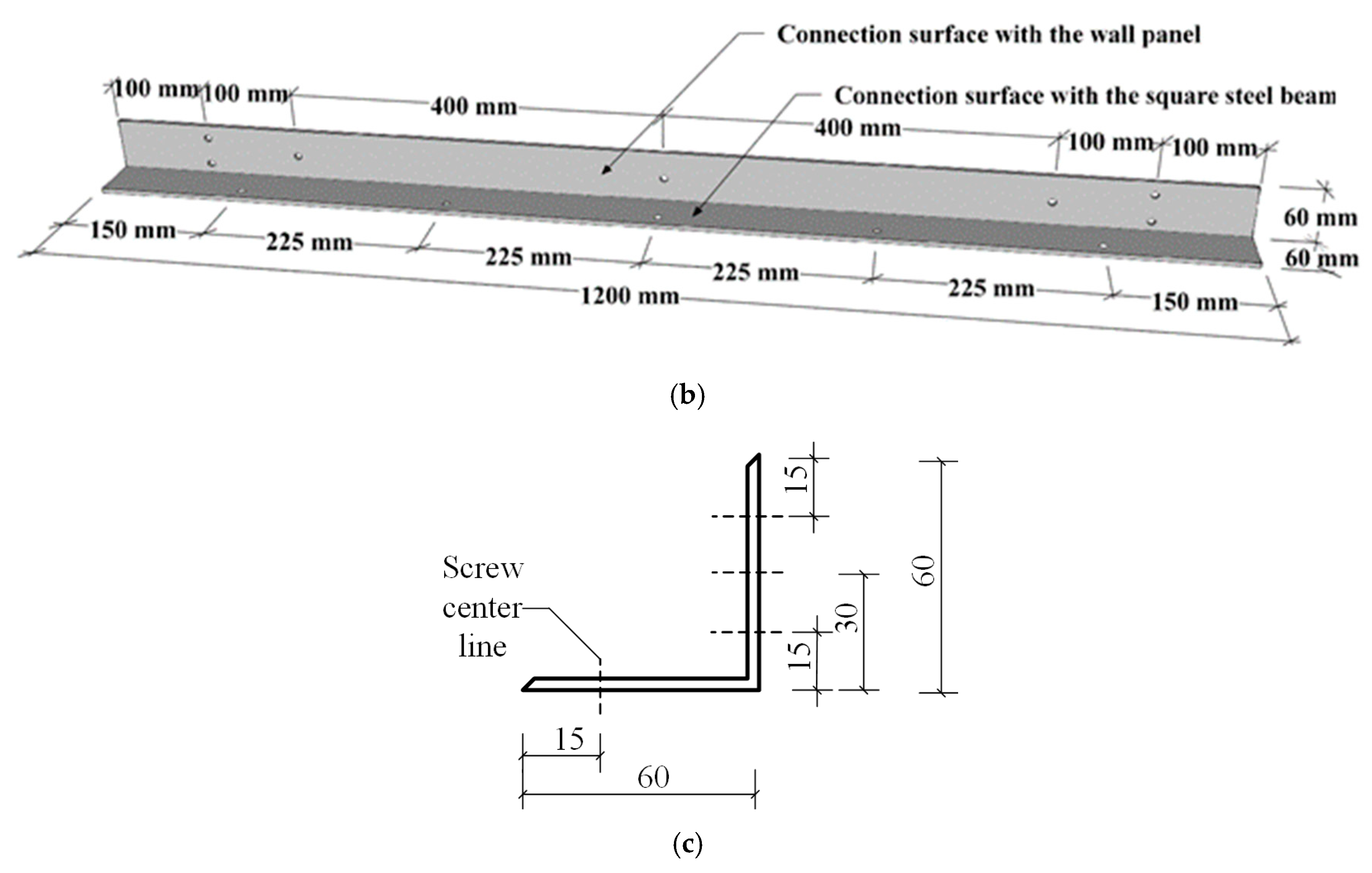
In this study, six specimens were prepared to investigate the effects of the cold-formed light-gauge steel studs arrangement, connector type, connector thickness, the number of screws connected to the steel beam, and the number of connectors on the mechanical performances. The specimens were divided into Type-I and Type-II according to the arrangement of light-gauge steel studs, as shown in Figure 1a,b. The cross-section configuration of the used light-gauge C-channel steel studs is shown in Figure 1c. As shown in Figure 1c, the intermediate stiffener, which is of the circular cross-section with an internal diameter of 5 mm and a radian of 60 degrees, is placed at one-third and two-thirds of the height of the web of the C-channel steel stud. In Type-I, six steel light-gauge steel studs were arranged symmetrically in pairs. In Type-II, six light-gauge steel studs were asymmetrically arranged. Connectors with two different cross-sectional shapes were applied, which were named as the L-shaped steel connector and special-shaped steel connector, as shown in Figure 2 and Figure 3, respectively. Among them, the L-shaped steel connectors are divided into two types according to thickness. The thickness was 1.5 mm and 2.5 mm, respectively. In addition, a full-length design was adopted for an L-shaped steel connector. The numbers of bolts connecting a single connector to the steel beam were set to three and five, as shown in Figure 2a,b. For the special-shaped steel connector, the thickness of the connector was 2.5 mm, and the numbers of single-sided special-shaped steel connectors were set to two and three. In addition, the number of bolts connecting each special-shaped connector to the steel beam was four, including two bolts at the pull-out position and two bolts at the shearing position, as shown in Figure 3a. The detailed experimental plan is listed in Table 1. The specimen was named according to the following rules: the first letter and number represent different LSF wall panels; the second number represents the arrangement of light-gauge C-channel steel studs; the second letter represents the type of the connector; the third number represents the thickness of the connector; the fourth number represents the number of screws for a single connector; the last number represents the number of single-side connectors.

2.2. Test Specimen

Firstly, the LSF wall frame was manufactured, and it consisted of six cold-formed light-gauge steel studs with a spacing of 240 mm and two tracks, which were connected by a series of M6.3 × 15 (in which the 6.3 refers to the outer diameter of the screw, and 15 refers to the length of the screw excluding the nut) self-drilling screws, as shown in Figure 4a. The unrolled C-section steel was selected for the cold-formed light-gauge steel studs and the track. The per unit area of the steel was about 0.1–0.3 kg/m2. The cold-formed light-gauge steel studs have a length of 3110 mm, and the cross-section size is 89 mm × 41 mm × 0.8 mm. The tracks have a length of 1200 mm, and the section size is 90.6 mm × 41 mm × 0.8 mm. The detailed dimensions of the steel frame are shown in Figure 4. The fireproof phenolic boards were then pasted on the upper and lower surfaces of the steel frame with the silicone sealant, as shown in Figure 4b. Subsequently, the gypsum board was pasted on the outside of the fireproof phenolic board, and the inner space of the wall was filled with aluminum silicate cotton, as presented in Figure 4b. Finally, the LSF wall panel was connected to the steel beam through the connector and bolts, as shown in Figure 4b.

2.3. Material Properties
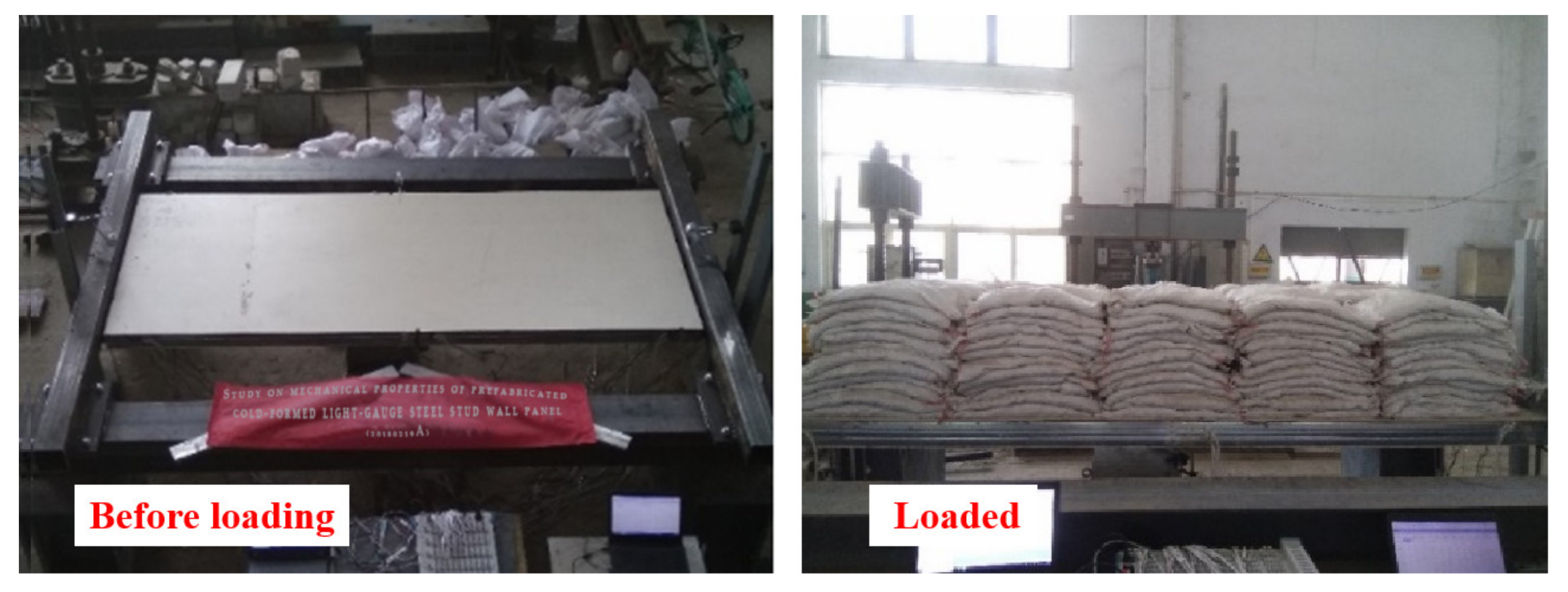
In this study, cold-formed light-gauge steel studs, fireproof phenolic board, silicone structural sealant, steel beam, connector, decorative board, and filling material are used. The cold-formed steel unlipped C-channel studs were produced by a S550GD + Z galvanized steel coil plate with a thickness of 0.8 mm, a flange width of 41 mm, and a web height of 89 mm. The fireproof phenolic board with a thickness of 4 mm was selected as the sheathing board, which was provided by Henan Yongwei Security Co., Ltd. The mechanical properties of the cold-formed steel and phenolic board were tested according to the relevant standard [44,45], and the tested tensile stress–strain curves are shown in Figure 5. The basic performance of the silicone structure sealant was tested by the National Quality Supervision and Inspection Center. The test results of the mechanical properties of the three materials are given in Table 2. The steel beam was made of Q235 steel, the size of which was 150 mm × 150 mm × 6 mm. Two types of connectors were designed to ensure the connection between the wallboard and steel beam, which was made of Q345 steel. The magnesium oxychloride gypsum board with a thickness of 4 mm and aluminum silicate cotton were used as a decorative board and filling material, respectively.

2.4. Loading Plan

In the test, uniform loading of the heavy objects was applied to simulate the effect of wind load. The basic wind pressure was 1.0 kN/m2 following the GB50009-2012 [46], which could meet the design requirements in most areas of China. Subsequently, 1.57, 1.4, and 1.42 were selected for the gust factor, the structural shape factor of wind load, and the height variation coefficient of wind pressure under the worst condition, respectively. The standard value of wind load is calculated according to Equation (1).
w k 1 = β g z × μ s 1 × μ z × ω 01
βgz is the gust factor, μs1 is the structural shape factor of wind load, μz is the height variation coefficient of wind pressure, ω01 is the basic wind pressure, and wk1 is the standard value of wind load, which is 3.121 KN/m2. In this study, the load levels corresponding to different displacements of each specimen can be compared with the wind load standard value of 3.121 KN/m2 for checking the serviceability limit state.
After the single LSF wall panel was connected with the square steel beam through a series of connectors, each specimen was loaded with step-by-step uniform loading. The loading system of the heap load test is listed in Table 3. For each level of load, 15 bags of dry crushed stones were evenly placed on the wall panel, which was equivalent to a uniform load value of 0.402 KN/m2. A gap of 20 mm was maintained between the bags to prevent the arching effect of weights. Each bag was paved to ensure uniform contact with the wall panel. During loading, each level of load lasted 5 min, and the last level of load lasted 30 min. During unloading, the step-by-step method was adopted until the load was zero and the interval time of the step was 3 min. In addition, the applying maximum load of each specimen and loading levels are determined according to the above calculated standard value of wind load, estimated bearing capacity of the wall and connector, and the safety of the test process. The applying maximum loads of all specimens except for specimen QB2-I-Y-2.5-4-3 are larger than the calculated standard value of wind load of 3.121 KN/m2 to check the serviceability limit state of the specimen. For specimen QB2-I-Y-2.5-4-3, its estimated bearing capacity connector is relatively low because of the small thickness of its connector and fewer screws connected to steel beams, so its applying maximum load is set to be relatively low to avoid the possible danger caused by sudden connector failure. Specimens QB1-I-L-2.5-5-1, QB2-I-Y-2.5-4-3, QB3-I-L-1.5-3-1, QB4-I-Y-2.5-4-2, QB5-II-L-2.5-3-1, and QB6-II-Y-2.5-4-3 implemented 8-levels loading (3.216 KN/m2), 12-levels loading (4.824 KN/m2), 4-levels loading (1.608 KN/m2), 10-levels loading (4.020 KN/m2), 8-levels loading (3.216 KN/m2), and 12-levels loading (4.824 KN/m2), respectively. All tests were conducted in the structural laboratory of the School of Civil Engineering, Zhengzhou University. In this study, a total of 150 bags were prepared and the mass of a dry gravel bag was 10 kg. The typical images of the specimen before and after loading are shown in Figure 6. It is worth noticing that under the wind load carried by building structures as specified in the GB50009-2012 [46], wall panels need to meet the requirements of the normal service stage, while the wall panels are commonly in the elastic stage. Thus applying maximum load was designed within the elastic range.

2.5. Measuring Instrument Arrangement

In this study, nine linear variable differential transformers (LVDTs) were set up to obtain the deformations of the whole specimen and LSF wall itself during the loading and unloading process, as shown in Figure 7. Three LVDTs were arranged at the middle and both ends of the wall panel along the width direction to prevent errors caused by the deflection of the specimen during the experiment, as shown in Figure 8. The average value of the three LVDTs was used as the true deflection value at this position. The deformation measured by the LVDT in the middle of the wall panel was obtained as the deflection of the entire specimen. The difference between the measured value of the LVDTs at the middle and both ends of the LSF wall was calculated as the deflection value of the LSF wall itself. In addition, seven resistance strain gauges were arranged at the mid-span positions on both sides of the LSF wall panel along the height direction to check the flat section assumption, as shown in Figure 9.

3. Results and Discussion

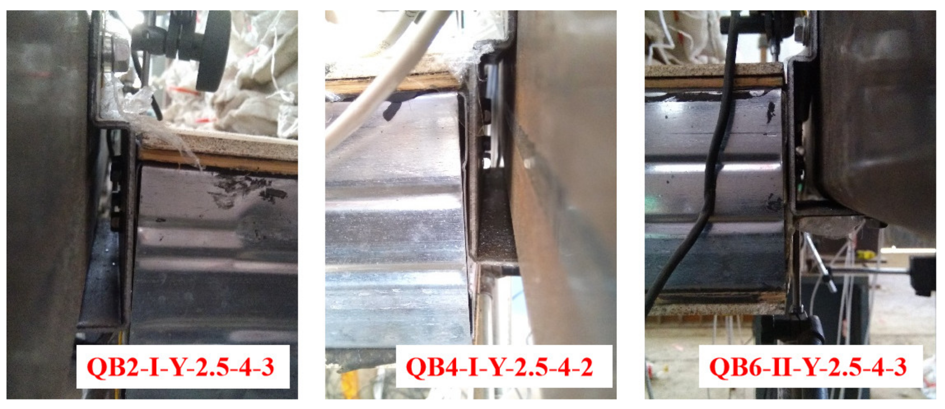
3.1. Experimental Phenomena

The purpose of this test was to explore the out-of-plane elastic mechanical performances of the LSF wall panel and steel frame beam composite structure The fireproof phenolic boards on the upper and lower surfaces of each composite wall were not damaged during the entire loading and unloading process. Yielding or buckling failure in the upper flange and web of light-gauge steel studs at the mid-span position was not observed. In addition, the bonded interface between the fireproof phenolic board and cold-formed light-gauge steel studs was not damaged. Therefore, the LSF wall of each specimen was considered to be in an elastic state during loading and unloading. For the specimens with L-shaped connectors, a larger displacement was observed at the position of the L-shaped connector, as shown in Figure 10. Meanwhile, the self-tapping screws connecting the connector and steel beam had obvious restraint deformation. The entire connector exhibited waviness along the width direction of the wall panel, as shown in Figure 11. For the specimens with the special-shaped connectors, no obvious deformation was observed at the position of the connector, as shown in Figure 12.

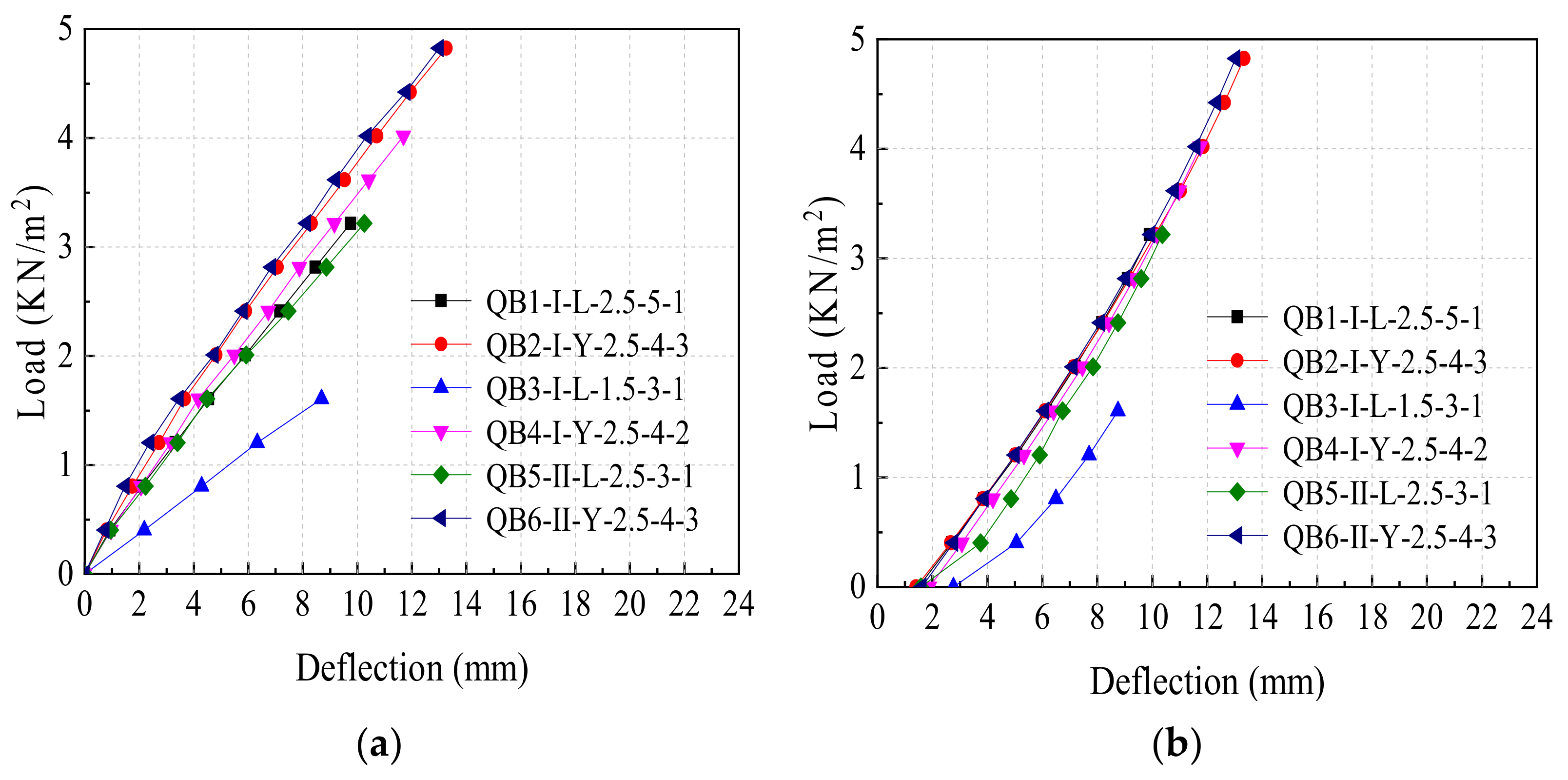
3.2. Load-Span Deflection Curve

Figure 13a presents the load-span deflection curves of different types of specimens during loading. For each type of specimen, the load increased linearly with the increase in the displacement during the loading process, and the slope of the load-deflection curve of each specimen was different due to the difference in the test parameter settings. It needsed to be emphasized that the slope of the curve for specimen QB3-I-L-1.5-3-1 was obviously smaller than that of other specimens, which indicated that the connector thickness had the most significant influence on the overall stiffness of the specimen. The main reason was that the constraint ability of the connector to the wall panel decreased as the thickness of the connector decreased. Figure 13b presents the load-span deflection curves of different types of specimens during unloading. In general, the load-span deflection curve of each type of specimen showed a non-linear decline as the load decreased and a certain residual deformation was observed for each specimen when the load decreased to zero, which indicated that the plastic deformation occurred in the connection position of the specimen during the loading process and there may be some clearance at the screws. According to the measured data in the mid-span deflection curve of each specimen, the bending stiffness of each specimen could be calculated by using Equation (2):
B = E I k = w b l 4 f
where B is the bending stiffness of the specimen, E is the equivalent elastic modulus of the mid-span section of the wall (N/m2), I is the equivalent moment of inertia of the mid-span section of the wall (m4), k is the coefficient that characterizes the restraint at both ends and load form (dimensionless), w is the applied area load of each level (KN/m2), b is the width of the specimen (m), l is the effective span of the specimen (m), and f is the measured mid-span deflection of the specimen (mm).
The maximum load, bending stiffness, and mid-span deflection under the maximum load of each specimen are listed in Table 4. The bending stiffness of the specimen with a special-shaped connector was greater than that of the specimen with an L-shaped connector. Meanwhile, the unloading stiffness of the specimen was greater than the loading stiffness of the corresponding specimen, which indicated that the screw position had a certain gap before loading, and the screw hole had slight plastic deformation during the loading process. It can be considered that part of the gap and plastic deformation were eliminated, and the remaining deformation was the elastic deformation of the specimen in the unloading process. Therefore, the unloading stiffness should be the elastic bending stiffness of the specimen. In addition, by comparing specimens QB2-I-Y-2.5-4-3 and QB6-II-Y-2.5-4-3, the arrangement of the light-gauge steel studs had almost no effect on the overall elastic bending stiffness of the specimen. Furthermore, by comparing specimens QB1-I-L-2.5-5-1 and QB5-II-L-2.5-3-1, as well as QB3-I-L-1.5-3-1 and QB5-II-L-2.5-3-1, increasing the number of self-tapping screws from three to five, or increasing the thickness of the L-shaped connector from 1.5 mm to 2.5 mm, can improve the overall elastic bending stiffness of the specimen. In addition, by comparing specimens QB2-I-Y-2.5-4-3 and QB4-I-Y-2.5-4-2, increasing the number of special-shaped connectors from two to three can improve the overall bending stiffness of the specimen, and the stiffness contribution of a single special-shaped connector can also be increased.

3.3. Bending Stiffness

3.3.1. Arrangement of Light-Gauge Steel Studs

Figure 14a shows the load-span deflection curves of each LSF wall panel during loading. The six wall panels are in a state of linear elasticity and the load increased linearly with the increase of displacement during the loading process. Among them, the slope of the curve for wall panel QB3-I-L-1.5-3-1 was significantly smaller than that of the other wall panels, and the slope of curves for the other five wall panels was similar. Figure 14b shows the load-span deflection curves of each LSF wall panel during unloading. The load decreased non-linearly with the decrease in displacement. In general, the slope of curves for the six wall panels has little difference during the unloading process. Therefore, the small slope of the curve for wall panel QB3-I-L-1.5-3-1 was due to certain inelastic deformation and test errors during the loading process.
Table 5 lists the maximum load, bending stiffness, and mid-span deflection under the maximum load of each LSF wall panel. According to the calculation method and analysis in Section 3.2, the elastic bending stiffness of the wall panel should be the unloading stiffness. It could be found that the bending stiffness of the wall panel when the light-gauge steel studs were arranged asymmetrically was slightly greater than that of the wall penal when the light-gauge steel studs were arranged symmetrically. The difference between the average stiffness of wall panels with two arrangements was only 3.2%. Therefore, it could be considered that the arrangement of the light-gauge steel studs has no significant effect on the stiffness of the wall panel. It was because the fireproof phenolic board plays a lateral restraint role on the cold-formed light-gauge steel studs as the sheathing board. Thus, the overall mechanism of the LSF wall panel was increased.

3.3.2. Connection Mode

Table 6 lists the bending stiffness of each specimen, the bending stiffness of the wall panel itself, and the ratio of bending stiffness of the specimen to the wall. The overall bending stiffness of the specimen is not equal to the elastic bending stiffness of the wall panel, which indicates that the connection mode between the wall panel and the steel beam has a certain influence on the stiffness of the specimen. For specimens with L-shaped connectors, the bending stiffness of specimens was generally less than the bending stiffness of the wall panel itself. For specimens with special-shaped connectors, the bending stiffness of specimens was generally greater than the bending stiffness of the wall panel itself. This phenomenon indicates that the connection rigidity of the special-shaped connector was larger, and the constraint capacity of the special-shaped connector to the wall panel was greater than that of the L-shaped connector.

3.4. Strain Distribution

Figure 15 shows the strain curve of the mid-span section along the height direction. The longitudinal coordinate represents the height of the mid-span section of the wall panel. Zero on the Y-axis represents the bottom elevation of the mid-span section. The horizontal coordinate represents the strains at different heights of the section under different levels of loads. The six wall panels show the same phenomenon, so QB1-I-L-2.5-5-1 and QB5-II-L-2.5-3-1 were analyzed as examples. For QB5-II-L-2.5-3-1, there were only five measurement points because the test data cannot be collected accurately. It can be observed that the strain was not in a straight line under different levels of loads. The strain difference between fireproof phenolic board and flange of light-gauge steel studs gradually increased as the load increased. To further compare the relationship of the strain between the flange of light-gauge steel studs and fireproof phenolic under different levels of loads, the strain-load curves of the upper and lower flanges of light-gauge steel studs and the corresponding upper and lower fireproof phenolic boards are shown in Figure 16. The strain of the flange of the light-gauge steel studs is greater than the corresponding strain of fireproof phenolic board under different levels of loads. With the increase in load, the rate of the strain increase on fireproof phenolic board is less than that of the flange of the light-gauge steel studs. The main reason is that the silicone sealant layer between the flange of the light-gauge steel studs and the fireproof phenolic board has a large longitudinal shear deformation, which results in the relative slip between the flange of the light-gauge steel studs and the fireproof phenolic board. Therefore, the strain distribution of the LSF wall panel does not conform to the flat section assumption.

4. Theoretical Study of the Stress of LSF Wall Panels

4.1. Symmetric Slip Theory

4.1.1. The Basic Assumptions

In order to facilitate calculation, the following assumptions are made for the structural stress model, according to the characteristics of the LSF wall based on the assumption of the steel-concrete composite beam.
(1)
Fireproof phenolic boards, silicone sealant, and cold-formed light-gauge steel studs are all elastomers. Phenolic boards and the light-gauge steel studs are in continuous and uniform contact through the silicone sealant in the longitudinal direction and maintain the same curvature. Furthemore, the longitudinal slip is a linear elastic process.
(2)
Under the condition of small elastic deformation, the top and lower interfaces are stressed symmetrically.
(3)
The out-of-plane stiffness, the bending moment, and the shear stress of the fireproof phenolic board can be ignored.

4.1.2. Differential Equation of Symmetrical Slip

Figure 17 shows the mechanical model of the wall under the out-of-plane distributed load. The wall and the connectors are connected by self-drilling screws and the boundary at both ends of the wall was considered to be articulated approximately. Figure 18 presents the slip analysis for micro-segments.
According to the stress analysis of the micro-segment, the static equilibrium equation of the top fireproof phenolic board in the x-direction was obtained by Equation (3):
τ ( x ) = 1 b i d N f ( x ) d x
where τ(x) is the slip shear stress, ∑bi is the total bonding width of wall width, and Nf(x) is the axial stress of single-sided phenolic boards. According to Assumption (1), τ(x) is expressed as:
τ ( x ) = G s ( x ) a
where G is the shear modulus of adhesive, s(x) is the slip, and a is the thickness of the adhesive layer. The slip is obtained by the simultaneous of Equations (3) and (4), as shown in Equation (5).
s ( x ) = a G b i d N f ( x ) d x
The slip strain is obtained by taking the first derivative of the slip with respect to x, which is expressed in Equation (6). The slip strain can also be expressed by Equation (7).
ε ( x ) = a G b i d 2 N f ( x ) d x 2
ε ( x ) = ε f ( x ) ε s ( x )
ε(x) is the slip strain, εf(x) is the longitudinal strain of the phenolic board, and εs(x) is the longitudinal strain of the light-gauge steel studs. According to Assumption (3), the longitudinal strain at the centroid of the fireproof phenolic board at the top compression position can be expressed as follows:
ε f ( x ) = N f ( x ) E f A f
where Ef is the elastic modulus of the phenolic board, and Af is the cross-section area of the single side phenolic board. Because the axial forces of the top and lower fireproof phenolic boards are self-balanced, the longitudinal strain at the top flange of cold-formed light-gauge steel studs is expressed as follows:
ε s ( x ) = M s ( x ) E s I S h s 2
where Es is the elastic modulus of the light-gauge steel studs, Is the total moment of inertia of the section of light-gauge steel studs, hs is the height of the section of light-gauge steel studs, and Ms(x) is the total bending moment of the section of light-gauge steel studs. The simultaneous of Equations (7)–(9) is expressed as follows:
ε ( x ) = M s ( x ) E s I s h s 2 N f ( x ) E f A f
The total bending moment on the combined section of the LSF wall panel is the sum of the bending moment of the cold-formed light-gauge steel studs and the couple moment formed by the axial force of the fireproof phenolic board, which can be obtained according to Assumption (2) and (3), as shown in Equation (11):
M ( x ) = M s ( x ) + 2 N f ( x ) d c
where M(x) is the total bending moment of the section, and dc is the distance between the centroid of the section of light-gauge steel studs and the centroid of the phenolic board section. The differential equation of elastic slip of LSF wall can be expressed by Equation (12), which can be obtained by the simultaneous of Equations (6), (10) and (11).
N f ( x ) λ 2 N f ( x ) + η 1 2 d c M ( x ) = 0
Among them:
λ = η 1 + η 2
η 1 = G h s d c b i a E s I s
η 2 = G b i a E f A f

4.1.3. Solution of the Mechanical Characteristic Quantity of Interface Slip under Load

According to the distribution load model shown in Figure 17, the section bending moment can be expressed by Equation (16).
M ( x ) = 1 2 q ( l 2 4 x 2 )
According to the symmetry of the force model, the boundary condition can be obtained by substituting Equation (16) into Equation (12).
s ( 0 ) = a G b i d N f ( x ) d x | x = 0 = 0
ε f ( 0.5 l ) = N f ( 0.5 l ) E f A f | x = 0.5 l = 0
A general solution can be obtained by solving differential Equation (12):
N f ( x ) = η 1 q 2 λ 4 d c e λ x + e λ x e 0.5 λ l + e 0.5 λ l 1 + η 1 q 4 λ 2 d c l 2 4 x 2
The slip shear stress, slip, and slip strain of wall section under distribution load can be obtained by substituting Equation (19) into Equations (3), (5) and (6), as shown in Equations (20)–(22), respectively.
τ ( x ) = η 1 q 2 λ 2 d c b i e λ x e λ x λ ( e 0.5 λ l + e 0.5 λ l ) + x
s ( x ) = a η 1 q 2 G λ 2 d c b i e λ x e λ x λ ( e 0.5 λ l + e 0.5 λ l ) + x
ε ( x ) = a η 1 q 2 G λ 2 d c b i 1 e λ x + e λ x e 0.5 λ l + e 0.5 λ l
Similarly, the results under other out-of-plane loads can also be calculated. Figure 19 shows the distribution curves of the slip shear stress, slip, and slip strain of the wall along the direction of the wall span under the distribution load. It can be observed that the slip shear stress and slip are odd functions, and the maximum appears at the end of the panel in the case of symmetrical out-of-plane load and boundary conditions. In addition, the slip strain is an even function, and the maximum appears at the span of the panel. The results are consistent with the results of a bending slip of steel beams reinforced by FRP and CFRP [47,48,49,50,51,52,53,54]. In these studies, the peak of the slip’s normal stress (de-bonding stress) also occurs at the panel end. Therefore, in practical engineering applications, it is suggested to add self-drilling screws on the top and lower of the LSF wall panel to make the sheathing boards connected with the light-gauge steel studs and to prevent the de-bonding and shear failure of the adhesive interface caused by out-of-plane wind load and temperature.

4.1.4. Composite Section Stiffness and Sheathing Effect Coefficient of LSF Wall Panels

According to Assumption (2) in Section 4.1.1, the centroid of the composite section is consistent with the centroid of the cold-formed light-gauge steel studs due to the composite section of the wall being stressed symmetrically under the out-of-plane load. Therefore, the contribution of the cold-formed light-gauge steel studs to the stiffness of the composite section is not changed, and the slip effect only affects the utilization rate of the section composite stiffness of the fireproof phenolic board. Based on the direct strength method, the whole width of the phenolic board is considered as a whole, and the effective flange width of the phenolic board is not calculated to simplify the calculation method. Therefore, this method is different from the reduced stiffness method. The stiffness reduction coefficient m of the fireproof phenolic board is introduced, which is called the sheathing effect coefficient.
The composite section stiffness of LSF wall panels can be defined as:
B = E s I s + m I f
where If is the moment of inertia of the whole section of the top and lower phenolic board to the centroid of the composite section after conversion according to the elastic modulus.
I f = 2 A f d c 2
The deformation compatibility equation for the mid-span of the LSF wall panel is shown in Equation (25):
δ 0 I S + I f I S + m I f = δ 0 + Δ f
where Δf is the additional deflection in the mid-span of the wall, and δ0 is the mid-span deflection of the wall without considering slip. The expression of sheathing effect coefficient is obtained by the inverse solution:
m = δ 0 I S I f Δ f δ 0 + Δ f
The additional curvature can be obtained by Equations (27) and (28) to obtain the additional deflection.
Δ κ = ε ( x ) 2 d c
Δ κ ( x ) = Δ f ( x )
Under Uniformly distributed load out-the-plane, the simultaneous result of Equations (22), (27) and (28) was substituted into the boundary conditions.
Δ f ( 0 ) = 0
Δ f ( 0.5 l ) = 0
The additional deflection of mid-span under distribution load is obtained by solving the differential Equation (28), as shown in Equation (31).
Δ f = a η 1 q 4 G λ 2 d c 2 b i [ l 2 8 + 2 λ 2 ( e 0.5 λ l + e 0.5 λ l ) 1 λ 2 ]
The sheathing effect coefficient under distribution load was obtained by substituting Equation (31) into Equation (26). In the same way, the sheathing effect coefficient under the action of other forms of out-of-plane loading can also be obtained. It can be seen that the sheathing effect coefficient has nothing to do with the load, but is only related to the physical, geometric, load form, and boundary conditions of the wall. Furthermore, the coefficient is always less than 1. Combining with Equation (23), it can be observed that the coefficient essentially reflects the contribution or utilization rate of the sheathing board to the stiffness of the composite section of the wall. A direct macroscopic deflection response coefficient m is used to express the slip effect because it is difficult to measure the mechanical response of the slip interface directly. Furthermore, the correctness of the theory in this paper can be proved by comparing the theoretical results with the experimental results. The calculated sheathing effect coefficient m was obtained by substituting the measured geometrical physical parameters of each specimen into Equations (13)–(15), (26), and (31). The measured stiffness is calculated through the calculated m and the measured mid-span deflection of the specimen. The measured sheathing effect coefficient m0i can then be calculated by substituting B0i into Equation (23).
Table 7 shows the ratio of the calculated value to the measured value of the sheathing effect coefficient. It can be concluded that the average value of the ratio is 0.88 and the coefficient of variation is 0.0584. Generally, the calculated value of m is less than the measured value, which is conservative. The reason is that a decorative layer on the actual wall and the connectors can provide small rotational stiffness for the support, which is not considered in the calculation.

4.2. Calculation of Elastic Deflection of LSF Wall Panels and Bending Normal Stress of Longitudinal Light-Gauge Steel Studs under Wind Load

4.2.1. Calculation of Mid-Span Elastic Deflection of LSF Wall Panels

The elastic deflection equation of the LSF wall with simple support at both ends under distribution load can be obtained by substituting Equation (23) and the simplified wind load model into the structural mechanical deflection equation.
f = 5 q l 4 384 B
where:
B = E s I s + m I f
m = δ 0 I S I f Δ f δ 0 + Δ f
Δ f = a η 1 q 4 G λ 2 d c 2 b i [ l 2 8 + 2 λ 2 ( e 0.5 λ l + e 0.5 λ l ) 1 λ 2 ]
λ = η 1 + η 2
η 1 = G h s d c b i a E s I s
η 2 = G b i a E f A f

4.2.2. Calculation of Elastic Bending Normal Stress of Longitudinal Light-Gauge Steel Studs

According to the Steel Structure Design Standard, the top and lower of cold-formed light-gauge steel studs are pasted with sheathing boards to prevent the lateral deformation of the light-gauge steel studs, so the overall bending or buckling of the wall is not considered. In the elastic stage, the bending normal stress equation of the top and lower flange of light-gauge steel studs with simple supports at both ends of LSF wall panels under distribution load can be obtained, as shown in Equation (33).
σ s = M y I = M h s 2 B E s = M h s E s 2 B

4.2.3. Strength Checking of the Adhesive Layer between Phenolic Boards and Light-Gauge Steel Studs

The maximum slip shear stress and slip normal stress (also termed as de-bonding stress, which is not considered in this paper) appear at the support position, while the principal stress formed by slip shear stress and slip normal stress will cause local damage of the adhesive layer near the support. Therefore, it is necessary to check the strength of the adhesive layer. The checking method is according to the GB51367-2019 [55].

4.3. Comparison between the Proposed Method and the Existing Methods

4.3.1. Transformed-Section Method without Considering Interface Slip

This method is an early method to calculate the deflection of the composite beam and slab [56,57], which is referred to as the transformed-section method. The cross-section of the two materials is converted to that of one material according to the elastic modulus. In the cross-section conversion, the flange plate within the effective width is converted instead of the full section of the flange plate, without considering the slip effect generated by the interface between the two materials.
Figure 20 shows the effective width and the converted width. The effective width of the flange plate is calculated by:
b e = b 0 + b 1 + b 2
where b0 is the width of the top flange of the beam without panel support, b1 and b2 are the calculated width of the flange plate on both sides of the beam, and the smaller value of 1/6 of the beam span l and 6 times of the flange plate thickness h1 is taken as b1 and b2, respectively. The calculation equation for the converted width of the flange plate is as follows:
b e q = b e α E
where αE is the ratio of elastic modulus of beam material Es to the elastic modulus of flange plate material Ef. When the combined section of the two materials is converted into the section of the beam material, the deflection and section stress can be calculated according to the material mechanics method.

4.3.2. Reduced Stiffness Method Considering Interface Slip

This method is used to calculate the deformation of the composite beam and slab in China’s current standard GB 50017-2017 [58,59,60], which is called the reduced stiffness method in this paper. Compared with the transformed-section method, the slip effect caused by the interface of two materials is considered with this method. In addition, the stiffness reduction coefficient to reflect the slip effect is introduced.
Based on the transformed-section method, the calculation equation of reduced stiffness is obtained according to Equation (36):
B = E s I e q 1 + ζ
where Es is the elastic modulus of beam material, Ieq is the moment of inertia of the converted section, and ζ is the stiffness reduction coefficient, which is calculated according to the following equation:
ζ = η [ 0.4 3 ( α l ) 2 ]
η = 36 E s d c p A 0 n s k h l 2
α = 0.81 n s k A 1 E 1 I 0 p
A 0 = A c f A α E A + A c f
A 1 = I 0 + A 0 d c 2 A 0
I 0 = I + I c f α E
where Acf is the flange plate section area within the effective width, A is the beam cross-section area, I is the moment of inertia of the beam section, Icf is the moment of inertia of flange plate section within the effective width, dc is the distance between the centroid of the beam section and the centroid of the flange plate section, h is the height of the composite section, l is the calculated span, k is the stiffness coefficient of the connector between the flange plate and the beam, p is the average spacing of connectors, and ns is the number of longitudinal columns of connectors. In the elastic stage, the elastic resistance moment of the reduced section considering the interface slip [45] is as follows:
W = W e q 1 + ξ ζ
where Weq is the elastic resistance moment of the section calculated according to the transformed-section method and ζ is the stiffness reduction coefficient, which is calculated as follows:
Single interface sliding:
ξ = h s ( h A w + 2 h f A f t ) 6 I e q
According to the superposition principle, when double-interface slip:
ξ = h s ( h A w + h f 1 A f t + h f 2 A f s ) 3 I e q
where Aw is the section area of steel beam web; Aft and Afs are the section area of the top and lower flange of steel beam, respectively; hf1 and hf2 are the thickness of the top and lower flange, respectively.
In this method, the discrete screws connection is adopted for the connection between the flange plate and the beam. However, the structural sealant was selected for the connection in our study. To make a comparison with the theory in this paper, the connection stiffness of two different connection modes is converted to be equivalent. In the derivation of the reduced stiffness method, it is assumed that the interface horizontal shear stress is proportional to the relative slip [45], as shown in Equation (46).
p v = n s k s
where v is the horizontal shear stress per unit length, which can be obtained by Equation (47).
v = τ b i
Equation (48) is obtained by substituting Equation (46) into Equation (4), and then combining with Equation (47).
n s k p = G b i a
In the reduced stiffness method, the LSF wall panel data in this paper can be calculated with Equation (48).

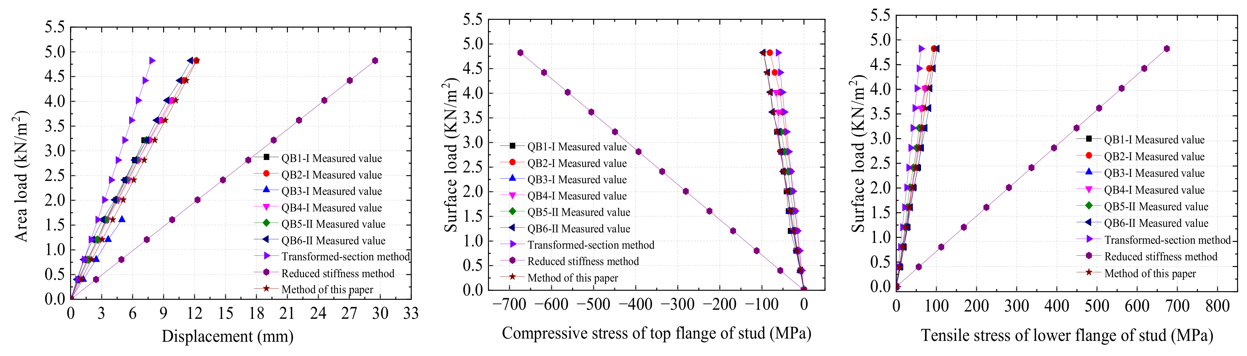
4.3.3. Comparison of Calculated Results

The measured material and geometric parameters of the specimens are substituted into the above two existing theoretical calculation methods and the calculation method of this paper to calculate the mid-span deflection of the wall. The results are then compared with the measured values. Figure 21 shows that the results calculated by the transformed-section method and the reduced stiffness method are quite different from the experimental results. The results calculated by the reduced stiffness method are too conservative. However, the influence of the interface slip is not considered in the transformed-section method, which is unsafe. The results indicate that the reduced stiffness method and the transformed-section method are not suitable for calculating the elastic deflection and bending stress of LSF wall panels.
The influence of different arrangements of cold-formed light-gauge steel studs is not considered in the theoretical derivation in Section 4, because the six specimens have the same parameters except for the asymmetric layout of the light-gauge steel studs of QB5-II-L-2.5-3-1 and QB6-II-Y-2.5-4-3. It can also be observed from the test results in Section 3.2 that the overall stiffness of the composite wall with a symmetrical arrangement of light-gauge steel studs is basically the same as that with an asymmetric arrangement of light-gauge steel studs, due to the sheathing effect of the fireproof phenolic board.
Therefore, the calculated results of the three methods under each level of load are compared with the measured average values of the six specimens. The calculated and measured results of mid-span deflection of specimens, compressive stress at top flange of longitudinal light-gauge steel studs in mid-span, and the tensile stress at lower flange of longitudinal light-gauge steel studs in the mid-span are shown in Table 8, Table 9 and Table 10, respectively.
Table 8, Table 9 and Table 10 show that the mid-span deflection of wall panels and the stresses at the top and lower flanges of longitudinal light-gauge steel studs in mid-span calculated by the transformed-section method are less than the measured values in the test under each level of load. The ratios of average calculated values to the measured values in the test for the mid-span deflection of the wall panel, the stress at the top flange, and the stress at the lower flange are 0.714, 0.701, and 0.631, respectively. This phenomenon occurs because the transformed-section method only converts the two materials into one material within the effective width and takes no account of the slip effect of the two materials, which means that the result tends to be unsafe.
The mid-span deflection and the stress at the top and lower flanges of longitudinal light-gauge steel studs in the mid-span of wall panels calculated by the reduced stiffness method are greater than the measured values. The ratios of average calculated values to the measured values for the mid-span deflection of the wall panel, the stress at the top flange, and the stress at the lower flange are 2.689, 7.659, and 6.892, respectively. The reduced stiffness method has good accuracy in a steel-concrete beam structure [61], but the method used in this paper is obviously too conservative. The reason is that the stiffness reduction method is carried out within the effective width of the flange plate material, which is better for large spacing between the steel beam and steel beam in steel-concrete composite beam and large flange width relative to steel beamwidth. However, the accuracy of the wall with sheathing boards and with multiple cold-formed light-gauge steel studs is poor.
The calculated values of the theoretical method proposed in this paper are closer to the experimental results, compared with the transformed-section method and the reduced stiffness method. The ratios of the calculated values to the measured value of the mid-span deflection, the measured value of the compression stress of the top flange of the longitudinal light-gauge steel studs in the mid-span, and the tensile stress of the lower flange of the longitudinal light-gauge steel studs in the mid-span are 1.114, 1.094, and 0.984, respectively, with the variation coefficients of 5.0%, 6.4%, and 5.5%, respectively. Therefore, among the three calculation methods, the method based on the symmetrical slip of interface proposed in this paper is more suitable for the calculation of the elastic deflection and elastic bending stress of LSF wall panels used in this study. In addition, the calculation process is simpler than the reduced stiffness method.

5. Conclusions

This paper proposed a new type of composite wall panel, which is made by bonding the phenolic fireproof panel and cold-formed light-gauge steel studs with a structural adhesive. The proposed prefabricated LSF wall panel has the advantages of lightweight, fireproof, and easily connected. A distribution load test was used to simulate the effect of an out-of-plane wind load to investigate the force performance of the composite wall and the surrounding steel structure under different connection methods. In addition, a new stiffness degradation model was proposed for the composite wall panel with the consideration of the sheathing board effect. The main conclusions obtained in this paper are as follows:
  • In the elastic stress stage under out-of-plane loads, the asymmetric arrangement of light-gauge steel studs of the LSF wall does not affect the overall elastic bending stiffness of wall panels. Thus, the symmetrical arrangement is recommended for practical applications.
  • In the elastic stress stage under out-of-plane loads, increasing the thickness of the L-shaped connect-or and the number of self-tapping screws can improve the out-of-plane stiffness of the prefabricated LSF wall system. The overall out-of-plane stiffness of the prefabricated LSF wall system and the stiffness contribution of a single special-shaped connector can be increased by increasing the number of special-shaped connectors from two to three. The symmetrical arrangement of light-gauge steel studs of LSF wall is beneficial to improving the out-of-plane stiffness of the connectors. In addition, special-shaped connectors have greater out-of-plane stiffness than L-shaped connectors.
  • Based on the sheathing effect of the wall panel and the symmetric slip theory of the interface between the fireproof phenolic board and light-gauge steel studs, the equations for calculating the elastic deflection in span and the elastic bending stress of light-gauge steel studs of the LSF wall are derived theoretically under out-of-plane loading. Compared with the transformed-section method and the reduced stiffness method in China’s steel structure design standards, the results obtained from the calculation of the method proposed in this paper are closer to the experimentally measured data.

Author Contributions

Conceptualization, G.Z. and K.L.; methodology, G.Z. and K.L.; Software, W.C. and D.Z.; validation, G.Z.; formal analysis, D.Z.; investigation, D.Z.; data curation, W.C.; writing—original draft preparation, W.C.; writing—review and editing, W.C.; supervision, K.L.; funding acquisition, K.L. All authors have read and agreed to the published version of the manuscript.

Funding

This research was funded by China Postdoctoral Science Foundation (Grant No. 2020M672236), Ministry of housing and urban rural development science and technology program of China (Grant Nos. 2019-K-059, K2124), and Support Project for Young Talents-Enterprise Cooperation Innovation Team of Zhengzhou University.

Institutional Review Board Statement

Not applicable.

Informed Consent Statement

Not applicable.

Data Availability Statement

Not applicable.

Conflicts of Interest

The authors declare no conflict of interest. The funders had no role in the design of the study; in the collection, analyses, or interpretation of data; in the writing of the manuscript, or in the decision to publish the results.

References

  1. Sutarja, I.N.; Ardana, M.D.W.; Putra, I.D.G.A.D. The Post-disaster House: Simple Instant House using Lightweight Steel Structure, Bracing, and Local Wood Wall. Int. J. Eng. 2021, 34, 348–354. [Google Scholar] [CrossRef]
  2. Nadim, W.; Goulding, J.S. Offsite production in the UK: The way forward? a UK construction industry perspective. Constr. Innov. 2010, 10, 181–202. [Google Scholar] [CrossRef]
  3. Wang, H.; Zhang, Y.-Q.; Gao, W.-J.; Kuroki, S. Life cycle environmental and cost performance of prefabricated buildings. Sustainability 2020, 12, 2609. [Google Scholar] [CrossRef] [Green Version]
  4. Chiang, Y.H.; Chan, E.H.W.; Ka-Leung Lok, L. Prefabrication and barriers to entry-a case study of public housing and institutional buildings in Hong Kong. Habitat Int. 2006, 30, 482–499. [Google Scholar] [CrossRef]
  5. Hong, J.-K.; Shen, Q.-P.; Li, Z.-D.; Zhang, B.-Y.; Zhang, W.-Q. Barriers to promoting prefabricated construction in china: A cost–benefit analysis. J. Clean. Prod. 2018, 172, 649–660. [Google Scholar] [CrossRef]
  6. Liu, W.-H.; Zhang, H.; Wang, Q.; Hua, T.-R.; Xue, H. A review and scient metric analysis of global research on prefabricated buildings. Adv. Civ. Eng. 2021, 2021, 8869315. [Google Scholar] [CrossRef]
  7. Zhou, M.; Chen, Y.-Y.; Su, X.-L.; An, L. Rapid construction and advanced technology for a COVID-19 field hospital in Wuhan, China. Civ. Eng. 2021, 174, 29–34. [Google Scholar] [CrossRef]
  8. Bhatti, A.Q.; Wahab, A. Analysis and design of emergency field isolation hospital building using innovative rapidly construction prefabricated units to treat patients infected with COVID-19. Innov. Infrastruct. Solut. 2021, 6, 90. [Google Scholar] [CrossRef]
  9. Chinese Standard GB/T51232-2016; Technical Standard for Prefabricated Steel Structure Building. China Architecture and Building Press: Beijing, China, 2016.
  10. Chinese Standard JG/T544-2018; Light-Gauge Steel Framing Wall Panel. Standards Press of China: Beijing, China, 2018.
  11. Vitale, P.; Spagnuolo, A.; Lubritto, C.; Arena, U. Environmental performances of residential buildings with a structure in cold formed steel or reinforced concrete. J. Clean. Prod. 2018, 189, 839–852. [Google Scholar] [CrossRef]
  12. Dani, A.A.; Roy, K.; Masood, R.; Fang, Z.; Lim, J.B.P. A Comparative Study on the Life Cycle Assessment of New Zealand Residential Buildings. Buildings 2022, 12, 50. [Google Scholar] [CrossRef]
  13. Dias, Y.; Mahendran, M. Shape optimisation of cold-formed steel framed wall studs with sheathing restraints. Thin-Walled Struct. 2020, 158, 107135. [Google Scholar] [CrossRef]
  14. Roy, K.; Lau, H.H.; Ting, T.; Chen, B.; Lim, J.B.P. Flexural capacity of gapped built-up cold-formed steel channel sections including web stiffeners. J. Constr. Steel Res. 2020, 172, 106154. [Google Scholar] [CrossRef]
  15. Chen, B.; Roy, K.; Fang, Z.; Uzzaman, A.; Chi, Y.; Lim, J.B.P. Web crippling capacity of fastened cold-formed steel channels with edge-stiffened web holes, un-stiffened web holes and plain webs under two-flange loading. Thin-Walled Struct. 2021, 163, 107666. [Google Scholar] [CrossRef]
  16. Ananthi, G.B.G.; Vishuvardhan, S.; Knight, G. Experimental, theoretical and numerical study on thin walled steel single and compound channel sections in axial compression. Indian J. Eng. Mater. Sci. 2015, 22, 570–580. [Google Scholar]
  17. Ananthi, G.B.G. A Study on Cold-Formed Steel Compound Angle Section Subjected to Axial Compression. KSCE J. Civ. Eng. 2018, 22, 1803–1815. [Google Scholar] [CrossRef]
  18. Ananthi, G.B.G.; Palani, G.S.; Iyer, N.R. Numerical and Theoretical Studies on Cold-Formed Steel Unlipped Channels Subjected to Axial Compression. Lat. Am. J. Solids Struct. 2015, 12, 1–17. [Google Scholar] [CrossRef] [Green Version]
  19. Roy, K.; Lim, J.B.P. Numerical investigation into the buckling behaviour of face-to-face built-up cold-formed stainless steel channel sections under axial compression. Structures 2019, 20, 42–73. [Google Scholar] [CrossRef]
  20. Ananthi, G.B.G.; Roy, K.; Lim, J.B.P. Tests and Finite Element Modelling of Cold-Formed Steel Zed and Hat Section Columns Under Axial Compression. Int. J. Steel Struct. 2021, 21, 1305–1331. [Google Scholar] [CrossRef]
  21. Ananthi, G.B.G.; Roy, K.; Lim, J.B.P. Experimental and numerical study of an innovative 4-channels cold-formed steel built-up column under axial compression. Steel Compos. Struct. 2022, 42, 513–538. [Google Scholar] [CrossRef]
  22. Ananthi, G.B.G.; Roy, K.; Lim, J.B.P. Behaviour and strength of back-to-back built-up cold-formed steel unequal angle sections with intermediate stiffeners under axial compression. Steel Compos. Struct. 2022, 42, 1–22. [Google Scholar]
  23. Shi, Y.; Ran, X.-W.; Xiao, W.; Ke, K.; Xiang, Y.; Deng, R. Experimental and numerical study of the seismic behavior of cold-formed steel walls with diagonal braces. Thin-Walled Struct. 2020, 159, 107318. [Google Scholar] [CrossRef]
  24. Wu, H.-H.; Sui, L.; Zhou, T.-H.; Lu, L.-F.; Li, X.-H. Estimation of lateral stiffness for gypsum-filled cold-formed steel shear walls. Structures 2021, 32, 28–37. [Google Scholar] [CrossRef]
  25. Ariyanayagam, A.D.; Mahendran, M. Fire tests of non-load bearing light gauge steel frame walls lined with calcium silicate boards and gypsum plasterboards. Thin-Walled Struct. 2017, 115, 86–99. [Google Scholar] [CrossRef]
  26. Selvaraj, S.; Madhavan, M. Criteria for selection of sheathing boards in cold-formed steel wall panels subjected to bending: Construction applications and performance-based evaluation. Pract. Period. Struct. Des. Constr. 2021, 26, 04020044. [Google Scholar] [CrossRef]
  27. Gunalan, S.; Mahendran, M. Experimental investigation of post-fire mechanical properties of cold-formed steels. Thin-Walled Struct. 2014, 84, 241–254. [Google Scholar] [CrossRef] [Green Version]
  28. Batista Abreu, J.C.; Vieira, L.M.C.; Abu-Hamd, M.H.; Schafer, B.W. Review: Development of performance-based fire design for cold-formed steel. Fire Sci. Rev. 2014, 3, 1. [Google Scholar] [CrossRef] [Green Version]
  29. Keerthan, P.; Mahendran, M. Numerical modelling of non-load-bearing light gauge cold-formed steel frame walls under fire conditions. J. Fire Sci. 2012, 30, 375–403. [Google Scholar] [CrossRef] [Green Version]
  30. Ranawaka, T.; Mahendran, M. Experimental study of the mechanical properties of light gauge cold-formed steels at elevated temperatures. Fire Saf. J. 2009, 44, 219–229. [Google Scholar] [CrossRef] [Green Version]
  31. Imran, M.; Mahendran, M.; Keerthan, P. Mechanical properties of cold-formed steel tubular sections at elevated temperatures. J. Constr. Steel Res. 2018, 143, 131–147. [Google Scholar] [CrossRef]
  32. Fang, Z.; Roy, K.; Liang, H.; Poologanathan, K.; Ghosh, K.; Mohamed, A.M.; Lim, J.B.P. Numerical Simulation and Design Recommendations for Web Crippling Strength of Cold-Formed Steel Channels with Web Holes under Interior-One-Flange Loading at Elevated Temperatures. Buildings 2021, 11, 666. [Google Scholar] [CrossRef]
  33. Steau, E.; Mahendran, M.; Poologanathan, K. Elevated temperature thermal properties of carbon steels used in cold-formed light gauge steel frame systems. J. Build. Eng. 2020, 28, 101074. [Google Scholar] [CrossRef]
  34. Li, Q.; Xia, M.-X.; Peng, H.; He, X.-J. Structural Silicone Sealant Aging Failure Analysis and the Practical Failure Model. Build. Energy Effic. 2016, 44, 30–34, 39. [Google Scholar]
  35. Buyl, F.D. Silicone sealants and structural adhesives. Int. J. Adhes. Adhes. 2001, 21, 411–422. [Google Scholar] [CrossRef]
  36. Telue, Y.; Mahendran, M. Behaviour of cold-formed steel wall frames lined with plasterboard. J. Constr. Steel Res. 2001, 57, 435–452. [Google Scholar] [CrossRef] [Green Version]
  37. Telue, Y.; Mahendran, M. Behaviour and design of cold-formed steel wall frames lined with plasterboard on both sides. Eng. Struct. 2004, 26, 567–579. [Google Scholar] [CrossRef] [Green Version]
  38. Nithyadharan, M.; Kalyanaraman, V. Behaviour of cold-formed steel shear wall panels under monotonic and reversed cyclic loading. Thin-Walled Struct. 2012, 60, 12–23. [Google Scholar] [CrossRef]
  39. Peterman, K.D. Experiments on the Stability of Sheathed Cold-Formed Steel Studs under Axial Load and Bending. Ph.D. Thesis, Johns Hopkins University, Baltimore, MD, USA, 2012. [Google Scholar]
  40. Selvaraj, S.; Madhavan, M. Studies on cold-formed steel stud panels with gypsum sheathing subjected to out-of-plane bending. J. Struct. Eng. 2018, 144, 100–117. [Google Scholar] [CrossRef]
  41. Selvaraj, S.; Madhavan, M. Bracing effect of sheathing in point-symmetric cold-formed steel flexural members. J. Constr. Steel Res. 2019, 157, 450–462. [Google Scholar] [CrossRef]
  42. Selvaraj, S.; Madhavan, M. Investigation on sheathing-fastener connection failures in cold-formed steel wall panels. Structures 2019, 20, 176–188. [Google Scholar] [CrossRef]
  43. Selvaraj, S.; Madhavan, M. Investigation on sheathing effect and failure modes of gypsum sheathed cold-formed steel wall panels subjected to bending. Structures 2019, 17, 87–101. [Google Scholar] [CrossRef]
  44. Chinese Standard GB/T228.1-2010; Metallic Materials-Tensile Testing-Part 1: Method of Test at Room Temperature. Standards Press of China: Beijing, China, 2010.
  45. ASTM D638-2008; Standard Test Method for Tensile Properties of Plastics. ASTM International: West Conshohocken, PA, USA, 2008.
  46. Chinese Standard GB50009-2012; Load Code for the Design of Building Structures. China Architecture and Building Press: Beijing, China, 2012.
  47. Yang, Y.-Z. Study on the Properties of the Light-Gauge Steel Truss Girder-OSB Composite Floor. Ph.D. Thesis, Chongqing University, Chongqing, China, 2014. [Google Scholar]
  48. Shen, H.-S.; Teng, J.-G.; Yang, J. Interfacial stresses in beams and slabs bonded with thin plate. J. Eng. Mech. 2001, 127, 399–406. [Google Scholar] [CrossRef]
  49. Smith, S.T.; Teng, J.-G. Interfacial stresses in plated beams. Eng. Struct. 2001, 23, 857–871. [Google Scholar] [CrossRef]
  50. Yang, J.; Ye, J.-Q. An improved closed-form solution to interfacial stresses in plated beams using a two-stage approach. Int. J. Mech. Sci. 2010, 52, 13–30. [Google Scholar] [CrossRef] [Green Version]
  51. Liu, M.; Dawood, M. A closed-form solution of the interfacial stresses and strains in steel beams strengthened with externally bonded plates using ductile adhesives. Eng. Struct. 2018, 154, 66–77. [Google Scholar] [CrossRef]
  52. Stratford, T.; Cadei, J. Elastic analysis of adhesion stresses for the design of a strengthening plate bonded to a beam. Constr. Build. Mater. 2006, 20, 34–45. [Google Scholar] [CrossRef] [Green Version]
  53. Narayanamurthy, V.; Chen, J.F.; Cairns, R. A general analytical method for the analysis of interfacial stresses in plated beams under arbitrary loading. Adv. Struct. Eng. 2010, 13, 975–988. [Google Scholar] [CrossRef]
  54. Teng, J.-G.; Yu, T.; Fernando, D. Strengthening of steel structures with fiber-reinforced polymer composites. J. Constr. Steel Res. 2012, 78, 131–143. [Google Scholar] [CrossRef]
  55. Chinese Standard GB51367-2019; Standard for Design of Strengthening Steel Structure. China Architecture and Building Press: Beijing, China, 2019.
  56. Sun, X.-F. Mechanics of Materials, 6th ed.; Higher Education Press: Beijing, China, 2009; ISBN 9787040513622. [Google Scholar]
  57. Xue, J.-Y. Design Principle of Steel and Concrete Composite Structure; Science Press: Beijing, China, 2010; ISBN 9787030275660. [Google Scholar]
  58. Nie, J.-G.; Cai, C.-S.; Wang, T. Stiffness and capacity of steel-concrete composite beams with profiled sheeting. Eng. Struct. 2005, 27, 1074–1085. [Google Scholar] [CrossRef]
  59. Nie, J.-G.; Cai, C.-S. Steel–concrete composite beams considering shear slip effects. J. Struct. Eng. 2003, 129, 495–506. [Google Scholar] [CrossRef] [Green Version]
  60. Chinese Standard GB 50017-2017; Code for Design of Steel Structures. China Planning Press: Beijing, China, 2017.
  61. Nie, J.-G. Steel Concrete Composite Beam Structure-Experiment, Theory and Application; Science Press: Beijing, China, 2004; ISBN 9787030152893. [Google Scholar]
Figure 1. LSF walls section and stud section. (a) Type-I walls section structure (symmetrical arrangement of light-gauge steel studs). (b) Type-II walls section structure (asymmetric arrangement of light-gauge steel studs). (c) Cross-section of light-gauge steel stud.
Buildings 12 00897 g001
Figure 2. Dimension of L-shaped connector and hole positions (mm). (a) Hole positions of L-shaped connector connected with steel beam by three self-drilling screws. (b) Hole positions of L-shaped connector connected with steel beam by five self-drilling screws. (c) Section dimension of L-shaped connector.
Buildings 12 00897 g002aBuildings 12 00897 g002b
Figure 3. Dimension of special-shaped connector and hole positions (mm). (a) Hole positions of special-shaped connector. (b) Section dimension of special-shaped connector.
Buildings 12 00897 g003aBuildings 12 00897 g003b
Figure 4. Specimen diagram. (a) LSF wall frame diagram. (b) Specimen details.
Buildings 12 00897 g004
Figure 5. Stress–strain relationship curve. (a) Cold-formed steel. (b) Fireproof phenolic board.
Buildings 12 00897 g005
Figure 6. Full view of the load test.
Buildings 12 00897 g006
Figure 7. Overall arrangement of specimen linear displacement sensors (mm).
Buildings 12 00897 g007
Figure 8. Mid-span linear displacement sensors.
Buildings 12 00897 g008
Figure 9. Position of strain gauges in mid-span section of LSF walls.
Buildings 12 00897 g009
Figure 10. Deformation of continuous L-shaped connectors under applying maximum load.
Buildings 12 00897 g010
Figure 11. Deformation of continuous L-shaped connectors in the width direction.
Buildings 12 00897 g011
Figure 12. Deformation of special-shaped connectors under applying maximum load.
Buildings 12 00897 g012
Figure 13. The overall mid-span deflection curve of specimens. (a) Loading; (b) Unload.
Buildings 12 00897 g013
Figure 14. The mid-span deflection curves of LSF wall panels. (a) Loading; (b) Unload.
Buildings 12 00897 g014
Figure 15. Strain distribution curves of mid-span section. (a) QB1-I-L-2.5-5-1 (b) QB5-II-L-2.5-3-1.
Buildings 12 00897 g015
Figure 16. Strain load curves. (a) Strain of top flanges of light-gauge steel studs and top phenolic board of QB1-I-L-2.5-5-1; (b) Strain of lower flanges of light-gauge steel studs and lower phenolic board of QB1-I-L-2.5-5-1; (c) Strain of top flanges of light-gauge steel studs and top phenolic board of QB5-II-L-2.5-3-1; (d) Strain of lower flanges of light-gauge steel studs and lower phenolic board of QB5-II-L-2.5-3-1.
Buildings 12 00897 g016
Figure 17. Mechanical model of the wall under distributed load.
Buildings 12 00897 g017
Figure 18. Micro-segment analysis model.
Buildings 12 00897 g018
Figure 19. Distribution of mechanical parameters of slip along wall span. (a) Slip shear stress distribution. (b) Slip distribution. (c) Slip strain distribution.
Buildings 12 00897 g019
Figure 20. Effective width and conversion width.
Buildings 12 00897 g020
Figure 21. Comparison between theoretical calculation and actual measurement.
Buildings 12 00897 g021
Table 1. Test parameter variables.
SpecimenWall TypeConnector SectionThickness of Connector (mm)Number of Single Side ConnectorsNumber of Single Side Screws
Connected to Steel Beams
QB1-I-L-2.5-5-1Type IL-shape2.515
QB2-I-Y-2.5-4-3Type ISpecial-shaped2.5312
QB3-I-L-1.5-3-1Type IL-shape1.513
QB4-I-Y-2.5-4-2Type ISpecial-shaped2.528
QB5-II-L-2.5-3-1Type IIL-shape2.513
QB6-II-Y-2.5-4-3Type IISpecial-shaped2.5312
Table 2. Measured material properties.
MaterialYield Stress (Mpa)Ultimate Stress (Mpa)Young’s
Modulus (GPa)
Poisson’s Ratio
Cold-formed steel302.4377.3178.30.32
Fireproof phenolic board/424.833.760.27
Silicone sealant/1.130.000670.50
Table 3. Loading system of the heap load test.
Loading SeriesLoading Uniform Area Load (KN/m2)Unloading Uniform Area Load (KN/m2)
0-level04.824
1-level0.4024.422
2-level0.8044.020
11-level4.4220.402
12-level4.8240
Table 4. Mid-span deflection and bending stiffness of each specimen under maximum load.
SpecimenApplying Maximum Load (KN/m2)Loading Bending Stiffness of Specimen (KN·m2)Unloading Bending Stiffness of Specimen (KN·m2)Mid-Span Deflection (mm)
QB1-I-L-2.5-5-13.21640753475359.75
QB2-I-Y-2.5-4-34.824451665229513.26
QB3-I-L-1.5-3-11.60823492336668.68
QB4-I-Y-2.5-4-24.020428654861611.70
QB5-II-L-2.5-3-13.216388824769110.25
QB6-II-Y-2.5-4-34.824456625251713.00
Note: when calculating the bending stiffness of walls under loading and unloading, the coefficients of the forms of support or constraint at both ends of specimens are not considered.
Table 5. The mid-span deflection and bending stiffness of LSF walls under maximum load.
Wall SpecimenApplying
Maximum Load (KN/m2)
Mid-Span
Deflection (mm)
Loading
Bending
Stiffness (KN·m2)
Unloading
Bending
Stiffness (KN·m2)
QB1-I-L-2.5-5-13.2167.114886652570
QB2-I-Y-2.5-4-34.82412.184298046449
QB3-I-L-1.5-3-11.6084.963127448852
QB4-I-Y-2.5-4-24.0209.734512949175
QBn-I average value//4206249262
QB5-II-L-2.5-3-13.2167.334746347470
QB6-II-Y-2.5-4-34.82411.644402947862
QBn-II average value//4574647666
Note: the coefficient of the form of support or constraint at both ends of the specimen is not considered when calculating the bending stiffness of the wall during loading and unloading.
Table 6. Elastic bending stiffness of specimens and wall panels.
SpecimenElastic Bending Stiffness of
Specimen (KN·m2)
Elastic Bending Stiffness of Wall Panel (KN·m2)Ratio of Bending
Stiffness of Specimen to the Wall Panel
QB1-I-L-2.5-5-147535525700.904
QB2-I-Y-2.5-4-352295464491.126
QB3-I-L-1.5-3-133666488520.689
QB4-I-Y-2.5-4-248616491750.987
QB5-II-L-2.5-3-147691541310.881
QB6-II-Y-2.5-4-352517478621.097
Table 7. Comparison between calculated and measured values of sheathing effect coefficient.
SpecimenMeasured
Bending
Stiffness B0i (KN·m2)
Measured
Conversion m0i
Calculated Value mRatio of Calculated Value to Measured Value
QB1-I-L-2.5-5-1684.50.6990.5490.79
QB2-I-Y-2.5-4-3604.80.5880.93
QB3-I-L-1.5-3-1636.10.6310.87
QB4-I-Y-2.5-4-2640.30.6370.86
QB5-II-L-2.5-3-1618.10.6060.91
QB6-II-Y-2.5-4-3623.20.6130.90
Average value634.50.629 0.88
Note: The measured bending stiffnesses of the walls are calculated based on the simple supports at both ends of the wall of the distributed load.
Table 8. Comparison of mid-span deflection of specimens.
Load (KN/m2)f0 (mm)f1/f0f2/f0f3/f0
0.4020.810.8053.0301.255
0.8041.740.7502.8241.169
1.2062.690.7282.7401.135
1.6083.650.7152.6951.116
2.0104.430.7362.7721.148
2.4125.410.7252.7291.130
2.8146.370.7182.7031.119
3.2167.410.7052.6551.100
3.6188.570.6862.5831.070
4.0209.640.6772.5511.056
4.42210.770.6672.5111.040
4.82411.910.6582.4781.026
Average value/0.7142.6891.114
Note: f1 represents the mid-span deflection calculated by the transformed-section method; f2 represents the mid-span deflection calculated by the reduced stiffness method; f3 represents the mid-span deflection calculated by the method presented in this paper; f0 represents the average measured mid-span deflection of 6 wall panel specimens.
Table 9. Comparison of compressive stress at top flange of longitudinal light-gauge steel studs in mid-span.
Load (KN/m2)σsc0 (MPa)σsc1/σsc0σsc2/σsc0σsc3/σsc0
0.402−7.840.6567.1661.023
0.804−16.300.6316.8880.984
1.206−24.210.6376.9590.994
1.608−30.340.6787.4041.057
2.010−35.980.7147.8031.114
2.412−42.290.7307.9681.138
2.814−49.800.7237.8931.127
3.216−57.180.7197.8571.122
3.618−62.280.7438.1151.159
4.020−67.540.7618.3141.187
4.422−77.630.7287.9561.136
4.824−88.800.6957.5881.083
Mean value/0.7017.6591.094
Note: σsc1 represents the compressive stress at top flange of longitudinal light-gauge steel studs in mid-span calculated by the transformed-section method; σsc2 represents the compressive stress at top flange of longitudinal light-gauge steel studs in mid-span calculated by the reduced stiffness method; σsc3 represents the compressive stress at top flange of longitudinal light-gauge steel studs in mid-span calculated by the method presented in this paper; σsc0 represents the average measured compressive stress at top flange of longitudinal light-gauge steel studs in mid-span of six specimens.
Table 10. Comparison of tensile stress at the lower flange of longitudinal light-gauge steel studs in mid-span.
Load (KN/m2)σst0 (MPa)σst1/σst0σst2/σst0σst3/σst0
0.4029.040.5696.2140.887
0.80417.440.5906.4400.920
1.20625.910.5956.5020.928
1.60831.890.6457.0441.006
2.01039.500.6517.1071.015
2.41248.880.6316.8930.984
2.81456.830.6336.9160.988
3.21663.840.6447.0371.005
3.61869.730.6647.2481.035
4.02076.210.6757.3681.052
4.42287.450.6477.0641.009
4.82498.120.6296.8670.981
Mean value/0.6316.8920.984
Note: σst1 represents the tensile stress at the lower flange of longitudinal light-gauge steel studs in mid-span calculated by the reduced section method; σst2 represents the tensile stress at the lower flange of longitudinal light-gauge steel studs in mid-span calculated by the reduced stiffness method; σst3 represents the tensile stress at the lower flange of longitudinal light-gauge steel studs in mid-span calculated by the method presented in this paper; σst0 represents the average measured tensile stress at the lower flange of longitudinal light-gauge steel studs in mid-span of six specimens.
Publisher’s Note: MDPI stays neutral with regard to jurisdictional claims in published maps and institutional affiliations.

