Article

Unified Model for Axial Bearing Capacity of Concrete-Filled Steel Tubular Circular Columns Based on Hoek–Brown Failure Criterion

School of Civil Engineering, Dalian Jiaotong University, Dalian 116028, China
Buildings 2023, 13(10), 2408; https://doi.org/10.3390/buildings13102408
Submission received: 15 July 2023 / Revised: 19 August 2023 / Accepted: 11 September 2023 / Published: 22 September 2023
(This article belongs to the Special Issue Cold-Formed Steel Structures)

Abstract

:
Concrete-filled steel tubular (CFST) composite columns can overcome the brittleness of concrete and improve the plastic deformation ability of concrete, thus improving its strength and deformation ability. At present, most of the published models for predicting the axial bearing capacity of CFST columns are empirical models based on the nonlinear fitting of experimental data, which has some limitations on the application of the models. Therefore, to establish a new unified theoretical model, a new ultimate compressive strength of core concrete was established by the Hoek–Brown failure criterion, and the conversion formula between the cube and cylinder compressive strength was also established in this paper. At the same time, the strength-reduction coefficient influenced by the slenderness ratio was also established. The newly established unified model can predict the axial bearing capacity of CFST columns with different steel types, concrete types, slenderness ratios, diameter-to-thickness ratios, and cross-sectional dimensions. At the same time, the newly established unified model can be applied to a wider range of test parameters. To determine the parameters in the proposed model and assess the models, a total of 798 test data were collected. Based on the test database, the existing models and the proposed model were evaluated. The results show that the proposed model has very high accuracy in predicting the test results of CFST short and long columns, and the average value (AV) and integral absolute error (IAE) are 1.012 and 0.094, respectively. In addition, the model proposed in this paper also has high accuracy in predicting the axial bearing capacity of CFST columns under high temperatures.

1. Introduction

As is well known, concrete-filled steel tubular (CFST) composite columns are a very common member type, which are widely used in large-scale, super-high, and complex structural engineering [1,2,3], as shown in Figure 1. Steel tubular can not only be used to confine concrete and make the core concrete withstand three-dimensional stress to overcome the brittleness of high-strength concrete (HSC) and improve the plastic deformation ability of HSC, thus improving the ultimate compressive strength of the core concrete, but it can also be used as a longitudinal reinforcement to bear the external load. The composite structures of steel tubular and concrete can significantly improve the stiffness of members and meet the functional requirement of deformation and stiffness when the structures are in normal use. In addition, the members formed by combining steel tubular with recycled concrete can not only make up for the shortage of recycled concrete, but also reduce the environmental damage caused by natural aggregate mining and partially solve the problems of environmental pollution and land occupation caused by construction waste landfill [4,5,6]. The combination of high-strength steel (HSS) tubular and HSC can reach the strength potential of HSS and ultra-high-performance concrete (UHPC), reduce the weight of civil engineering structures, and provide remarkable social and economic benefits [7,8,9]. In addition, the combined use of HSC and HSS in CFST structures can not only reduce the cross-sectional size of members, increase the building space, and reduce the project cost, but also it can increase the deformation of members in the elastic stage and improve the overall mechanical properties of composite structures.
As the most basic structural member, the axial compression behavior of CFST columns has been widely studied. Lyu et al. [5] carried out axial compression research on 32 recycled CFST (RCFST) short columns, considering the replacement ratio of recycled coarse aggregate (RCA). RCA can affect the ultimate strength and elastic modulus. A simplified prediction model for the axial bearing capacity was proposed. According to the reliability analysis, the partial coefficients of the axial bearing capacity were calibrated in the paper. Wang et al. [6] carried out axial compression tests on RCFST short columns. The dispersion of the mechanical properties of RCFST was smaller than that of recycled concrete due to the contribution of the steel tubular. Within the range of the test parameters, the compressive behavior of RCFST short columns was almost unaffected by the source of RCA. The axial bearing capacity of RCFST short columns was reduced by less than 10%. The existing design codes for CFST columns can be safely applied to RCFST short columns. Yang et al. [10] carried out axial compression tests of the performance of recycled concrete short columns with stainless steel tubular under a short-term load. Under a short-term load, the recycled concrete short columns had a stable load–deformation response. Because of the confinement of the steel tubular, the performance of the core recycled concrete was generally improved. Chen et al. [8] studied the axial compression performance of ultra-high-performance CFST (UHPCFST) circular and square short columns. Steel tubular and UHPC can work well together. However, the strengthening effect of the steel tubular on the strength of the core of ordinary concrete was higher than that of UHPC. The thickness ratio and the yield strength of the steel determined the strengthening effect of the steel tubular on the core UHPC’s strength. The local buckling of the steel tubular gradually lagged with the increase in concrete strength. A simplified axial bearing capacity model for UHPCFST columns was established. Yu et al. [11] conducted a study on the axial compression behavior of ultra-high-strength self-compacting CFST (UHSSCCFST) columns. The failure mode of the circular short columns was the shear failure mode. The ductility of UHSSCCFST columns was usually lower than that of ordinary-strength CFST columns, especially for the axial compression of the columns. Wei et al. [12] conducted a study on the axial compressive behavior of UHPCFST columns. The brittleness of UHPC was significantly improved by the confinement of the steel tubular. The addition of steel fiber greatly improved the strength and ductility of the reinforced UHPC. A reasonable axial bearing capacity model for short columns was proposed, which has high accuracy. Zhou et al. [1] carried out axial compression tests on high-strength CFST circular short columns, considering the influence of the diameter-to-thickness ratio D/t. The plastic section design is still applicable to CFST columns with a large D/t. Due to the confinements provided by the HSS tubular, the strength and ductility of the CFST columns were improved. The bearing capacity of the CFST short columns can be estimated by EC4. Su et al. [13] conducted experiments on cold-formed high-strength CFST columns. The strength enhancement of the high-strength CFST columns decreased with the increase in the concrete strength (≤120 MPa). For specimens with the same concrete strength, a smaller D/t value provided a better strength-enhancement effect. The concrete strength increased with the increase in the section confinement coefficient. EC4 provided more accurate and consistent predictions than other design codes [13]. Liew et al. [14] expanded the research on CFST members with ultra-HSC and HSS. It provided a guide for selecting steel grade and concrete grade for the design of CFST members to avoid the core concrete being crushed before the steel yield. The strength-reduction coefficient should be suitable for HSC with cylinder compressive strength greater than 50 MPa but less than 90 MPa. Steel with a yield strength greater than 550 MPa can be used for ultra-HSC, provided that the triaxial confinement effect of steel tubular was considered. Uy et al. [15] conducted a series of experiments on stainless steel CFST short and slender columns. The stainless steel CFST columns had better ductility and higher residual strength, compared with traditional carbon steel. For the axial bearing capacity of CFST columns, all design codes were conservative. More accurate design methods need to be further studied and developed to make better use of the stainless steel. Oliveira et al. [16] made an experimental analysis on the confinement effect in the steel–concrete composite structures. With the increase in concrete strength and length–diameter ratio L/D, the axial bearing capacity of CFST columns increased and decreased, respectively. Due to the confinement effect, the specimens with L/D = 3 showed a higher axial bearing capacity increase until the core concrete appeared crushed and the steel tubular appeared locally buckled. At the same time, the specimens with L/D = 10 showed low strain. To sum up, the prediction values obtained by EC4 were closest to the experimental results [16]. Bhartiya et al. [17] carried out tests on 22 CFST columns under monotonic axial compression. The axial bearing capacity and ductility of CFST columns were affected by both the D/t ratio and L/D ratio. The axial bearing capacity of CFST columns decreased with an increase in aspect ratio. However, HSC led to the increase in peak axial resistance of CFST columns with the same L/D. The axial bearing capacity of CFST columns with L/D = 3 in the post-peak state was not significantly reduced. Based on experiments and analysis, a modified confinement model was proposed to predict the axial bearing capacity of CFST columns, considering the effects of L/D and D/t.
To sum up, it can be seen that the CFST composite structures have many advantages, including improving the strength and deformation capacity of the structures and so on. The steel tubular can change the mechanical mechanism of recycled concrete and improve the compressive strength of recycled concrete. Replacing ordinary steel tubular and ordinary concrete with HSS tubular and HSC can give full play to the strength of HSC tubular and HSC and improve the compressive strength and ductility of concrete columns. However, it can be seen that there are still some blind spots in the design of CFST columns: (1) at present, most models are empirical models and lack of theoretical basis. For some unknown specimens, the accuracy may be reduced; (2) there are some differences in the selection of concrete strength in most existing models. For example, some models use cube compressive strength, and some models use cylinder compressive strength, which brings some inconvenience to the application of models. (3) Most existing confinement models for CFST only regard the D/t as a key parameter, without considering the size effect; (4) there is no unified model to predict the axial bearing capacity of CFST columns with different types of concrete and steel, which brings inconvenience to the application of the model; (5) the calculation theories of CFST mainly include unified theory, superposition theory, and limit equilibrium theory. The difference between the three calculation theories lies in the understanding angle of CFST and the estimation of the degree of co-operation between steel tubular and core concrete. At present, most models are based on unified theory and superposition theory. As we all know, the unified theory regards CFST as a composite material, while the superposition theory holds that the interaction between steel tubular and concrete is not considered. From this point of view, the axial bearing capacity model established by these two theories is unreasonable; (6) the application of some models is limited, mainly because the parameters of the test are in a range; (7) for CFST with HSS tubular or HSC or recycled concrete, the codes of ordinary CFST are often chosen to calculate the axial bearing capacity, which will inevitably lead to conservative prediction results.
To solve the above research gap, based on the Hoek–Brown failure criterion, a unified model for the axial bearing capacity of CFST columns is established, which can be used to calculate CFST columns with a slenderness ratio of 1.78–30, diameter–thickness ratio of 13–202, steel tube yield strength of 186 MPa–1233 MPa, concrete cube compressive strength of 25 MPa–125 MPa, and concrete cylinder compressive strength of 20 MPa–193.3 MPa, as shown in Figure 2. At the same time, the proposed model can also be suitable for different types of concrete columns (including ordinary concrete, recycled concrete, HSC, and rubber concrete) and steel tubular (including ordinary steel, stainless steel, and HSC). The unified model can predict the axial bearing capacity of almost all CFST columns under axial compression because the parameters in the data established in this paper range widely. In this paper, two databases were established to determine the conversion formula between cube and cylinder compressive strength and the axial bearing capacity model for CFST circular columns. Secondly, the advantages and disadvantages of existing axial bearing capacity models were analyzed. Then, according to the Hoek–Brown failure criterion, the ultimate compressive strength of core concrete was established. Then, the axial bearing capacity model for CFST short columns was established by the existing test data. Based on the axial bearing capacity model for CFST short columns, the axial bearing capacity model for CFST long columns was established considering the slenderness ratio. Finally, to verify the accuracy and application of the proposed model, the axial bearing capacity of CFST columns under high temperatures was predicted by using the proposed model, and the results show that the model is accurate and reliable.

2. Database

To establish a unified theoretical model for axial bearing capacity, two databases were established in this paper, including Table 1 and Table 2. All in all, the data in Table 1 were mainly used to determine the conversion relationship between different concrete strengths, including cylinder and cube compressive strength, with a total of 57 test data. To realize the accuracy of the transformation relationship, the concrete in Table 1 includes HSC, recycled concrete, and ordinary concrete. The aggregate replacement ratio R of recycled concrete ranges from 0 to 100%. The cube compressive strength fcu ranges from 20 MPa to 141 MPa. The corresponding cylinder (or prism) compressive strength fc ranges from 13 MPa to 128.1 MPa.
The data in Table 2 were mainly used to determine axial bearing capacity under axial compression. All in all, 788 experimental data were collected from the published literature, and the range of data was relatively wide. The unified model for axial bearing capacity established in this paper is mainly used to calculate different slenderness ratios L/D, aggregate replacement ratios, diameter–thickness ratios D/t, steel types and yield strength, and concrete types and concrete strength, as shown in Figure 2. Specifically, the length of the CFST columns ranges from 150 mm to 3300 mm, the diameter of the CFST columns is selected from 47 mm to 1100 mm, and the corresponding slenderness ratio ranges from 1.78 to 30. According to GB50936-2014 [18], the CFST columns in Table 2 include short columns with L/D ≤ 4, medium–long columns, and long columns. Among them, there were 681 short columns and 107 long columns. The steel tubular thickness t ranges from 0.86 mm to 16.54 mm. The corresponding diameter–thickness ratio D/t is 13 to 202. The types of steel include austenitic stainless steel, duplex stainless steel, ordinary steel, and HSS. The corresponding steel yield strength fsy is 186 MPa–1233 MPa. The data in Table 2 include ordinary concrete, HSC (such as UHPC), recycled concrete, and rubber concrete. The cube compressive strength fcu in Table 2 is 25 MPa–125 MPa and the corresponding cylinder compressive strength fc ranges from 20 MPa to 193.3 MPa. In addition, the value range of the collected axial bearing capacity Nu is 145 kN–59361 kN. In addition, unless otherwise specified, the loading types of CFST columns discussed in this paper all mean that steel tubular and concrete together bear the load.
To sum up, the test results of CFST circular columns selected in this paper show that the selected parameter types contain almost all the test variables, and the corresponding range of values is also relatively wide. Therefore, the experimental database selected in this paper can establish a unified theoretical model for axial bearing capacity, and it has a wide range of applications.
Table 1. Concrete strength conversion database.
ReferencesR (%)fcu (MPa)fc (MPa)Number
Liu et al. [3]059.050.11
Bhartiya et al. [17]042–58.532.8–43.14
Chen et al. [19]10051.741.51
Zhu et al. [20]047–121.138–112.13
Wang et al. [21]059.849.61
Wang et al. [22]085.473.21
Wang et al. [6]0–10045.3–67.136.9–52.95
Johansson [23]052.3–117.236.6–93.82
Yuan et al. [24]047.638.91
Gao et al. [25]05950.11
Chen et al. [26]028.3–52.219–33.82
Jamaluddin et al. [27]020–115.813–9022
Yan et al. [9]0102.4–14189.2–128.14
Lam et al. [28]046.3–109.437–902
Yang et al. [29]036.9–98.430.5–102.23
Liu et al. [30]073–9760–892
Tao et al. [31]059.8–61.850.1–54.82
Summary0–10020–14113–128.157
Table 2. Database of axial compression test results of CFST circular columns.
ReferencesL (mm)D (mm)t (mm)L/DD/tR (%)fsy (MPa)fcu (MPa)fc (MPa)Nu (kN)Number
Ding et al. [32]4501581.50–2.142.8574–1050286–30848.5-815–9072
Liu et al. [3]688–2748275–11004.14–16.482.554–700260–28159.050.13956–59,3618
De Azevedo et al. [4]450–560153–1786.56323–270–50440–426-25.2–342120–290223
Bhartiya et al. [17]420–60060–1404.5–5.43–1013–26036042–58.532.8–43.1293–152922
Guler et al. [33]4001142.99–6.023.519–380306–314-115402–183021
Guler et al. [7]300762.48–3.653.9421–310278–316-145752–87612
Giakoumelis et al. [34]3001153.75–5.022.6223–300343–36531.4–104.9-929–178713
Lyu et al. [5]300–600100–2002.89335–680–10043451.6–57.2-1000–303915
Xiong et al. [35]210–600114–2193.6–101.84–2.7418–350300–428-51.6–193.32314–918718
Schneider et al. [36]605–616140–1413–6.684.321–470285–537-23.8–28.2881–27153
Sakino et al. [37]*108–4502.96–6.47-36–700279–853-25.4–85.1941–13,77636
Chen et al. [19]420–16801382.713.05–12.2050–5110029951.741.5824–111512
Lu et al. [38]387–399129–1333–5327–43030653.7–76.4-1068–177436
Su et al. [13]267–39989–1332.98–3.98323–340980–123335.5–114.9-1400–420313
Tam et al. [39]420–510138–1712.83349–600–100340–389-37.8–41.71148–17088
Uy et al. [15]150–294051–2031.2–2.82.95–14.4734–790259–321-20–75.4164–155037
Cai et al. [40]222–42189–1694.92–12.082.5014–270388–460-39.9–78.71001–500040
Dai et al. [41]899–977298–3257.74–11.94327–380242–54440–53.8-4640–13,20018
O’Shea et al. [42]578–665165–1900.86–2.823.567–1920186–363-41–1081350–336015
Yang et al. [43]342–657114–2192.19–2.86352–770–50336–35036.6–42.7-669–215815
Liew et al. [14]210–600114–2193.6–12.51.84–313–320380–779-51.6–193.32314–918725
Han et al. [44]300–2000100–20033–1033–67030458.5-708–238317
Gupta et al. [45]34047–1131.87–2.893–7.1925–390–3036025.8–35.7-145–82272
Abed et al. [46]250–350114–1673.1–5.62.1530–37030053–70-1042–18736
Yu et al. [47]510–650165–2192.72–4.78335–81035042.6–77.2-1560–34006
Ekmekyapar et al. [48]300–9001142.74–5.92.62–7.8719–420235–355-56.2–107.2877–199018
Yu et al. [11]300–30001001.93–30530404121.6-288–117010
Yang et al. [10]3601201.773680–7528755.3–63.4-768–8237
Chan et al. [49]250955.4–7.62.6213–180418–47639-1168–14356
Zhu et al. [20]69520063.4833045147–121.138–112.13503–50997
Wei et al. [12]45014023.21700268105–125-1684–17184
Zhou et al. [1]525–975141–2622.11–3.043.7266–970691–73450.4–53.4-1550–430215
Xue et al. [50]7002193–53.244–73031362.5-2647–32183
Oliveira et al. [16]343–11431143.353–10340287-32.7–105.5599–145316
Zhu et al. [51]99555816.531.7834054631.7-28,830–29,5903
Ding et al. [52]9003003.76378–81031135.5–54.4-3540–49764
Xiao et al. [53]40019942500–10046536.7–47.2-2182–25135
Wan et al. [54]1300–3300273–4266.81–7.783.05–12.0940–550313–32830.51-3155–68262
Hu et al. [55]6962327.96–12.55318–290376–442-48.2–1224846–89178
Wang et al. [21]657–1890216–6322.6–11.2351–830260–59059.7849.644030–29,46312
Wang et al. [22]306–954153–4771.54–11.36242–990290–34585.473.21823–20,46236
Chen et al. [8]342108–1152.05–8.032.98–3.1714–530252–30470.86130.8–113.2904–17489
Wang et al. [6]400–420133–1402.64–4.66330–500–100302–33545.3–67.136.9–52.91065–174939
Han et al. [56]180–75060–2501.87–2332–1250282–40485.2–90-312–480026
Johansson [23]6501595–104.116–320355–40252.3–117.236.6–93.82040–37106
Chang et al. [57]2881684.98–8.063.521–340291–369-34.11501–23128
Lai et al. [58]248–42089–1690.95–10.062.08–2.9617–1160285–476-27–125.3456–435828
Huang et al. [59]600–900200–3002–5340–1500266–342-27.2–31.22013–30253
Liao et al. [60]7401803.84.1147036064.1-2070–21102
Hu et al. [61]400202–2041–21.97102–2020226–242-35.9–42.21380–18643
Duarte et al. [62]300–500114–2192.7–4.252.28–3.2940–570–15284–45625.2–49.5-484–288815
Summary150–330047–11000.86–16.541.78–3013–2020–100186–123325–12520–193.3145–59361788
Note: “*” indicates that the paper did not provide it but it is clear that concrete columns are short columns and “-” means that these data are not provided in the paper.

3. Establishment of a Unified Model for Axial Bearing Capacity

3.1. Axial Bearing Capacity Nu

A large number of researchers have established a calculation model for axial bearing capacity, as shown in Table 3. From these models, it can be seen that almost all of them are only suitable for CFST short columns or the influence of the slenderness ratio is not considered. In addition, these calculation models are mainly divided into three categories, namely, unified theory, superposition theory, and limit equilibrium theory. According to the unified model theory, steel tubular and concrete can be regarded as a kind of composite material, and Nu can be calculated by overall geometric characteristics and composite mechanical properties of the components, such as Han’s model [63] in Table 3. The superposition theory holds that Nu of CFST columns can be obtained by directly adding the bearing capacity of steel tubular and concrete columns, regardless of the interaction between steel tubular and concrete, as shown in Oliveira et al.’s model [64] in Table 3. The limit equilibrium theory holds that core concrete in CFST belongs to confined concrete and is in a state of three-dimensional confinement pressure. Therefore, it can be seen that the core concrete strength is improved by the confinement of the external steel tubular. The external steel tubular can not only provide confinement pressure for core concrete, but also bear the vertical load, as in Sakino et al.’s model [37] in Table 3. The proportion of vertical load borne by core concrete and steel tubular is related to the cross-sectional shape, area, and matching relationship between steel tubular and concrete. The accuracy of calculation models is closely related to the concrete strength criterion under confinement conditions and the values of longitudinal stress level and transverse stress level of CFST in the limit state. It is worth noting that most of the existing models are the combination of two theories and most models adopt superposition theory. From this point, the axial bearing capacity model established by considering the superposition theory and the limit equilibrium theory is reliable and convincing.
Therefore, two theories, including superposition theory and limit equilibrium theory, were used to establish a unified theoretical model for axial bearing capacity in this paper, as shown in Equation (1). Therefore, some reasonable assumptions need to be made: (1) the steel tubular may not necessarily reach fys [21,37,55,57] when the CFST column reaches the limit state; (2) it can be used to solve the ultimate compressive strength by three-dimensional confinement pressure failure criterion [57].
N u = f s z A s + f c c A c
where fsz and fcc are the vertical ultimate compressive strength of outer steel tubular and core concrete in the limit state; As and Ac represent areas of steel tubular and core concrete.
It can be seen from Equation (1) that the key to solving the axial bearing capacity model is to determine the vertical ultimate compressive strength fcc and fsz of core concrete and steel tubular. In the following Section 3.3 and Section 3.4, the vertical ultimate compressive strengths fcc and fsz of core concrete and steel tubular are introduced, respectively.

3.2. Hoek–Brown Failure Criterion

Hoek and Brown [67] conducted a large number of tests on rocks, and the results showed that the first principal stress σ1, the third principal stress σ3 of rocks, and the uniaxial compressive strength σc of rocks were intrinsically related, as shown in Equation (2).
σ 1 = σ 3 + m σ 3 σ c + s ( σ c ) 2
Transforming, Equation (2) into Equation (3), Equation (3) is as follows:
σ 1 σ c = σ 3 σ c + m σ 3 σ c + s
where m is the material constant of the rock itself, reflecting the hardness of the rock; s is a constant of rock quality, which reflects the degree of rock fragmentation, and its value range is 0~1.
In 1988, Hoek [68] introduced RMR and considered disturbed and undisturbed rock mass to make it easier to calculate m and s, respectively. For disturbed rock mass, m and s are expressed by Equation (4) and Equation (5), respectively. Equations (4) and (5) can be expressed as follows:
m = exp ( R M R 100 14 ) m i
s = exp ( R M R 100 6 )
For undisturbed or interlocked rock mass, m and s are expressed by Equation (6) and Equation (7), respectively.
m = exp ( R M R 100 28 ) m i
s = exp ( R M R 100 9 )
where mi is the material constant of the intact rock mass.
In 2002, Hoek et al. [69] introduced disturbance weight coefficient W to represent the disturbance failure and stress release of the rock surface and put forward the relationship between geological quality index GSI, disturbance coefficient W, and Hoek–Brown failure criterion strength parameters. The modified Hoek–Brown failure criterion expression is shown in Equations (8)–(11). Equations (8)–(11) are as follows:
σ 1 σ c = σ 3 σ c + ( m σ 3 σ c + s ) α
m = exp ( G S I 100 28 14 W ) m i
s = exp ( G S I 100 9 3 W )
α = 1 2 + 1 6 ( exp ( G S I 15 ) exp ( 20 3 ) )
However, when using the criterion, it is difficult and subjective to obtain the required RMR value or GSI value, which needs to survey many indexes and depends on engineering experience. At the same time, there are only a few examples to choose the value of disturbance factor W, and there is no specific algorithm.

3.3. Ultimate Compressive Strength fcc

The core concrete is in the state of three-dimensional confinement pressure, so the Hoek–Brown failure criterion can be adopted [70,71]. At the same time, concrete can also be regarded as a kind of rock [70,71]. Therefore, it is reasonable to use the Hoek–Brown failure criterion to determine the compressive strength in steel tubular.
It can be seen from Equations (4)–(11) that it is difficult to determine m and s directly by RMR or GSI value. Therefore, it is unrealistic to directly use Equation (3) to calculate the stress state of core concrete. In this paper, additional methods were used to establish solutions to m and s.
As mentioned above, concrete is also a kind of rock [70,71]. When σ3 = 0 for ordinary concrete columns, Equation (3) can be changed into Equation (12). Equation (12) can be expressed as follows:
σ 1 = s σ c
For undamaged concrete, σ1 = σc, so s = 1.
For concrete tension, σ1 = 0 and σ3 = σt; therefore, Equation (3) becomes Equation (13). Equation (13) can be expressed as follows:
σ t σ c + m σ t σ c + s = 0
Equation (13) is solved as follows to obtain Equation (14). Equation (14) is as follows:
m = ( σ t / σ c ) 2 s σ t / σ c
For unified representation, σc = fc and σt = ft. Assume that the function expressions of fc and ft are shown in Equation (15) [70,71].
f t = α ( f c ) β
Therefore, m can be expressed as Equation (16).
m = ( α ( f c ) β 1 ) 2 s α ( f c ) β 1
Equation (16) is brought into Equation (3). At the same time, fcc and fl are used to represent σ1 and σ3, respectively. Therefore, for complete concrete confined by steel tubular, fcc can be expressed as Equation (17).
f c c f c = f l f c + [ ( α ( f c ) β 1 ) 2 1 α ( f c ) β 1 ] f l f c + 1
The existing research results show that steel tubular does not necessarily reach the yield strength [21,37,55], so it is assumed that:
f y z = Ψ f s y
f s θ = ϕ f s y
where Ψ and ϕ are the vertical and transverse effective stress coefficients of steel tubular and fyz and f are the stress components of steel tubular in the vertical and transverse directions, respectively.
Figure 3 shows the stress state of core concrete, steel tubular, and CFST columns. The confinement force fl provided by the steel tubular can be obtained from the stress balance equation. Therefore, it can be obtained that fl can be calculated by Equation (20).
f l = 2 t D 2 t f s θ
Equations (19) and (20) are brought into Equation (17) to obtain Equation (21).
f c c = 2 t D 2 t ϕ f s y + [ ( α ( f c ) β 1 ) 2 1 α ( f c ) β 1 ] 2 t D 2 t ϕ f s y f c + ( f c ) 2

3.4. Unified Model for Axial Bearing Capacity

3.4.1. Concrete Strength Conversion

Figure 4 shows the relationship between cube and cylinder compressive strength. As shown in Figure 4, there is a linear relationship between cube and cylinder compressive strength. By fitting the data in Table 1, the results show that Equation (22) can accurately express the relationship between cube and cylinder compressive strength, and correlation coefficient R2 = 0.935.
f c = 0.82 f c u

3.4.2. Axial Bearing Capacity Model for CFST Circular Short Columns Nus

The ultimate compressive strength can be determined based on Equation (21). Equations (18) and (21) are brought into Equation (1); therefore, it can be obtained that the axial bearing capacity model for CFST circular short columns Nus can be calculated by Equation (23).
N u s = Ψ A s f s y + [ 2 t D 2 t ϕ f s y + [ ( α ( f c ) β 1 ) 2 1 α ( f c ) β 1 ] 2 t D 2 t ϕ f s y f c + ( f c ) 2 ] A c
The relationship between effective stress coefficients Ψ and ϕ is based on the assumptions that the steel tubular meets the von Mises yield criterion in the limit state. Figure 3b shows the stress state of steel tubular in the limit state. In the limit state, the stress component of steel tubular under ultimate load satisfies the von Mises yield criterion, as shown in Equation (24).
( f s θ ) 2 f s θ f y z + ( f y z ) 2 = ( f s y ) 2
Equations (18) and (19) are brought into Equation (24) to obtain Equation (25).
ϕ 2 - ϕ Ψ + Ψ 2 = 1
Based on Equation (23) and considering Equation (25), by fitting the data of CFST short columns in Table 2, Ψ, ϕ, α, and β are −0.224, 0.869, −0.1, and 0.968, respectively. It can be seen that the values of α and β meet the well-known requirement that the tensile strength of concrete is 1/20–1/10 of the compressive strength. Therefore, it can be seen from this point that the coefficient is reasonable. Therefore, the proposed model (Equation (26)) for CFST circular short columns is as follows:
N u s = 0.869 A s f s y + [ 0.448 t D 2 t f s y + [ ( 0.1 ( f c ) 0.032 ) 2 1 0.1 ( f c ) 0.032 ] 0.448 t D 2 t f s y f c + ( f c ) 2 ] A c

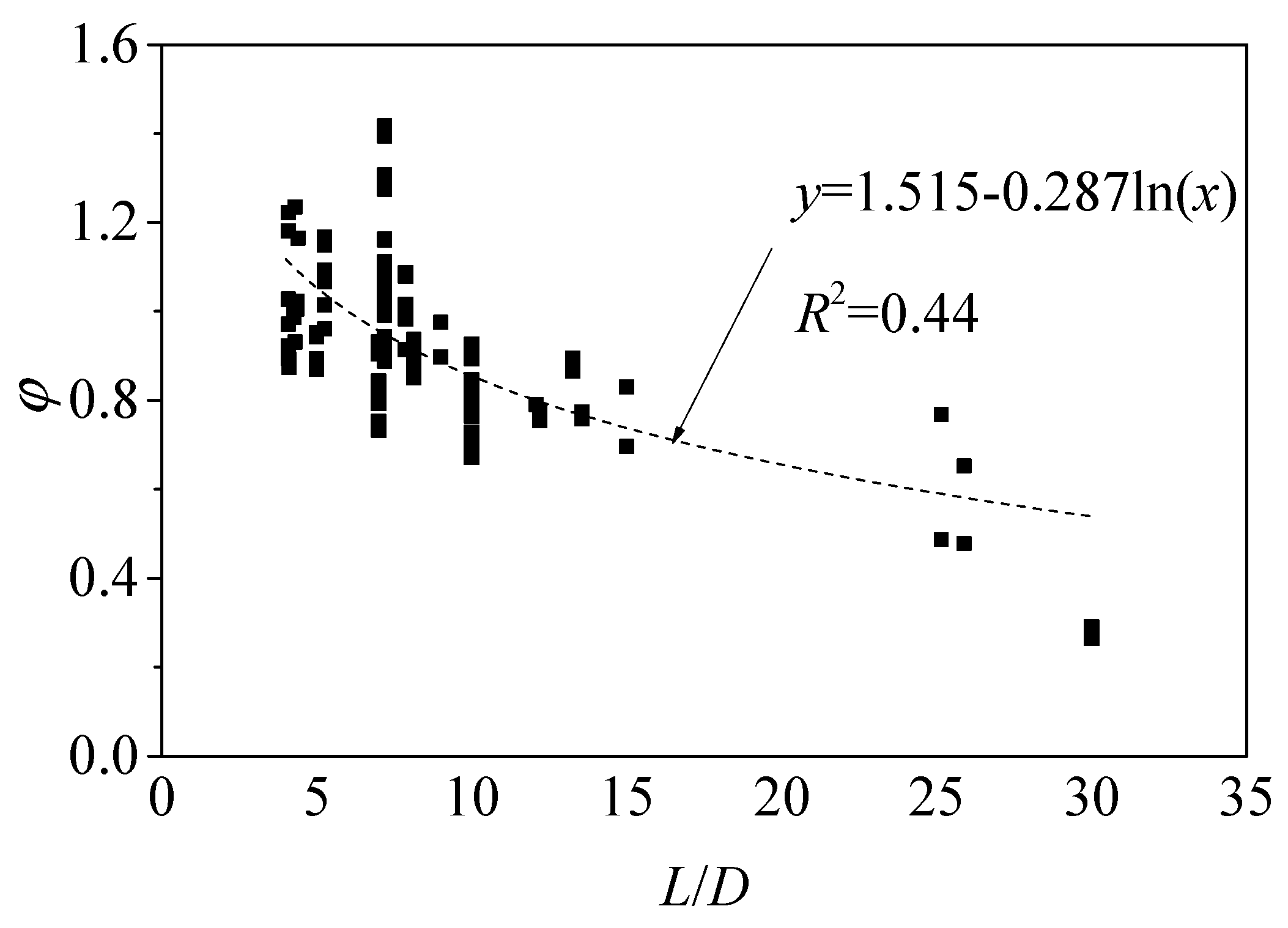
3.4.3. Axial Bearing Capacity Model for CFST Circular Long Columns Nul

Based on the axial bearing capacity model Nus, the axial bearing capacity model for CFST circular long columns Nul can be considered as the strength reduction φ caused by the slenderness ratio. Therefore, the calculation model for CFST circular long columns Nul can be expressed as:
N u l = φ N u s
The existing research results show that there is an obvious nonlinear relationship between φ and the slenderness ratio [64]. Figure 5 shows the relationship between φ and the slenderness ratio L/D. As shown in Figure 5, there is an obvious nonlinear relationship between φ and the slenderness ratio, and φ gradually decreases with the increase in L/D. Based on Equation (27), Equation (28) is obtained by fitting the test results of CFST circular long columns in Table 2, and the correlation coefficient R2 is 0.44.
φ = 1.515 0.287 ln ( L / D )
To sum up, the calculation model Nul can be obtained by Equation (29).
N u l = [ 1.515 0.287 ln ( L / D ) ] { 0.869 A s f s y + [ 0.448 t D 2 t f s y + [ ( 0.1 ( f c ) 0.032 ) 2 1 0.1 ( f c ) 0.032 ] 0.448 t D 2 t f s y f c + ( f c ) 2 ] A c }
Therefore, the proposed model for CFST circular short and long columns is shown in Equations (30) and (31). Equation (30) is a unified model for the axial bearing capacity of CFST circular columns. Equation (31) is used to consider the influence of the slenderness ratio on bearing capacity.
N u s = φ { 0.869 A s f s y + [ 0.448 t D 2 t f s y + [ ( 0.1 ( f c ) 0.032 ) 2 1 0.1 ( f c ) 0.032 ] 0.448 t D 2 t f s y f c + ( f c ) 2 ] A c }
φ = { 1 L / D 4 1.515 0.287 ln ( L / D ) L / D > 4

4. Assessment of Axial Bearing Capacity Model for CFST Circular Columns

To verify the accuracy of the proposed model, two parameters, including the average value (AV) and integral absolute error (IAE), were selected in this paper [70,71], as shown in Equations (32) and (33). When AV and IAE approach 1 and 0, this shows that the predicted value of the proposed model is closer to the experimental value, which further shows that the proposed model is accurate.
A V = 1 n T h e o i E x p e i n
I A E = 1 n | T h e o i E x p e i | 1 n | E x p e i |
where Theoi and Expei represent the predicted value and experimental value of the i-th specimen, respectively, and n represents the number of specimens.

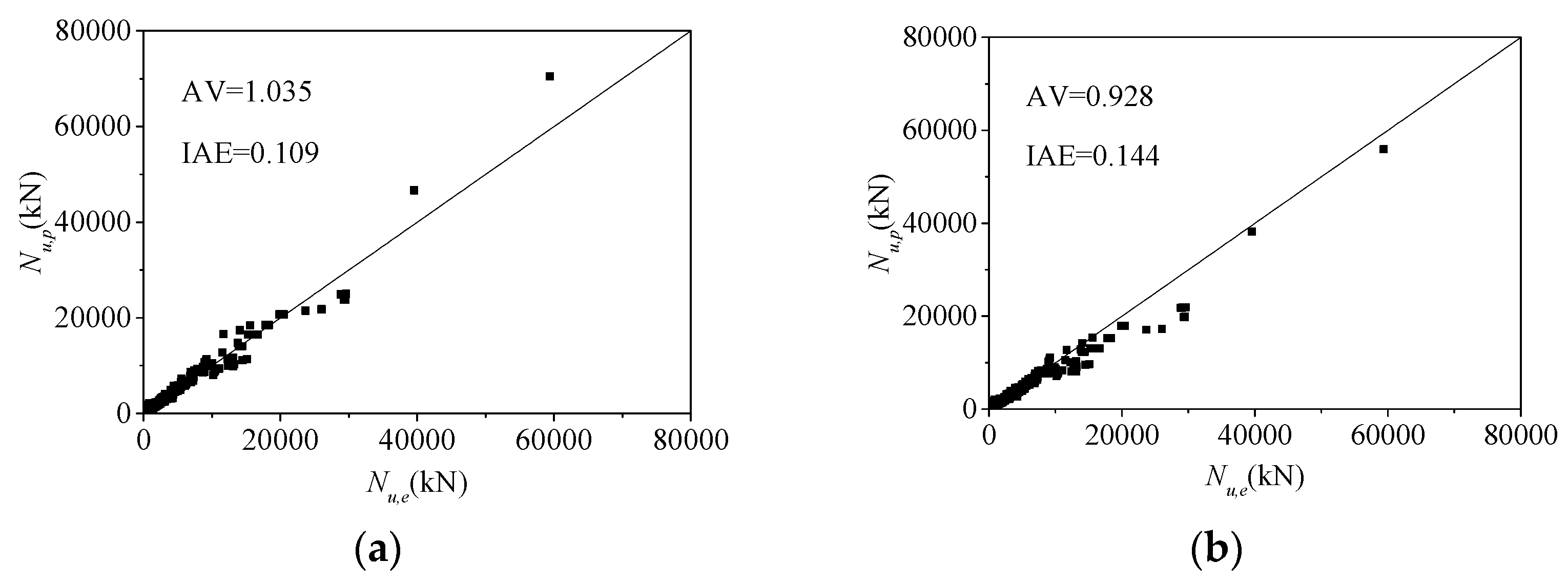
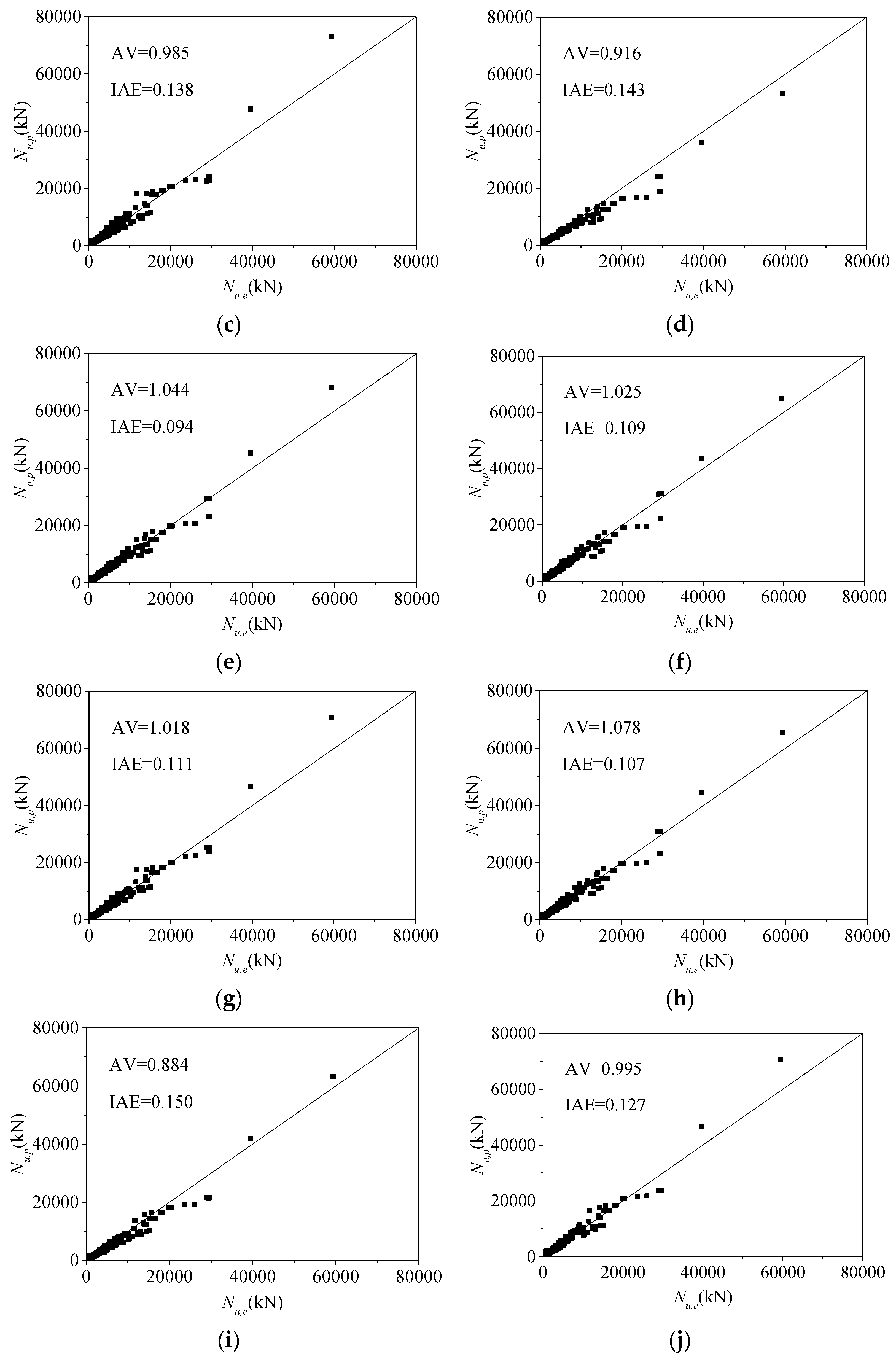
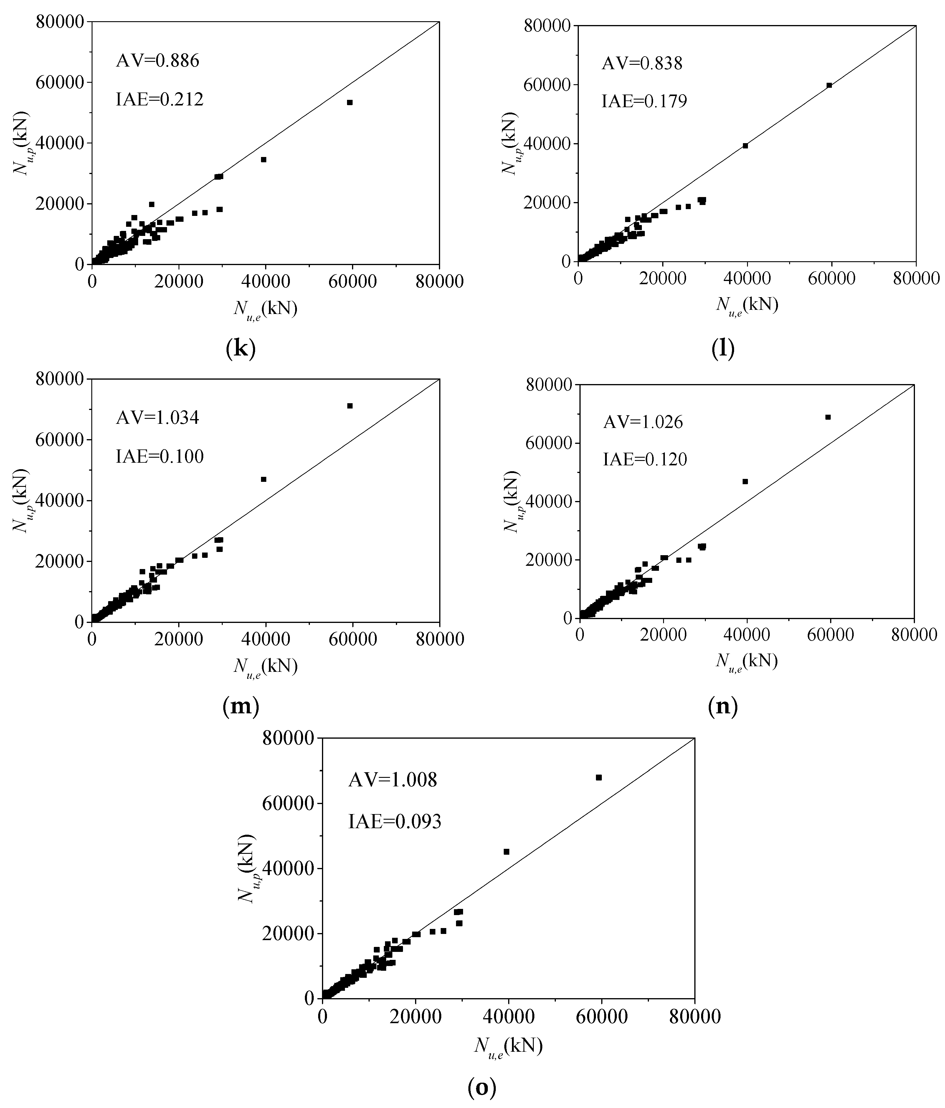
4.1. Assessment of Axial Bearing Capacity Model for CFST Circular Short Columns

By predicting the experimental values in Table 2, the model assessment results are shown in Figure 6, where Nu,e represents the experimental values and Nu,p represents the predicted values. As can be seen from the model assessment results, the AV and IAE of the model proposed in this paper are 1.008 and 0.093, respectively, which are the closest to 1 and 0. This shows that the proposed model is the most accurate, mainly because it is a theoretical model and can be used in a wider range of applications. In addition, Sakino et al.’s model [37] also has high accuracy. It shows that the calculation model for the axial bearing capacity of CFST based on the superposition theory and limit equilibrium theory and stress component of steel tubular based on the von Mises yield criterion is reasonable and reliable. However, the axial bearing capacity model established directly by superposition theory has a large error, as in Oliveira et al. [64]. Therefore, the axial bearing capacity of CFST short columns can be obtained by the proposed model.

4.2. Assessment of Axial Bearing Capacity Model for CFST Circular Long Columns

At present, there are few calculation models for CFST long columns. Therefore, Oliveira et al.’s model [64] was used to calculate the axial bearing capacity of CFST long columns and compare it with the proposed model. Figure 7 shows the assessment results of existing calculation models for CFST long columns. As can be seen from Figure 8, the model proposed in this paper has higher accuracy than Oliveira et al.’s model [64], and AV and IAE are 1.031 and 0.108. Hence, the axial bearing capacity of CFST short columns can be calculated by the proposed model.

4.3. Assessment of Unified Model for CFST Circular Columns

In addition, the proposed model is a unified model, which can calculate the axial bearing capacity of CFST short and long columns. Therefore, the proposed model can be used to predict the axial bearing capacity of CFST short and long columns. As shown in Figure 8, AV and IAE are 1.012 and 0.094, respectively. To sum up, the axial bearing capacity of CFST short and long columns can be determined by the proposed model.

4.4. Prediction of Axial Bearing Capacity of CFST Columns under High Temperature

The concrete core of the CFST columns subjected to high temperature is still under three-dimensional confining pressure under axial load. From this aspect and the theoretical model, it can be concluded that the bearing capacity of the CFST columns subjected to normal temperature can still be applied to the CFST columns subjected to high temperature. The main difference between them is that the material properties of concrete and steel tube will be weakened under the action of high temperature, and the strength of concrete, the elastic model of concrete, the yield strength of steel, and the elastic model of steel are all reduced to varying degrees. Therefore, the reduced strength of materials should be used to consider the influence of high temperature when calculating the bearing capacity of CFST columns under high temperature by using the unified model for bearing capacity in this paper.
At the same time, to prove the universality of the proposed model, the proposed model also was used to evaluate the axial bearing capacity of CFST columns under high temperatures to reflect the accuracy of the proposed model, as shown in Figure 9. The experimental data come from a published reference [72], with 10 specimens in total, which discusses an experimental study of the residual axial bearing capacity of high-strength CFST short columns under axial compression after fire. As shown in Figure 9, the model proposed in this paper also has high accuracy in predicting the axial bearing capacity of CFST columns under high temperatures, and AV and IAE are 1.007 and 0.100. On the other hand, it also shows that the confinement mechanism established in this paper is correct. In other words, it is accurate to use the Hoek–Brown failure criterion to calculate ultimate compressive strength.

5. Conclusions

To overcome the limitations of existing axial bearing capacity models, the proposed model for CFST columns under axial compression was established by the Hoek–Brown failure criterion in this paper. To verify the accuracy of the models, 798 experiments were collected to evaluate the accuracy of existing published models and the proposed model. The following conclusions can be obtained:
(1)
Most of the existing models are empirical models. On the one hand, there are some limitations in the application of the models. On the other hand, the types of experimental data and the parameter range affect the accuracy of the published models.
(2)
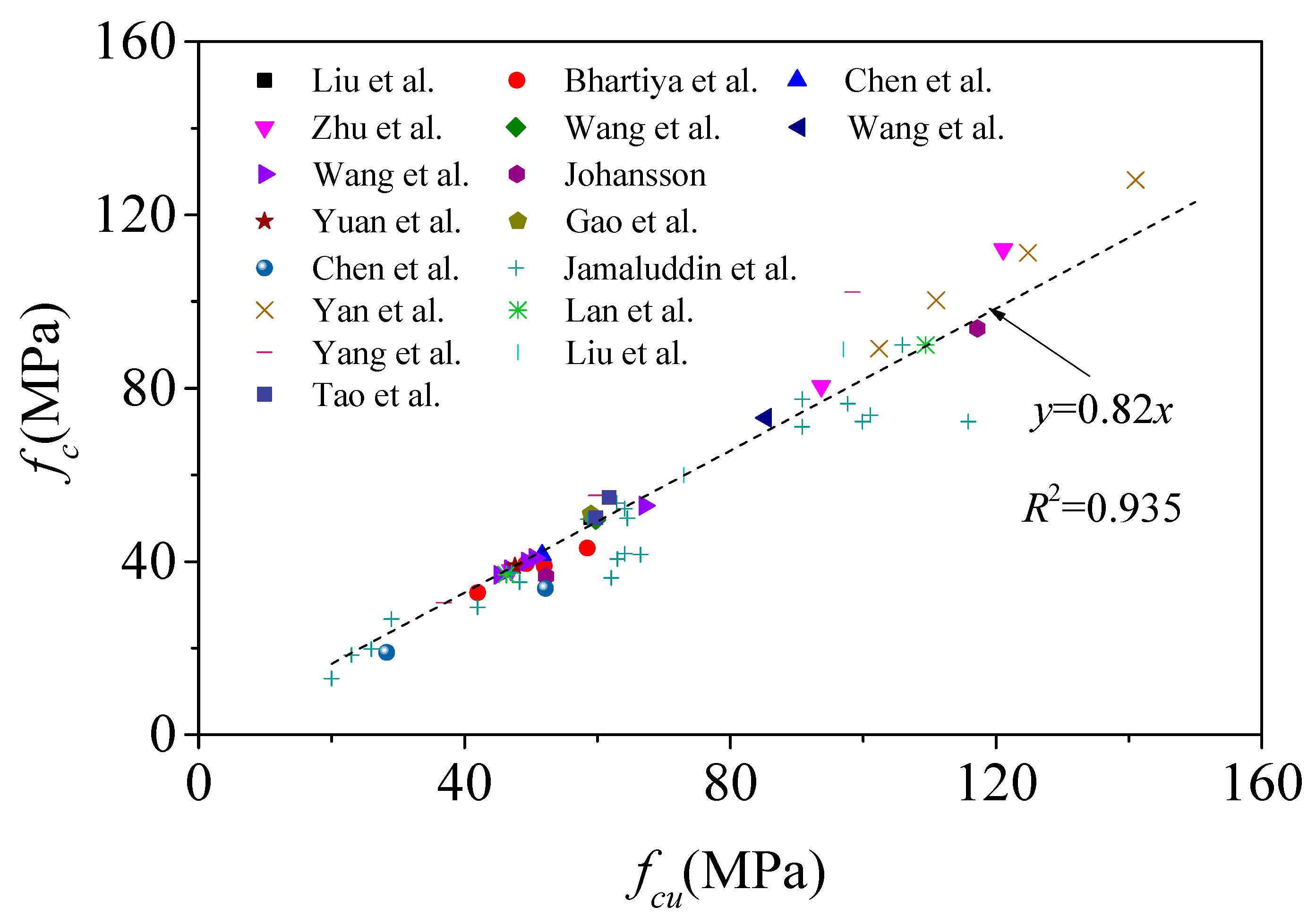
There is a linear relationship between cylinder and cube compressive strength, and the ratio is approximately 0.82.
(3)
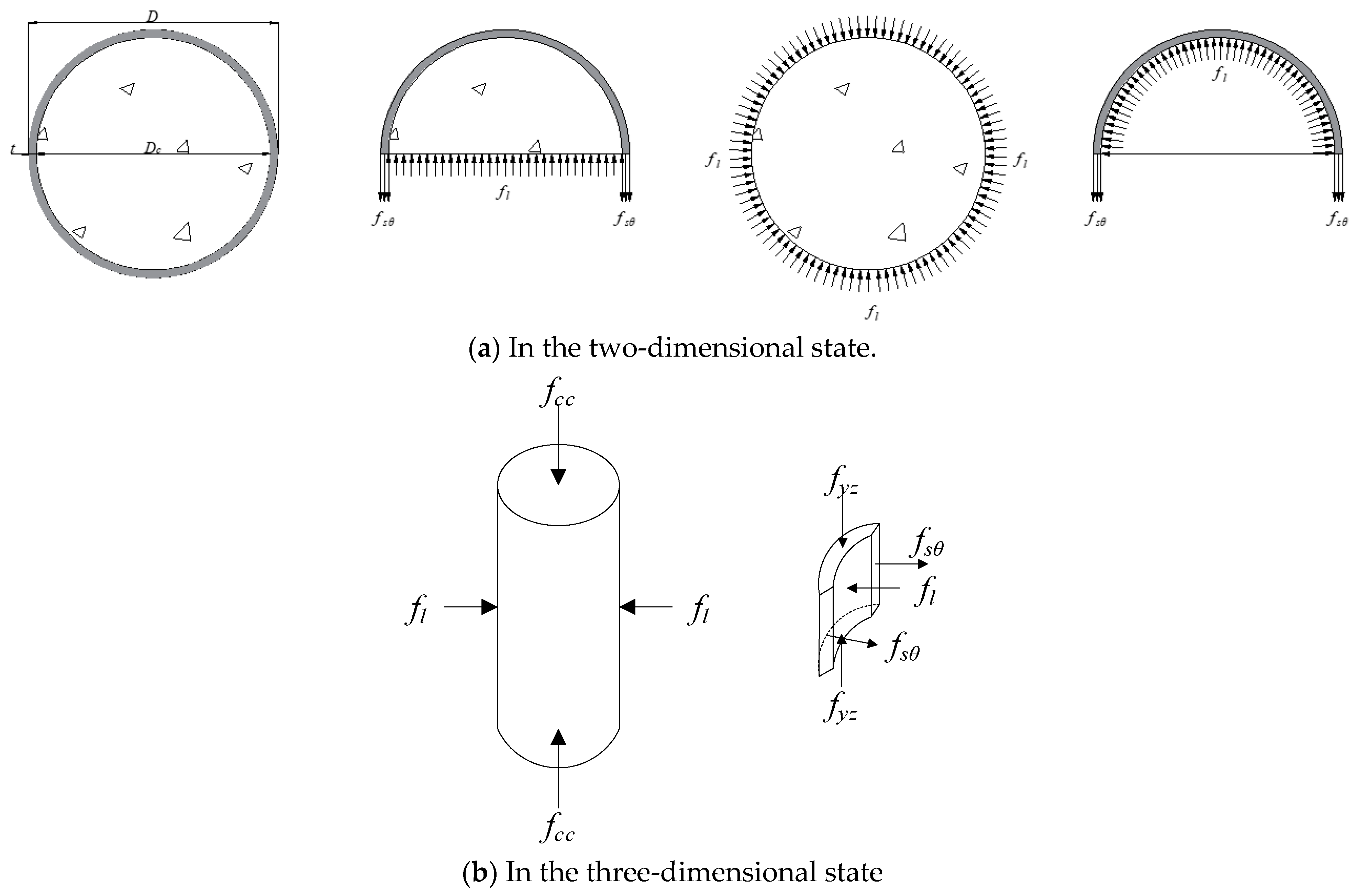
The ultimate compressive strength was established by the Hoek–Brown failure criterion, considering the section size, diameter–thickness ratio, and concrete strength. At the same time, the vertical and transverse stress components of steel tubular are determined by the von Mises yield criterion. Therefore, from this point of view, the steel corresponding to the ultimate compressive strength may not reach the yield strength.
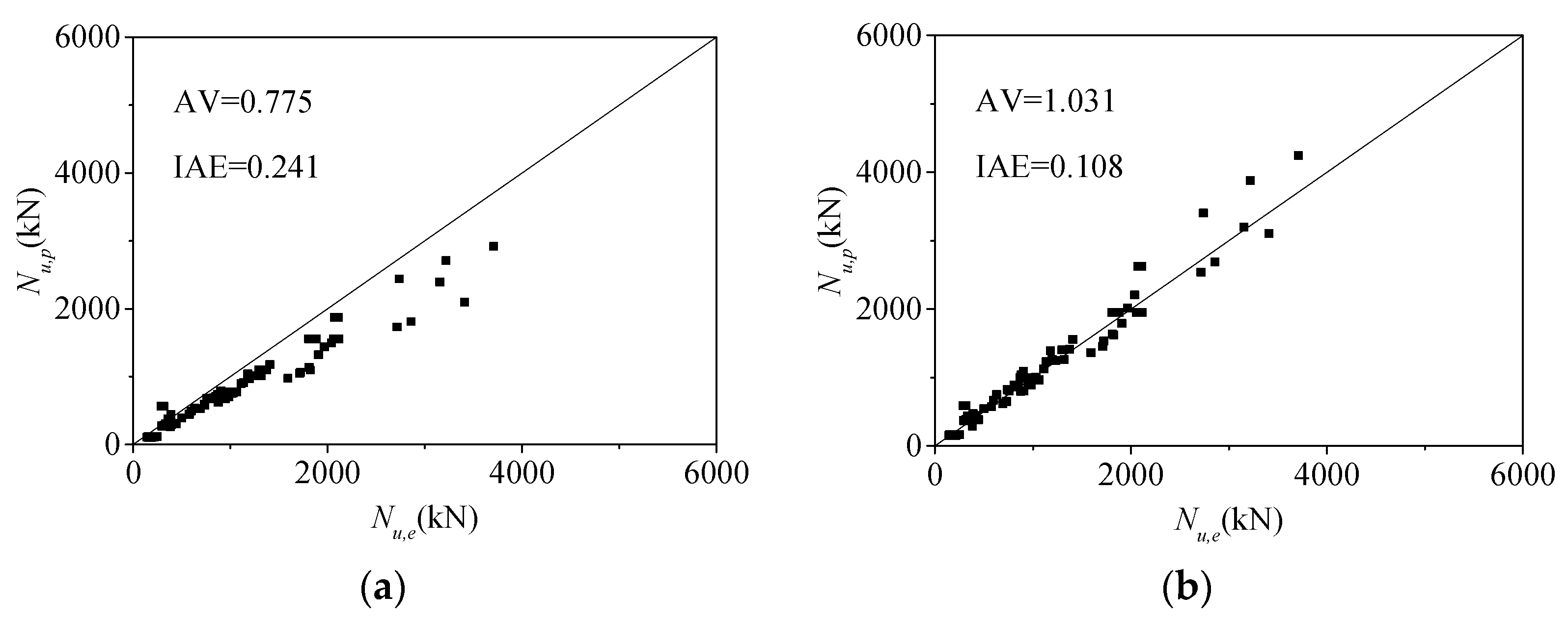
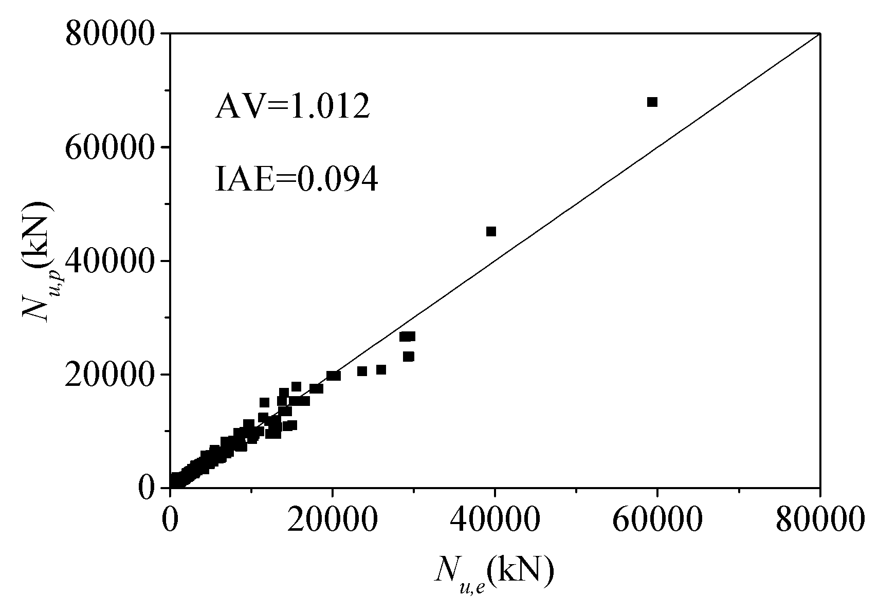
(4)
Based on the ultimate compressive strength established by the Hoek–Brown failure criterion, the axial bearing capacity model for CFST short columns can accurately predict 681 test data, and AV and IAE are 1.008 and 0.093, compared with other existing models. It also fully shows that it is reasonable based on superposition theory and limit equilibrium theory. At the same time, the axial bearing capacity model can accurately predict the data of 107 CFST long columns, and AV and IAE are 1.031 and 0.108. The axial bearing capacity for CFST short and long columns can be predicted at the same time since the proposed model is a unified model. The prediction results of the proposed unified model are 1.012 and 0.094, respectively, which shows that the proposed model is accurate.
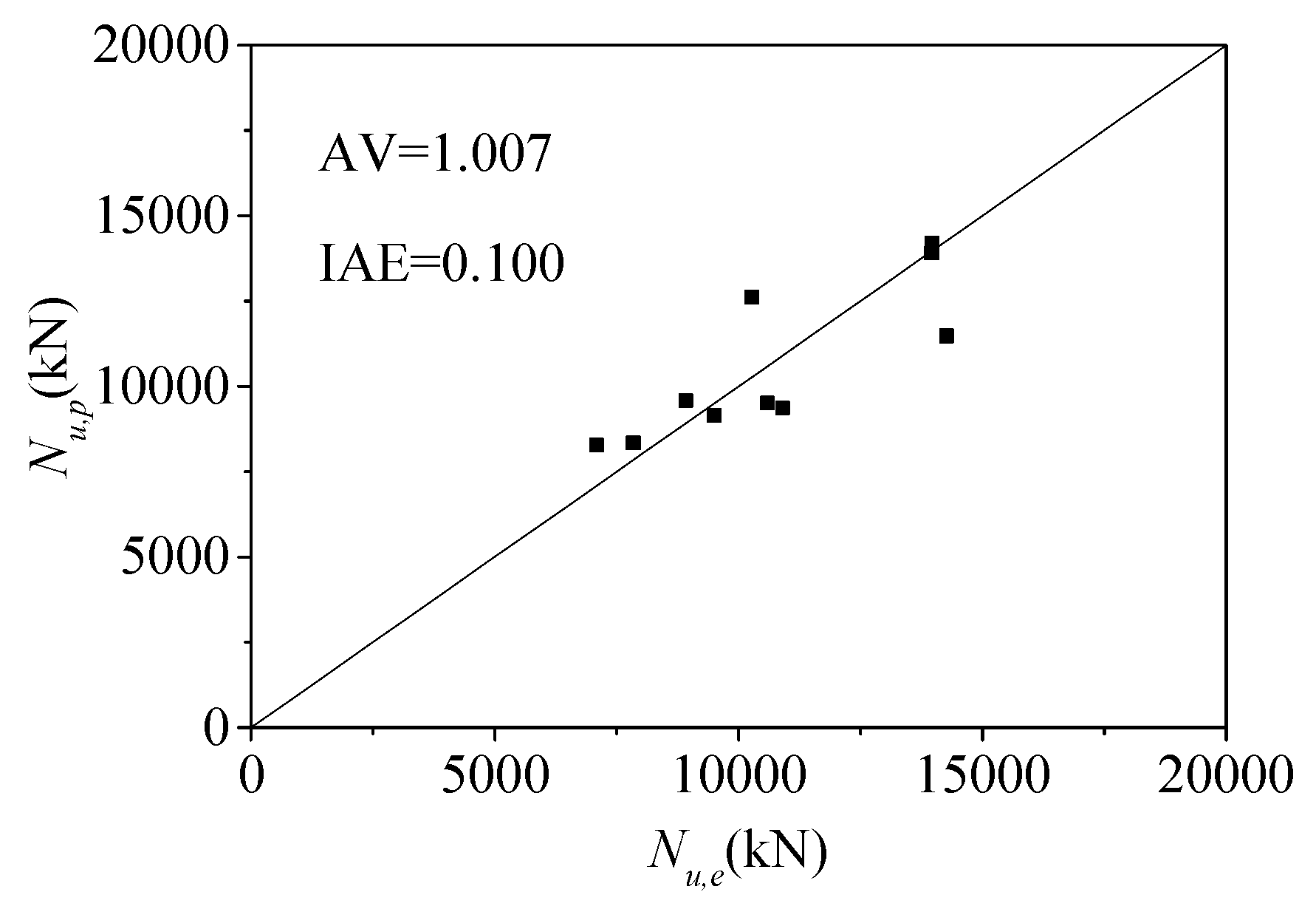
(5)
The proposed model also predicts the axial bearing capacity of CFST columns under high temperatures, and the AV and IAE are 1.007 and 0.100. On the one hand, it shows that the proposed model can be used to predict the axial bearing capacity of CFST columns under high temperatures. On the other hand, it also shows that the establishment process and confinement mechanism of the proposed model are correct and reasonable.
(6)
From the assessment results of the models, the calculation model for axial bearing capacity established by the superposition theory and limit equilibrium theory and the stress component of steel tube based on von Mises yield criterion is reasonable and reliable.

Funding

This research received no external funding.

Data Availability Statement

The original data will be available upon requirement.

Conflicts of Interest

The authors declare no conflict of interest.

References

  1. Zhou, S.; Sun, Q.; Wu, X. Impact of D/t ratio on circular concrete-filled high-strength steel tubular stub columns under axial compression. Thin Walled Struct. 2018, 132, 461–474. [Google Scholar] [CrossRef]
  2. Hasan, H.G.; Ekmekyapar, T. Bond-slip behaviour of concrete filled double skin steel tubular (CFDST) columns. Mar. Struct. 2021, 79, 103061. [Google Scholar] [CrossRef]
  3. Liu, J.; Gao, P.; Lin, X.; Wang, X.; Zhou, X.; Chen, Y.F. Experimental assessment on the size effects of circular concrete-filled steel tubular columns under axial compression. Eng. Struct. 2023, 275, 115247. [Google Scholar] [CrossRef]
  4. Azevedo, V.d.S.d.; Lima, L.R.O.d.; Vellasco, P.C.G.d.S.; Tavares, M.E.d.N.; Chan, T.M. Experimental investigation on recycled aggregate concrete filled steel tubular stub columns under axial compression. J. Constr. Steel Res. 2021, 187, 106930. [Google Scholar] [CrossRef]
  5. Lyu, W.Q.; Han, L.H.; Hou, C. Axial compressive behaviour and design calculations on recycled aggregate concrete-filled steel tubular (RAC-FST) stub columns. Eng. Struct. 2021, 241, 112452. [Google Scholar] [CrossRef]
  6. Wang, Y.; Chen, J.; Geng, Y. Testing and analysis of axially loaded normal-strength recycled aggregate concrete filled steel tubular stub columns. Eng. Struct. 2015, 86, 192–212. [Google Scholar] [CrossRef]
  7. Guler, S.; Aydogan, M.; Çopur, A. Axial capacity and ductility of circular UHPC-filled steel tube columns. Mag. Concr. Res. 2013, 65, 898–905. [Google Scholar] [CrossRef]
  8. Chen, S.; Zhang, R.; Jia, L.J.; Wang, J.Y.; Gu, P. Structural behavior of UHPC filled steel tube columns under axial loading. Thin Walled Struct. 2018, 130, 550–563. [Google Scholar] [CrossRef]
  9. Yan, Y.; Xu, L.; Li, B.; Chi, Y.; Yu, M.; Zhou, K.; Song, Y. Axial behavior of ultra-high performance concrete (UHPC) filled stocky steel tubes with square sections. J. Constr. Steel Res. 2019, 158, 417–428. [Google Scholar] [CrossRef]
  10. Yang, Y.F.; Ma, G.L. Experimental behaviour of recycled aggregate concrete filled stainless steel tube stub columns and beams. Thin Walled Struct. 2013, 66, 62–75. [Google Scholar] [CrossRef]
  11. Yu, Q.; Tao, Z.; Wu, Y.X. Experimental behaviour of high performance concrete-filled steel tubular columns. Thin Walled Struct. 2008, 46, 362–370. [Google Scholar] [CrossRef]
  12. Wei, J.; Xie, Z.; Zhang, W.; Lou, X.; Yang, Y.; Chen, B. Experimental study on circular steel tube-confined reinforced UHPC columns under axial loading. Eng. Struct. 2021, 230, 111599. [Google Scholar] [CrossRef]
  13. Su, M.; Cai, Y.; Chen, X.; Young, B. Behaviour of concrete-filled cold-formed high strength steel circular stub columns. Thin Walled Struct. 2020, 157, 107078. [Google Scholar] [CrossRef]
  14. Liew, J.Y.R.; Xiong, M.; Xiong, D. Design of concrete filled tubular beam-columns with high strength steel and concrete. Structures 2016, 8, 213–226. [Google Scholar] [CrossRef]
  15. Uy, B.; Tao, Z.; Han, L.H. Behaviour of short and slender concrete-filled stainless steel tubular columns. J. Constr. Steel Res. 2011, 67, 360–378. [Google Scholar] [CrossRef]
  16. Oliveira, W.L.A.d.; Nardin, S.D.; Debs, A.L.H.d.C.E.; Debs, M.K.E. Influence of concrete strength and length/diameter on the axial capacity of CFT columns. J. Constr. Steel Res. 2009, 65, 2103–2110. [Google Scholar] [CrossRef]
  17. Bhartiya, R.; Oinamb, R.M.; Sahoo, D.R.; Utkarsh, K. Modified confinement model for monotonic axial behavior of concrete-filled tubular columns. J. Constr. Steel Res. 2021, 180, 106570. [Google Scholar] [CrossRef]
  18. GB 50936-2014; Technical Code for Concrete-Filled Steel Tubular Structures. Ministry of Housing and Urban-Rural Development of the People’s Republic of China: Beijing, China, 2014. (In Chinese)
  19. Chen, J.; Wang, Y.; Roeder, C.W.; Ma, J. Behavior of normal-strength recycled aggregate concrete filled steel tubes under combined loading. Eng. Struct. 2017, 130, 23–40. [Google Scholar] [CrossRef]
  20. Zhu, J.Y.; Chan, T.M. Experimental investigation on octagonal concrete filled steel stub columns under uniaxial compression. J. Constr. Steel Res. 2018, 147, 457–467. [Google Scholar] [CrossRef]
  21. Wang, W.; Ma, H.; Li, Z.; Tang, Z. Size effect in circular concrete-filled steel tubes with different diameter-to-thickness ratios under axial compression. Eng. Struct. 2017, 151, 554–567. [Google Scholar] [CrossRef]
  22. Wang, Y.; Chen, P.; Liua, C.; Zhang, Y. Size effect of circular concrete-filled steel tubular short columns subjected to axial compression. Thin Walled Struct. 2017, 120, 397–407. [Google Scholar] [CrossRef]
  23. Johansson, M. The efficiency of passive confinement in CFT columns. Steel Compos. Struct. 2002, 2, 379–396. [Google Scholar] [CrossRef]
  24. Yuan, F.; Cao, L.; Li, H. Axial compressive behaviour of high-strength steel spiral-confined square concrete-filled steel tubular columns. J. Constr. Steel Res. 2022, 192, 107245. [Google Scholar] [CrossRef]
  25. Gao, P.; Zhou, X.; Liu, J.; Lin, X.; Wang, X.; Chen, Y.F. Experimental assessment on the size effects of square concrete-filled steel tubular columns under axial compression. Eng. Struct. 2023, 281, 115706. [Google Scholar] [CrossRef]
  26. Chen, Z.; Zhou, J.; Jing, C.; Tan, Q. Mechanical behavior of spiral stirrup reinforced concrete filled square steel tubular columns under compression. Eng. Struct. 2021, 226, 111377. [Google Scholar] [CrossRef]
  27. Jamaluddin, N.; Lam, D.; Dai, X.H.; Ye, J. An experimental study on elliptical concrete filled columns under axial compression. J. Constr. Steel Res. 2013, 87, 6–16. [Google Scholar] [CrossRef]
  28. Lam, D.; Gardner, L.; Burdett, M. Behaviour of axially loaded concrete filled stainless steel elliptical stub columns. Adv. Struct. Eng. 2010, 13, 493–500. [Google Scholar] [CrossRef]
  29. Yang, H.; Lam, D.; Gardner, L. Testing and analysis of concrete-filled elliptical hollow sections. Eng. Struct. 2008, 30, 3771–3781. [Google Scholar] [CrossRef]
  30. Liu, D. Tests on high-strength rectangular concrete-filled steel hollow section stub columns. J. Constr. Steel Res. 2005, 61, 902–911. [Google Scholar] [CrossRef]
  31. Tao, Z.; Han, L.H.; Wang, Z.B. Experimental behaviour of stiffened concrete-filled thin-walled hollow steel structural (HSS) stub columns. J. Constr. Steel Res. 2005, 61, 962–983. [Google Scholar] [CrossRef]
  32. Ding, F.X.; Zhua, J.; Cheng, S.; Liu, X. Comparative study of stirrup-confined circular concrete-filled steel tubular stub columns under axial loading. Thin Walled Struct. 2018, 123, 294–304. [Google Scholar] [CrossRef]
  33. Guler, S.; Çopur, A.; Aydogan, M. A comparative study on square and circular high strength concrete-filled steel tube columns. Adv. Steel Constr. 2014, 10, 234–247. [Google Scholar]
  34. Giakoumelis, G.; Lam, D. Axial capacity of circular concrete-filled tube columns. J. Constr. Steel Res. 2004, 60, 1049–1068. [Google Scholar]
  35. Xiong, M.X.; Xiong, D.X.; Liew, J.Y.R. Axial performance of short concrete filled steel tubes with high- and ultra-high- strength materials. Eng. Struct. 2017, 136, 494–510. [Google Scholar] [CrossRef]
  36. Schneider, S.P. Axially loaded concrete-filled steel tubes. J. Struct. Eng. 1998, 124, 1125–1138. [Google Scholar] [CrossRef]
  37. Sakino, K.; Nakahara, H.; Morino, S.; Nishiyama, I. Behavior of centrally loaded concrete-filled steel-tube short columns. J. Struct. Eng. 2004, 130, 180–188. [Google Scholar] [CrossRef]
  38. Lu, Y.; Li, N.; Li, S.; Liang, H. Behavior of steel fiber reinforced concrete-filled steel tube columns under axial compression. Constr. Build. Mater. 2015, 95, 74–85. [Google Scholar] [CrossRef]
  39. Tam, V.W.Y.; Wang, Z.B.; Tao, Z. Behaviour of recycled aggregate concrete filled stainless steel stub columns. Mater. Struct. 2014, 47, 293–310. [Google Scholar] [CrossRef]
  40. Cai, Y.; Kwan, A.K.H.; Li, L.G. Circular concrete filled steel tubes made of eco-concrete with limestone fines added as cementitious paste replacement. Structures 2020, 28, 69–79. [Google Scholar] [CrossRef]
  41. Dai, P.; Yang, L.; Wang, J.; Zhou, Y. Compressive strength of concrete-filled stainless steel tube stub columns. Eng. Struct. 2020, 205, 110106. [Google Scholar] [CrossRef]
  42. O’Shea, M.D.; Bridge, R.Q. Design of circular thin-walled concrete filled steel tubes. J. Struct. Eng. 2000, 126, 1295–1303. [Google Scholar] [CrossRef]
  43. Yang, Y.F.; Han, L.H. Compressive and flexural behaviour of recycled aggregate concrete filled steel tubes (RACFST) under short-term loadings. Steel Compos. Struct. 2006, 6, 257–284. [Google Scholar] [CrossRef]
  44. Han, L.H.; Yao, G.H. Experimental behaviour of thin-walled hollow structural steel (HSS) columns filled with self-consolidating concrete (SCC). Thin Walled Struct. 2004, 42, 1357–1377. [Google Scholar] [CrossRef]
  45. Gupta, P.K.; Sarda, S.M.; Kumar, M.S. Experimental and computational study of concrete filled steel tubular columns under axial loads. J. Constr. Steel Res. 2007, 63, 182–193. [Google Scholar] [CrossRef]
  46. Abed, F.; AlHamaydeh, M.; Abdalla, S. Experimental and numerical investigations of the compressive behavior of concrete filled steel tubes (CFSTs). J. Constr. Steel Res. 2013, 80, 429–439. [Google Scholar] [CrossRef]
  47. Yu, Z.W.; Ding, F.X.; Cai, C.S. Experimental behavior of circular concrete-filled steel tube stub columns. J. Constr. Steel Res. 2007, 63, 165–174. [Google Scholar] [CrossRef]
  48. Ekmekyapar, T.; Al-Eliwi, B.J.M. Experimental behaviour of circular concrete filled steel tube columns and design specifications. Thin Walled Struct. 2016, 105, 220–230. [Google Scholar] [CrossRef]
  49. Chan, T.M.; Huai, Y.M.; Wang, W. Experimental investigation on lightweight concrete-filled cold-formed elliptical hollow section stub columns. J. Constr. Steel Res. 2015, 115, 434–444. [Google Scholar] [CrossRef]
  50. Xue, J.Q.; Briseghella, B.; Chen, B.C. Effects of debonding on circular CFST stub columns. J. Constr. Steel Res. 2012, 69, 64–76. [Google Scholar] [CrossRef]
  51. Zhu, L.; Ma, L.; Bai, Y.; Li, S.; Song, Q.; Wei, Y.; Zhang, L.; Zhang, Z.; Sha, X. Large diameter concrete-filled high strength steel tubular stub columns under compression. Thin Walled Struct. 2016, 108, 12–19. [Google Scholar] [CrossRef]
  52. Ding, F.X.; Liu, J.; Liu, X.M.; Yu, Z.W.; Li, D.W. Mechanical behavior of circular and square concrete filled steel tube stub columns under local compression. Thin Walled Struct. 2015, 94, 155–166. [Google Scholar] [CrossRef]
  53. Xiao, J.; Huang, Y.; Yang, J.; Zhang, C. Mechanical properties of confined recycled aggregate concrete under axial compression. Constr. Build. Mater. 2012, 26, 591–603. [Google Scholar] [CrossRef]
  54. Wan, C.Y.; Zha, X.X. Nonlinear analysis and design of concrete-filled dual steel tubular columns under axial loading. Steel Compos. Struct. 2016, 20, 571–597. [Google Scholar] [CrossRef]
  55. Hu, H.S.; Lin, K.; Shahrooz, B.M.; Guo, Z.X. Revisiting the composite action in axially loaded circular CFST columns through direct measurement of load components. Eng. Struct. 2021, 235, 112066. [Google Scholar] [CrossRef]
  56. Han, L.H.; Yao, G.H.; Zhao, X.L. Tests and calculations for hollow structural steel (HSS) stub columns filled with self-consolidating concrete (SCC). J. Constr. Steel Res. 2005, 61, 1241–1269. [Google Scholar] [CrossRef]
  57. Chang, Y.; Chen, W.; Xiao, Q.; Rong, E.; Peng, L. Theoretical and experimental study on axial compression concrete-filled tubes with different confinements. J. Constr. Steel Res. 2021, 185, 106862. [Google Scholar] [CrossRef]
  58. Lai, M.H.; Ho, J.C.M. A theoretical axial stress-strain model for circular concrete-filled-steel-tube columns. Eng. Struct. 2016, 125, 124–143. [Google Scholar] [CrossRef]
  59. Huang, C.S.; Yeh, Y.K.; Liu, G.Y.; Hu, H.T.; Tsai, K.C.; Weng, Y.T.; Wang, S.H.; Wu, M.H. Axial load behavior of stiffened concrete-filled steel columns. J. Struct. Eng. 2002, 128, 1222–1230. [Google Scholar] [CrossRef]
  60. Liao, F.Y.; Han, L.H.; He, S.H. Behavior of CFST short column and beam with initial concrete imperfection: Experiments. J. Constr. Steel Res. 2011, 67, 1922–1935. [Google Scholar] [CrossRef]
  61. Hu, Y.M.; Yu, T.; Teng, J.G. FRP-confined circular concrete-filled thin steel tubes under axial compression. J. Compos. Constr. 2011, 15, 850–860. [Google Scholar] [CrossRef]
  62. Duarte, A.P.C.; Silva, B.A.; Silvestre, N.; Brito, J.D.; Júlio, E.; Castro, J.M. Tests and design of short steel tubes filled with rubberised concrete. Eng. Struct. 2016, 112, 274–286. [Google Scholar] [CrossRef]
  63. Han, L.H. Concrete Filled Steel Tubular Structures-Theory and Practice; Science Press: Beijing, China, 2016. [Google Scholar]
  64. Oliveira, W.L.A.d.; Nardin, S.D.; Debsa, A.L.H.d.C.E.; Debs, M.K.E. Evaluation of passive confinement in CFT columns. J. Constr. Steel Res. 2010, 66, 487–495. [Google Scholar] [CrossRef]
  65. Yu, Q.; Tao, Z.; Liu, W.; Chen, Z.B. Analysis and calculations of steel tube confined concrete (STCC) stub columns. J. Constr. Steel Res. 2010, 66, 53–64. [Google Scholar] [CrossRef]
  66. Lai, Z.; Jiang, H.; Cai, Y. A new design equation to estimate the axial compressive strength of circular concrete-filled steel tubular stub columns. Structures 2022, 46, 1043–1054. [Google Scholar] [CrossRef]
  67. Hoek, E.; Brown, E.T. Underground Excavations in Rock; Institution of Mining and Metallurgy: London, UK, 1980; pp. 510–530. [Google Scholar]
  68. Hoek, E. The Hoek-Brown failure criterion-a 1988 update. In Proceedings of the 15th Canadian Rock Mechanics Symposium; Department Civil Engineering, University of Toronto: Toronto, ON, Canada, 1988; pp. 31–38. [Google Scholar]
  69. Hoek, E.; Carranza-Torres, C.; Corkum, B. Hoek-Brown failure criterion-2002 edition. In Proceedings of the Fifth North American Rock Mechanics Symposium (NARMS-TAC), Toronto, ON, Canada, 7–10 July 2002; University of Toronto Press: Toronto, ON, Canada, 2002; pp. 267–273. [Google Scholar]
  70. Wu, Y.F.; Zhou, Y.W. Unified strength model based on Hoek-Brown failure criterion for circular and square concrete columns confined by FRP. J. Compos. Constr. 2010, 14, 175–184. [Google Scholar] [CrossRef]
  71. Zhang, Y.; Lu, Z.F.; Cao, Y.G. Unified strength model based on the Hoek-Brown failure criterion for fibre-reinforced polymer-confined pre-damaged concrete columns with circular and square cross sections. J. Cent. South Univ. 2020, 27, 3807–3820. [Google Scholar] [CrossRef]
  72. Lyu, X. Residual Load Capacity and Experimental Research on Short Steel Tube Infilled with High Strength Concrete Column Post-Fire; Southeast University: Nanjing, China, 2018. (In Chinese) [Google Scholar]
Figure 1. Concrete-filled steel tubular column.
Buildings 13 02408 g001
Figure 2. The content and parameters considered.
Buildings 13 02408 g002
Figure 3. Stress state of CFST columns, steel tubular, and core concrete.
Buildings 13 02408 g003
Figure 4. Relationship between cube and cylinder compressive strength [3,6,9,17,19,20,21,22,23,24,25,26,27,28,29,30,31].
Buildings 13 02408 g004
Figure 5. Relationship between strength reduction coefficient and slenderness ratio.
Buildings 13 02408 g005
Figure 6. Assessment results of existing calculation models of CFST short columns. (a) Han’s model [63]. (b) Liu et al.’s model [3]. (c) Giakoumelis et al.’s model [34]. (d) Sakino et al.’s model [37]. (e) Lu et al.’s model [38]. (f) Xiao et al.’s model [53]. (g) Hu et al.’s model [55]. (h) Wang et al.’s model [22]. (i) Chen et al.’s model [8]. (j) Han et al.’s model [56]. (k) Chang et al.’s model [57]. (l) Oliveirs et al.’s model [64]. (m) Yu et al.’s model [65]. (n) Lai et al.’s model [66]. (o) The proposed model.
Buildings 13 02408 g006aBuildings 13 02408 g006bBuildings 13 02408 g006c
Figure 7. Assessment results of axial bearing capacity models for CFST long columns. (a) Oliveirs et al.’s model [64]. (b) The proposed model.
Buildings 13 02408 g007
Figure 8. Assessment results of axial bearing capacity models for CFST short and long columns.
Buildings 13 02408 g008
Figure 9. Prediction of axial bearing capacity of CFST columns under high temperature.
Buildings 13 02408 g009
Table 3. Existing axial bearing capacity models.
ReferencesModelsComments
Han [63] N u = ( 1.14 + 1.02 ξ ) f c k A s c      ξ = A s f s y A c f c k      A s c = A s + A c fck: characteristic value of compressive strength
ξ: confinement index
Liu et al. [3] N u = A s f s y + λ c A c f c      λ c = 1.5 ( D 2 t ) ( 6.7 t / D 1.1 ) Ditto
Giakoumelis et al. [34] N u = A s f s y + 1.3 A c f c Ditto
Sakino et al. [37] N u = A s f s z + A c f c c B      f s z = β u c f s y      f c c B = γ U f c + k f r
γ U = 1.67 D c 0.112      f r = 2 t D 2 t f s θ      f s θ = α u f s y
λ = β u c 1 ( D 2 t ) 2 ( D t ) k α u      ( α u ) 2 α u β u c + ( β u c ) 2 = 1
Dc: diameter of the core concrete column
k = 4.1,
λ = 0.27.
Lu et al. [38] N u = A c f c [ 1 + ( 1.55 + 7 V f + 1000 V f 2 ) ξ ]      ξ = A s f s y A c f c Vf: volume percentage of steel fiber
Xiao et al. [53] N u = φ A c f c ( 1 + 1.93 ξ )      φ = 0.88 0.3 r 2 + 0.45 r + 1      ξ = A s f s y A c f c Ditto
Hu et al. [55] N u = f c u A c + 1.15 t D 2 t f s y A c + 0.92 f s y A s Ditto
Wang et al. [22] N u = η a A s f s y + γ u A c f c ( 1 + η c t D f s y γ u f c )
γ u = ( D c 150 ) 0.112 ( 1600 α )      α = 4 ( D / t 1 ) ( D / t 2 ) 2
Ditto
Chen et al. [8] N u = f s y A s + ( 1 + k ) f c A c      k = 0.17 0.0013 D / t f s y / 235 Ditto
Han et al. [56] N u = A s c f s c y      f s c y = ( 1.14 + 1.02 ξ ) f c k      ξ = A s f s y A c f c k Ditto
Chang et al. [57] N u = λ 1 f s y A s + E c E s λ 2 f s y A c Ditto
Oliveira et al. [64] N u = ( f c A c + f s y A s ) λ O l i v e i r a
λ O l i v e i r a = { 1 L / D 3 0.18 ln ( L D ) + 1.2 L / D > 3
Ditto
Yu et al. [65] N u = ( 1.14 + 1.34 ξ ) f c k A c      ξ = A s f s y A c f c k Ditto
Lai et al. [66] N u = { 2.66 ξ 0.5 ( f s y A s ) 0.05 < ξ 7.0 11.9 ( f s y A s ) 0 < ξ 0.05          ξ = A s f s y A c f c Ditto
Note: other parameters (such as α1, η) refer to the original references.
Disclaimer/Publisher’s Note: The statements, opinions and data contained in all publications are solely those of the individual author(s) and contributor(s) and not of MDPI and/or the editor(s). MDPI and/or the editor(s) disclaim responsibility for any injury to people or property resulting from any ideas, methods, instructions or products referred to in the content.

