1. Introduction
In line with the accelerating pace of civil engineering construction in China, there has been a severe shortage of building materials, particularly concrete. However, the amount of waste concrete produced by the demolition of old structures is growing and causing serious pollution to the environment. Recycled concrete is increasingly being used in practical engineering because it can simultaneously alleviate the shortage of building materials and the environmental pollution [
1,
2,
3,
4]. Moreover, earthquakes frequently strike many areas of China. Load-bearing members such as columns are highly susceptible to seismic damage during their service life. The repair and strengthening of seismically damaged columns needs to be thoroughly studied if the columns are made of recycled concrete. At present, external clad steel strengthening, increased section method strengthening, and carbon fiber composite materials (CFRP) strengthening are the main methods of strengthening seismically damaged members [
5,
6,
7,
8]. Among them, CFRP strengthening has been widely used because of its high strength, light weight, good durability, and easy construction [
9,
10,
11,
12,
13,
14]. The CFRP can be used to strengthen columns with or without damages.
Zhou et al. [
15] used CFRP to strengthen non-destructive columns. The results showed that the number of strengthening layers, strengthening height, and strengthening location of CFRP had significant effects on the seismic performance of the specimens. The seismic performance of the columns increased with the increase in the number of strengthening layers and height. Ma and Wu et al. [
16] investigated the axial compression behavior of CFRP-strengthened steel recycled concrete column specimens. It was found that the axial bearing capacity of the specimens decreased with the increase in the recycled aggregate replacement rate and length-to-fine ratio. CFRP effectively improved the axial bearing capacity and deformation capacity of the columns. Ozcan et al. [
17] analyzed the effect of axial load and CFRP fillet radius on the strengthening effect of RC columns through experiments. The results showed that CFRP effectively improved the ductility, energy dissipation capacity, and shear resistance of the specimens.
For the seismic damaged columns strengthened with CFRP, the studies of Yang, Lavorato, and Jin et al. [
18,
19,
20,
21,
22] demonstrated that transversely wound CFRP effectively restrained the repaired specimens and significantly increased the shear strength after repairing the damaged areas of the specimens using concrete or high-strength mortar. The repaired columns had good ductility and deformation capacity. Zhang and Cao et al. [
23] investigated the natural frequencies during the damage to RC members under low cycle loading. The relationships between instantaneous load, instantaneous displacement, and instantaneous natural frequency during loading were deduced. The effects of loading period and loading amplitude on the test members’ damage rate were analyzed. Lao et al. [
24] designed 27 square RC columns to study the compression behavior of damaged RC columns with CFRP strengthening. They proposed a new stress–strain model and found that CFRP had a limited effect on the enhancement of the initial elastic modulus, ultimate stress, and ultimate strain of the damaged specimens. Sheng et al. [
25] conducted an experimental study of CFRP-strengthened seismic damaged recycled concrete filled rectangular steel tube frame columns. They verified that the load carrying capacity, the stiffness, the ductility, and the energy dissipation capacity of the specimens strengthened with CFRP were all increased.
In summary, the damage to CFRP-strengthened columns under various seismic conditions had been studied. However, few studies have focused on the seismic performance of recycled concrete. The pre-damage treatments of the test components were not strictly aligned with their seismic damage level. Further classification of the seismic damage level of the recycled concrete columns was needed. In this study, we focus on the strengthening effect of CFRP on the recycled concrete columns at different seismic damage levels. The advantages and disadvantages of CFRP on the strengthening effect of recycled concrete specimens were analyzed, and the “advantageous range” of CFRP strengthening for recycled concrete columns was summarized.
2. General Test Situation
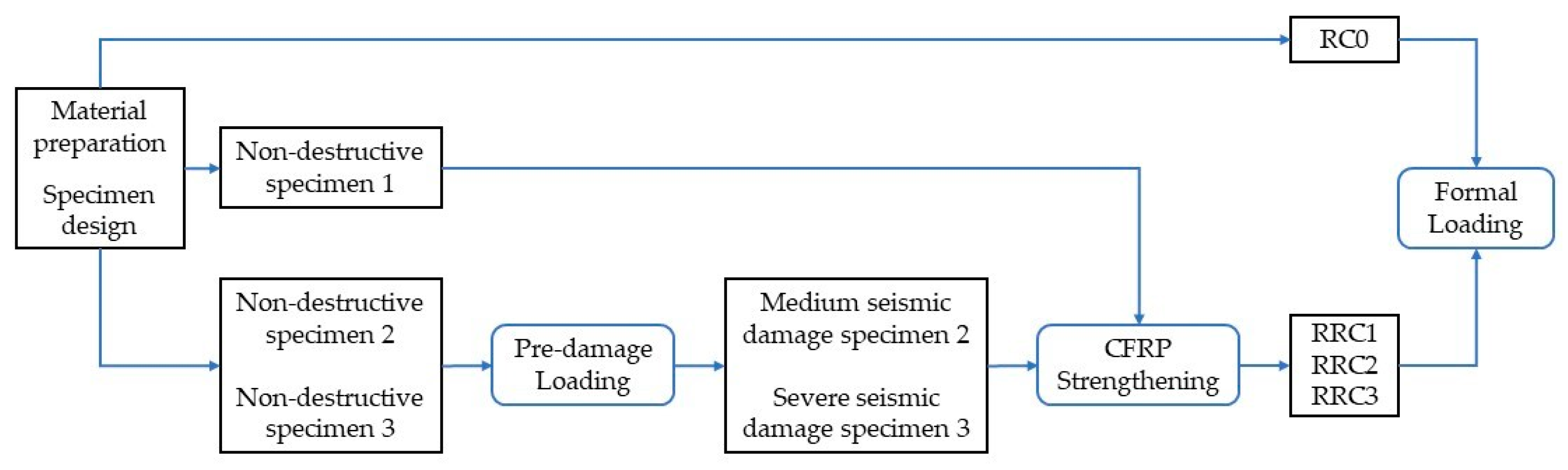
2.1. General Flow of the Experiment
The general flow of this experiment is shown in
Figure 1.
2.2. Specimen Design and Material Parameters
The four recycled concrete column specimens were loaded to achieve specific damage states. According to the level of seismic damages, the four specimens were defined as non-destructive without strengthening (prototype, RC0), non-destructive with strengthening (RRC1), medium seismic damage with strengthening (RRC2), and severe seismic damage with strengthening (RRC3). The detailed descriptions of the four specimens are shown in
Table 1.
The maximum particle size of recycled aggregate used in the specimens was 25 mm, and the water absorption of the recycled aggregate was 3.8%. CL0 was the control concrete with natural aggregate (0% recycled aggregate replacement), and CL50 was the concrete with 50% recycled aggregate replacement. The concrete material ratios are shown in
Table 2. Concrete material performance parameters were obtained from material properties experiments (
Table 3).
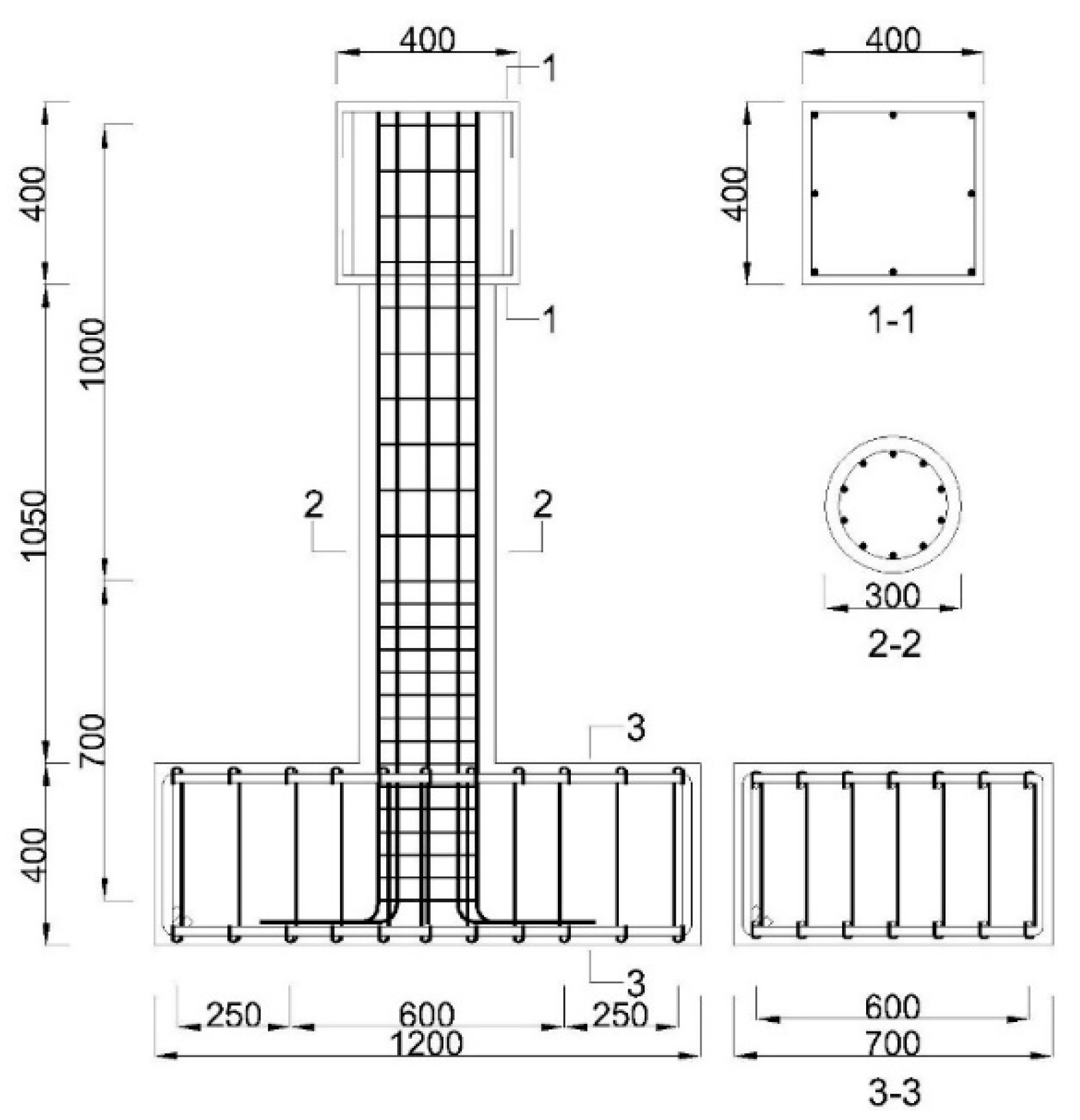
The geometric dimensions and reinforcement of the four specimens are the same. Taking RC0 as an example, the design schematic shown is in
Figure 2: the cross-sectional diameter of the column is 300 mm, the height of the column is 1050 mm, the cross-sectional size of the column head is 400 mm × 400 mm, and the cross-sectional size of the specimen cap is 400 mm × 700 mm. The longitudinal reinforcement and the hoop reinforcement are both HRB400 steel bars with diameters of 12 mm and 8 mm, respectively. The material properties of the reinforcement were obtained from the material property test (
Table 4).
The mechanical properties of the high-strength grout used in the strengthening process of the damaged recycled concrete columns were tested according to the test method of concrete materials. The measured cubic compressive strength of the grout was 68.41 MPa. The material mechanical parameters of CFRP, impregnating adhesive, and crack repair and leveling adhesive are shown in
Table 5.
2.3. Seismic Damage Control and Specimen Strengthening
The simulation and control of the seismic damage states of the specimens were mainly achieved by pre-damage treatment. The damage caused by the earthquake was simulated by loading the specimen repeatedly at low circumference [
26]. Based on the test of specimen loading, results, and previous research [
27], the specimen damage levels and the corresponding macroscopic test phenomena were summarized (
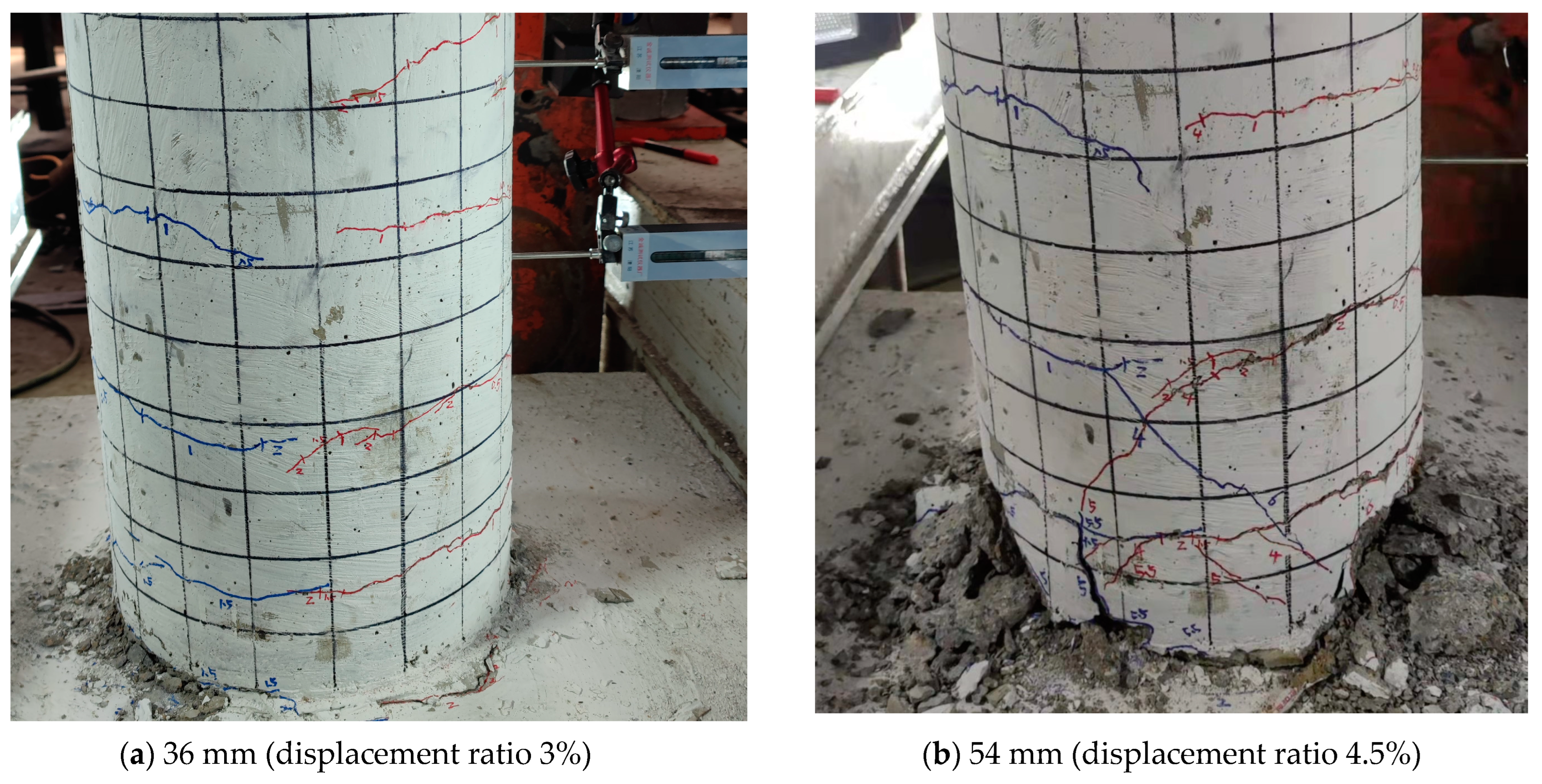
Table 6). Consequently, the pre-damage loading displacement of the column specimen in the medium seismic damage state is 36 mm (displacement ratio 3%), as shown in
Figure 3a. The per-damage loading displacement in the state of severe seismic damage is 54 mm (displacement ratio 4.5%), as shown in
Figure 3b, and the pre-damage parameters of each specimen are shown in
Table 7.
To produce the CFRP-strengthened seismic damage specimens, the pre-damaged specimen was cleaned to ensure the plastic hinge damage area and the surface of the specimen were clean and tidy; the damaged area was repaired with repair leveling adhesive and high-strength grout and maintained for 48 h; the surface of the specimen was cleaned again to further remove the surface dirt; the prepared impregnating adhesive and CFRP cloth were pasted on to the column. It should be noted that both sides of the CFRP cloth should be coated with impregnating adhesive. A squeegee was used to wipe off the excess glue when pasting. The CFRP and the surface of the specimen were ensured to be in full contact to avoid wrinkles. The strengthened specimens were maintained for 72 h.
The strengthening height of CFRP was 60 cm according to the plastic hinge and crack distribution of the specimens after pre-damage loading. The adhesive form of CFRP was in the form of plastic hinge reinforcement by combining transverse hoop and longitudinal paste.
2.4. Loading Device and Loading System
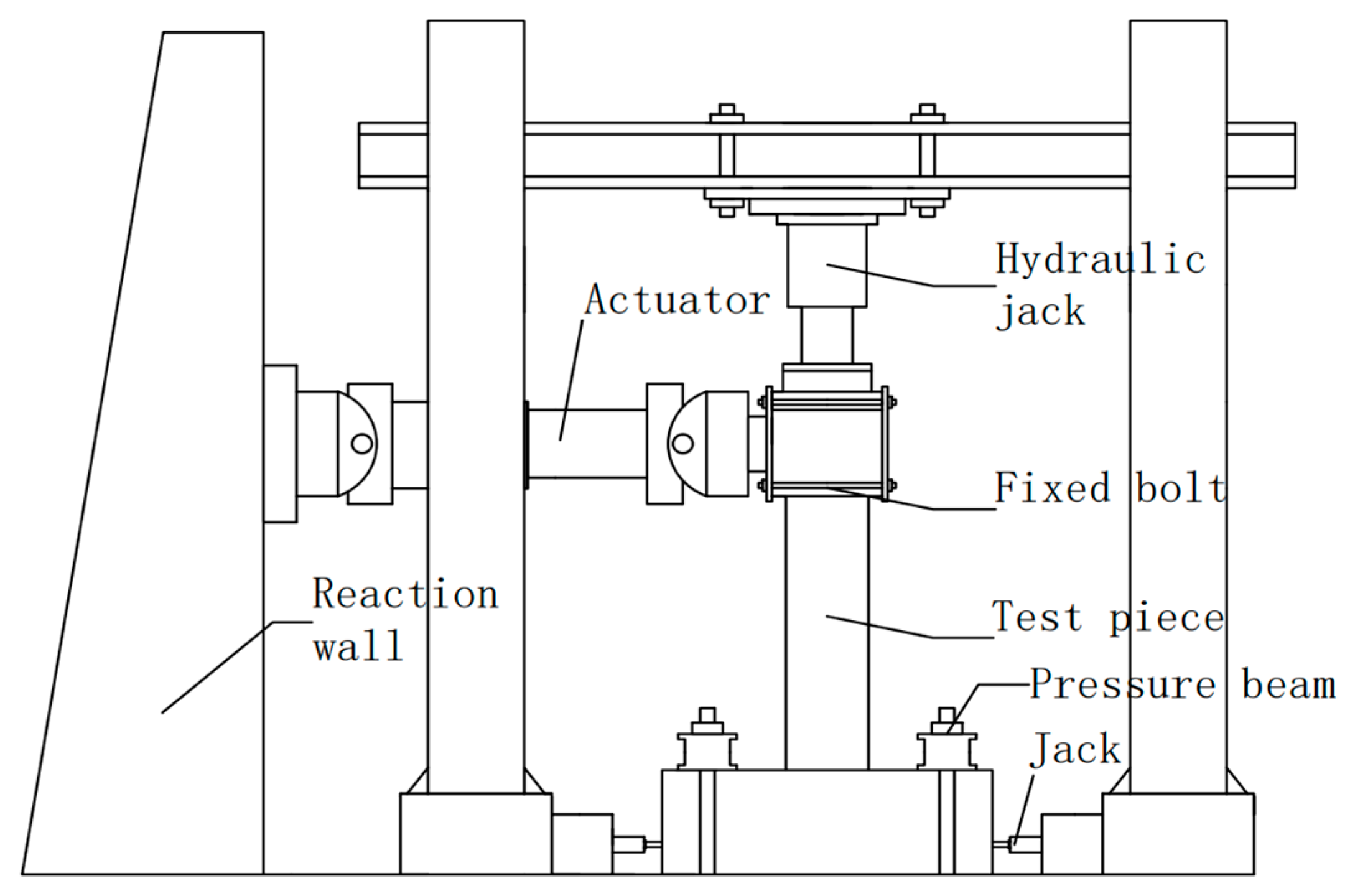
The test loading device is shown in
Figure 4. The specimen cap was rigidly anchored to the ground by high strength bolts. When the test began, the vertical load was applied to the top of the column by a hydraulic jack. The design axial pressure ratio is 0.2. The horizontal load on the top of the specimen was applied by an electro-hydraulic servo actuator.
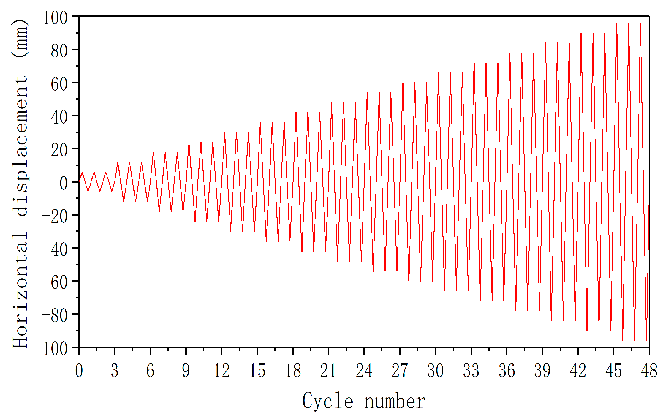
The loading regime was displacement-controlled loading with the amplitude of 6 mm three times (
Figure 5). When the bearing capacity of the specimen was reduced to 85% of the maximum horizontal load or when the reinforcement was pulled out and the core concrete was crushed in a large area, the loading was stopped.
2.5. Analysis of Test Phenomena
The four test specimens were divided into non-strengthened group (RC0) and strengthened group (RRC1, RRC2, RRC3). The results for the formally loaded specimens in both groups are shown in
Figure 6 and
Figure 7.
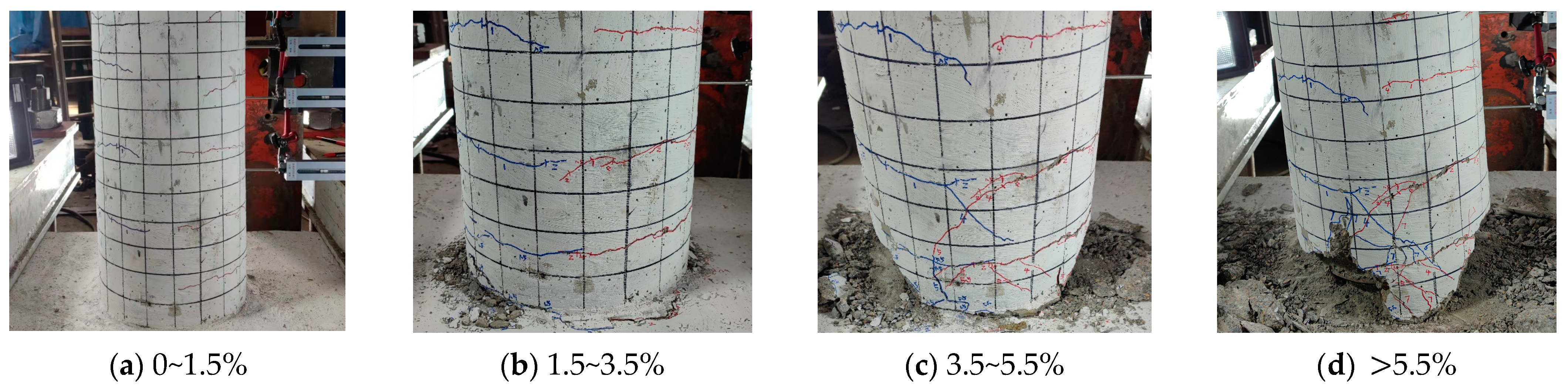
At the early stage of loading, when the loading displacement ratio was in the range of 0~1.5%, there was no obvious damage to the specimens, and only minor cracks appeared on the tensile side of the concrete in the protective layer of the specimens. The cracks were completely closed after the loading is returned to positive direction (
Figure 6a). When the loading displacement ratio was 1.5~3.5%, the concrete on the tensile side of the specimen appeared cracking and spalling with the increase of the number of cycles, and the longitudinal reinforcement was not exposed (
Figure 6b).
As the specimen continued to be loaded, the loading displacement ratio reached 3.5~5.5%, and the concrete cracking and spalling on both sides of the specimen became more serious. The cracks developed further. The concrete in the core area was partially crushed, as shown in
Figure 6c. When the loading displacement ratio was >5.5%, the specimen progressed into the damage stage. Due to the continuous accumulation of damage, the cracks developed continuously. Eventually, the concrete of the specimen spalled off extensively. The concrete in the core area was crushed extensively. The longitudinal reinforcement was exposed and the buckling phenomenon was obvious (
Figure 5d).
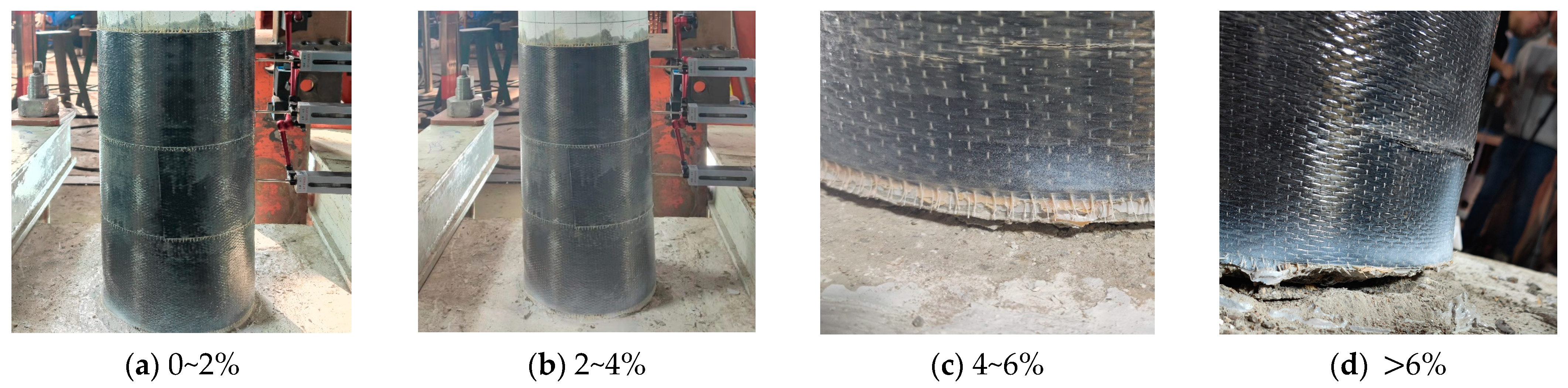
The results of the formal loading process of the three specimens in the strengthening group (RRC1, RRC2, and RRC3) were similar. When the loading displacement ratio was in the range of 0~2%, no damage was observed to the specimens, and the crack development of the specimens was not obvious due to the restraint of CFRP (
Figure 7a). A slight bulge on the compressed side of the specimen was observed when the loading displacement ratio was in the range of 2~4% as the number of cycles increased, and no obvious changes occurred on the tensile side. When the horizontal displacement was loaded in the reverse direction, the original compressive side became the tensile side, and cracks appeared at the junction of the column bottom and the bearing platform (
Figure 7b).
As the specimen loading continued, the loading displacement ratio reached 4~6%, and the crack at the bottom of the column was further developed. The concrete in the core area was partially crushed. The bulging phenomenon was obvious on the compressed side. The cracking of CFRP on the tensile side started to appear, as shown in
Figure 7c. When the loading displacement ratio was >6%, the specimen entered the damage stage. Through cracks appeared at the bottom of the column. The concrete in the core area and the surrounding concrete were crushed extensively. The bulging phenomenon on the pressurized side became more obvious and the CFRP was seriously cracked (
Figure 7d).
3. Analysis of Test Results
3.1. Hysteretic Curve
The measured hysteretic curves of each specimen are shown in
Figure 8.
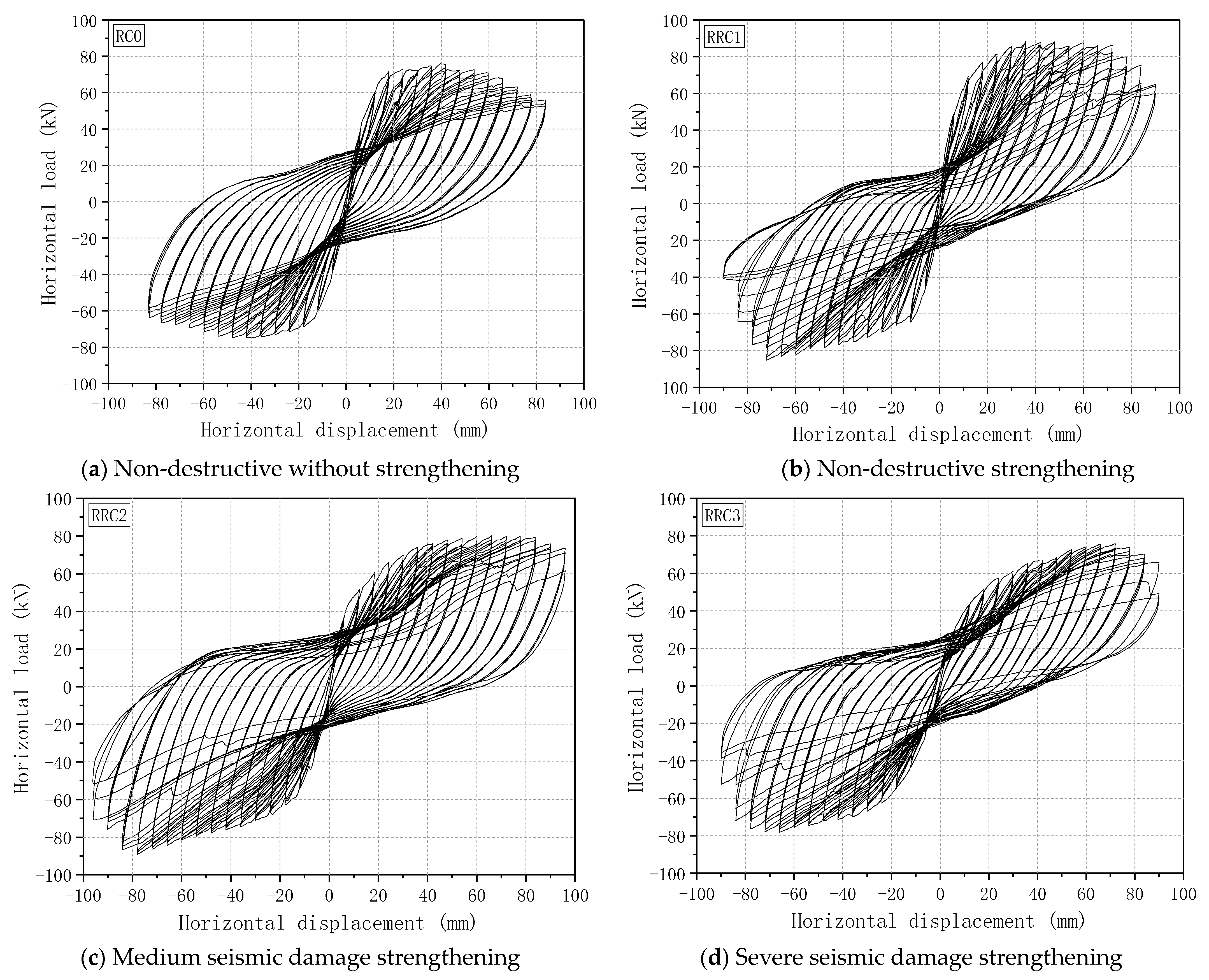
The hysteresis curves of the column specimens had some similarities (
Figure 8). At the initial stage of loading, the specimens were in an elastic state. The area enclosed by the hysteresis curve was small; the energy dissipation capacity of the specimen was weak. The stiffness degradation and residual deformation were not obvious. As the loading proceeded, the area enclosed by the hysteresis curve gradually increased, the energy dissipation capacity increased, and the stiffness degradation and residual deformation were more obvious. Overall, the hysteresis curve of RRC3 was narrower and longer compared to the other three specimens. The seismic damage level had a significant effect on the hysteresis curves of the strengthened specimens.
3.2. Skeleton Curve
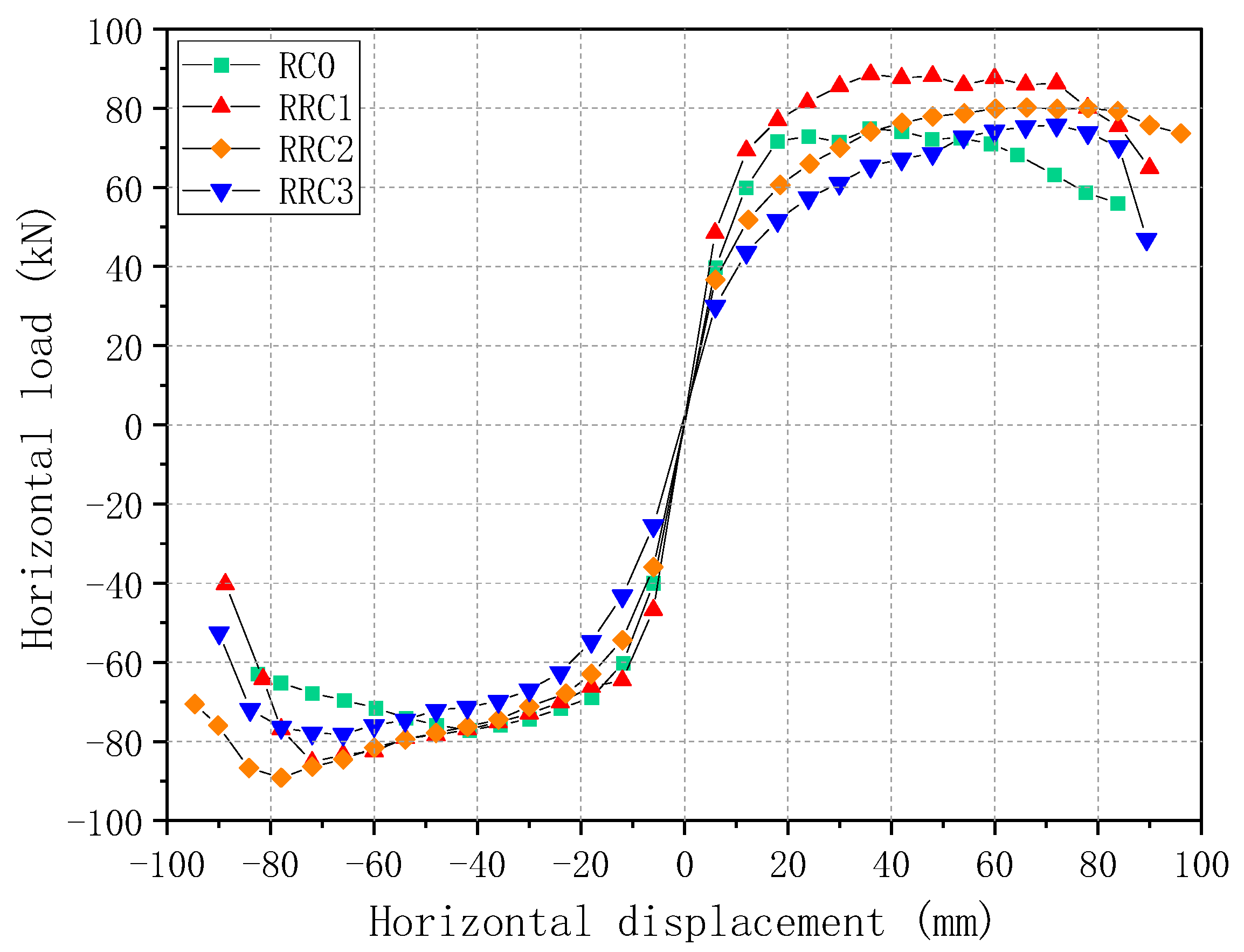
The comparative skeleton curves of each specimen are shown in
Figure 9. The skeleton curves of the four specimens were basically similar in shape: all included a rising section, peak point, and a falling section. Compared to the prototype specimen, the initial stiffness of the damaged strengthened specimens decreased and the yield displacement increased. The damaged strengthened specimens entered the yield state later than the prototype specimens with a larger difference in the location of the peak point. The yield displacements of the damaged strengthened specimens were relatively close to each other, and the bearing capacity had a long rising phase. Overall, the bearing capacity of the strengthened recycled concrete column specimen with severe seismic damage decreased most rapidly after reaching the peak load.
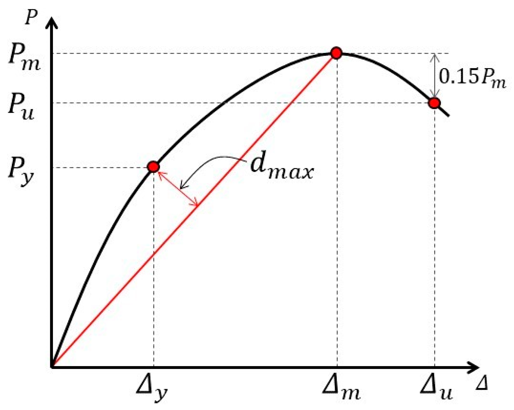
We use the “furthest point” method [
28,
29] to determine the yield point, peak point, and limit point of the skeleton curve, which are shown in
Figure 10.
The relevant indexes corresponding to the yield point, peak point, and limit point of the skeleton curve are shown in
Table 8. Compared to RC0, the peak bearing capacity of RRC1, RRC2, and RRC3 increased by 14.3%, 11.4%, and 1.19%, respectively. The yield displacement of RRC1, RRC2, and RRC3 increased by 0.4%, 52.9%, and 76.1%, respectively. The limit displacement of RRC1, RRC2, and RRC3 increased by 10.7%, 26.3%, and 15.9%, respectively. The peak load bearing capacity of RRC2 increased by 10.1% compared to RRC3. Therefore, CFRP had a significant effect on the recovery of the bearing capacity and ductility of the damaged recycled concrete columns. The level of seismic damage had a significant effect on the strengthening effect of CFRP.
3.3. Displacement Ductility Coefficient
The displacement ductility coefficient of the specimen was calculated with the ratio of the ultimate displacement
and the yield displacement
, using Equation (1):
The displacement ductility coefficients of the specimens are shown in
Table 9. The average displacement ductility coefficients of strengthened specimens were concentrated between 4.1 and 6.8. The average displacement ductility coefficient of the non-destructive strengthened specimen RRC1 was increased by 10.2% compared to that of the prototype RC0. The average displacement ductility coefficients of RRC2 and RRC3 reached 82.5% and 67.1% of that of RC0, respectively. The average displacement ductility coefficient of RRC2 was 22.9% higher than that of RRC3. The ductility of the recycled concrete column specimens with different seismic damages recovered and improved to different levels after the CFRP strengthening. When the seismic damage to the specimens was severe, the effect of CFRP was weak on the recovery and improvement of the ductility of the specimens. In general, CFRP had better ductility recovery and improvement for specimens with medium and lower seismic damage levels.
3.4. Strength Degradation
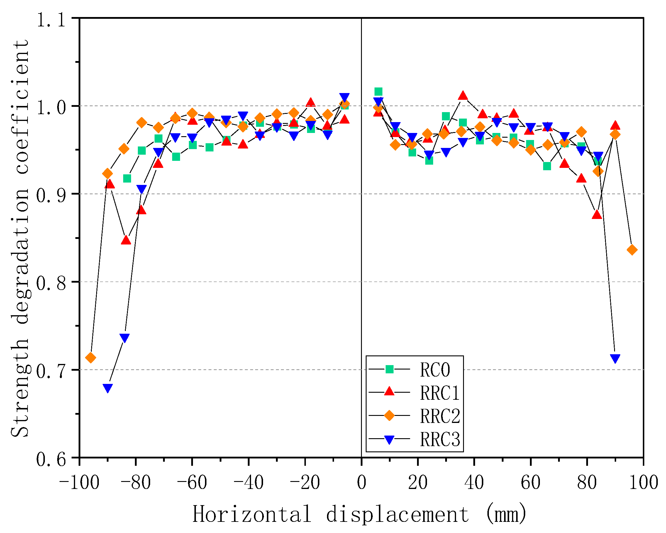
The strength degradation of the specimen is measured by the strength degradation coefficient
η, which is defined as the ratio of the peak bearing capacity of the last cycle of the displacement to that of the first cycle. It is calculated with Equation (2)
where
is the peak bearing capacity of the first cycle of the
i-th displacement stage and
is the peak bearing capacity of the last cycle of the i-th displacement stage. The strength degradation curves of the specimens are shown in
Figure 11. On the whole, the strength degradation coefficients of each specimen were concentrated between 0.9 and 1.0.
The bearing capacities of the four specimens were generally degraded with the loading. RRC1, RRC2, and RRC3 were more stable in bearing capacity even if the horizontal displacement increased before reaching the peak load. The bearing capacity degradation curve was relatively smooth and showed good ductility, which indicated that CFRP had a good strengthening effect on the recycled concrete column specimens with different levels of seismic damage under large lateral displacement conditions (
Figure 9). After reaching the peak load, the bearing capacity of RRC2 and RRC3 degraded more rapidly, which may be due to the bulging and tearing of the outsourced CFRP and the weakening of the restraint on the concrete in the core area. In general, the level of seismic damage of the recycled concrete column specimens had a large influence on the strength degradation coefficient. The CFRP strengthened bearing capacity was more stable when the initial seismic damage of the specimens was lower, and it was easier to maintain the strength.
3.5. Stiffness Degradation
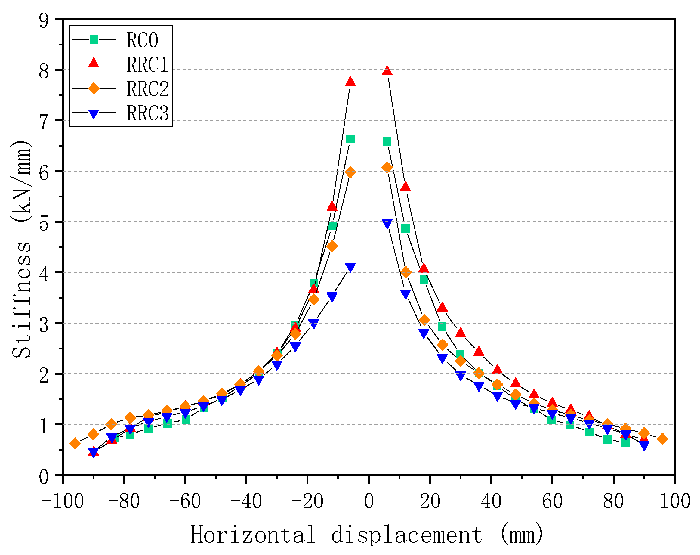
Stiffness degradation is characterized by the average secant stiffness
in the positive and negative directions at all levels of the hysteretic curve, as obtained by Equation (3).
where
represents the average value of peak load in positive and negative directions for each stage, and
represents the average value of maximum displacement in positive and negative directions for each stage.
The stiffness degradations of the four specimens are shown in
Figure 12.
The stiffness degradations of the four specimens were similar as the load increased (
Figure 12). The stiffness decreased as the displacement increased. The initial stiffness of RC0 was 6.61 kN/mm. The initial stiffness of RRC1 was 7.85 kN/mm, RRC2 was 6.03 kN/mm, and RRC3 was 4.55 kN/mm. The initial stiffness was smaller when the seismic damage was more severe. The CFRP strengthening did not significantly enhance the initial stiffness of the specimens. As the load proceeded, the stiffness degradation of the specimens slowed down, which indicated that the effect of CFRP on the stiffness of the recycled concrete column specimens with seismic damage gradually appeared as the load proceeded. Overall, the stiffness improvement was most significant after strengthening of non-destructive recycled concrete column specimens. The stiffness of the medium seismic damage recycled concrete column would be effectively improved and restored after strengthening. The stiffness was recovered, but not significantly, after strengthening of the severe damage recycled concrete column. The stiffness restoration and improvement of damaged recycled concrete columns strengthened with CFRP were more evident for the medium damage and non-damage recycled concrete columns.
3.6. Energy Dissipation Capacity
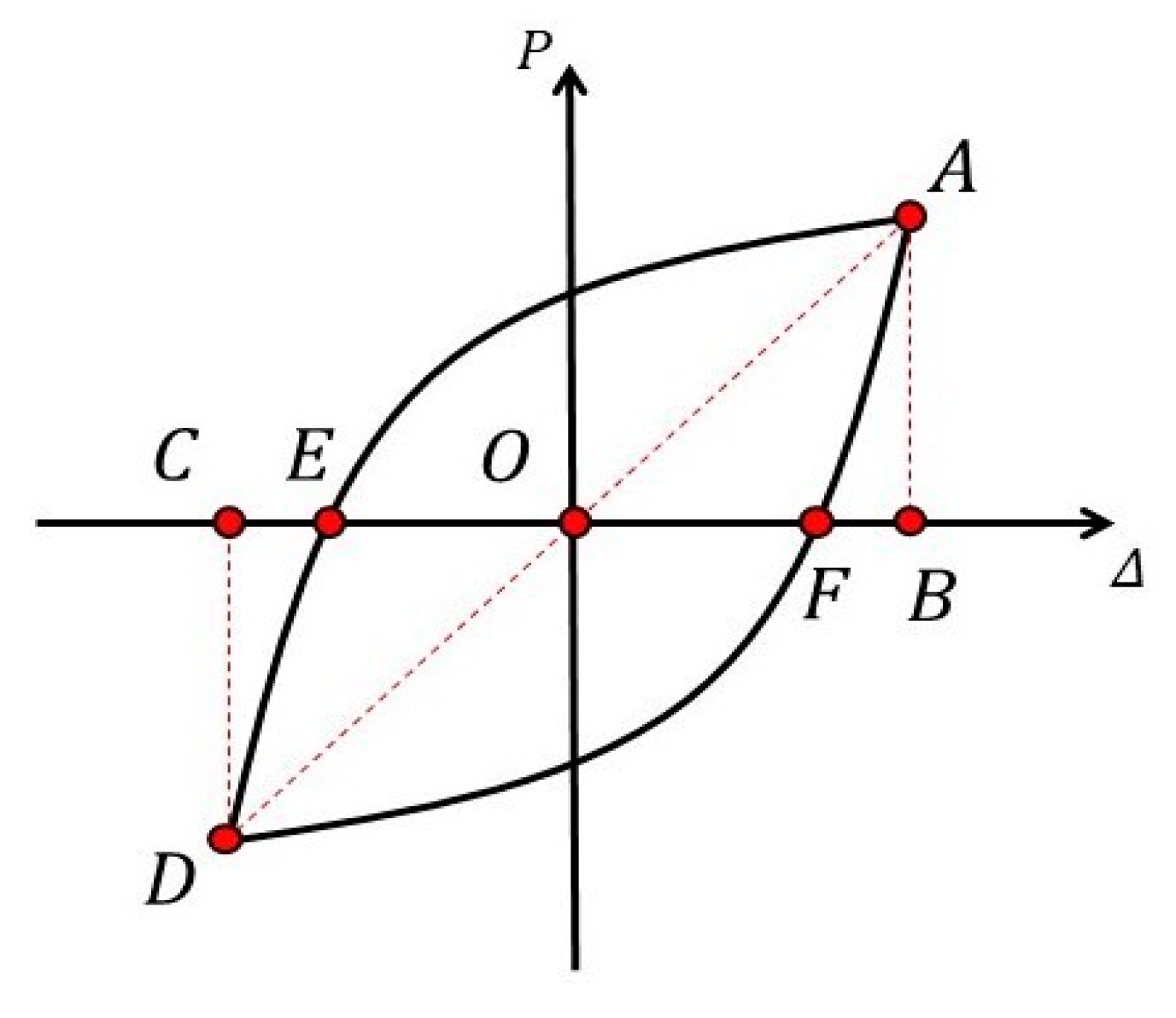
The energy dissipation capacity of the specimen is mainly determined by the equivalent viscous damping coefficient and the accumulated energy dissipation. The equivalent viscous damping coefficient is calculated by Equation (4).
where
is the area of the hysteresis loop and
is the area of triangle
OAB.
is the area of triangle
OCD (
Figure 13).
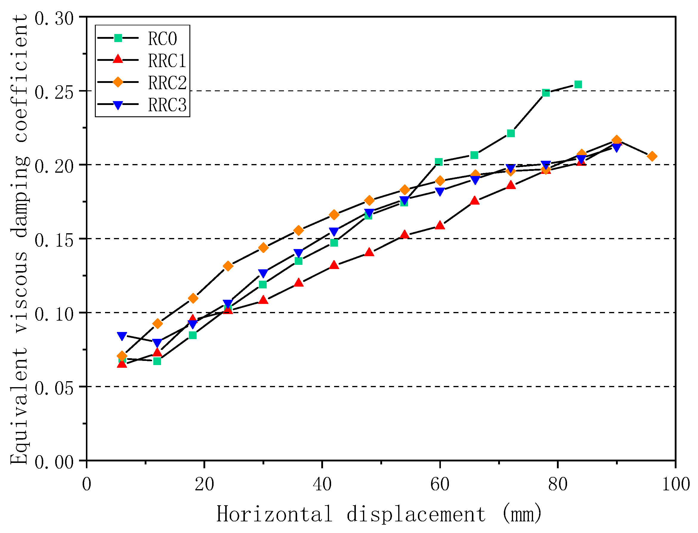
The equivalent viscous damping coefficients of the specimens showed an increasing as shown in
Figure 14. In most of the loading stages, the equivalent viscous damping coefficients of RRC2 and RRC3 were higher than those of RC0 and RRC2. As the specimens were continuously loaded, the CFRP was torn and damaged, and the restraint effect on the core concrete was weakened, the rising trend of the equivalent viscous damping coefficient at the end of loading was not obvious. The equivalent viscous damping coefficient of RRC2 had significantly improved compared to RRC3. The CFRP had better strengthening effect on the medium seismic damage specimen. In general, the level of initial seismic damage had a great influence on the equivalent viscous damping coefficient of the specimens. CFRP strengthening was beneficial to the improvement of the energy dissipation capacity of the specimens.
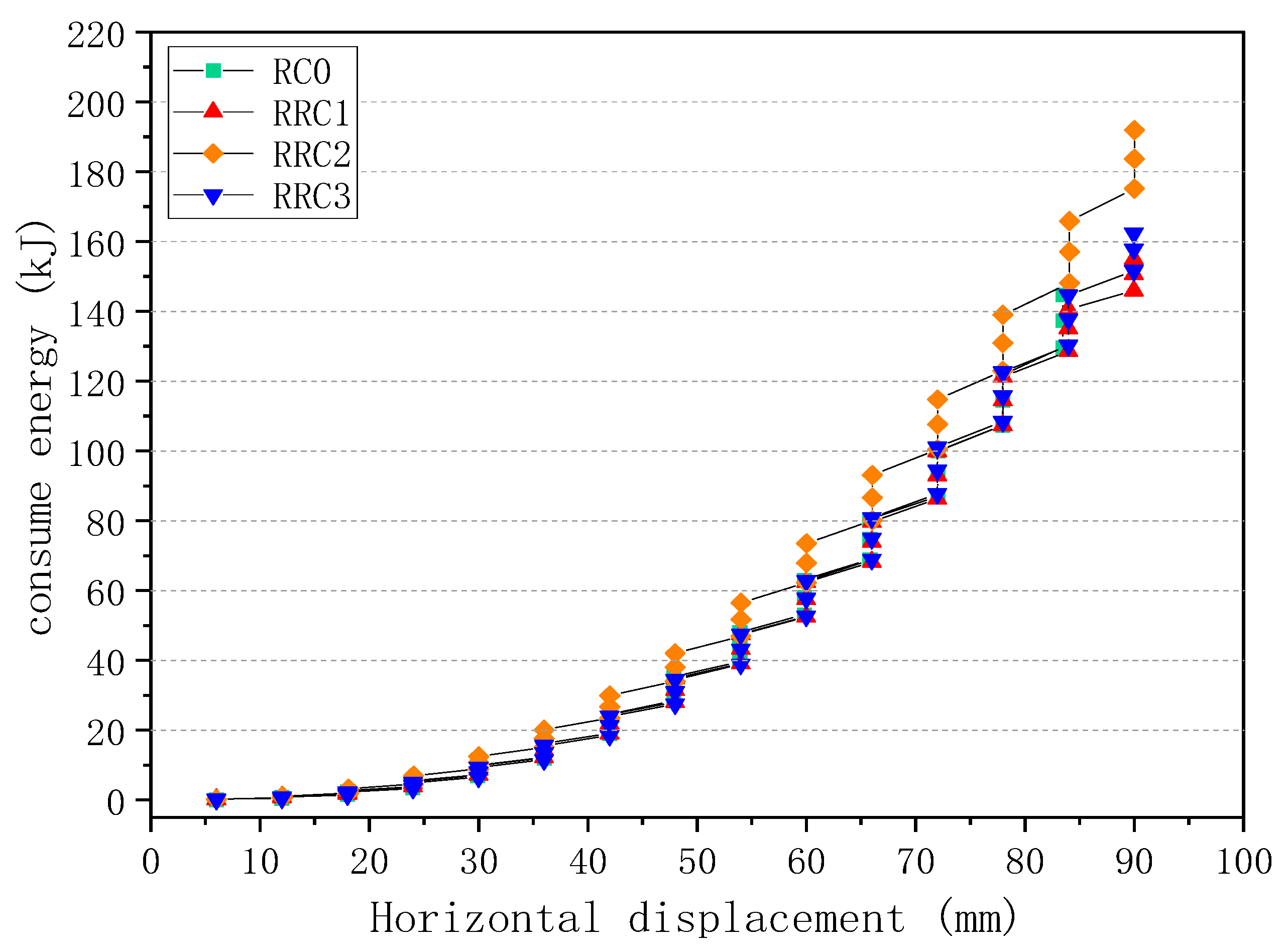
The trends of cumulative energy dissipation of the specimens are shown in
Figure 15. The energy dissipation capacities of the CFRP-strengthened recycled concrete column specimens increased compared to the prototype specimen. Especially for the medium seismic damaged specimen, the energy dissipation increased more significantly. The energy dissipation trend of the severely damaged strengthened specimen was almost the same as that of the prototype specimen.
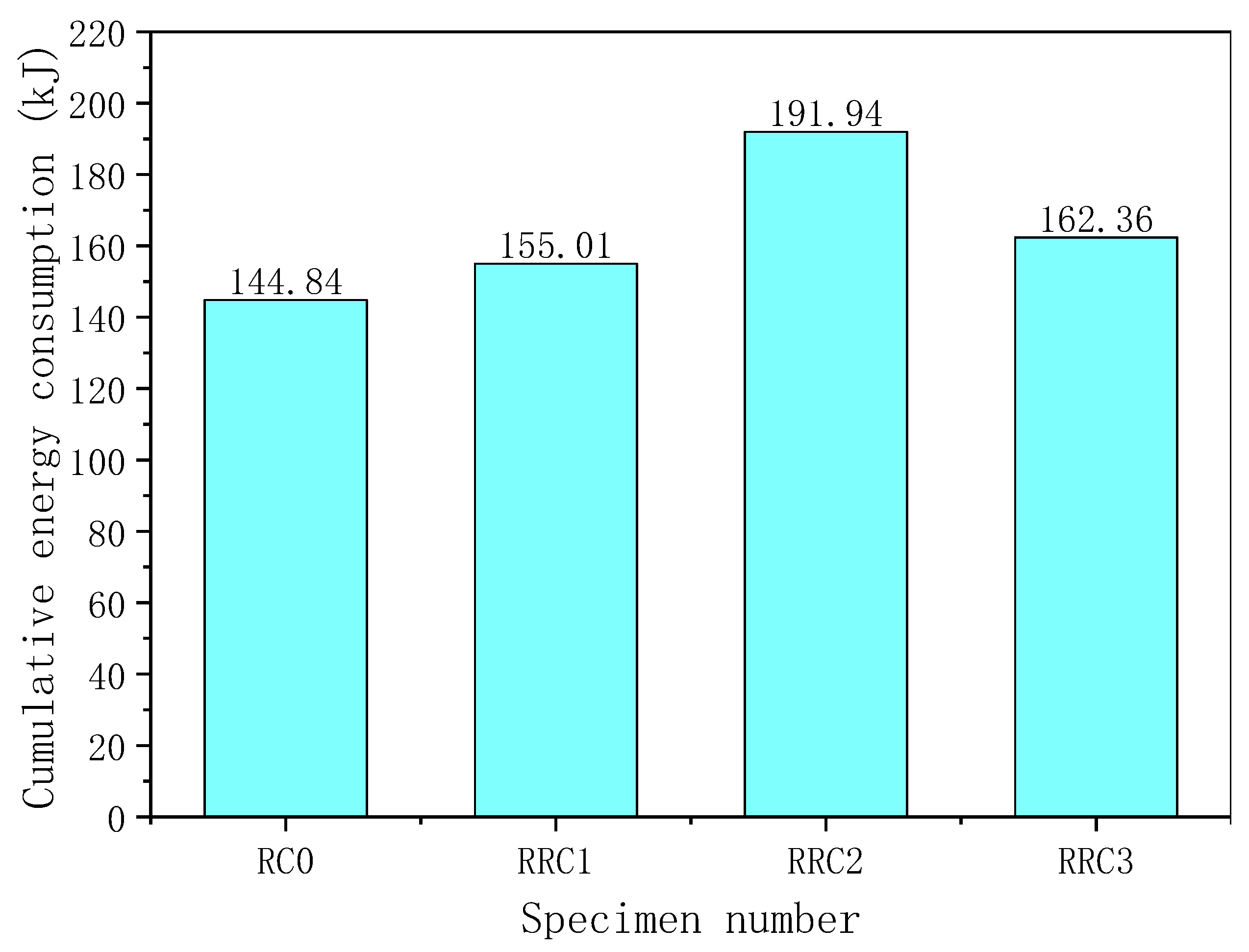
The comparison of the cumulative energy dissipation of the four specimens is shown in
Figure 16. Compared to RC0, the cumulative energy dissipation of RRC1, RRC2, and RRC3 were increased by 7.1%, 32.5%, and 12.1%, respectively. The cumulative energy dissipation of RRC2 increased by 18.2% compared to RRC3. In general, the use of recycled concrete and CFRP strengthening showed the most significant improvement in cumulative energy dissipation for the recycled concrete column specimen with medium seismic damage.
4. Numerical Model Analysis
4.1. Material Model
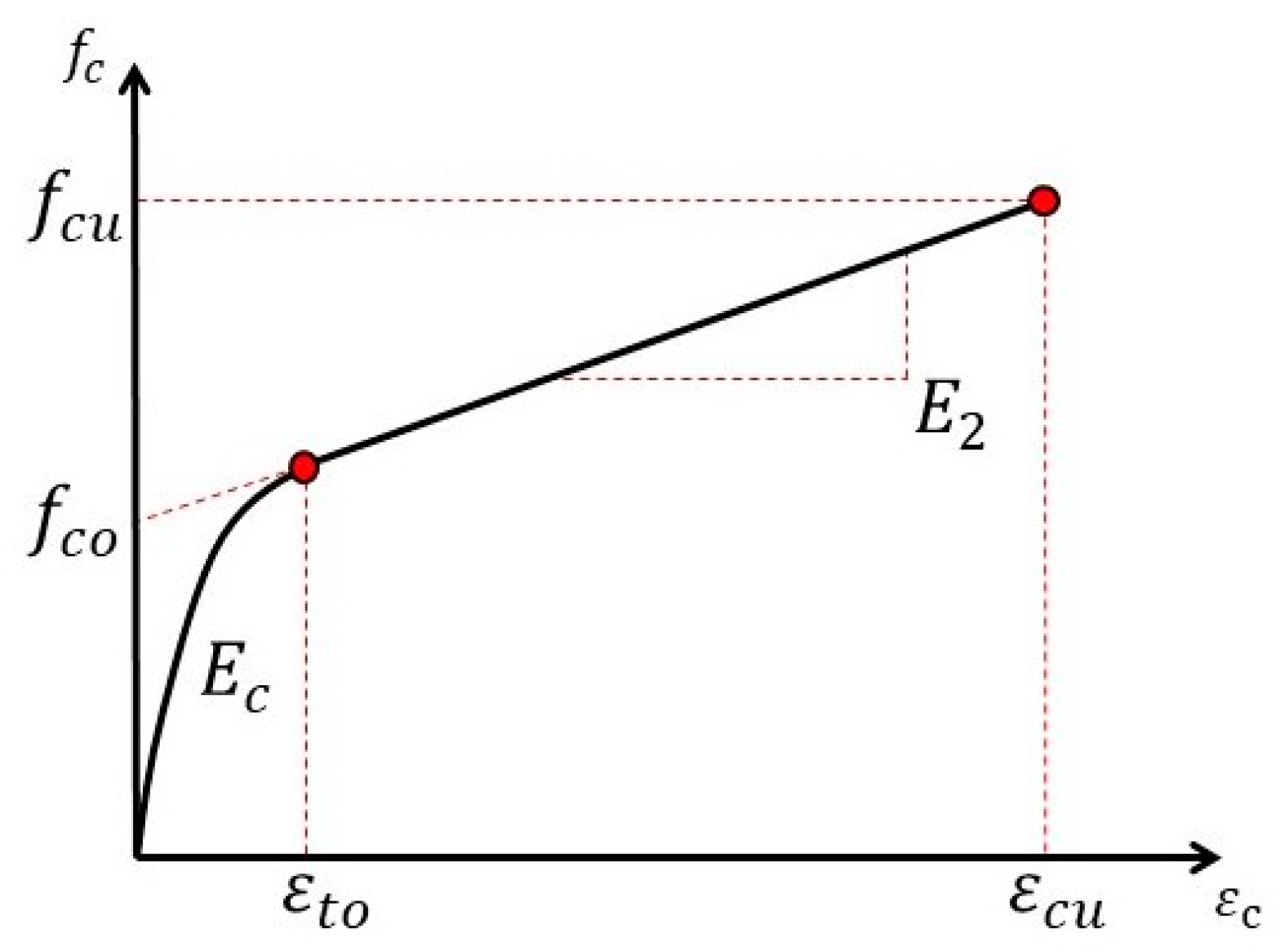
In this study, the concrete material in the non-repaired area was simulated using the Concrete02 model, and the restraint effect of hoop reinforcement on the concrete in the core area was also considered. For the concrete in the repaired area, the principal structure relationship of FRP-constrained concrete proposed by Lam and Teng [
30] was used, as shown in
Figure 17. Due to the limited effect of post-earthquake hoop reinforcement on the concrete restraint in the core area, the restraint effect of hoop reinforcement was not considered in the repaired area.
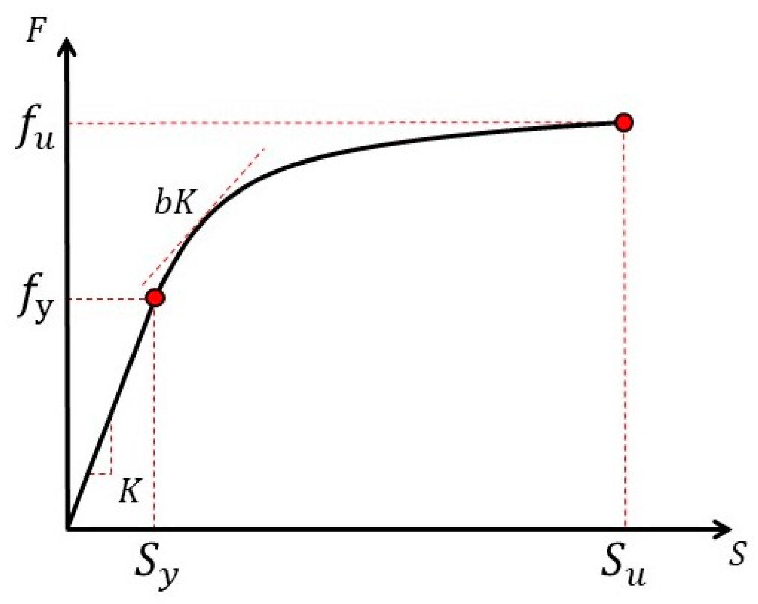
In earthquakes, the longitudinal reinforcement at the connection between the column and the bearing produced a bond slip, which caused additional rotation of the column. The Bond_SP01 model in OpenSees was used. The stress–slip skeleton curve of the longitudinal reinforcement of this model is calculated with Equation (5) and shown in
Figure 18.
where
is the diameter of the longitudinal reinforcement;
is the slip corresponding to the yielding of the longitudinal reinforcement;
is the yield strength of the longitudinal reinforcement;
is the compressive strength of concrete;
is the local cohesive slip factor, taken as 0.4;
is the limiting slip in the range of 30~40
; K is the stiffness of the elastic section of the stress–slip relationship of the longitudinal reinforcement; b is the reduction factor of stiffness in the nonlinear phase, which is between 0.3 and 0.5.
The reinforcing steel model, which reflects the fatigue and buckling of the reinforcement, was used for the simulation of the steel material. The damage of the longitudinal reinforcement in the repaired area of the specimen was considered. In this study, we adapted the reduction method of elastic modulus of reinforcement proposed by Vosooghi and Saiidi [
31]. The modulus of elasticity in the model was multiplied by the corresponding reduction factor to obtain the modified intrinsic structure relationship. The value of the reduction factor
is related to the damage of the specimen, as shown in
Table 10.
4.2. Model Building
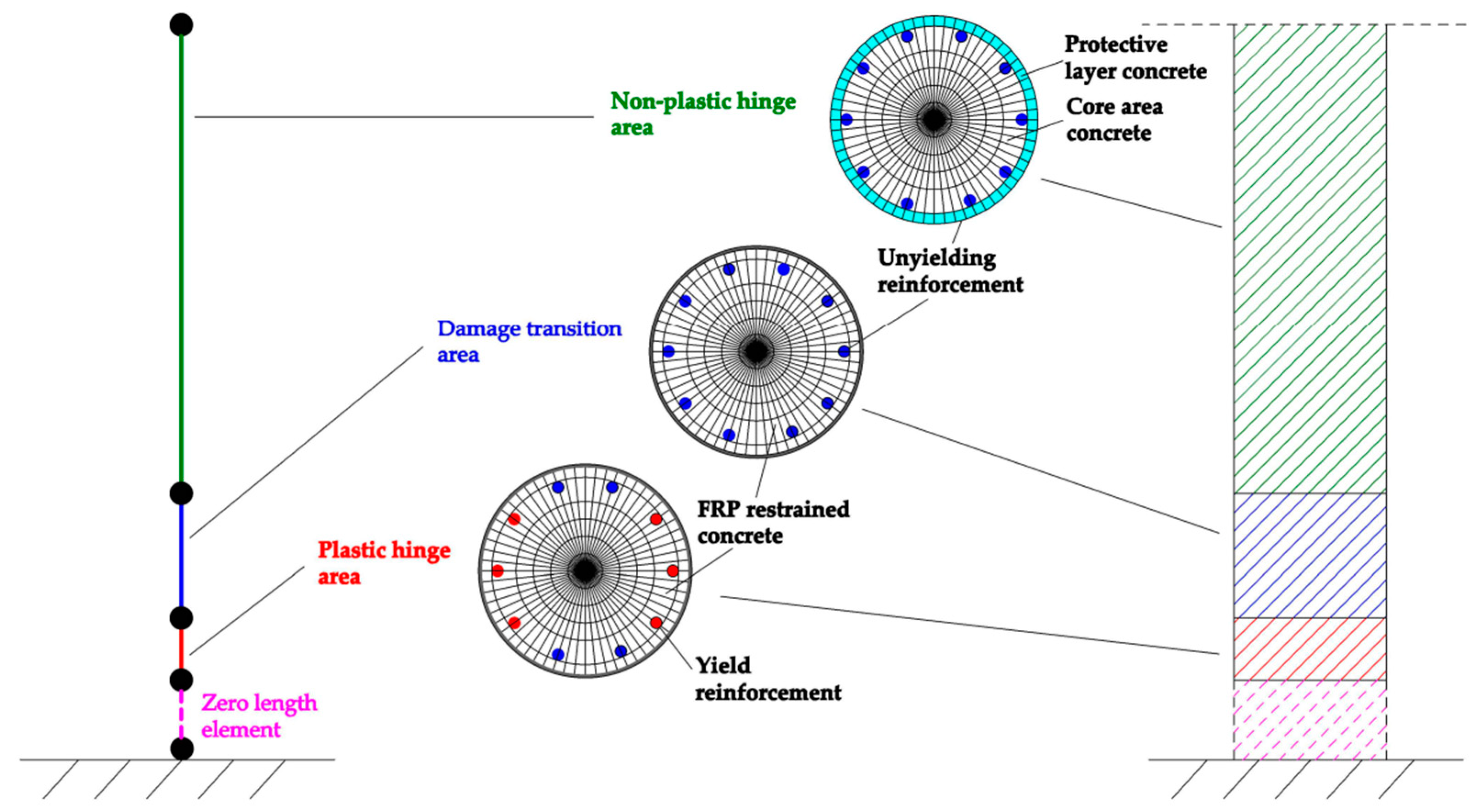
The numerical analysis model is shown in
Figure 19.
The column was simulated by a fiber beam-column element, which was divided into three parts. The upper part was used to simulate the non-plastic hinge area, the middle part was used to simulate the damage transition area, and the lower part was used to simulate the plastic hinge area. The bond slip at the column-bearing joint was simulated by a zero-length element. Based on the test phenomenon and the obtained data, the plastic hinge height of the specimen
was 20 cm [
32,
33]. The height of the damage transition area was taken as 2 times
. Based on the relevant indicators in
Table 10, the values of the reduction factors
for RRC1, RRC2, and RRC3 are taken as shown in
Table 11.
4.3. Model Validation
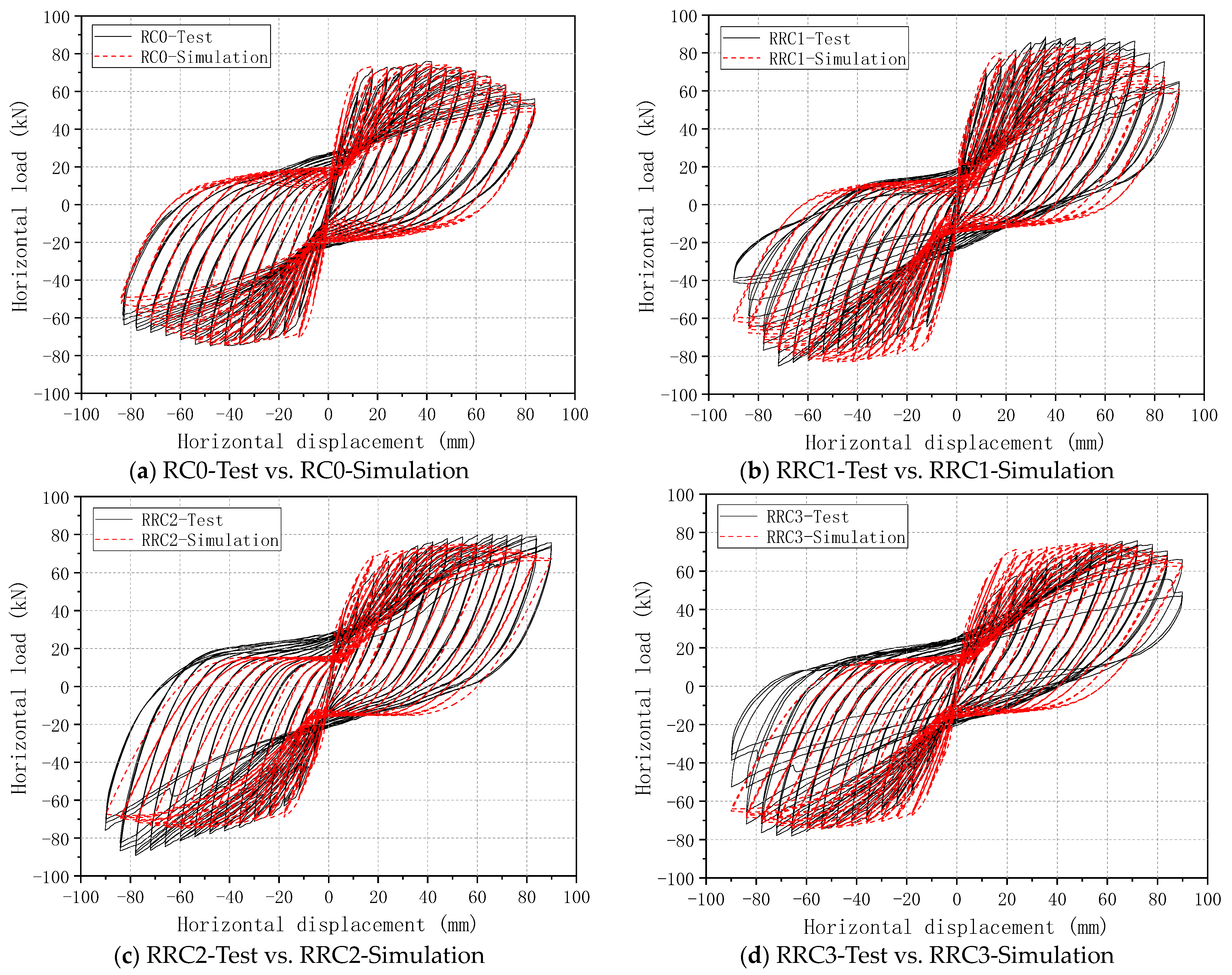
A comparison of the simulation results with the test results is shown in
Figure 20.
Overall, the simulation results were in general agreement with the test results. The initial stiffness, bearing capacity, and deformation capacity of the specimens obtained from the simulation were close to the test results. However, with the increase in the seismic damage level, differences between the simulation results and the test results were observed in the later stage of loading. This is mainly due to the complexity of the damage to the seismically damaged strengthened specimens. The effects of bond slip between reinforcement and concrete, the development and distribution of recycled concrete damage, and the differences between the working properties of CFRP and various repair materials at different levels of seismic damage on the test results were manifold and need to be further investigated.
5. Conclusions
The damages to the four specimens were all caused by the plastic hinge at the bottom of the column. The strengthening effect of CFRP gradually weakened as the seismic damage level increased. Overall, the CFRP was more effective for strengthening the recycled concrete column specimens with medium and lower seismic damage levels (displacement ratio ≤ 3%).
Compared to the intact prototype specimen, the peak bearing capacities of RRC1, RRC2, and RRC3 increased by 14.3%, 11.4%, and 1.19%, the yield displacements increased by 0.4%, 52.9%, and 76.1%, and the ultimate displacements increased by 10.7%, 26.3%, and 15.9%, respectively. The peak bearing capacity of the RRC2 was higher than that of RRC3, by 10.1%, as the level of seismic damage was reduced. The displacement ductility coefficient increased by 22.9%, indicating that CFRP strengthening exhibited different effects on the performance of the recycled concrete column specimens under different seismic damages, and the restoration and improvement effects on medium damaged recycled concrete specimens are better.
Compared to the intact prototype specimen, the cumulative energy dissipations of RRC1, RRC2, and RRC3 increased by 7.1%, 32.5%, and 12.1%, respectively. The cumulative energy dissipation of RRC2 increases by 18.2% compared to RRC3, which indicated that the recycled concrete, CFRP, and the level of seismic damage of the specimens all affected the energy dissipation capacity of the strengthened specimens. Overall, the CFRP strengthening significantly improved the cumulative energy dissipation capacity of the recycled concrete column specimens with medium seismic damage.
A numerical analysis model of CFRP-strengthened seismic damaged recycled concrete columns was established with the OpenSees platform. The simulation results generally agreed with the experimental results. The modeling method in this study can model the basic mechanical characteristics of the repaired seismically damaged recycled concrete columns. However, with the increase in the seismic damage level, the agreement between the simulation results and the experimental results decreased. Due to the complexity of the damage of the seismic damaged strengthening specimens, factors such as the bond slip of reinforcement and concrete, the damage development mechanism of recycled concrete, and the difference of bonding ability between CFRP and various repair materials and existing concrete have a great influence on the results. There are still deficiencies in the numerical modeling studies of damaged strengthened members in related fields. We will further elucidate the performance trends in damaged strengthened specimens under different seismic damage levels.
Overall, this study provides an intuitive analysis of the advantages and disadvantages of CFRP strengthening of recycled concrete specimens at different levels of seismic damage. A new perspective was proposed for the practical application of CFRP in the repair of damaged structures. The results can also provide a reference basis for the promotion of using recycled concrete.
Author Contributions
Conceptualization, S.S.; methodology, S.S. and Z.T.; software, Z.T. and Z.T.; validation, X.L. and J.Z.; formal analysis, S.S. and Z.T.; investigation, S.S. and Z.Z.; resources, S.S.; data curation, Z.T.; writing—original draft preparation, Z.T.; writing—review and editing, S.S.; visualization, B.X.; supervision, S.S.; project administration, B.X.; funding acquisition, S.S. All authors have read and agreed to the published version of the manuscript.
Funding
This research was funded by “National Natural Science Foundation of China, grant number 51808376” and “China Postdoctoral Science Foundation, grant number 2019M651076”.
Data Availability Statement
Acknowledgments
The authors acknowledge Jing Liu for polishing the language.
Conflicts of Interest
The authors declare no conflict of interest.
References
- Zhang, L.W.; Sojobi, A.O.; Liew, K.M. Sustainable CFRP-reinforced recycled concrete for cleaner eco-friendly construction. J. Clean. Prod. 2019, 233, 56–75. [Google Scholar] [CrossRef]
- Xue, X.; Gao, J.; Hu, K. Performance Evaluation of Cement Stabilized Mixture with Recycled Aggregate from Construction and Demolition Waste. Iran. J. Sci. Technol. Trans. Civ. Eng. 2022, 46, 3093–3106. [Google Scholar] [CrossRef]
- Prieto, M.; González García, M.; Cobo, A.; Alonso, D. Comparison of the Mechanical Behavior of Concrete Containing Recycled CFRP Fibers and Polypropylene Fibers. Appl. Sci. 2021, 2021, 10226. [Google Scholar] [CrossRef]
- Huang, Y.; Wang, J.; Ying, M.; Ni, J.; Li, M. Effect of particle-size gradation on cyclic shear properties of recycled concrete aggregate. Constr. Build. Mater. 2021, 301, 124143. [Google Scholar] [CrossRef]
- Dong, J.F.; Wang, Q.Y.; Guan, Z.W. Structural behaviour of recycled aggregate concrete filled steel tube columns strengthened by CFRP. Eng. Struct. 2013, 48, 532–542. [Google Scholar] [CrossRef]
- Tang, H.; Chen, J.; Yue, Z.; Jia, Y.; Yuan, Z. Theoretical and numerical analysis on the ultimate bearing capacity of CFRP-confined CFSST stub columns. Arch. Civ. Mech. Eng. 2021, 22, 26. [Google Scholar] [CrossRef]
- Isleem, H.F.; Jagadesh, P.; Qaidi, S.; Althoey, F.; Rahmawati, C.; Najm, H.M.; Sabri, M.M.S. Finite element and theoretical investigations on PVC-CFRP confined concrete columns under axial compression. Front. Mater. 2022, 9, 1055397. [Google Scholar] [CrossRef]
- Yurdakul, O.; Avsar, O. Structural repairing of damaged reinforced concrete beam-column assemblies with CFRPs. Struct. Eng. Mech. 2015, 54, 521–543. [Google Scholar] [CrossRef]
- Tang, Z.; Li, W.; Tam, V.W.Y.; Yan, L. Mechanical performance of CFRP-confined sustainable geopolymeric recycled concrete under axial compression. Eng. Struct. 2020, 224, 111246. [Google Scholar] [CrossRef]
- Jia, P.; Dong, J.; Yuan, S.; Wang, Q. Experimental Study of Post-heated Steel Reinforced Recycled Concrete Columns Repaired with CFRP. J. Wuhan Univ. Technol. Mater. Sci. Ed. 2018, 33, 901–907. [Google Scholar] [CrossRef]
- Tang, Z.; Li, W.; Tam, V.W.Y.; Yan, L. Mechanical behaviors of CFRP-confined sustainable geopolymeric recycled aggregate concrete under both static and cyclic compressions. Compos. Struct. 2020, 252, 112750. [Google Scholar] [CrossRef]
- Sojobi, A.O.; Liew, K.M. Flexural behaviour and efficiency of CFRP-laminate reinforced recycled concrete beams: Optimization using linear weighted sum method. Compos. Struct. 2021, 260, 113259. [Google Scholar] [CrossRef]
- Li, P.; Sui, L.; Xing, F.; Zhou, Y. Static and cyclic response of low-strength recycled aggregate concrete strengthened using fiber-reinforced polymer. Compos. Part B Eng. 2019, 160, 37–49. [Google Scholar] [CrossRef]
- Kabir, M.I.; Subhani, M.; Shrestha, R.; Samali, B. Experimental and theoretical analysis of severely damaged concrete beams strengthened with CFRP. Constr. Build. Mater. 2018, 178, 161–174. [Google Scholar] [CrossRef]
- Zhou, C.; Qiu, Y.; Pan, Q. Experimental Investigation of Axial Compressive Behavior of Large-Scale Circular Concrete Columns Confined by Prestressed CFRP Strips. J. Struct. Eng. 2019, 145, 04019070. [Google Scholar] [CrossRef]
- Ma, H.; Wu, Y.A.; Huang, C.; Zhao, Y.L. Mechanical properties and bearing capacity of CFRP confined steel reinforced recycled concrete columns under axial compression loading. Struct. Eng. Mech. 2021, 79, 451–472. [Google Scholar]
- Ozcan, O.; Binici, B.; Canbay, E.; Ozcebe, G. Repair and strengthening of reinforced concrete columns with CFRPs. J. Reinf. Plast. Compos. 2010, 29, 3411–3424. [Google Scholar] [CrossRef]
- Yang, J.; Liang, S.T.; Zhu, X.J.; Dang, L.J.; Wang, J.L.; Tao, J.X. Experimental research and finite element analysis on the seismic behavior of CFRP-strengthened severely seismic-damaged RC columns. Structures 2021, 34, 3968–3981. [Google Scholar] [CrossRef]
- Yang, Y.; Sneed, L.; Saiidi, M.S.; Belarbi, A.; Ehsani, M.; He, R. Emergency repair of an RC bridge column with fractured bars using externally bonded prefabricated thin CFRP laminates and CFRP strips. Compos. Struct. 2015, 133, 727–738. [Google Scholar] [CrossRef]
- Yang, Y.; Sneed, L.H.; Morgan, A.; Saiidi, M.S.; Belarbi, A. Repair of RC bridge columns with interlocking spirals and fractured longitudinal bars—An experimental study. Constr. Build. Mater. 2015, 78, 405–420. [Google Scholar] [CrossRef]
- Lavorato, D.; Nuti, C. Pseudo-dynamic tests on reinforced concrete bridges repaired and retrofitted after seismic damage. Eng. Struct. 2015, 94, 96–112. [Google Scholar] [CrossRef]
- Jin, L.; Li, P.; Wang, Z.H.; Du, X.L. Effect of Size on Eccentric Compression Behavior of CFRP-Confined RC Columns: Experimental and Numerical Investigation. J. Compos. Constr. 2021, 25, 04021032. [Google Scholar] [CrossRef]
- Zhang, Z.; Cao, F.; Yang, J.; He, Z. Experiment on Natural Frequency Change of Reinforced Concrete Members under Low Cycle Loading. Shock. Vib. 2018, 2018, 6504519. [Google Scholar] [CrossRef]
- Lao, X.J.; Han, X.L.; Ji, J.; Chen, B.B. The compression behavior of CFRP-repaired damaged square RC columns. Constr. Build. Mater. 2019, 223, 1154–1166. [Google Scholar] [CrossRef]
- Shen, P.; Zhou, X. Experimental study on the seismic behavior of CFRP-strengthened seismic-damaged recycled aggregate concrete-filled rectangular steel tube frame columns. J. Build. Eng. 2022, 45, 103422. [Google Scholar]
- Gahmousse, Z.; Djebbar, M.S.; Djebbar, N. Seismic performance of RC columns retrofitted by CFRP wrapping ‘Study of the influencing parameters’. Asian J. Civ. Eng. 2021, 22, 911–928. [Google Scholar] [CrossRef]
- Özdemir, M.A.; Kazaz, İ.; Özkaya, S.G. Evaluation and comparison of ultimate deformation limits for RC columns. Eng. Struct. 2017, 153, 569–581. [Google Scholar] [CrossRef]
- Feng, P.; Qiang, H.; Ye, L.P. Discussion and definition on yield points of materials, members and structures. Gongcheng Lixue/Eng. Mech. 2017, 34, 36–46. [Google Scholar]
- Chen, Z.; Dong, S.; Du, Y. Experimental study and numerical analysis on seismic performance of FRP confined high-strength rectangular concrete-filled steel tube columns. Thin-Walled Struct. 2021, 162, 107560. [Google Scholar] [CrossRef]
- Lam, L.; Teng, J.G. Design-oriented stress–strain model for FRP-confined concrete. Constr. Build. Mater. 2003, 17, 471–489. [Google Scholar] [CrossRef]
- Vosooghi, A.; Saiidi, M.S. Design Guidelines for Rapid Repair of Earthquake-Damaged Circular RC Bridge Columns Using CFRP. J. Bridge Eng. 2013, 18, 827–836. [Google Scholar] [CrossRef]
- Priestley, M.J.N.; Park, R. Strength and Ductility of Concrete Bridge Columns Under Seismic Loading. ACI Struct. J. 1987, 84, 61–76. [Google Scholar]
- Ren, L.; Fang, B.W.; Wang, K.; Yuan, F. Numerical Investigation on Plastic Hinge Length of Ultra-high Performance Concrete Column under Cyclic Load. J. Earthq. Eng. 2022, 26, 1281–1299. [Google Scholar] [CrossRef]
Figure 1.
General flow of the experiment.
Figure 1.
General flow of the experiment.
Figure 2.
Schematic diagram of specimen design.
Figure 2.
Schematic diagram of specimen design.
Figure 3.
Specimen pre-damage phenomena.
Figure 3.
Specimen pre-damage phenomena.
Figure 4.
Loading device.
Figure 4.
Loading device.
Figure 5.
Loading regime.
Figure 5.
Loading regime.
Figure 6.
Non-strengthened specimen test phenomena.
Figure 6.
Non-strengthened specimen test phenomena.
Figure 7.
Strengthened specimen test phenomena.
Figure 7.
Strengthened specimen test phenomena.
Figure 8.
Hysteretic curves of the specimens.
Figure 8.
Hysteretic curves of the specimens.
Figure 9.
Specimen skeleton curve comparison.
Figure 9.
Specimen skeleton curve comparison.
Figure 10.
“Farthest point” method.
Figure 10.
“Farthest point” method.
Figure 11.
Strength degradation curve comparison.
Figure 11.
Strength degradation curve comparison.
Figure 12.
Stiffness degradation curve comparison.
Figure 12.
Stiffness degradation curve comparison.
Figure 13.
Equivalent viscous damping coefficient calculation.
Figure 13.
Equivalent viscous damping coefficient calculation.
Figure 14.
Equivalent viscous damping coefficient comparison.
Figure 14.
Equivalent viscous damping coefficient comparison.
Figure 15.
Cumulative energy dissipation trend.
Figure 15.
Cumulative energy dissipation trend.
Figure 16.
Cumulative energy dissipation comparison.
Figure 16.
Cumulative energy dissipation comparison.
Figure 17.
FRP restrained concrete principal structure relationship.
Figure 17.
FRP restrained concrete principal structure relationship.
Figure 18.
Bond_SP01 principal structure relationship.
Figure 18.
Bond_SP01 principal structure relationship.
Figure 19.
Numerical analysis model.
Figure 19.
Numerical analysis model.
Figure 20.
Comparison of test results and simulation results.
Figure 20.
Comparison of test results and simulation results.
Table 1.
Design parameters of specimens.
Table 1.
Design parameters of specimens.
Specimen
Number | Level of Seismic
Damage | Substitution
Rate | Axial
Compression
Ratio | Strengthening Height
Level/cm | Strengthening Number
of Layers |
|---|
| RC0 | Non-destructive | 0% | 0.2 | -- | -- |
| RRC1 | Non-destructive | 50% | 0.2 | 60 | 3 |
| RRC2 | Medium seismic damage | 50% | 0.2 | 60 | 3 |
| RRC3 | Severe seismic damage | 50% | 0.2 | 60 | 3 |
Table 2.
Concrete material proportion.
Table 2.
Concrete material proportion.
Concrete
Number | |
|---|
| Cement | Breeze | Fly Ash | Mechanized Sand | Recycled
Aggregate | Natural
Aggregate | Water
Reducing Agent | Water |
|---|
| CL0 | 275 | 81 | 44 | 771 | 0 | 1000 | 16 | 175 |
| CL50 | 275 | 50% | 44 | 771 | 500 | 500 | 16 | 194 |
Table 3.
Concrete performance parameters.
Table 3.
Concrete performance parameters.
| Concrete Number | Cubic Compressive
Strength
MPa
| Prism Compressive
Strength
MPa
| Splitting Tensile
Strength
MPa
| Modulus of Elasticity
MPa
|
|---|
| CL0 | 49.2 | 42.5 | 3.92 | 34,368.2 |
| CL50 | 46.8 | 39.4 | 3.56 | 32,980.8 |
Table 4.
Reinforcing steel performance parameters.
Table 4.
Reinforcing steel performance parameters.
Reinforcement
Number | Diameter
/mm | Yield Strength
MPa
| Ultimate Strength
MPa
| Modulus of Elasticity
MPa
|
|---|
| HRB400 | 8 | 324.2 | 398.7 | 2.08 × |
| HRB400 | 12 | 432.5 | 510.4 | 2.10 × |
Table 5.
Performance parameters of CFRP, impregnating adhesive, and repair adhesive.
Table 5.
Performance parameters of CFRP, impregnating adhesive, and repair adhesive.
| Material | Tensile Strength
/MPa | Compressive Strength/MPa | Elastic Modulus
/MPa | Calculated
Thickness
/mm | Extensibility |
|---|
| CFRP | 3950 | -- | 2.40 × | 0.15 | 1.7% |
| Impregnating glue | 52.5 | 86.2 | 2711.7 | -- | 2.5% |
| Repair glue | 32.2 | 56.9 | 1962.8 | -- | -- |
Table 6.
Damage level and macroscopic test phenomenon.
Table 6.
Damage level and macroscopic test phenomenon.
Seismic
Damage Level | Macroscopic Experimental Phenomena |
|---|
| Protective Layer Concrete | Longitudinal Reinforcement | Core Area Concrete |
|---|
| Non-destructive | No cracks or only minor cracks | Not exposed | No pressure collapse phenomenon |
| Medium seismic damage | Through cracks appear, crack width 1~2 mm, protective layer of
concrete starts to spall | Longitudinal reinforcements are exposed, but no flexure is present | The collapse phenomenon is not obvious, and only a slight slagging phenomenon occurs in the
protective layer peeling area |
Severe
seismic damage | The protective layer of concrete spalling a lot, cracks continue to
expand outside the damage area | A large number of longitudinal
reinforcements are exposed and flexure begins to appear | Partial collapse |
Table 7.
Specimen pre-damage parameters.
Table 7.
Specimen pre-damage parameters.
Specimen
Number | Level of Seismic
Damage | Pre-Damage Loading
Displacement Ratio | Pre-Damage Loading
Displacement/mm |
|---|
| RC0 | Non-destructive | -- | -- |
| RRC1 | Non-destructive | -- | -- |
| RRC2 | Medium seismic damage | 3% | 36 |
| RRC3 | Severe seismic damage | 4.5% | 54 |
Table 8.
Skeleton curve analysis table.
Table 8.
Skeleton curve analysis table.
Specimen
Number | Direction | Yield Point | Peak Point | Limit Point |
|---|
| | | | | |
|---|
| RC0 | + | 60.20 | 12.02 | 74.91 | 35.76 | 63.8 | 70.80 |
| − | 60.18 | 11.92 | 77.16 | 41.96 | 65.59 | 76.69 |
| RRC1 | + | 69.16 | 11.95 | 88.55 | 35.99 | 75.27 | 84.07 |
| − | 64.58 | 12.10 | 85.18 | 71.97 | 72.40 | 79.20 |
| RRC2 | + | 60.61 | 18.53 | 80.15 | 66.18 | 73.61 | 95.96 |
| − | 63.05 | 18.09 | 89.17 | 77.97 | 75.79 | 90.31 |
| RRC3 | + | 51.83 | 18.14 | 75.72 | 71.98 | 64.36 | 85.34 |
| − | 62.60 | 24.02 | 78.16 | 65.98 | 66.44 | 85.67 |
Table 9.
Displacement ductility coefficients.
Table 9.
Displacement ductility coefficients.
| Specimen Number | Direction | | |
|---|
| RC0 | + | 5.893 | 6.164 |
| − | 6.435 |
| RRC1 | + | 7.037 | 6.794 |
| − | 6.550 |
| RRC2 | + | 5.179 | 5.086 |
| − | 4.992 |
| RRC3 | + | 4.705 | 4.136 |
| − | 3.567 |
Table 10.
Reduction factor table.
Table 10.
Reduction factor table.
| Damage Status | Damage Phenomenon | |
|---|
| DS-1 | Only minor flexural cracks in concrete | 1.0 |
| DS-2 | Slight spalling and slagging of concrete, but no diagonal shear cracks | 0.67 |
| DS-3 | Concrete produces a lot of cracks, spalling and slagging phenomenon is significant | 0.5 |
| DS-4 | Severe concrete spalling and exposed steel reinforcement visible to the naked eye | 0.3–0.4 |
| DS-5 | The core concrete began to spall and the reinforcement had obvious buckling | 0.2 |
Table 11.
Reduction factor statistics table.
Table 11.
Reduction factor statistics table.
| Specimen Number | Non-Plastic Hinge Area
| Damage Transition Area
| Plastic Hinge Area
|
|---|
| RRC1 | 0.9 | 0.9 | 0.9 |
| RRC2 | 0.9 | 0.8 | 0.67 |
| RRC3 | 0.85 | 0.75 | 0.4 |
| Disclaimer/Publisher’s Note: The statements, opinions and data contained in all publications are solely those of the individual author(s) and contributor(s) and not of MDPI and/or the editor(s). MDPI and/or the editor(s) disclaim responsibility for any injury to people or property resulting from any ideas, methods, instructions or products referred to in the content. |
© 2023 by the authors. Licensee MDPI, Basel, Switzerland. This article is an open access article distributed under the terms and conditions of the Creative Commons Attribution (CC BY) license (https://creativecommons.org/licenses/by/4.0/).


