1. Introduction
One of the main objectives of environmental sciences applied to building engineering has been to determine how the built environment is transformed due to the physiognomy of the constructions and how the design should be adjusted to obtain an improved climate performance [
1,
2]. In other words, how to optimize the design to attain a satisfactory and coherent distribution of available solar energy. A similar problem appears in lighting and aerospace technologies for different reasons [
3].
The exact determination of radiative exchanges between solids and surfaces has been a long sought-for question [
4] in heat transfer for building simulation [
5]. Since the canonical equation rules such phenomena, a fourfold integral, it is extremely difficult to obtain an accurate solution such as a formula or abacus [
6]. Several researchers have devoted their life to cataloging the relatively few explicit expressions that solve such complex problems with contributions to such developments from the present author [
7,
8,
9].
The general problem of finding the form factor inside a spherical fragment has not been addressed in the literature, and until recently, only partial solutions for hemispheres and spherical caps have been proposed [
10,
11,
12]. As the spherical surface is evidently nonplanar, the integration of the form factor over it becomes more and more complicated. Based on previous findings [
13,
14], the authors have identified a new property capable of regulating the matter in the domain of spherical geometries often employed in architectural and industrial buildings. However, the issue seems to have further unexpected derivates hereby presented in a detailed way.
Such relevant matter appears initially as a by-product of the form factor between complete sections of the sphere, such as circles or disks. The configuration factors between a complete disk and a point, or as they are usually called, the point-to-point view factors from a circular plate, have been treated to a certain extent in the literature [
15,
16,
17] but not the fragments of the disk, for instance, semicircles or circular segments and sectors. In the same way, the form factor between disks only appears in the references when the disks are complete (not fragmentary) and coaxial, but the case of intersecting disks remained undiscussed until introduced by the present authors [
18]. The rationale of our finding is that intersecting circles usually enclose a portion of a sphere and, in this manner, constitute a volume composed of three surfaces, one of which is spherically curved.
The algebra of the form factors could display and establish, in this way, the necessary equations to solve the problem, but one link was missing, namely, the form factor of the fraction of the sphere over itself. This form factor was solved by the authors by means of Cabeza-Lainez’s first principle [
13,
14].
The consistent application of such property offers a more complete panorama on the manner in which surface sources related or contained in spheres can be interpreted and accounted for with the straightforward advantage that integration is not required. An advance that will greatly facilitate the exact solution of variegated geometric problems in heat transfer of buildings.
2. Materials and Methods
Spherical sources are extremely common in human designs or even natural forms [
19]. Architecture has often been configurated by domes and vaults from monuments of the past to modern-day realizations [
1]. Their radiative performance in terms of heat transfer from surface to surface was not well-known and often discarded or neglected and so the use of such adroit forms was discontinued. In this sense, we would start from the first principle of Cabeza-Lainez [
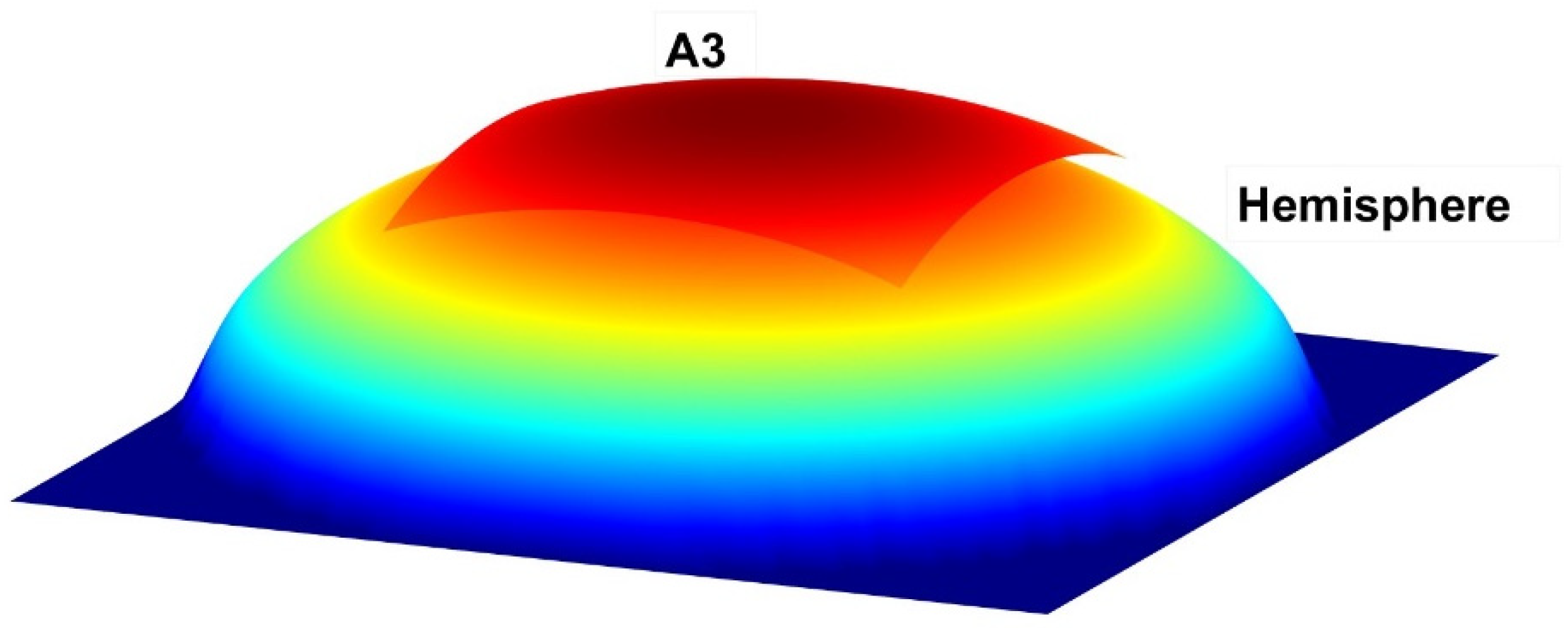
14]: it states that for a spherical surface numbered for convenience A
3, the so-called form factor F
33, in other words, the fraction of energy emitted by such sphere’s fragment over itself, is defined as the ratio between the area of the said fragment and the whole sphere (Equation (1)). Hence, it yields ½ for a hemisphere, ¼ for a quarter of sphere and successively. Due to its simplicity, it constituted a paramount finding [
13,
14,
19,
20].
It can be expressed algebraically as [
13]:
Therefore, this extremely complex factor, if we had to calculate it with conventional methods, equals the area of surface A
3 divided by the total area of the sphere, A
3/A
sphere [
13], as in
Figure 1.
The first Cabeza-Lainez principle is compact and deft in the sense that it avoids the resolution of the difficult canonical expression described in Equation (2) in differential form, regardless of the shape of the spherical fragment [
21], while to find the surface area of the said fragment is almost immediate (
Figure 2).
A complete nomenclature appears at the end of the article. In the meanwhile, for Equation (2),
E1 and
E2 represent the amount of energy (in W/m
2) emitted in Lambertian mode by each surface 1 and 2 [
21].
θ1 and
θ2, stand for the inclination angles formed (in radians) by the perpendiculars to the unit area elements of areas
dA1 and
dA2,
r12 being the random radius vector (in meters) that connects both elementary surfaces
dA1 and
dA2 [
21].
The exact and complete solution of Equation (2) is restricted, after lengthy calculations, to a few spare geometries, such as rectangles and parallel concentric circles [
6]. The author has contributed actively to the list of solved surfaces, as can be seen in references [
9,
22].
Ensuing we will describe how and why the property under study was discovered [
13]. It is known that, in most cases, the fourfold integration of the canonical equation over a volume composed of two curve-edged but planar surfaces, usually circular segments, towards an enclosing fragment of sphere is not attainable. So far, several authors have had to desist after the third round of integration [
6,
23]. Recently, some limited results have been obtained by virtue of numerical calculus and computational graphics [
24,
25]. However, a sphere cannot be discretized in equal elements, and this induces many inconsistencies and flaws in the approximate methods [
24]. On the contrary, as we will demonstrate, Cabeza-Lainez’ derived property is sufficient to solve the problem for all the volumes specified, regardless of the position of the two planar surfaces, i.e., if they cut each other, they are tangent or they have no contact points.
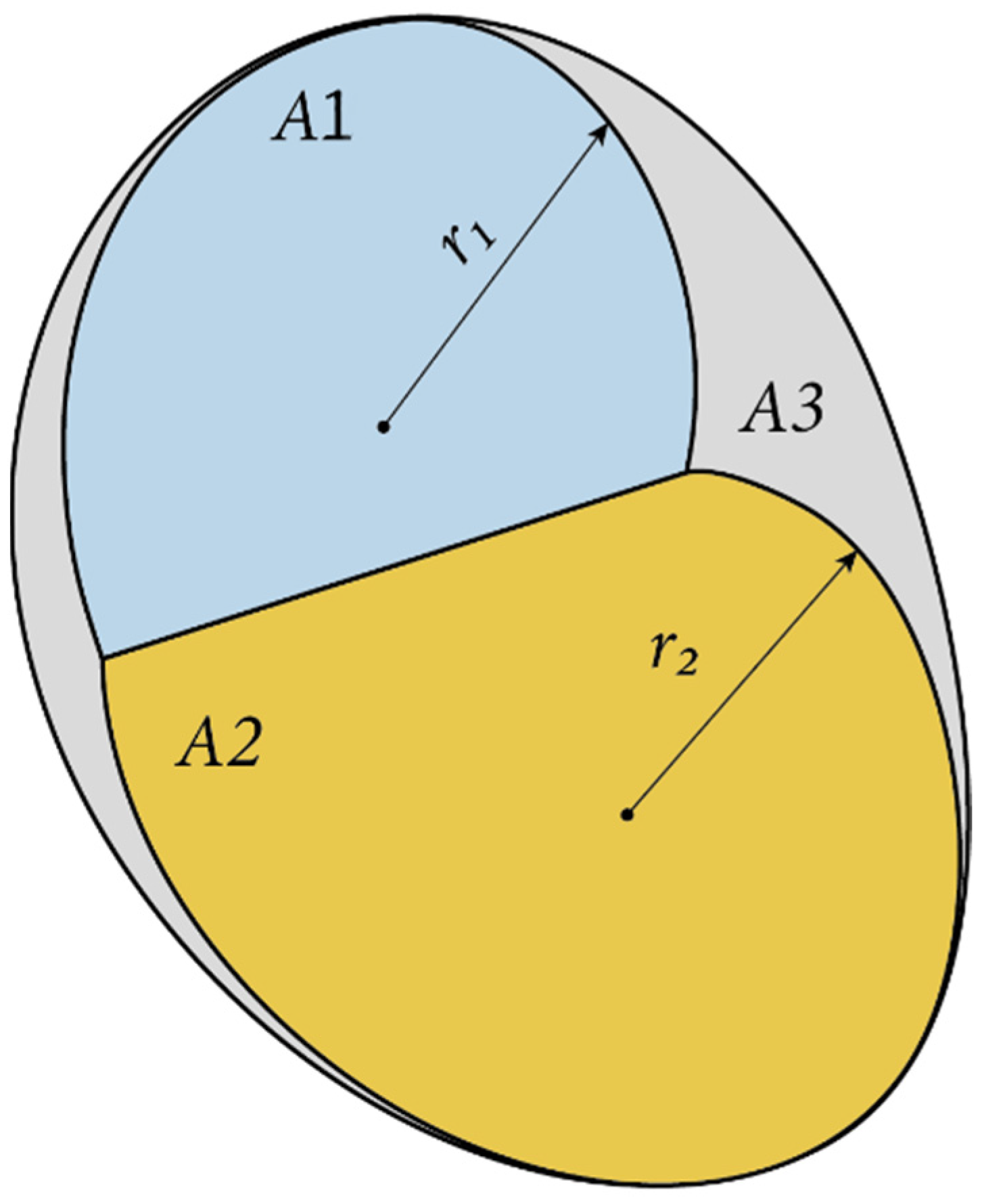
We will express such a new property in the following terms: For any couple of planar sections of a sphere (A
1 − A
2) that enclose within them a fragment of the same sphere (A
3), the form factor from surface 1 to surface 2 can be defined as:
F
33 is the factor of a sphere’s fragment over itself that was defined previously in Cabeza-Lainez’s first principle as the ratio between the area of the said fragment and the whole sphere (Equation (1)), which resulted in a value of ½ for a hemisphere, ¼ for a quarter of sphere and successively. It is written A
3/A
s. Where A
s stands for the total area of the sphere or the constant 4πR
2, and where R is the radius of the said sphere [
13].
A
1 and A
2 are, as described, the respective areas of surfaces 1, 2 (segments of a circle), and A
3 is the comprised fragment of a sphere (
Figure 3 and
Figure 4). Determination of areas 1 and 2 offers no particular problem, but finding the surface of a fragment of a sphere might at times require the employ of spherical trigonometry and the internal angles involved, for instance, through Girard’s theorem, to be able to substitute in the formula of the third property.
The property verifies, irrespective of the relative position of the planar areas A
1 and A
2, if they pass or not through the center of the sphere or even if they possess any tangent point. That is, both planar surfaces can even be independent circular sections of the sphere. The form factors between the sphere and any of the planar surfaces cannot be obtained at present in any other way or procedure, hence the novelty presented. Projective or geometric methods were detained at the inaccessibility of finding the projection of a conical section generated by a sphere on the view cone [
25]; finite element and other numerical procedures encountered the obstacle of non-discretizable surfaces when curves were involved [
26].
Based on this new and innovative principle, obtaining the form factor is only a matter of knowing the areas of surfaces 1, 2 and 3, which is usually trivial, and additionally, it is exact and does not require integration. We have to note that this principle was hinted at by the author in early 2019 [
20], but for several reasons, it was not published until fully developed.
3. Methodology of Proof and Results
In order to demonstrate the validity of the newlyfound property, we will proceed to check it under different instances. Additionally, we will compare it with another principle discovered by the author, the number four principle of radiative exchange, that can be partially applied in some special cases [
13,
14].
The form factor algebra demonstrated elsewhere [
1,
5,
12,
27] states that,
Let us consider a volume composed of threes surfaces in the manner previously described (
Figure 5), a fragment of sphere (surface 3) and two limiting planar surfaces (areas 1 and 2).
Then, the sole reflexive or form factor over the same surface that appears in the calculations is logically F33, which has been previously defined in Cabeza-Lainez’s first principle of form factors (Equation (1)).
It is the ratio between the surface area of the spherical fragment and the total area of the sphere in which surface 3 is contained. F
33 is, therefore, a constant for a given sub-surface pertaining to the total sphere [
22].
In this situation, if we apply the above algebra to find the unknown factors, we will find that,
However, the form factor algebra applied to finite surfaces in a closed volume [
2] implies that:
From Equation (5), we know that
Substituting (9) and (10) in (11)
Additionally, substituting (8) in (12):
Multiplying both terms by A
3, we obtain
Additionally, simplifying,
As Equation (16) is equal to Equation (3), the expression for the new property of the form factors has been demonstrated; Quod Erat Demostrandum or QED (Latin for “which was what we intended to demonstrate”).
Knowing F12, we can immediately find F21 by using reciprocity theorem (8)
Consequently, we have arrived at the values of F23, F13, F32 (9) and F31 (10 and 11), and the exact exchanges between the sphere and the planar limiting surfaces are found.
All the unknown factors of the problem are solved with perfect ease and exactitude for a great variety of shapes previously unexplored.
To ensue, in a manner of comprobation, let us check the form factor due to several typical configurations.
3.1. Perpendicular Circles within the Sphere
We shall begin, as is customary, with perpendicular circles by virtue of Cabeza-Lainez’ 3rd property (
Figure 6 and
Figure 7).
Figure 6 is an extreme case of
Figure 7, in which the perpendicular circles have been enlarged to become tangent in a point.
The third property, that we have seen in Equation (3) states that:
For any couple of planar sections of a sphere (1–2) with a common edge or point, the form factor from surface 1 to surface 2 is in Equation (3).
Additionally, assuming that the area of the circles has to be πR
2/2 and A
1 = A
2, such equation turns out to be:
In this case, A
3 is found by subtraction of the area of the two identical caps of the sphere; the area of one segment is π(a
2 + h
2), h is the height and a the radius of the base circumference of the cap. Theretofore, a = R√2/2 and h = R(1 − √2/2), where R is the radius of the sphere.
and the former yields
Thus, the sought factor F
12 is obtained as
This value appears as the radiative exchange in a sort of cube composed of circles, which in turn are enclosed in a fragment of a sphere. The same value would be obtained for the parallel circles of the same figure or a sort of spherical barrel. In the cuboid made of six squares [
2,
5], the value of F
12 would be, as it is known, 1/5 = 0.2, a very similar quantity which attests to the validity of our calculations. Knowing the F
12 and the F
33 form factors of the problem, the radiant exchanges between the circles and the enclosing sphere, namely, F
23, F
13, F
32 and F
31, are obtained from Equations (5)–(7). This implies a complete novelty even for such simple and usual arrangement of surfaces.
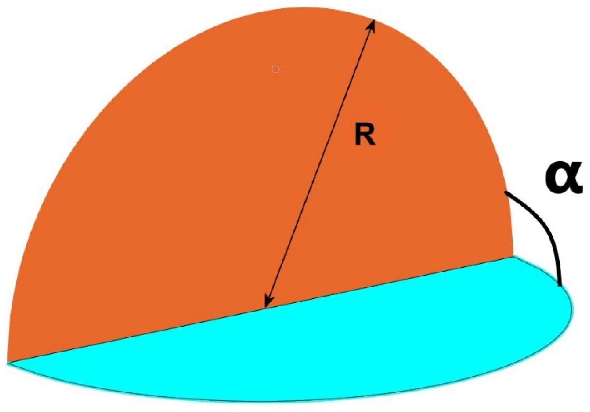
In an additional finding called the fourth principle [
16], by logical deduction from the shape of the sphere, the author was able to obtain the form factor for semicircles of equal radius R possessing a common edge, depending on the internal angle formed by the half disks α. These, together with the consequent factors between the half disks and the sphere [
9], are considered significant contributions so as to be reproduced in technical notes of journals and university catalogues [
13,
22] (
Figure 8).
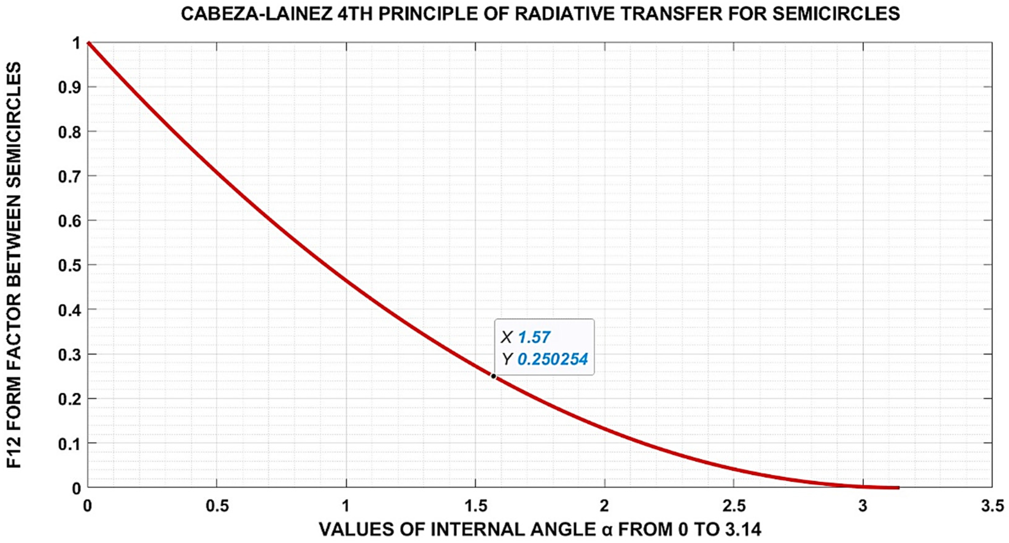
In this case, the defining equation is
Introducing the parameter p,
The equation, represented in
Figure 9 can be expressed as:
The expression of this factor may be seen as somewhat simple, but we need to note that it is impossible to obtain by any other known procedures, for if we were to look at it in more detail (
Figure 10):
The integral equation that we would be forced to solve would be for the semicircles (Equation (25)),
Equation (25), which is only valid for α = π/2, describes the unusual complexity of the factor F
12 to evaluate the radiative exchanges that occur in
Figure 8 and
Figure 10, such exchanges, are unfeasible to calculate in an exact manner even for a perpendicular angle not to mention any other inclinations of the semicircles [
28,
29]. Therefore, the fourth principle can be considered as a pivotal advance, which is now subsumed in the third property, as we will show below. As it happens, the fourth property was discovered before the third property, but being less general, the author has chosen to alter their correlative order.
Let us now proceed to check more examples based on the former finding.
3.2. Calculations for an Eighth of Sphere
The area of a fraction of a sphere is , where α is the angle between two semicircles with a common edge. For the whole sphere α = 2π.
In this case, an octave, α = π/4 and then A3 = πR2/2.
However, we know by virtue of Cabeza’s first principle [
3] that
.
That fraction means the area of the octave of sphere divided by the total area.
Additionally, applying the 3rd principle to this particular case, from Equation (3),
Please be reminded that A1 = A2 = πR2/2 and subsequently both areas are equal to A3, to find the above quantity (Equation (26)).
It is exactly the same result that can be obtained with Cabeza’s fourth principle, given that, in the latter expression we find for α = π/4, the following (Equation (23)),
3.3. Estimations for a Fifth of Sphere
In one fifth of a sphere, the angle α = 2π/5 (72°) and
Using the fourth property instead for the said angle, we obtain,
3.4. The Case of a Fourth of Sphere
If we had applied the same reasoning to a quarter of sphere, we would have arrived to,
Which is already a familiar result of the fourth principle (see
Figure 9 for a 90°).
This value has also been experimentally verified through numerical calculus by Cabeza-Lainez [
30,
31]. It is demonstrated in reference [
1], for the first time, that the value of a form factor between two arbitrary surfaces is the average of the configuration factor (point-by-point) from receiving surface source over the whole emitting surface [
25]. Such demonstration has been used to check the value of 0.25 previously found and other complex cases (see below
Section 3.7).
3.5. Calculations for a Third of Sphere
For a third of sphere, the angle α = 2π/3 and
With the fourth principle we calculated,
It is the same result anew.
3.6. Null Base Case, Half of a Sphere
In the particular case of a hemisphere, Equation (3) provides
As we already knew and expected, since both semicircles are in the same plane and constitute a whole circle, no energy can be exchanged between them since they are like one and the same planar surface [
1].
It is henceforth clear that the third property encompasses all the situations appearing in the more limited fourth property, but both are valid depending on the geometry of the case [
26]. Although other authors approached the radiative transfer due to disks on a point-by-point basis, they did not record any conclusion on form factors and intersecting disks [
28,
29].
3.7. Cases Obtained by Numerical Calculus
As previously mentioned Cabeza-Lainez was capable of integrating the formula for radiative exchange from a semicircle [
18,
20,
31] over a rectangular field in 2013, but it laid dormant until it could be connected with the other properties in 2018 and 2022 (Equation (34)), (
Figure 11).
The meaning of the variables for the spatial directions is given in
Figure 12, r is the radius of the semicircle and x, y, represent the usual Cartesian coordinates in plan.
Equation (34) represents a point-by-point distribution over x and y, stemming from the semicircle, but if, as previously mentioned, it is averaged by numerical calculus over the second emitting source, in an operation performed by mathematical software such as Matlab, the form factor can be obtained with more than sufficient accuracy [
20].
The author has employed this procedure protracting a perpendicular semicircle with the same radius on the plan of the arrangement of the perpendicual semicircle (
Figure 11,
Figure 13 and
Figure 14), to check the value of 0.25 obtained theoretically above in
Section 3.4.
The second demonstration example of the validity of our finding is the form factor between a semicircle and a perpendicular circular segment, both contained in a sphere (
Figure 15 and
Figure 16). The numerical results obtained by Matlab closely agree with those employing the third property of Cabeza-Lainez.
Unfortunately, for shapes not perpendicular, it is not currently possible to arrive at a numerical verification, although we are working consistently on the issue [
21]. Due to the coherence and robust behaviour shown by the third property in all the former instances, we have every reason to believe that it will hold true when an experimental procedure is eventually available for the remaining cases [
23].
4. Complementary Considerations for Inter-Reflections
A first consequence of obtaining the form factors in a volume composed of three surfaces by means of the third principle is that we need to complete the frame with the possibility of inter-reflections between the surfaces involved. This point has also been specifically developed by the author as follows [
13,
31]:
The total balance of energy depends on the equation
where
Edir is the fraction of direct energy and
Eref is the reflected fraction. If these quantities are added, we obtain the global amount of radiation
Etot.
Usually, several surfaces intervene in the process of reflection, and thus a set of expressions can be built. It is possible to introduce a pair of instrumental arrays that we will call
Fd and
Fr. For the volume enclosed by the three surfaces (see
Figure 5), such matrices would have the ensuing form [
32,
33,
34,
35]:
with factors
Fij as previously found, yielding the energy transfer between the respective surfaces involved. Here,
ρi represents the ratio of reflection (direct or otherwise) assigned to a particular element
i [
2,
14].
Notice that in the matrix called
Fd (Equation (36)), the third element of the diagonal is not null as the
Fii factor (with double i) for the same sub-indexes element has definite values for non-planar surfaces as the sphere, unlike the exchange that takes place in a cuboid [
1].
If, after careful calculation by the procedures described in the previous sections, we are able to fix all the elements in Equations (36) and (37), we can establish new expressions (Equations (38)–(40)) in order to correlate the primary direct energy with the one extracted by reflections [
1].
Thus, the problem of radiating energy exchanges in the so-defined volume is completely settled.
The second issue that may appear is that, as the planar surfaces that we have identified are usually the circular bases of caps that belong to the enveloping sphere, instead of finding the exchanges between the circles, we would like to find the exchanges within the said caps [
14].
In this situation, we could resort to the original integration [
2,
5], but we may as well use a new property that we have enunciated, although it was not published before.
We have discovered that in certain cases involving circles, the form factors have a commutative property, a product of form factors which is operational and not only the additive property [
20].
The second principle of Cabeza-Lainez [
13,
30] states that in a volume composed of two surfaces, the form factor exchange is proportional to the ratio of areas between the planar basis and the curved top surfaces [
13,
14]. This principle is valid for forms other than the sphere, but in the case of a spherical cap, as we have here, the form factor depends on the relation between the area of the cap and the area of the base circle.
If we have, for instance, identified the form factor between two inner circles F
12, and then we have the form factor of this circle to the corresponding spherical cap
, the final factor between the more remote circle and the said cap F would be the product of the two factors, that is [
33],
This is a relevant property that has not been identified before to our knowledge, the multiplication of form factor entities and its ensuing algebra. We have checked so far that it only applies to complex forms containing circles in between [
36].
5. Discussion
5.1. Example of Application
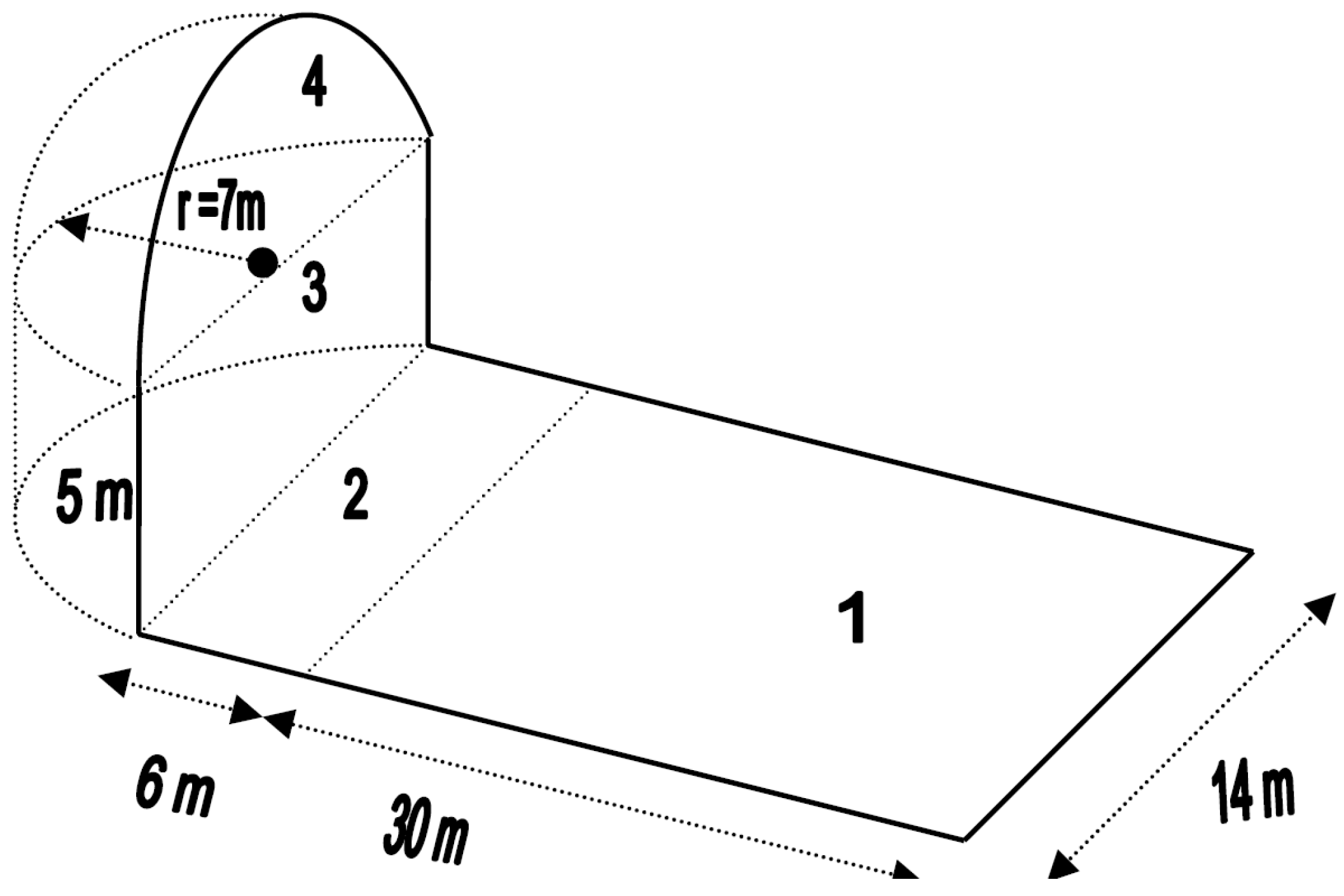
A famous Roman building known as the Scenic Triclinium, located at Hadrian’s Villa in Tivoli (Italy), features a quarter of sphere as a sort of dome (
Figure 17 and
Figure 18).
Following the graphic in
Figure 19, and considering as reflective surface the pool in front of the vault, we use the known properties of form factor algebra to obtain that
In this initial moment, we have equated the arched aperture to a rectangle for the sole purpose of finding the total amount of energy by solar radiation that impinges on this particular surface.
F41 = 0.125705 is the desired value to find the exchange of energy.
For example, on the 21 June, if in the afternoon we consider the solar altitude to be of 50°, according to the weather data of Rome, we find that the value of horizontal illuminance is 74,252 lux. With a set reflectance of the pool of 0.4, we would then receive 29,700.8 lux.
As
F41 = 0.125705, the value of illuminance on surface 4 would be 3733.53 lux, the lower surface of the quarter of sphere as we have just discussed in the fourth principle (
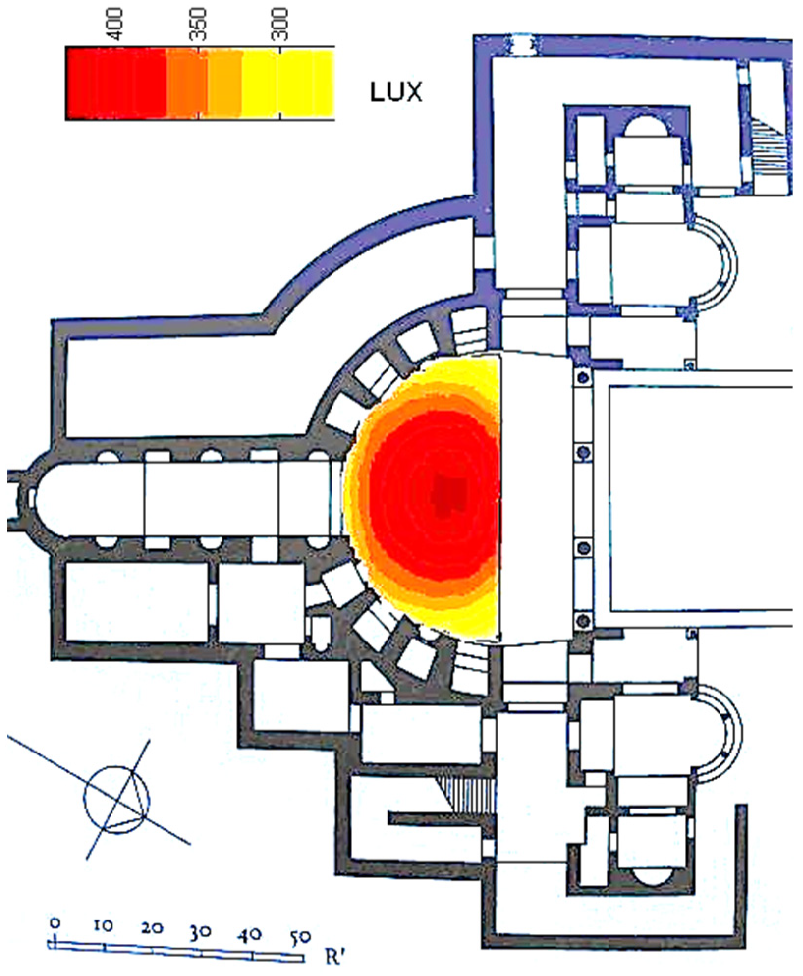
Section 3.4), receives exactly ¼ of the former value, that is: 933.38 lux. Accordingly, the floor plan, by simple operations not presented here, would receive an average of 350 lux (See
Figure 20).
This proves the extraordinary reflective power of the pool, as well as the efficacy of the vault in channelling radiation. Although paradoxically, it is situated to the Northwest of the Triclinium, it has an exposure to the sun appropriate for cooling.
We have just shown with “conservative” figures that the upper clerestory of the building alone produces more than 300 lux on the floor plan. To be on the safe side, we did not take into account the illuminance from the lower portico because today, we are unsure about the obstructions that this element would have presented to the light.
It is said that the dome in its heyday was covered with bright enameled tiles, and that could have added a great amount to the former value of illuminance. With the findings described in previous sections of the article, we could discuss the probable amount of internal reflections involved. On the other hand, the building is roughly oriented to the North and protected by an artificial hill, so direct radiation rarely gets into the halls. However, by virtue of the pool and dome described, the spaces have adequate daylight avoiding the heat at the same time. There is no doubt that the Roman builders had intuitively noticed this effect and used it for special buildings such as the Triclinium. If we add the patent effect of earth-coupling and that of water running around the floor and walls of the structure in nymphaea, it is hard to imagine an architectural icon more exquisitely integrated with its surroundings. This ancient vault is undoubtedly an outstanding example of sustainable design.
5.2. Recollection on the Findings
Thus far, we have established and verified a new unbeknownst property to determine:
The total exchanges of radiant energy between two planar surfaces that cut a sphere in any way and the comprising fragment of the same sphere. The said planar surfaces can intersect, be tangent or stay completely independent of one another. The exchange case for arbitrary intersections and of these with the fragment of the sphere is an absolute novelty which cannot be obtained by any other procedure. The remaining non-intersecting layout is perfectly encompassed under a modern and inclusive formulation, and the exchanges between the disks and the inner sphere are completely innovative.
The possible inter-reflections of the compound despite the existence of a curved surface. This was not previously solved in the references since reflections were always limited to cuboidal spaces.
The introduction of the commutative property and its subsequent algebra in form factors on a purely surface-to-surface basis for volumes that integrate the circle in their composition.
Thus, the property enunciated is original and quite efficient, a few cases covered by it, for instance, radiating parallel circles, were partially addressed earlier in the literature by other clumsier means, usually involving lengthy integrations [
36,
37]. These limited cases had absolutely no regard for the radiative transfer between the circles and the surrounding fragment of a sphere that we have now settled in an exact manner [
38]. Particularly, if the two planar surfaces intersect themselves in any fashion and cease to be entirely circular to become circular segments, then such relevant stance was ignored by the literature [
11] or was termed unsolvable [
6], and we have proved that it can only be determined through the third property of Cabeza-Lainez, hereby presented.
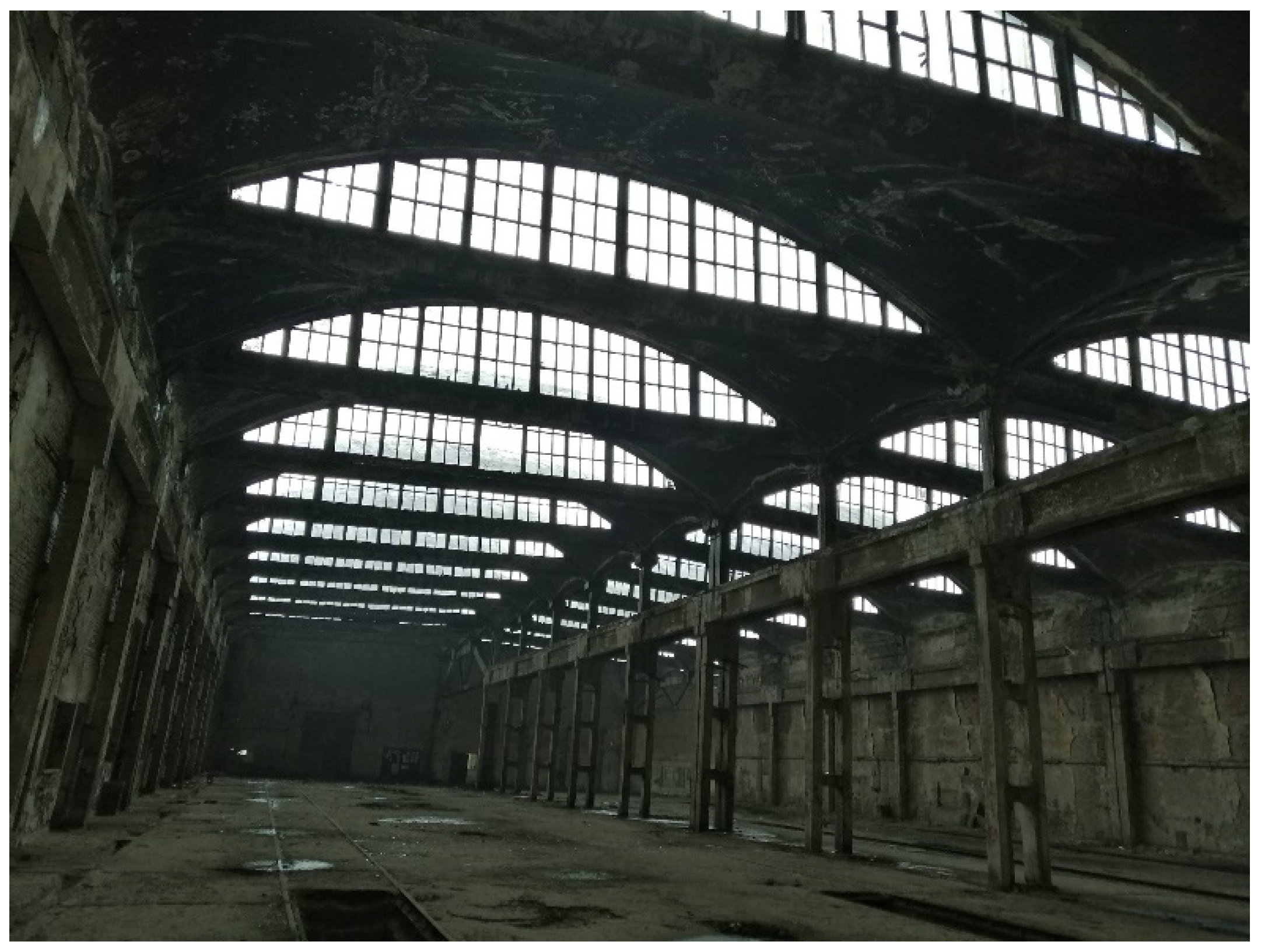
Such findings will have paramount repercussions in various fields of engineering and heat transfer simulations that are not completely foreseeable at the moment, but we can outline just a few in building construction or heritage retrofit and surely in the lighting and aero-spatial fields. Sundry architectural configurations, as we have seen in the example of
Section 5.1, feature the sphere and the circular fragment as an important part of their fenestration or ceiling system (
Figure 21,
Figure 22 and
Figure 23), especially as we mentioned for monumental or singular buildings. The analysis of the thermal, lighting or even acoustic performance of these features was severely restricted, and the possibility of increasing energy savings and comfort for the users was almost impeded, which subsequently led to its abandonment. With the findings developed, we expect that they will become better preserved and future enhancements will turn mandatory for this field of knowledge [
30].
In aerospace techniques, parts of the vessels or mechanisms that feature spheres and/or circles will experience a more accurate prediction of their performance and capabilities thanks to this property introduced in computational geometry. Lighting industries will surely benefit from the display of an ampler palette of algorithms and simulation tools in order to be able to offer more conscious products [
39]. This is our expectation for beyond the manuscript.


