Article

Experimental Study on Flexural Behavior of RC–UHPC Slabs with EPS Lightweight Concrete Core

Faculty of Building and Industrial Construction, Hanoi University of Civil Engineering, 55 Giai Phong, Hai Ba Trung, Hanoi 100000, Vietnam
*
Author to whom correspondence should be addressed.
Buildings 2023, 13(6), 1372; https://doi.org/10.3390/buildings13061372
Submission received: 13 April 2023 / Revised: 16 May 2023 / Accepted: 22 May 2023 / Published: 24 May 2023
(This article belongs to the Special Issue Machine Learning Applications in Sustainable Buildings)

Abstract

:
This paper presents an experimental investigation that focuses on the flexural behavior of an innovative reinforced concrete–ultra-high performance concrete slab with an expanded polystyrene lightweight concrete core. This type of slab is proposed to serve the semi-precast solution, in which the bottom layer is ultra-high performance concrete working as a formwork during the construction of semi-precast slab, the expanded polystyrene lightweight concrete layer is used for the reduction of structure self-weight, and the top layer is normal concrete designed to withstand compressive stress when the slab is loaded. Two similar large-scale specimens with dimensions of 6200 mm × 1000 mm × 210 mm were fabricated and tested under four-point bending conditions to investigate the flexural behavior of composite slab. Test results indicated that three different layers of materials can work effectively together without separation. The bottom ultra-high performance concrete layer leads to the high ductility of the slab and has a good effect in limiting the widening of the crack width by forming other cracks. According to design code ACI 544.4R, a modified distribution stress diagram on the composite section was proposed and proven to be suitable for the prediction of flexural strength of the composite section with an error of 3.4% compared to the experimental result. The effect of the ultra-high performance concrete layer on the flexural strength of the composite slab was clearly demonstrated, and for the case in this study, the ultra-high performance concrete layer improves the flexural strength of the slab by about 11.5%.

1. Introduction

Reinforced concrete (RC) is the most commonly used material for construction worldwide. Formwork made from wood or steel has the temporary function of shaping and fixing fresh concrete to fabricate RC members and structures, which is removed when concrete hardens. The processes of installing and removing the temporary formwork create a considerable amount of solid waste at the construction site and spend significant resources in terms of construction cost and time Therefore, precast RC has attracted much attention from researchers investigating and developing methods of recuing construction waste, shortening construction time, and decreasing construction cost effectively, with the aim of sustainable construction [1]. Many studies have analyzed the cost and time advantages of precast concrete construction systems compared to conventional construction and reported that up to 40% of cost and time can be saved by appropriate planning and implementation in precast constructions [2,3]. As an inevitable consequence, the research and development of precast concrete structures has increased rapidly in the past few decades [1,4,5,6]. A semi-precast reinforced concrete slab, as an innovative precast concrete member, comprises a bottom precast RC layer (precast plank) and a cast in situ concrete topping. Problems with concrete topping and continuous reinforcement between the slab unit and the supporting component have been well described and considered through numerical and experimental modeling in a recent study [7]. The contact surface between the layers is usually roughened to enhance the bonding between different material layers. In addition, in some cases, inclined steel truss bars have penetrated the interface to stiffen the precast plank as well as improve the composite action of the entire slab [8]. With this type of slab structure, the bottom precast plank is used as the formwork during the fabrication of such semi-precast structures. Therefore, the cost of formwork can be minimized. Deng et al. [9] synthesized other investigations [8,10,11,12,13] and showed that the precast RC composite slab with inclined steel truss bars acquires beneficial features of both precast and RC slabs cast in situ, containing high construction efficiency and cost savings, high integrity, high reliability, and comparable mechanical behavior to that of popular slabs cast in situ. These studies also pointed out that the inclined steel truss bars have an insignificant impact on the load-carrying capacity but can greatly improve the ductility of the RC composite slab. The influences of different steel truss bars and innovative joint configurations on the flexural bending tests of composite slabs have been examined [11,13].
The self-weight of the structural floor system accounts for a large proportion of the total dead load in reinforced concrete buildings [14]. The self-weight of floor structural slabs typically possesses approximately 40–60% of the entire structure mass, according to a simple calculation for loads of a residential high-rise building, and a 10% reduction in slab self-weight can lead to a 5% reduction in total building self-weight [15]. The lighter self-weight of the structural slab reduces seismic response, resulting in lower bearing capacity demands for main structural components such as shear walls, columns, and beams [16]. The lightweight slab could make lifting and installation easier during precast concrete slab construction, resulting in significant cost savings and accident reduction [17,18,19]. Moreover, the semi-precast concrete slab is prone to cracking during the lifting and installation process because of the low tensile strength of normal concrete, leading to the low durability concern of the structure during service. Thus, a solution for a lightweight semi-precast composite slab with high cracking resistance and tensile bearing capacity is necessary.
Concerning the idea of combining lightweightness and high tensile performance of precast plank, an innovative reinforced concrete-ultra high-performance concrete (RC–UHPC) slab with expanded polystyrene (EPS) lightweight concrete core (so-called RC–UHPC composite slab) is proposed to serve the semi-precast solution. For this type of composite slab, the bottom layer of ultra-high-performance concrete (UHPC) with an inclined steel truss bars system works as a formwork during the construction of a semi-precast slab, the EPS lightweight concrete layer is used for the reduction of structure self-weight, and the top layer is normal concrete designed to withstand compressive stress when the slab is loaded. UHPC has high compressive (up to 150 MPa) and especially tensile strengths (up to 15 MPa), which are much higher than normal concrete. The high density and compactness of the UHPC matrix lead to great physical performance as low permeability can restrain the access of negative substances, leading to enhanced durability [20,21]. UHPC also exhibits other outstanding characteristics including high energy dissipation, fracture energy (up to 40 kJ/m2), and ductility [22]. An additional interesting characteristic is the strain-hardening performance of UHPC in tension owing to the presence of steel fibers [23]. Considering the excellent physical and mechanical performance of UHPC, this material is used for the proposed RC–UHPC composite slab, as several previous studies have successfully implemented [24,25]. For the lightweight infill material of the slab, expanded polystyrene (EPS) lightweight concrete that has been utilized for several decades to reduce the structural weight is adopted. Besides reducing the structure’s self-weight, EPS concrete also revealed good functional uses such as sound and thermal insulation [26].
For the application of the proposed RC–UHPC composite slab in practice, several related issues need to be investigated, in which two important issues are as follows: (i) the ability to work effectively together as a composite slab (composite action) considering the different fabrication time of different material layers; and (ii) the load carrying capacity of the entire composite slab and how to design this type of slab. The former will be solved by the design of inclined truss bars in a future work, while the latter is investigated in this study. For this purpose, two large-scale specimens with the same dimensions of 6200 × 1000 × 210 mm were fabricated and tested according to a four-point bending scheme to investigate the flexural behavior of the proposed RC–UHPC composite slab. According to design code ACI 544.4R, a modified distribution stress diagram on RC–UHPC composite section was also proposed and proven to be suitable for the prediction of the flexural strength of the RC–UHPC composite section.

2. Experimental Program

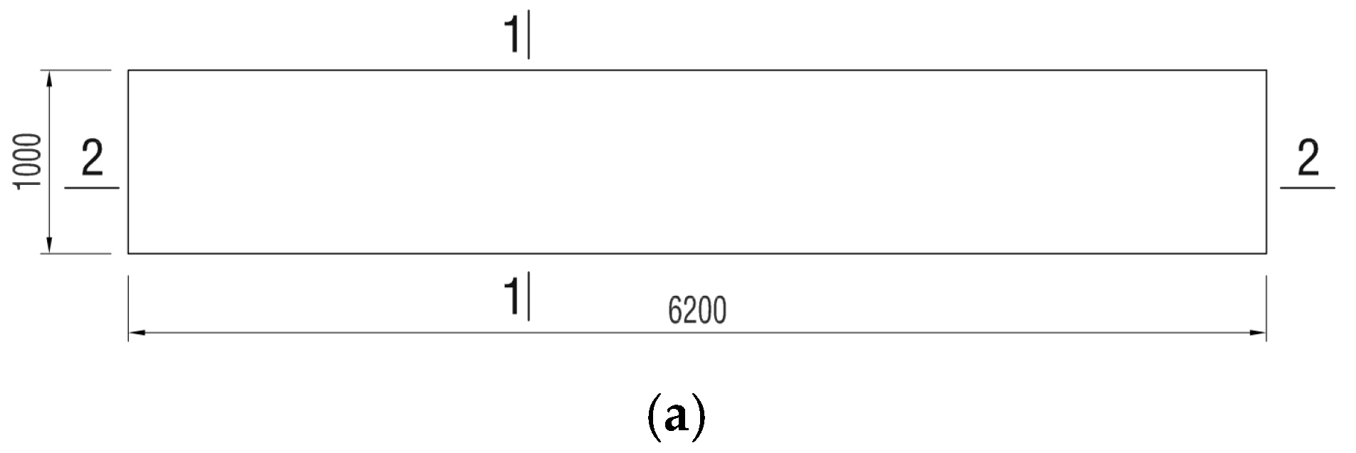
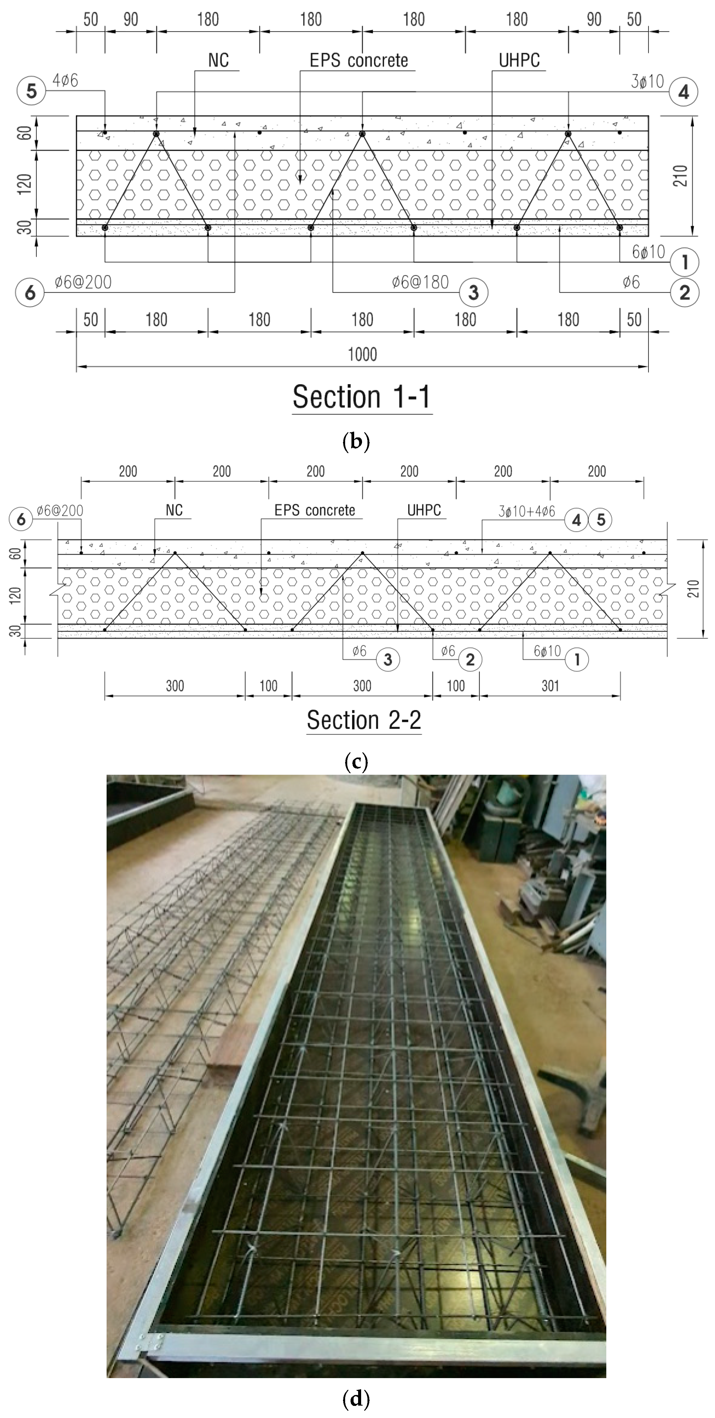
2.1. Specimen Dimensions

Two specimens—namely, M1 and M2—were designed to investigate the flexural behavior of the proposed RC–UHPC composite slabs with EPS lightweight concrete cores (so-called RC–UHPC composite slabs). The specimens have the same rectangular cross-section with the dimension of 6200 × 1000 × 210 mm. This is the actual size of the slab plate that will be used in the semi-precast slab structure. The cross-sectional thickness of RC–UHPC slabs consist of 3 different layers of materials. The bottom layer is UHPC with a thickness of 30 mm, the middle layer is expanded polystyrene (EPS) lightweight concrete with a thickness of 120 mm, and the top layer is normal concrete (NC) with a thickness of 60 mm. These thicknesses of material layers were designed with minimum UHPC layer thickness and maximum EPS lightweight concrete layer thickness to minimize the cost and self-weight of the slab structure.
For the purposes of using the bottom layer of UHPC as formwork during the construction of the semi-precast slab, the lightweight concrete layer for the reduction of structure self-weight, and the top layer of normal concrete for the subjection of compressive stress when the slabs are bearing, the reinforcement of RC–UHPC composite slab includes three main components: the bottom mesh, the inclined transverse reinforcements, and the top mesh. The bottom mesh consists of the main longitudinal rebars of 10 mm diameter, with a spacing of 180 mm and distribution rebars of 6 mm diameter. This mesh is embedded in the UHPC layer with a cover layer of 10 mm. The inclined transverse reinforcements with a diameter of 6 mm are used not only to connect the UHPC and NC layers but also to serve the lifting process of the UHPC bottom plate during the construction of the semi-precast slab. The top mesh consists of three main longitudinal rebars with a diameter of 10 mm, which directly connect to the inclined reinforcements and the additional distribution rebars of 6 mm diameter in both directions to form a reinforcing mesh that meets constructive requirements. This mesh is embedded in the NC layer with a cover layer of 20 mm. The dimensions and reinforcement details of the test specimens are illustrated in Figure 1.

2.2. Materials

The raw materials of UHPC consist of quartz sand with an average diameter of 300 μm, cement Type I, silica fume (SF) with an average diameter of 0.15 μm, steel fiber with a volume fraction of 1%, and polycarboxylate-based superplasticizer (SP) additive. The composition of raw materials for 1 m3 of UHPC mixture is listed in Table 1, and the physical and mechanical properties of steel fiber are shown in Table 2.
The mix proportion of normal concrete was designed to obtain concrete with a compressive strength of around 35 MPa, as shown in Table 3.
The EPS concrete used expanded polystyrene beads with the size of 3–4 mm and Sikament R4 plasticizer as an additive. The mix proportion of EPS concrete was designed to obtain concrete with a density of about 1200 kg/m3, as shown in Table 4.
The mechanical properties of concrete materials were determined from the test results of specimens according to ASTM standards after 28-day curing age. For compressive strength of each concrete type, three cylindrical specimens with the size of 100 mm × 200 mm were prepared and tested according to ASTM C39M [27], while three cylindrical specimens with the same size were prepared and tested according to ASTM C469M [28] for the elastic modulus. The compressive strength and elastic modulus of each concrete type were taken as the average value of three values from the corresponding tests. As a result, the UHPC has a compressive strength of fck,UHPC = 123.7 MPa and an elastic modulus of EUHPC = 42.5 GPa; the NC has a compressive strength of fck = 34.66 MPa and an elastic modulus of ENC = 33.20 GPa; and the EPS concrete has a compressive strength of fck,EPS = 3.68 MPa and an elastic modulus of EEPS = 3.35 GPa. The density of UHPC, normal concrete, and EPS concrete were also measured to be 2645 kg/m3, 2340 kg/m3, and 1180 kg/m3, respectively. Longitudinal, inclined, and transverse reinforcements of the PC-UHPC slab specimens consist of two types of rebars with diameters of 10 mm and 6 mm that have yielding strengths of 420.7 MPa and 315.5 MPa. The UHPC tensile strength test was not conducted for the batch that was used to fabricate the RC–UHPC specimen due to the limited testing conditions at that time. However, the tensile strength test of the same UHPC mix proportion with another batch had been conducted before. Figure 2 shows the stress–strain curves obtained from the axial tensile test of 3 dog bone-shaped UHPC specimens with the same cross-section of 25 × 50 mm and a gauge length of 175 mm. The average tensile strength of the UHPC from the three tests is 8.37 MPa.

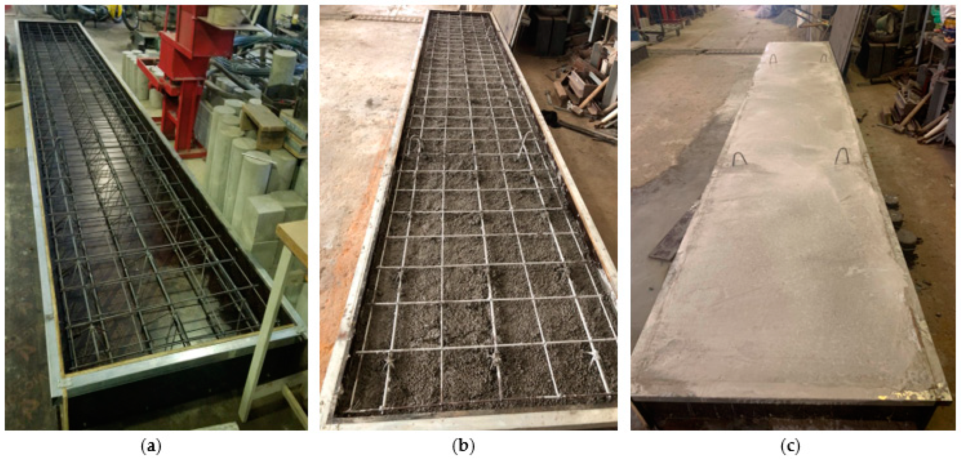
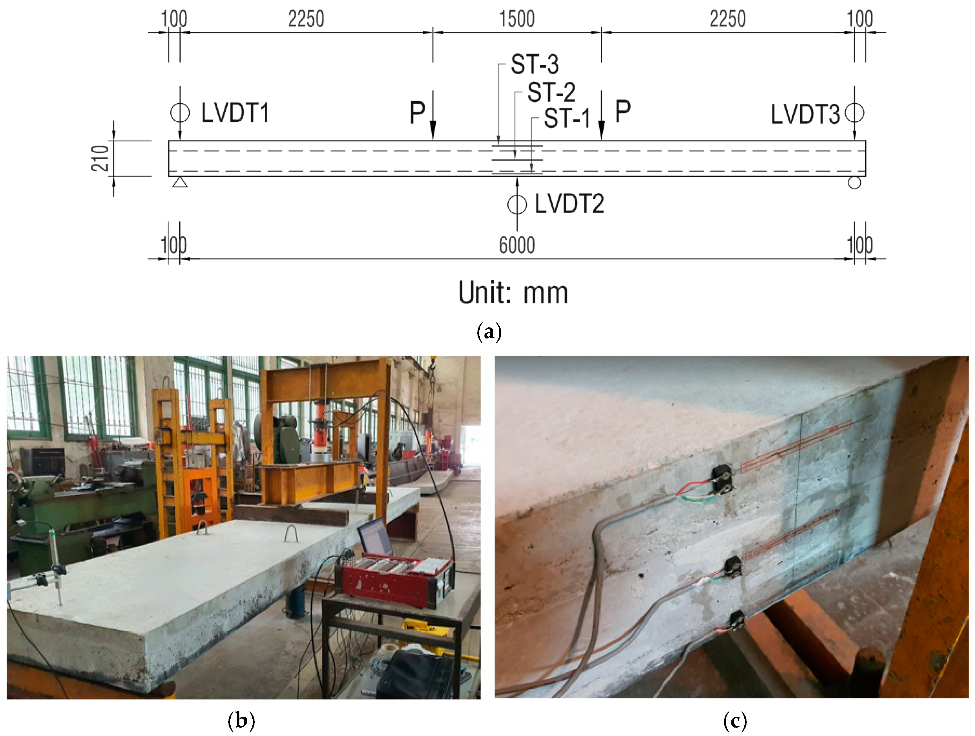
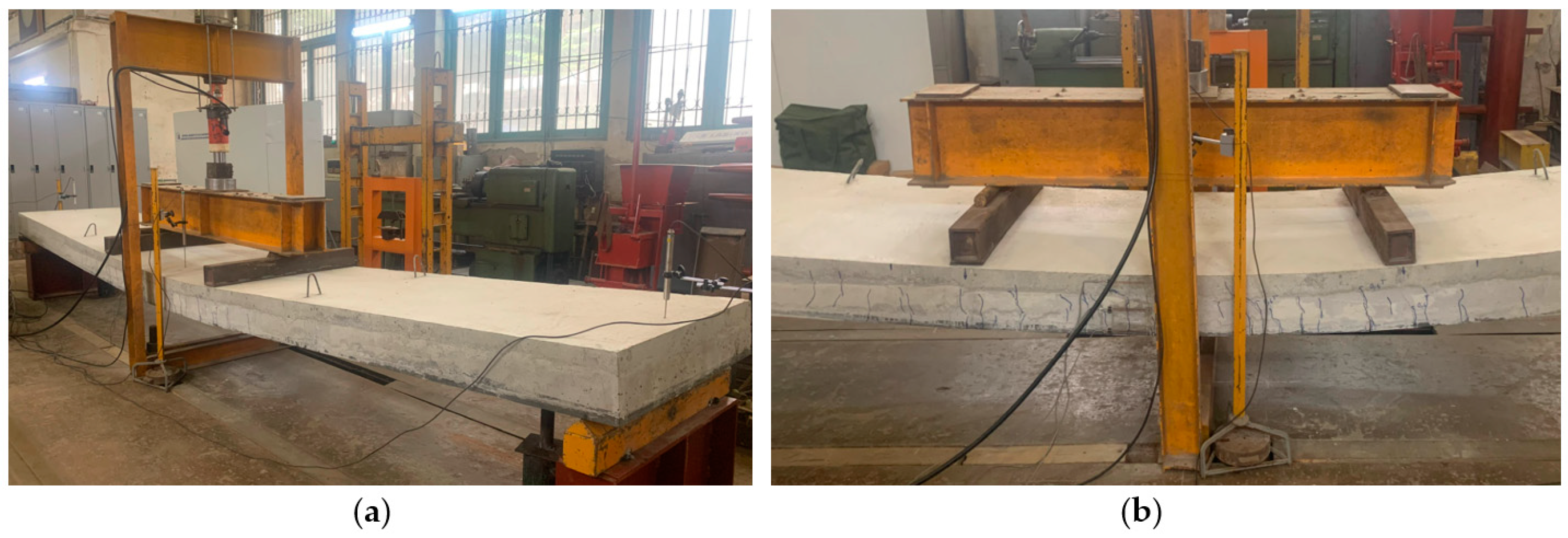
2.3. RC–UHPC Specimen Preparation and Test Setup

All materials were prepared and the RC–UHPC specimens were fabricated in the laboratory. High-quality wood formworks were utilized and the reinforcement diagram, which was separately tied, was installed into the formworks first. Each concrete type was thoroughly mixed in compliance with specifications and then poured into the formwork with design thicknesses in the order of UHPC, EPS, and normal concrete from the bottom up. After fabrication, two specimens were cured at room temperature and humidity for 28 days until testing. The processes for the fabrication of RC–UHPC composite specimens are shown in Figure 3.
The bending behavior of the specimens was investigated by a four-point bending test under monotonic loading. The 6200 mm length specimen was placed on two simple supports with a clear span of 6000 mm; one end is hinged support and the other end is roller support with a distance of 100 mm from the edges of the test specimen. Two symmetrical concentrated loads at a distance of 2250 mm from the nearest support were applied to the test specimens through two steel spreader beams placed above to distribute the load to the test specimens, leading to the length of a maximum bending moment of 1500 mm. The loads were generated by a servo-hydraulic actuator with the maximal measuring range of 1000 kN. During the experiment, the applied load was measured by a load cell. The mid-span vertical displacement at each applied load level was measured by installing three linear variable displacement transducers (LVDTs). Two displacement transducers (LVDT1 and LVDT3) were attached to the supports, while the LVDT2 was installed at the mid-span of the specimen. The mid-span vertical displacement value is determined by δ = δ2 − 0.5 (δ1 + δ3), where δ1, δ2, and δ3 are the values measured from LVDT1, LVDT2, and LVDT3, respectively. Three electronic strain gauges ST-1, ST-2, and ST-3 were also arranged at the middle of UHPC, EPS, and normal concrete layer, respectively, with the location at the mid-span of the specimen. The measurement data was automatically recorded via a computer and a data logger which are connected to all LVDTs and electronic strain gauges. The testing arrangement and measuring equipment installation are shown in Figure 4.
The testing procedure is as follows. The specimen is first loaded to 40% of the estimated cracking load to inspect the loading and measuring systems, as well as to eliminate inelastic deformation. The preloading process, including loading and unloading, will not stop until displacement and strain are kept approximately stable. The load is then applied to the specimen slowly and continuously until the ultimate load is reached. During the test, the formation and development of cracks on the specimen surface are measured and drawn.

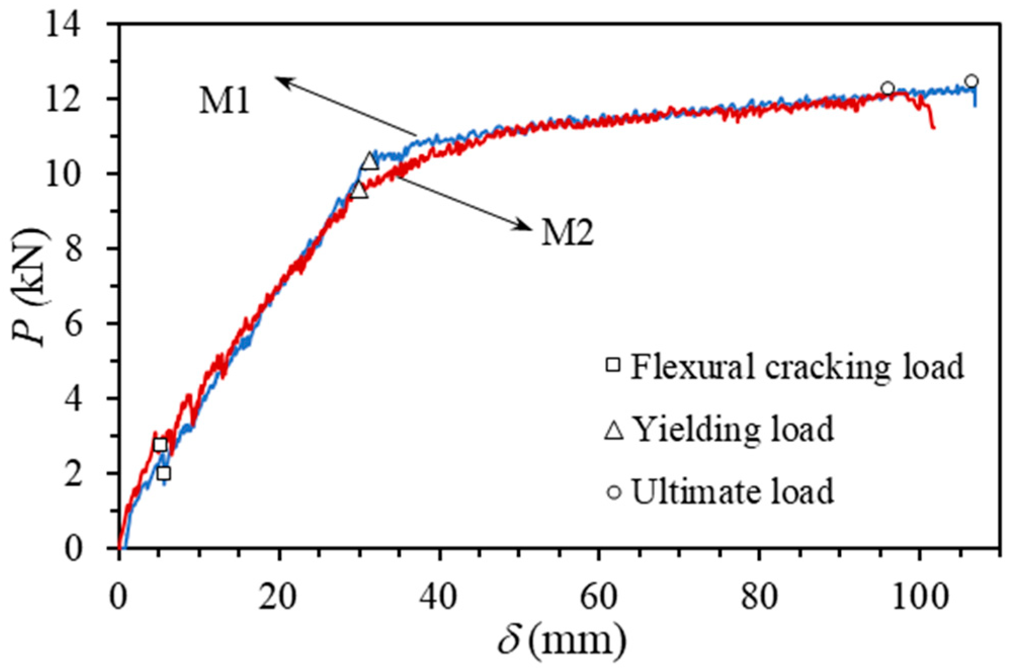
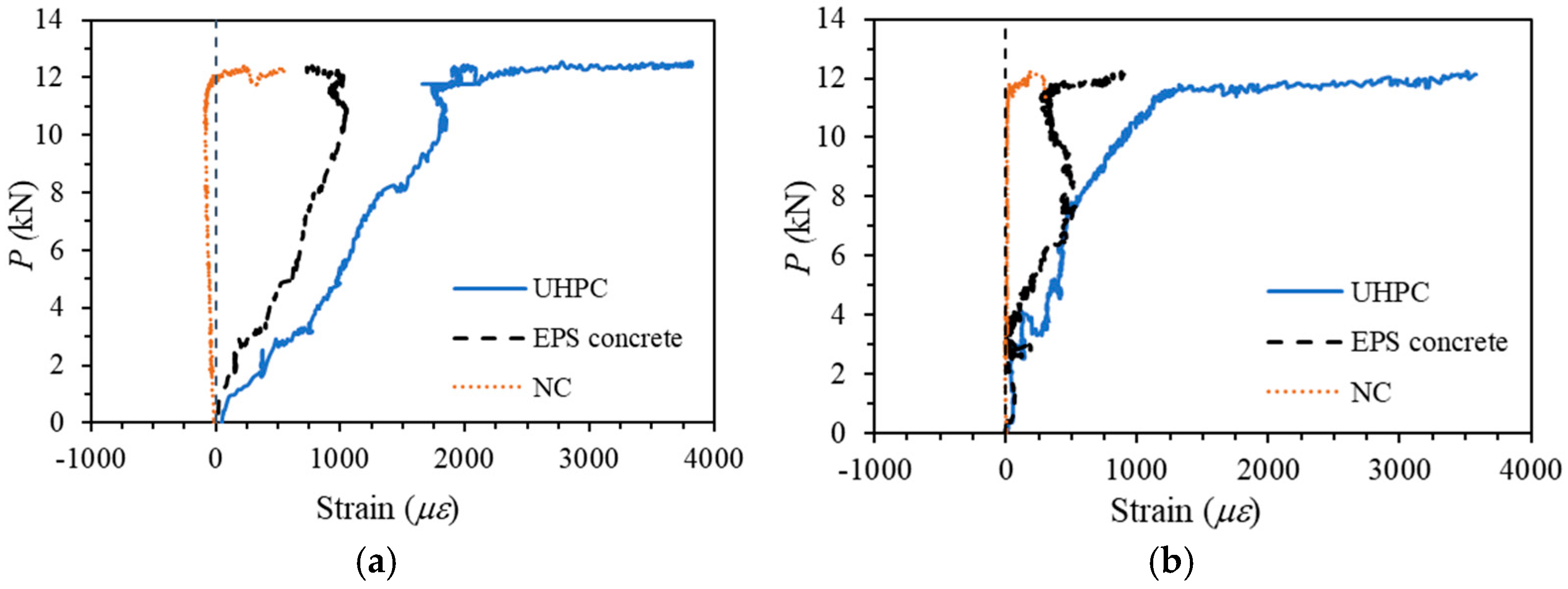
3. Experimental Results and Discussions

Two specimens of RC–UHPC composite slabs were tested to failure. Both specimens displayed a typical flexural failure mode, as demonstrated by the distinct ductile plateau before failure. No typical shear cracks were observed in the shear regions of the specimens. The first flexural cracks appeared at the bottom near the middle of the span where the largest tensile stress was greatest. The widths of the diagonal cracks were somewhat bigger than those of the bending cracks in the early loading process. As the load increased, more cracks appeared with quite equal spacing in the middle of the slab span, and these cracks developed deep into the section in an upward direction. At the failure of the test specimens, there were about 22 visible large cracks distributed relatively evenly within 2.5 m in the middle of the slab. These cracks developed continuously, few of them were interrupted, and some of the largest cracks had grown into the normal concrete layer. No separation of different concrete layers was observed during the test. These results indicate that the UHPC layer has a good effect in limiting the widening of the crack width by forming other cracks, unlike normal concrete, as shown in the literature [1,29]. In addition, the bonding between the concrete layers is very good, allowing different layers of materials to work simultaneously. However, this issue needs to be further studied when the layers of material are poured at different times. In summary, ductile flexural failure occurred in both specimens without concrete crushing in the compression zone. The typical failure mode and crack distribution of the RC–UHPC composite slab specimen are shown in Figure 5.
Figure 6 shows the applied load versus mid-span deflection relationships for both specimens, M1 and M2. In this figure, the flexural cracking, yielding, and ultimate points are also plotted, while the corresponding load values at these stages are listed in Table 5. As can be seen in Figure 6, the load–deflection curves of the two specimens display the same pattern. A linear relationship is observed before the crack occurs and the curves almost keep linear after that, with only a slight decrease in stiffness. When the longitudinal reinforcement yields, the stiffness of both specimens drops with a long ductile plateau stage before failure. The high ductility of specimens exhibited over the long ductile plateau stage in the case of a rather low longitudinal reinforcement ratio of 0.24% is attributed to the UHPC layer as indicated in literature [30].
The relationships between the applied load and strain at the middle of each concrete layer at the mid-span section of specimens M1 and M2 are shown in Figure 7, in which the positive value denotes the tensile strain, while the negative value characterizes the compressive strain. As seen in this figure, the measured results have some abnormality; it is possible that the strain gauges are only installed on one side of the test specimens, resulting in uncertain measurement results. However, the similar results of the tensile strain at the middle of the UHPC layer from two specimens indicate that the measured strain from ST-3 may be reliable. Based on these measured results, the large tensile strain in the middle of the UHPC layer of about 4000 με demonstrates, once again, the effect of this layer on the ductility of the RC–UHPC composite slabs.

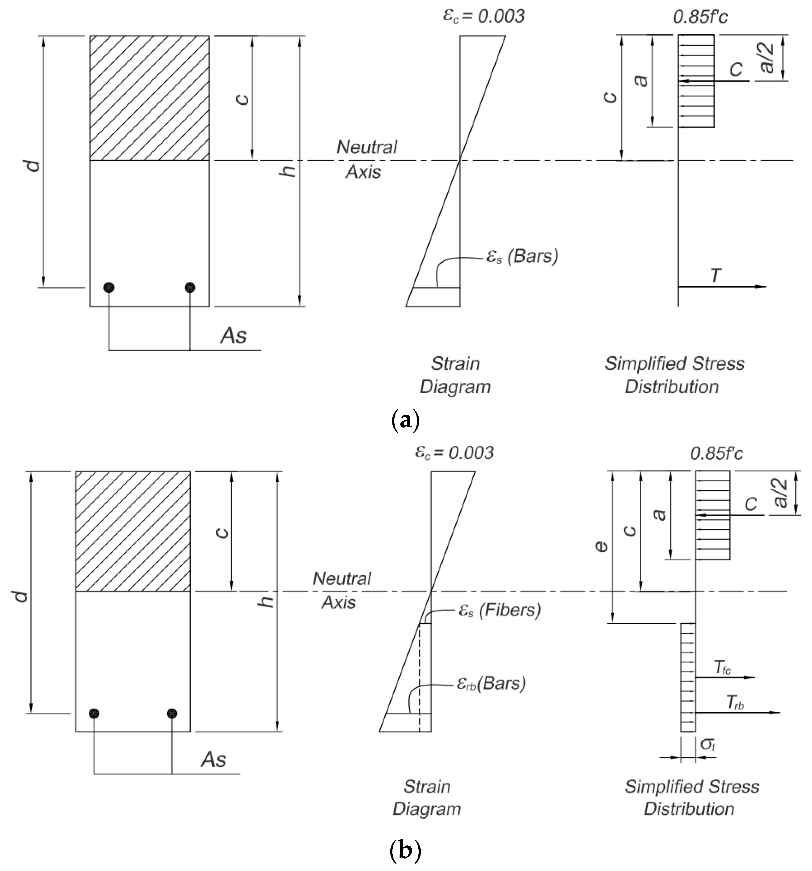
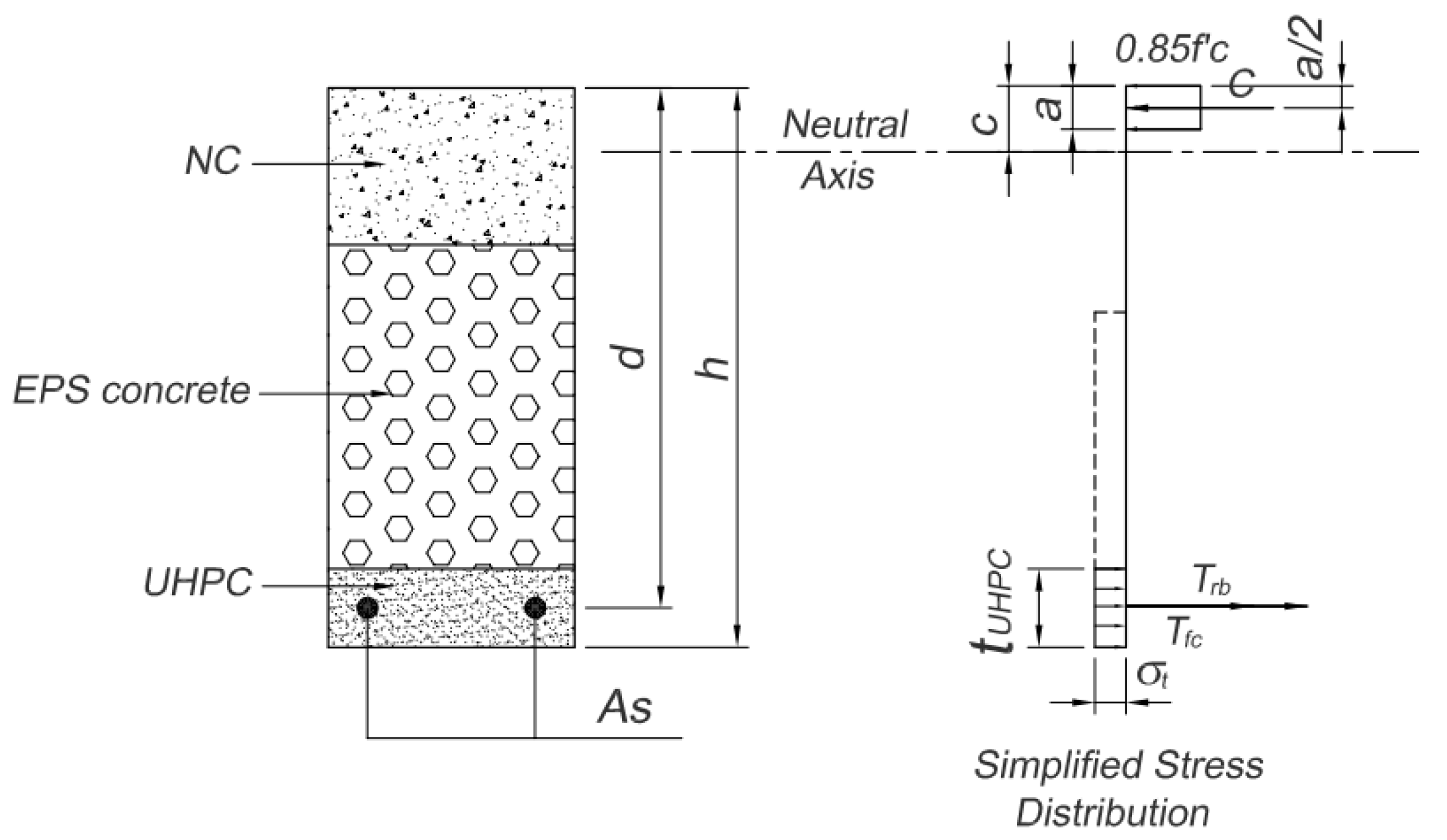
4. Flexural Strength of RC–UHPC Composite Section

According to the test results, the flexural strength of the RC–UHPC composite section can be determined using the following equation:
M = P l 1 + s w 8 L 2
where l1 is the distance from the load position P to the nearest support in Figure 4 (l1 = 2.25 m); L is the span of the test specimen (L = 6.0 m); and sw is the self-weight uniformly distributed over the length of the specimen. From the measured density of each material layer in the RC–UHPC composite slab and the obtained ultimate load, the flexural strength of the RC–UHPC composite section was calculated to be 44.01 kN·m and 43.66 kN·m for M1 and M2 specimens, respectively.
The current design codes do not mention the bearing capacity of flexural members with the composite cross-section as in this study; they only refer to the calculation of the reinforced concrete or reinforced UHPC cross-section; for example, the ACI codes system. In this study, the ACI codes are used to predict the flexural strength of the RC–UHPC composite section to check whether these standards are suitable for determining the flexural capacity of composite cross-sections. Current design code ACI 318 [31] uses the strain diagram and simplified stress distribution as presented in Figure 8a and implies that the flexural strength of reinforced concrete section can be computed by the following:
M n = A s f y ( d a 2 )
In Equation (2), a is the depth of the rectangular stress block that can be determined as a = β1c, where β1 is the stress block parameter and c is the neutral axis depth. For compressive strength of concrete between 17 and 28 MPa, β1 = 0.85, β1 shall be reduced linearly with a rate of 0.05 for every 7 MPa of compressive strength of concrete above 28 MPa, and the smallest value of β1 is 0.65. As can be seen in this equation and Figure 8, the ACI 318 design code [31] neglects the capacity of concrete in the tensile zone. However, for a steel fiber reinforced concrete section or composite section with a layer of steel fiber concrete in the tensile zone, the effect of steel fiber should be considered. For flexural strength of the steel fiber-reinforced concrete section, the ACI 544.4R code [32] adopts the strain diagram and simplified stress distribution as presented in Figure 8b and provides the flexural strength equations as follows:
M n = A s f y ( d a 2 ) + σ t b ( h e ) ( h 2 + e 2 a 2 )
where,
  • Mn is the nominal flexural strength of the section;
  • fy is the yield strength of steel rebar;
  • d is the effective depth of the section;
  • a is the depth of stress block;
  • b is the width of the section;
  • h is the height of the section;
  • e = [εs(fibers) + 0.003] c/0.003 where εs(fiber) = σf/Es;
  • c is the neutral axis depth;
and σt is the tensile stress in fibrous concrete, which can be calculated as follows:
σ t = 0.00772 l f d f ρ t F b e
where lf is the length of steel fiber; df is the diameter of steel fiber; ρf is the percent by volume of steel fiber; and Fbe is the bond efficiency factor which varies from 1.0 to 1.2 depending upon fiber characteristics. Thus, the effect of steel fiber in the tensile zone is considered through the tensile force of fibrous concrete, which is as follows:
T f c = σ t b ( h e )
With the RC–UHPC composite slab proposed in this study, the thickness of normal concrete is always designed to adequately carry the compressive force when the cross-section is in the limit state. The effect of EPS concrete on the flexural strength of the section can be neglected due to its very low strength in both compression and tension. Therefore, if the tensile strength of the UHPC layer is not taken into account, the flexural strength of the composite section can be calculated as the normal reinforced concrete section according to ACI 318 [31] by using Equation (2). In case the effect of steel fiber in the tensile zone is considered, meaning that the tensile strength of the UHPC layer is taken into account, the stress distribution on the RC–UHPC composite section can be simplified as shown in Figure 9. In this model, the tensile stress is uniformly distributed in the whole thickness of the UHPC layer (tUHPC) with the value of σt as in Equation (4) if tUHPCe, where e is determined according to ACI 544.4R [32], considering the entire tension zone of the section as UHPC. In the opposite case, tUHPC > e, the stress distribution in Figure 8b is adopted.
The flexural strengths of the RC–UHPC composite section according to the aforementioned cases were calculated and are presented in Table 6, together with their relative error from the experimental results where the experimental value is the mean of the two specimens. The used material parameters for calculation are f′c = 34.66 MPa, As = 471.2 mm2 (6ϕ10), fy = 420.7 MPa, df = 0.15 mm, lf = 15 MPa, ρf = 1%, Fbe = 1.0, and β1 = 0.803, while the section parameters are b = 1000 mm, h = 210 mm, d = 195 mm, and tUHPC = 30 mm. The depth of the stress block was calculated to be 6.73 mm when the tensile strength of the UHPC layer is not taken into account (ACI 318 [31]), and to be 7.52 mm when the tensile strength of the UHPC layer is considered (ACI 544.4R [32]).
As can be seen in Table 6, the flexural strength of the RC–UHPC composite section predicted using ACI 318 [31] is somewhat lower than the experimental result with a relative error of 13.3%, while ACI 544.4R using the proposed distribution stress diagram shows much better-predicted strength, with a small relative error of 3.4%. Thus, the effect of the UHPC layer on the flexural strength of the RC–UHPC composite slab is clearly demonstrated; for the case of the designed composite section in this study, the UHPC layer improves the flexural strength of the slab by about 11.5%. The obtained result also indicates that ACI 544.4R [32], with the modified distribution stress diagram as presented in Figure 8, is suitable for the prediction of flexural strength of the RC–UHPC composite section.

5. Conclusions

In this study, the flexural behavior of innovative RC–UHPC composite slabs under a four-point bending scheme was studied. The effects of the bottom UHPC layer of the composite section were investigated. The test results support the following conclusions:
  • Three different layers of materials can work effectively together without separation when the inclined transverse steel reinforcement is introduced and the layers of material are poured continuously. This issue needs to be further studied when the layers of material are poured at different times;
  • The bottom UHPC layer can lead to the high ductility of the slab and has a good effect in limiting the widening of the crack width by forming other cracks;
  • According to design code ACI 544.4R, a modified distribution stress diagram on the RC–UHPC composite section was proposed and has been proven to be suitable for the prediction of flexural strength of the RC–UHPC composite section, with an error of 3.4% compared to the experimental result;
  • The effect of the UHPC layer on the flexural strength of the composite slab was clearly demonstrated, and for the case in this study, the UHPC layer improves the flexural strength of the slab by about 11.5%.
It is noted that the aforementioned conclusions are based on a very limited number of experiments and are indicative.
For the application of the proposed RC–UHPC composite slab in practice, a very important issue, which is the ability to work effectively together as a composite slab (composite action), considering the different fabrication time of different material layers, needs to be comprehensively investigated. This issue will be dealt with in future work.

Author Contributions

Conceptualization, T.-A.C. and M.-T.N.; methodology, T.-A.C. and T.-H.P.; software, T.-H.P.; validation, T.-A.C., M.-T.N., T.-H.P. and D.-N.N.; formal analysis, T.-A.C. and T.-H.P.; investigation, T.-H.P.; resources, M.-T.N. and T.-H.P.; data curation, T.-H.P. and D.-N.N.; writing—original draft preparation, D.-N.N.; writing—review and editing, T.-H.P.; visualization, D.-N.N.; supervision, M.-T.N.; project administration, T.-A.C.; funding acquisition, T.-A.C. All authors have read and agreed to the published version of the manuscript.

Funding

This research was funded by the Ministry of Education and Training of Vietnam, grant number B2020-XDA-06.

Data Availability Statement

The data presented in this study are available on request from the corresponding author.

Conflicts of Interest

The authors declare no conflict of interest.

References

  1. Mohamed, M.I.S.; Thamboo, J.A.; Jeyakaran, T. Experimental and Numerical Assessment of the Flexural Behaviour of Semi-Precast-Reinforced Concrete Slabs. Adv. Struct. Eng. 2020, 23, 1865–1879. [Google Scholar] [CrossRef]
  2. Shen, L.; Tam, V.W.; Li, C. Benefit Analysis on Replacing in Situ Concreting with Precast Slabs for Temporary Construction Works in Pursuing Sustainable Construction Practice. Resour. Conserv. Recycl. 2009, 53, 145–148. [Google Scholar] [CrossRef]
  3. Akmam Syed Zakaria, S.; Gajendran, T.; Rose, T.; Brewer, G. Contextual, Structural and Behavioural Factors Influencing the Adoption of Industrialised Building Systems: A Review. Archit. Eng. Des. Manag. 2018, 14, 3–26. [Google Scholar] [CrossRef]
  4. Xu, Q.; Chen, L.; Li, X.; Han, C.; Wang, Y.C.; Zhang, Y. Comparative Experimental Study of Fire Resistance of Two-Way Restrained and Unrestrained Precast Concrete Composite Slabs. Fire Saf. J. 2020, 118, 103225. [Google Scholar] [CrossRef]
  5. Lam, S.S.E.; Wong, V.; Lee, R.S.M. Bonding Assessment of Semi-Precast Slabs Subjected to Flexural Load and Differential Shrinkage. Eng. Struct. 2019, 187, 25–33. [Google Scholar] [CrossRef]
  6. Adawi, A.; Youssef, M.A.; Meshaly, M.E. Experimental Investigation of the Composite Action between Hollowcore Slabs with Machine-Cast Finish and Concrete Topping. Eng. Struct. 2015, 91, 1–15. [Google Scholar] [CrossRef]
  7. Sarkis, A.I.; Sullivan, T.J.; Brunesi, E.; Nascimbene, R. Investigating the Effect of Bending on the Seismic Performance of Hollow-Core Flooring. Int. J. Concr. Struct. Mater. 2023, 17, 18. [Google Scholar] [CrossRef]
  8. Liu, Y.L.; Huang, J.Q.; Chong, X.; Ye, X.G. Experimental Investigation on Flexural Performance of Semi-Precast Reinforced Concrete One-Way Slab with Joint. Struct. Concr. 2021, 22, 2243–2257. [Google Scholar] [CrossRef]
  9. Deng, B.-Y.; Tan, D.; Li, L.-Z.; Zhang, Z.; Cai, Z.-W.; Yu, K.-Q. Flexural Behavior of Precast Ultra-Lightweight ECC-Concrete Composite Slab with Lattice Girders. Eng. Struct. 2023, 279, 115553. [Google Scholar] [CrossRef]
  10. Du, H.; Hu, X.; Meng, Y.; Han, G.; Guo, K. Study on Composite Beams with Prefabricated Steel Bar Truss Concrete Slabs and Demountable Shear Connectors. Eng. Struct. 2020, 210, 110419. [Google Scholar] [CrossRef]
  11. Kanchanadevi, A.K.; Ramanjaneyulu, K.; Srinivas, V. Behaviour of Concrete Composite Slabs with Truss Type Shear Connectors of Different Orientation Angle. Adv. Struct. Eng. 2021, 24, 3070–3084. [Google Scholar] [CrossRef]
  12. Newell, S.; Goggins, J. Experimental Study of Hybrid Precast Concrete Lattice Girder Floor at Construction Stage. Structures 2019, 20, 866–885. [Google Scholar] [CrossRef]
  13. Chen, Y.; Shi, H.-R.; Wang, C.-L.; Wu, J.; Liao, Z.-Q. Flexural Mechanism and Design Method of Novel Precast Concrete Slabs with Crossed Bent-up Rebar. J. Build. Eng. 2022, 50, 104216. [Google Scholar] [CrossRef]
  14. Qi, J.; Yang, H.C. Improvement of a Truss-Reinforced, Half-Concrete Slab Floor System for Construction Sustainability. Sustainability 2021, 13, 3731. [Google Scholar] [CrossRef]
  15. Yardim, Y.; Waleed, A.M.T.; Jaafar, M.S.; Laseima, S. AAC-Concrete Light Weight Precast Composite Floor Slab. Constr. Build. Mater. 2013, 40, 405–410. [Google Scholar] [CrossRef]
  16. Li, S.; Chen, W.; Zhang, Y. Flexural Behavior of Precast, Prestressed, Lightweight Aggregate Concrete-Conventional Concrete Composite Beams. Constr. Build. Mater. 2021, 274, 121926. [Google Scholar] [CrossRef]
  17. Aarthi, D.K.; Jeyshankaran, E.; Aranganathan, N. Comparative Study on Longitudinal Shear Resistance of Light Weight Concrete Composite Slabs with Profiled Sheets. Eng. Struct. 2019, 200, 109738. [Google Scholar] [CrossRef]
  18. Ahmed, I.M.; Tsavdaridis, K.D. Shear Connection of Prefabricated Slabs with LWC—Part 1: Experimental and Analytical Studies. J. Constr. Steel Res. 2020, 169, 106016. [Google Scholar] [CrossRef]
  19. Lv, J.; Zhou, T.; Wu, H.; Sang, L.; He, Z.; Li, G.; Li, K. A New Composite Slab Using Crushed Waste Tires as Fine Aggregate in Self-Compacting Lightweight Aggregate Concrete. Materials 2020, 13, 2551. [Google Scholar] [CrossRef]
  20. Zhu, Y.; Zhang, Y.; Hussein, H.H.; Chen, G. Flexural Strengthening of Reinforced Concrete Beams or Slabs Using Ultra-High Performance Concrete (UHPC): A State of the Art Review. Eng. Struct. 2020, 205, 110035. [Google Scholar] [CrossRef]
  21. Lee, M.-G.; Wang, Y.-C.; Chiu, C.-T. A Preliminary Study of Reactive Powder Concrete as a New Repair Material. Constr. Build. Mater. 2007, 21, 182–189. [Google Scholar] [CrossRef]
  22. Kang, S.-T.; Lee, Y.; Park, Y.-D.; Kim, J.-K. Tensile Fracture Properties of an Ultra High Performance Fiber Reinforced Concrete (UHPFRC) with Steel Fiber. Compos. Struct. 2010, 92, 61–71. [Google Scholar] [CrossRef]
  23. Yoo, D.-Y.; Shin, H.-O.; Yang, J.-M.; Yoon, Y.-S. Material and Bond Properties of Ultra High Performance Fiber Reinforced Concrete with Micro Steel Fibers. Compos. Part B Eng. 2014, 58, 122–133. [Google Scholar] [CrossRef]
  24. Luo, J.; Zheng, L.; Pei, B.; Wang, Y.; Yan, H.; Zhao, J. Key Design Parameters Analysis and Calculation Theory Research on Bending Performance of Steel—UHPC Lightweight Composite Deck Structure. Buildings 2023, 13, 504. [Google Scholar] [CrossRef]
  25. Cai, H.; Liu, Z.; Xu, Z.; Zhang, Z.; Xu, T. Flexural Tensile Behavior of Interface between Precast and Cast-in-Place UHPC Members Based on Four-Point Bending Test. Buildings 2023, 13, 745. [Google Scholar] [CrossRef]
  26. Prasittisopin, L.; Termkhajornkit, P.; Kim, Y.H. Review of Concrete with Expanded Polystyrene (EPS): Performance and Environmental Aspects. J. Clean. Prod. 2022, 366, 132919. [Google Scholar] [CrossRef]
  27. ASTM C39; Concrete Cylinder Compression Testing. ASTM International: West Conshohocken, PA, USA, 2005.
  28. ASTM C496/C496M-04; Standard Test Method for Splitting Tensile Strength of Cylindrical Concrete Specimens 2017. ASTM International: West Conshohocken, PA, USA, 2017.
  29. Sun, J.; Li, R.Y.M.; Jiao, T.; Wang, S.; Deng, C.; Zeng, L. Research on the Development and Joint Improvement of Ceramsite Lightweight High-Titanium Heavy Slag Concrete Precast Composite Slab. Buildings 2023, 13, 3. [Google Scholar] [CrossRef]
  30. Feng, Y.; Qi, J.; Wang, J.; Liu, J.; Liu, J. Flexural Behavior of the Innovative CA-UHPC Slabs with High and Low Reinforcement Ratios. Adv. Mater. Sci. Eng. 2019, 2019, 6027341. [Google Scholar] [CrossRef]
  31. ACI CODE-318-19; Building Code Requirements for Structural Concrete and Commentary 2019. ACI Committee: Farmington Hills, MI, USA, 2019.
  32. ACI 544.4R-88; Design Considerations for Steel Fiber Reinforced Concrete. ACI Committee: Farmington Hills, MI, USA, 1999; Volume 88, p. 18.
Figure 1. Dimensions (in mm) and reinforcement details of the test specimens: (a) dimensions of the test specimens; (b) cross section of specimens and reinforcement details; (c) longitudinal section of specimens and reinforcement details; (d) installation of reinforcements.
Buildings 13 01372 g001aBuildings 13 01372 g001b
Figure 2. Stress–strain behavior of UHPC.
Buildings 13 01372 g002
Figure 3. Fabrication of RC–UHPC composite specimen: (a) installation of reinforcement diaphragm into formworks; (b) after pouring EPS concrete layer; (c) after pouring NC layer.
Buildings 13 01372 g003
Figure 4. The testing arrangement and measuring equipment installation: (a) schema of testing arrangement; (b) testing arrangement; (c) strain gauges installation.
Buildings 13 01372 g004
Figure 5. (a) Failure mode and (b) crack distribution of specimen M1.
Buildings 13 01372 g005
Figure 6. Load–deflection curves of RC–UHPC composite slab specimens.
Buildings 13 01372 g006
Figure 7. Load−strain relationship of concrete layers at the mid−span section. (a) Specimen M1; (b) Specimen M2.
Buildings 13 01372 g007
Figure 8. Stress–strain distribution of bending section in ACI codes. (a) ACI 318 for reinforced concrete [31]; (b) ACI 544.4R for steel fiber-reinforced concrete [32].
Buildings 13 01372 g008
Figure 9. Stress distribution of RC–UHPC bending section.
Buildings 13 01372 g009
Table 1. Mix proportion of UHPC.
Amount of Raw Materials for 1 m3 of UHPC
Fiber
(kg)
Water
(kg)
Cement
(kg)
Silica Fume
(kg)
Quartz Sand
(kg)
Superplasticizer
(%)
79163895224112039.8
Table 2. Properties of steel fiber.
df (mm)Lf (mm)ρ (g/cm3)ft (MPa)Ef (GPa)
0.15157.92500200
Notes: df; Lf; ρ; ft; Ef are the diameter, length, density, tensile strength, and elastic modulus of the steel fiber, respectively.
Table 3. Mix proportion of normal concrete (1 m3).
Cement (kg)
(m3)
Stone (kg)
(m3)
River Sand (kg)
(m3)
Water (kg)
(m3)
4551197575200
−0.406−0.818−0.392−0.2
Table 4. Mix proportion of EPS concrete (1 m3).
Cement (kg)Sand (kg)Additive (kg)Water (kg)EPS Beads (kg)
3502454.41204
Table 5. Applied load P at different stages.
SpecimenCracking Load (kN)Yielding Load (kN)Ultimate Load (kN)
M11.9810.3312.43
M22.759.6012.25
Table 6. Flexural strength of RC–UHPC composite according to experiment and ACI design codes.
Experiment
M (kN·m)
ACI 318 [31]ACI 544.4R [32]
Mn (kN·m)Error (%)Mn (kN·m)Error (%)
43.8337.9913.342.343.4
Disclaimer/Publisher’s Note: The statements, opinions and data contained in all publications are solely those of the individual author(s) and contributor(s) and not of MDPI and/or the editor(s). MDPI and/or the editor(s) disclaim responsibility for any injury to people or property resulting from any ideas, methods, instructions or products referred to in the content.

