Article

Application and Analysis of a Heat Pump System for Building Heating and Cooling Using Extracting Heat Energy from Untreated Sewage

1
Department of Thermal Energy Engineering, Shandong Jianzhu University, Jinan 250101, China
2
Shandong Superego Ground Source Heat Pump Technology Co., Ltd., Binzhou 256600, China
3
Shandong Zhong Ke Neng Artificial Environment Co., Ltd., Heze 274032, China
4
School of Engineering, University of Glasgow, Glasgow G12 8QQ, UK
*
Author to whom correspondence should be addressed.
Buildings 2023, 13(5), 1342; https://doi.org/10.3390/buildings13051342
Submission received: 18 April 2023 / Revised: 11 May 2023 / Accepted: 18 May 2023 / Published: 20 May 2023
(This article belongs to the Special Issue Heat Recovery for Residential Buildings)

Abstract

:
Heat pump technology can extract low-level heat energy from urban sewage to heat or cool buildings, which can alleviate the two major problems of energy shortage and environmental pollution to a certain extent. This paper introduces the principle of wastewater source heat pump technology and summarizes the current common system forms and their key core technologies. The proposed special heat transfer technology for sewage can effectively solve the problem of blockage and corrosion in the process of sewage heat transfer. Taking the system of an office building in Qingdao as an example, the system design parameter is introduced in detail. The operation monitoring of the heating and air conditioning seasons of this project was completed through a data collection system, and various performance parameters of the system were studied and analyzed. The data was obtained using measured data from one year of system operation. The testing results show that the sewage temperature of the heat pump system in winter is approx. 13.5 °C, the hot water supply temperature is approx. 50 °C, the average COP of the unit is 3.95, and the average COP of the system is 2.96. The calculation results show that the heating energy consumption of the heat pump unit is only 50.81% of that of a traditional heating mode coal-fired boiler and 57.57% of that of an air source heat pump system. In summer, the sewage temperature is approx. 22 °C, the cold-water supply temperature is approx. 5.5 °C, the average COP of the unit is 4.45, and the average COP of the system is 3.25. The cooling energy consumption of the heat pump system is 79.39% of the energy consumption of the traditional chiller and 61.56% of the cooling energy consumption of the air source heat pump system. This shows that the sewage source heat pump system has a remarkable energy-saving effect.

1. Introduction

The world energy situation is very tense. On 25 October 2022, Fatih Birol, the Head of the International Energy Agency (IEA), claimed the world had entered its “first truly global energy crisis” as the global LNG market tightened and major oil producers cut supplies. At the same time, China’s “dual carbon” goal was going to promote the energy structure to achieve a fundamental change. Energy consumption of HVAC in China accounts for approx. 55% of total energy consumption in buildings. With the improvement in people’s living standards, the demand for heating and air conditioning is still expanding. Heat pump technology can obtain a large amount of heat by consuming a small amount of high-grade energy. It also reduces the environmental damage that is caused by the burning of fossil fuels to some extent. Heat pump technology has high efficiency and remarkable energy-saving effect. Municipal sewage has the characteristics of little fluctuation of flow and temperature, and it has good controllability, convenient drainage, and is not easy to be affected by climate change. It contains a large amount of low-grade heat energy. The use of sewage source heat pump technology can realize the heating and air conditioning of buildings, which can greatly save electric energy and fossil fuels and alleviate the energy shortage situation to some extent [1,2]. As a rule of thumb, the sewage produced by 100 buildings can probably meet the heating and cooling needs of less than 10 buildings. Whether heating in winter or cooling in summer, a sewage source heat pump has a higher performance coefficient than a traditional air source heat pump and lower operating costs than ordinary central air conditioning. Every 1 m3 of sewage heat energy can replace 1 kg of standard coal, reducing 0.67 kg of CO2, 16.5 g of SO2, and 9.6 g of soot.
Sewage source heat pump system was applied earlier in foreign countries, mostly in Sweden, Norway, and Japan, and there were very typical engineering examples [3,4,5]. The world’s first sewage water heat pump system was put into use in 1981 to heat the small town of Thaler, west of Stockholm, Sweden. After a long period of operation, in 1983, the operation results showed that the system’s availability and performance reached the expected standard. Currently, 40% of buildings in the area are heated by heat pumps, and 10% of the heat source is effluent from sewage treatment plants. Sweden has taken the lead in the engineering application of this technology [6]. In 1980, Norway began construction of its first urban sewage source heat pump system, which became operational in 1983. The designed load is about 8~9 MW, and the heat supply can reach 19.5 MW after the transformation in 2006 [7]. Japan was also an early adopter of cold heat from sewage. In 1987, the Tokyo Regional Sewage Authority launched a project to recover heat and cold energy from sewage. Until 2003, 12 heat pump systems were put into operation in Japan, using 70,000 m3 of drained or untreated sewage every day, with a total energy supply capacity of 32.2 GJ/h for heating and 41.9 GJ/h for cooling [8]. With the continuous deterioration of environmental and resource problems, the United States, Germany, and other developed countries are also gradually paying attention to the development of sewage source heat pump systems.
China has been studying heat pump technology for 100 years. The earliest application of sewage source heat pump technology was the sewage source heat pump experimental project developed by Beijing Municipal Drainage Group in the Gaobeidian sewage treatment Plant in 2000, with a building area of 900 m2. In 2001, Fulda Company in Daqing Development Zone installed a sewage source heat pump system with raw sewage as the heat source, with an air conditioning building area of 700 m2. This system was the earliest urban primary sewage source heat pump system [9]. Harbin Institute of Technology, Qingdao University, Shandong Jianzhu University, and other universities have carried out research in this field. The proposed anti-blocking machine + sewage heat exchanger [10], wide-channel sewage heat transfer technology [11], and channeling heat transfer technology have been successively applied in practical projects. They have driven the rapid development of the technology in the country. In 2011, the Middle East Xintiandi Shopping Park in Tonghua, Jilin Province, used raw sewage as a heat source for heating. The project has a heating area of 180,970 m2 and a heating capacity of 10,781 kW. It uses urban sewage sources to reduce the annual amount of coal burning equivalent to standard coal by 1839.2 t, reduce CO2 emissions by 4818 t, reduce SO2 emissions by 15.6 t, and reduce nitrogen oxide emissions by 13.6 t. The Shijiazhuang Dijingcheng Sewage Source Heat Pump Project, with an area of 350,00 m2, also uses raw sewage as a heat source and was put into use in 2014. The heat pump system runs stably, reaches the design condition, and greatly improves the system’s efficiency. In July 2015, Dalian Public Administration Service Center adopted the primary sewage source heat pump system for heating, cooling, and domestic hot water supply. The cooling capacity of the heat pump system is up to 8450 kW, and the heat production is up to 7200 kW. The total building area is 136,000 m2.
South Korean scholar Baek [12,13] measured the heating water in a hotel. In this hotel, the wastewater in the public bath and sauna is used as the low heat source, and the sewage source heat pump direct system is adopted. The performance coefficient of the heat pump system is 4.5~5.0. Tomasz Łokietek et al. [14] described the potential of heat pump technology to recover heat from wastewater using a sewage treatment plant in Mokravica, Western Pomerania, Poland, as an example. The COP values of the heat pump system in different months are measured, and the annual average COP is approx. 3.9. Qunli Zhang et al. [15] measured the direct sewage source heat pump system of a hotel building in Changchun City. The cooling capacity, COP, and sewage temperature and their relationships are analyzed. Furthermore, the economical and energy-saving benefits of sewage source heat pump systems are analyzed. Liu [10] designed online anti-blocking equipment and tested the performance of the winter heating system of sewage source heat pumps under typical working conditions. The results show that the fouling resistance of the sewage side accounts for 80% of the total thermal resistance in the sewage heat exchanger. The COP of the heat pump unit is approx. 4.3, and the COP of the system is approx. 3.6. Shen Chao [16] proposed a dry shell tube-type sewage source heat pump device with a deconfouling function. The test results show that after 30 days of operation, the heat transfer capacity of the system is reduced to 67.5% of that under clean conditions. The heat transfer rate is improved greatly after decontamination.
At present, the main problem of the sewage source heat pump system is fouling, especially in the heat exchanger part of the indirect system. Surface fouling will greatly weaken the heat transfer performance of heat exchangers. Fouling thermal resistance accounts for 65–85% of the total thermal resistance of the heat exchanger [17]. In order to reduce the influence of fouling on heat exchangers, a special heat transfer technology for sewage is proposed in this paper. This technology can effectively alleviate the fouling caused by blockage, corrosion, and other problems and high heat transfer efficiency. This paper introduces the engineering application of special sewage heat exchangers in sewage source heat pump systems in detail. The parameters of a practical project are measured, and the performance parameters of the heat pump system are calculated. In addition, the economic and energy-saving benefits of the system are calculated and analyzed. The research results can provide a reference for the design and operation of sewage source heat pump systems in practical engineering applications.

2. The Technical Principle and System of Sewage Source Heat Pump

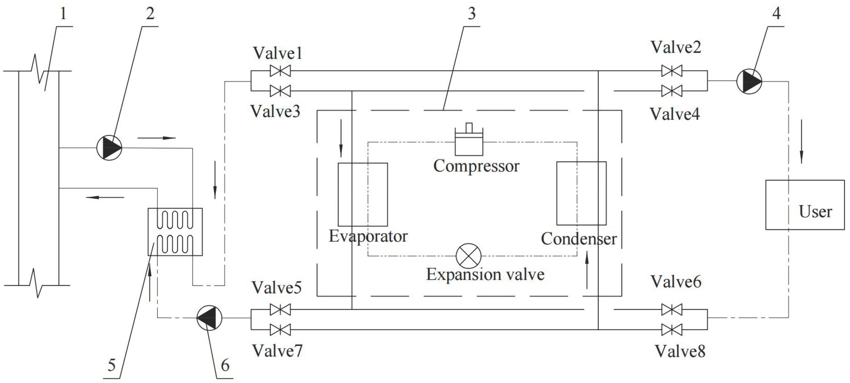
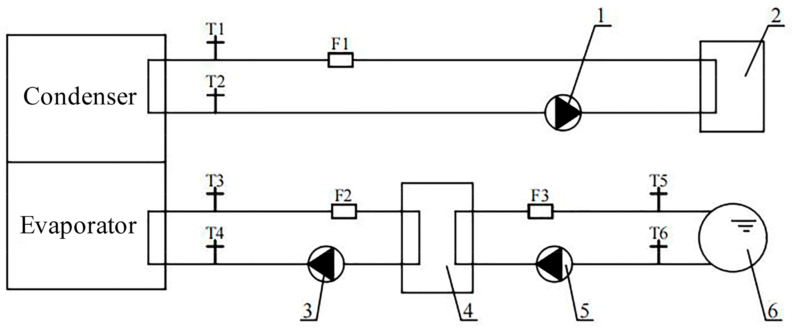
2.1. System Principle

The flow of the sewage source heat pump system is shown in Figure 1. From the Figure, it can be seen that the system consists of four main parts: the sewage drainage system, the sewage—intermediate water heat exchange system, the Freon circulation system, and the terminal air conditioning water circulation system. Among them, the sewage take-off and drainage system refer to the sewage in the dry canal that is lifted by sewage pump 2 so that it is heat exchanged in sewage heat exchanger 5. The heat exchange process transfers the heat of temperature difference within a certain temperature range (approx. 5 °C) in the sewage to the intermediate water. After heat exchange, the effluent is discharged downstream of the trunk sewer to realize the heat exchange cycle of the effluent. The sewage—intermediary water heat exchange system means that after the intermediary water has completed heat exchange with the sewage through the sewage heat exchanger, it is lifted by the intermediary water pump so that it enters the heat pump unit for heat exchange (entering the unit evaporator to release heat in winter and entering the unit condenser to absorb heat in summer), thus forming a closed cycle. The function of the Freon circulation system is that the liquid refrigerant absorbs the heat of circulating water (intermediary water in winter and end circulating water in summer) in the evaporator and turns from a low-temperature and low-pressure liquid refrigerant into a low-temperature and low-pressure gaseous refrigerant, and then enters into the compressor. After being compressed, it becomes a high-temperature and high-pressure gaseous refrigerant, and then passes through the condenser to release the heat to the circulating water (winter end circulating water and summer intermediary water), and then becomes a high-temperature and high-pressure liquid refrigerant. Finally, after being throttled and depressurized by the throttling device, it turns into low-temperature and pressure liquid refrigerant and then enters the evaporator to realize a new cycle. The function of the end air conditioning water circulation system is that the end user water is transported by the system circulation pump 4, absorbing heat from the unit condenser in winter and releasing cold heat to the building users after absorbing cold from the unit evaporator in summer to realize the end cycle. The system is switched between winter and summer functions by opening or closing valves 1–8 on the pipeline.

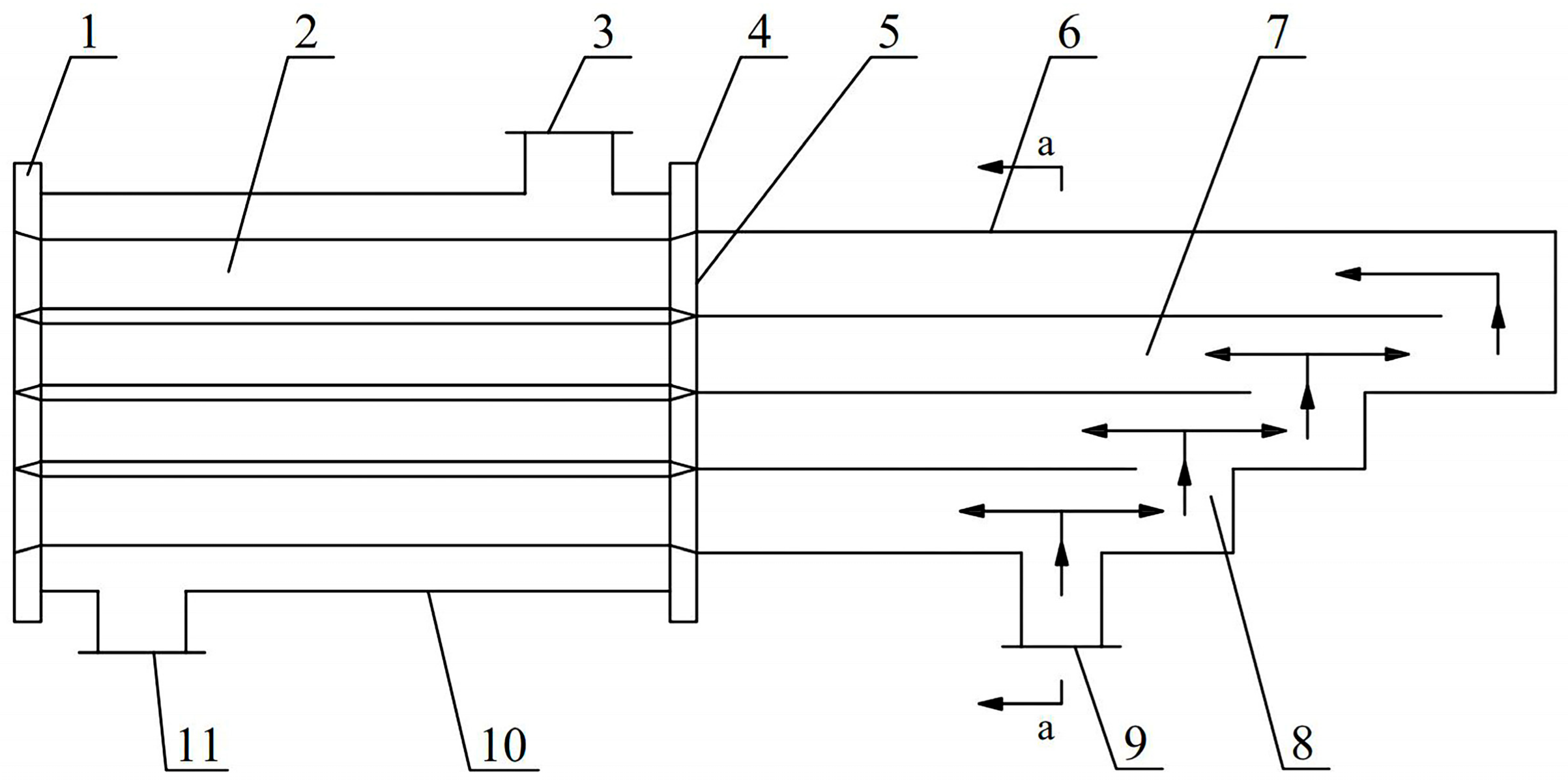
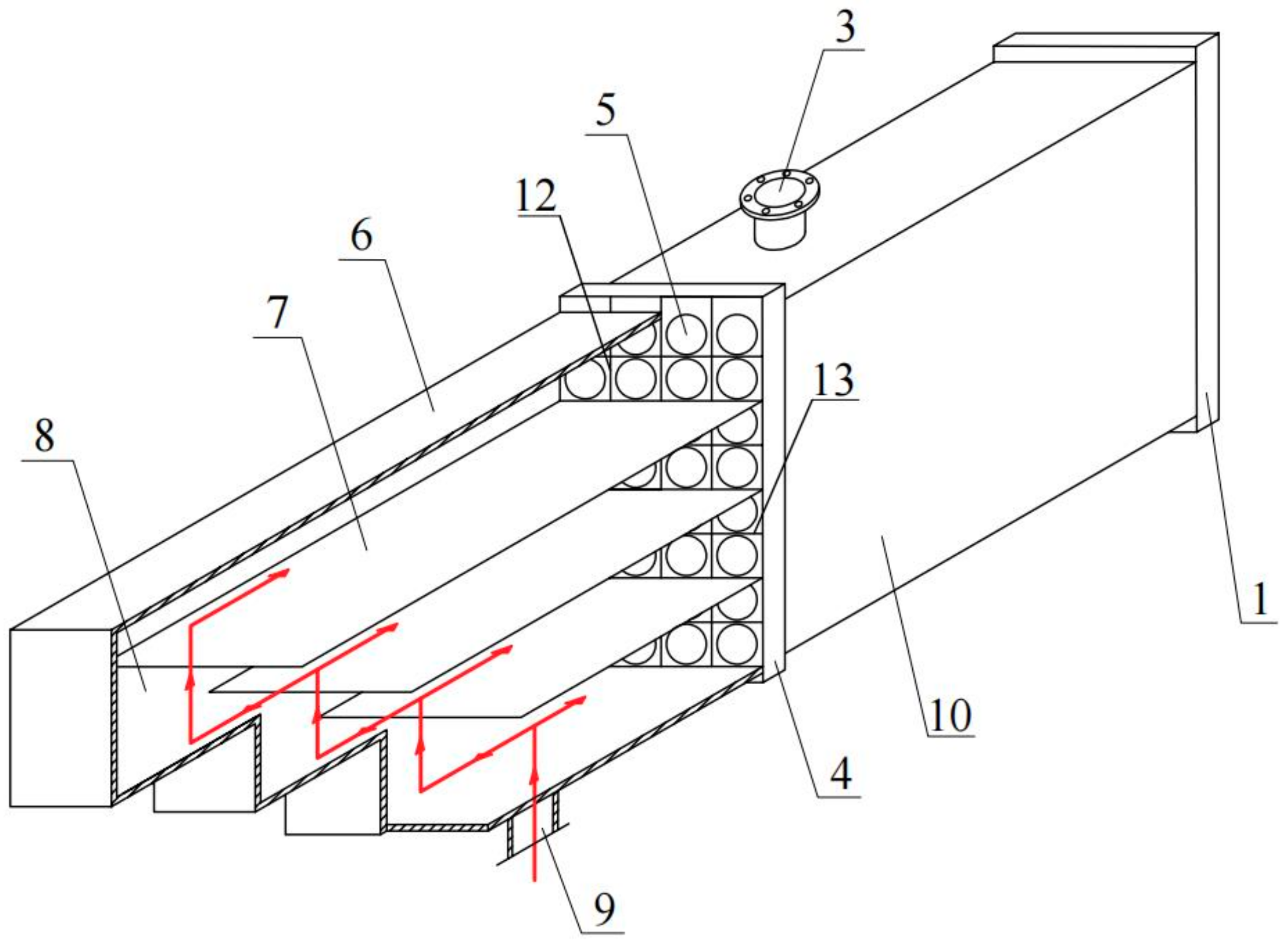
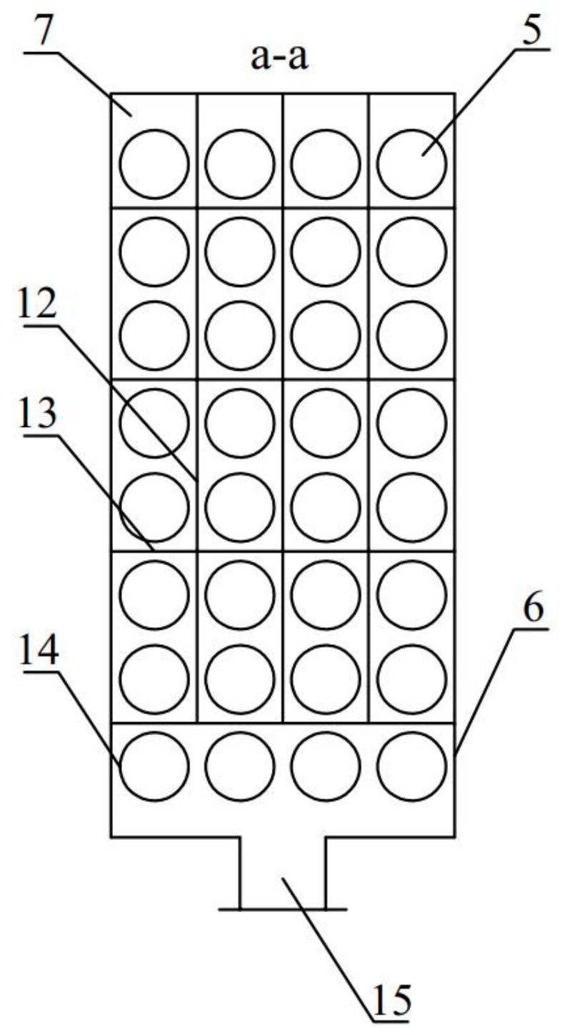
2.2. Special Heat Transfer Technology for Sewage

From the system principle introduced earlier, it is clear that the key core technology of sewage source heat pumps is how to solve the problem of blockage, fouling, and corrosion in the process of sewage heat exchange. The special heat exchanger [18] can effectively solve the above problems. Before entering the heat exchanger, the sewage first passes through the channeling shell on the right side of the heat exchanger, as shown in Figure 2, Figure 3 and Figure 4. The interior of the evacuated shell is set up with multiple parallel separation flow channels. Once the effluent flows in from the effluent inlet, it passes through the first flow separation port, where part of the effluent flows to the left to the inlet, and part of the effluent flows to the right to the next flow separation port. The part of the effluent flowing to the right at the flow separation is divided into two parts; one part flows to the next inlet, and the other part flows to the next flow separation. This continues until the flow reaches the longest separated flow channel. In summary, the diversion housing is used to divide the effluent into two parts by using the flow channel separator so that the flow direction is 180°, which ensures that suspended matter does not form a blockage at the inlet.
The left side of the heat exchanger is equipped with a number of diversion partitions and bending partitions on the left and right tube plates, respectively. The partitions divide the multi-layer heat exchanger tubes into several groups of tube bundles in the direction of water flow, and each group of tube bundles is not connected to each other. The effluent enters the heat exchanger tube one by one through the inlet after passing through the separated flow channel. The effluent will finally flow out from the outlet of the last heat exchanger tube of each group of the tube bundle, i.e., from the outlet, under the barrier of the evacuation partition and the bending partition. The effluent will be discharged through the effluent outlet set in the lower part of the diversion-type housing. Clean water or refrigerant as a medium enters the heat exchanger from the medium inlet and exchanges heat with the sewage in the heat exchanger tube, and the clean water or refrigerant flows out from the medium outlet after the heat exchange is finished.
The setting of the spacer in the left and right tube plates of the heat exchanger can also play a certain role in preventing blockage. Because the sewage heat exchange tube of the heat exchanger is a single tube structure (only one inlet and outlet), the pressure difference before and after the plugging site is the pressure difference between the inlet and outlet. If the suspended matter stays in a heat exchanger tube and is about to form a blockage, the pressure before and after the blockage part will reach tens of kPa. This pressure can completely push the suspended matter and flow out. The pressure difference between the inlet and outlet is the pressure difference between the inlet and outlet. This heat transfer technology can effectively solve the problem of blockage of suspended matter by adopting the method of pipe mouth separation, inner pipe mouth separation, and pipe group isolation. Because of the structural characteristics of the special sewage heat exchanger, it can also solve the existing plate structure heat exchanger method of insufficient pressure-bearing capacity, serious water leakage accidents, and casing structure of steel consumption problems. At the same time, the problem of suspended matter and impurity retention in the flow channel of the plate-type wide flow channel structure can also be effectively solved. At the same time, both sides open the door design, allowing for convenient transition season high-pressure water cleaning, conducive to heat exchanger periodic maintenance [19].
Municipal wastewater contains a large number of microorganisms, such as sulfate-reducing bacteria, metal-reducing bacteria, and iron bacteria. These bacteria and fungi will cause some corrosion to the pipeline. In addition, the sewage contains Ca2+, Cl, H+, Na+, and NO3− plasma, all of which will have chemical reactions with the pipeline and cause corrosion to the pipeline. For pipeline corrosion protection, the cathodic protection method of hot dipping zinc and sacrificial anode can be used according to the water quality. Hot dip galvanizing means that the steel components are de-rusted and then immersed in a high-temperature zinc solution at approx. 600 °C so that a zinc layer is attached to the surface of the steel components, thus serving the purpose of corrosion protection. The cathodic protection method of sacrificial anode means that the more reductive metal is used as the protective electrode, and the protected metal, which is the sewage pipe, is connected to form a primary cell. At this time, the more reducing metal will be consumed as a negative oxidation reaction, while the sewage pipe as the positive electrode can avoid corrosion.

3. Engineering Application Analysis

3.1. Project Overview

The total construction area of an office building in Qingdao is 28,000 m2. Its design heating heat load in winter is 1400 kW, and the design cooling load in summer is 2016 kW. This project uses the primary sewage source heat pump technology to heat the building in winter and air conditioning in summer. The sewage used in this project is from the main sewage channel of the city, and the water quantity is sufficient. Its flow rate is much higher than the sewage flow required by the building’s heating and cooling load. According to the cold and hot demands of the building, the project extracts the sewage required by the design from the trunk canal for heating and cooling the building. Sewage heat exchanger adopts the special heat transfer technology of sewage, which can effectively solve system blockage, corrosion, and other problems. The system equipment selection is shown in Table 1.

3.2. Engineering System Test Methods

Main test parameters: During system operation in winter and summer, the temperature and flow rate of the condenser or evaporator in and out of the unit from the end user side, the temperature and flow rate of sewage inlet and outlet, the temperature and flow rate of the evaporator in and out of the unit with intermediate water, the power consumption of the unit compressor, the power consumption of circulating pump and sewage pump at the end user side [20,21,22]. During the project testing period, two heat pump units were operated simultaneously from December to February. During this period, two groups of special sewage heat exchangers also run at the same time, the corresponding sewage circulation pump, the intermediate water circulation pump, and the end of the circulation pump two at the same time. In March, only one heat pump unit was running. During this period, only one set of special sewage heat exchangers will be operated, along with one corresponding sewage circulation pump, intermediate water circulation pump, and terminal circulation pump. Two heat pump units are operated from June to August in summer. During this period, the operation of two groups of special sewage heat exchangers, the corresponding sewage circulation pump, intermediate water circulation pump, and end circulation pump, at the same time to run two. Only one heat pump unit is running in September. During this period, one special sewage heat exchanger is operated, and the corresponding sewage circulating pump, intermediate water circulating pump, and terminal circulating pump are operated. The arrangement of measuring points is shown in Figure 5, and the main measuring instruments and their accuracy are shown in Table 2.

3.3. Main Performance Parameters of Heat Pump System

The test data is processed by the following Equations [23].
The heat pump unit heating performance factor can be calculated according to Equation (1):
COP u 1 = Q h W u 1
where COPu1 is the heating performance coefficient of the heat pump unit; Qh is the winter heat supply of the sewage source heat pump unit, kW; Wu1 is the power consumption of the unit during the heating season, kW.
The cooling performance factor of the heat pump unit can be calculated according to Equation (2):
COP u 2 = Q c W u 2
where COPu2 is the cooling performance coefficient of the heat pump unit; Qc for sewage source heat pump unit cooling capacity in summer, kW; Wu2 is the electric power consumed by the unit during the cooling season, kW.
The heat pump system heating performance factor can be calculated according to Equation (3):
COP s y s 1 = Q h W s y s 1
where COPsys1 is the heat pump system heating performance factor; Wsys1 is the system power consumption in the heating season, kW.
The system power consumption is:
W sys = W u + W e + W m + W s
where Wu is the power consumption of the heat pump unit, kW; We is the power consumption of the end circulation pump, kW; Wm is the power consumption of the intermediate water circulation pump, kW; Ws is the power consumption of the sewage circulation pump, kW.
The cooling performance factor of the heat pump system can be calculated according to Equation (5):
COP s y s 2 = Q c W s y s 2
where COPsys2 is the cooling performance factor of the heat pump system; Wsys2 is the electrical power consumed by the system during the cooling season, kW.
The heat transfer coefficient of the effluent heat exchanger can be calculated according to Equation (6):
K w = Q m A Δ t m
where Kw is the heat transfer coefficient of the sewage heat exchanger, W/(m2 °C); A is the sewage heat exchanger heat transfer area, m2; Δtm is the average heat transfer temperature difference, °C; Qm is the heat exchanger heat transfer, kW.
Among them, the average heat transfer temperature difference Δtm in the sewage heat exchanger can be calculated according to Equation (7):
Δ t m = Δ t max Δ t min ln Δ t max Δ t min
where Δtmax is the difference between the temperature of the sewage water supply and the temperature of the intermediary water supply, °C; Δtmin is the difference between the temperature of the sewage water return and the temperature of the intermediary water return, °C.
The heat exchanger heat transfer Qm can be calculated according to Equation (8):
Sewage   exhaust   heat :   Q w = c G w Δ t w 3.6
Intermediate   water   absorption   heat :   Q z = c G z Δ t z 3.6
where c is the specific heat capacity of water kJ/(kg·K); Gw is the sewage flow t/h; Δtw is the sewage import and export temperature difference °C; Gz is the intermediary water flow t/h; Δtz is the intermediary water import and export temperature difference °C. Since the heat transfer between the pipeline and heat exchanger shell and ambient air is very small and can be ignored, the heat release of sewage and intermediate water absorption should be basically equal as the basis for checking the test data. When calculating the heat transfer, the average value is taken as follows:
Q m = Q w + Q z 2

3.4. Uncertainty Analysis of Each Measured Quantity of the System

The heat supply and cooling capacity of the system, the heat transfer coefficient of the heat exchanger, and the COP value are indirectly measured or calculated by multiple parameters, so the measurement accuracy of the relevant parameters will certainly directly affect the total measurement accuracy. In order to determine the credibility of the experimental test results in this paper, an error analysis is conducted in this subsection for each of the above three parameters.
The uncertainty of the system heat supply or cooling capacity is derived from the supply flow rate v, supply temperature t1, and return temperature t2, i.e., E (δQ) = f (v, t1, t2). The uncertainty of the heat transfer coefficient of the heat exchanger is derived from the system heat supply or cooling capacity and the logarithmic mean temperature difference Δtm, i.e., E (δK) = f (Q, Δtm). The uncertainty of the COP value is derived from the system heat supply or cooling capacity and the power consumption W, i.e., E (δCOP) = f (Q, W). The calculated results are shown in Table 3.

3.5. Heat Pump System Performance Analysis

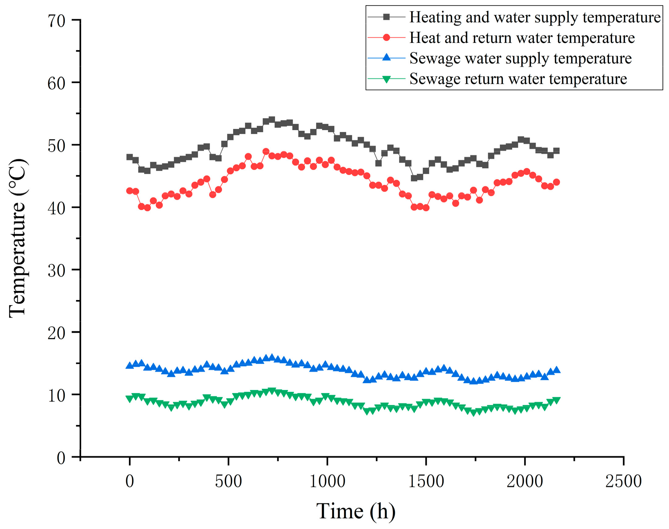
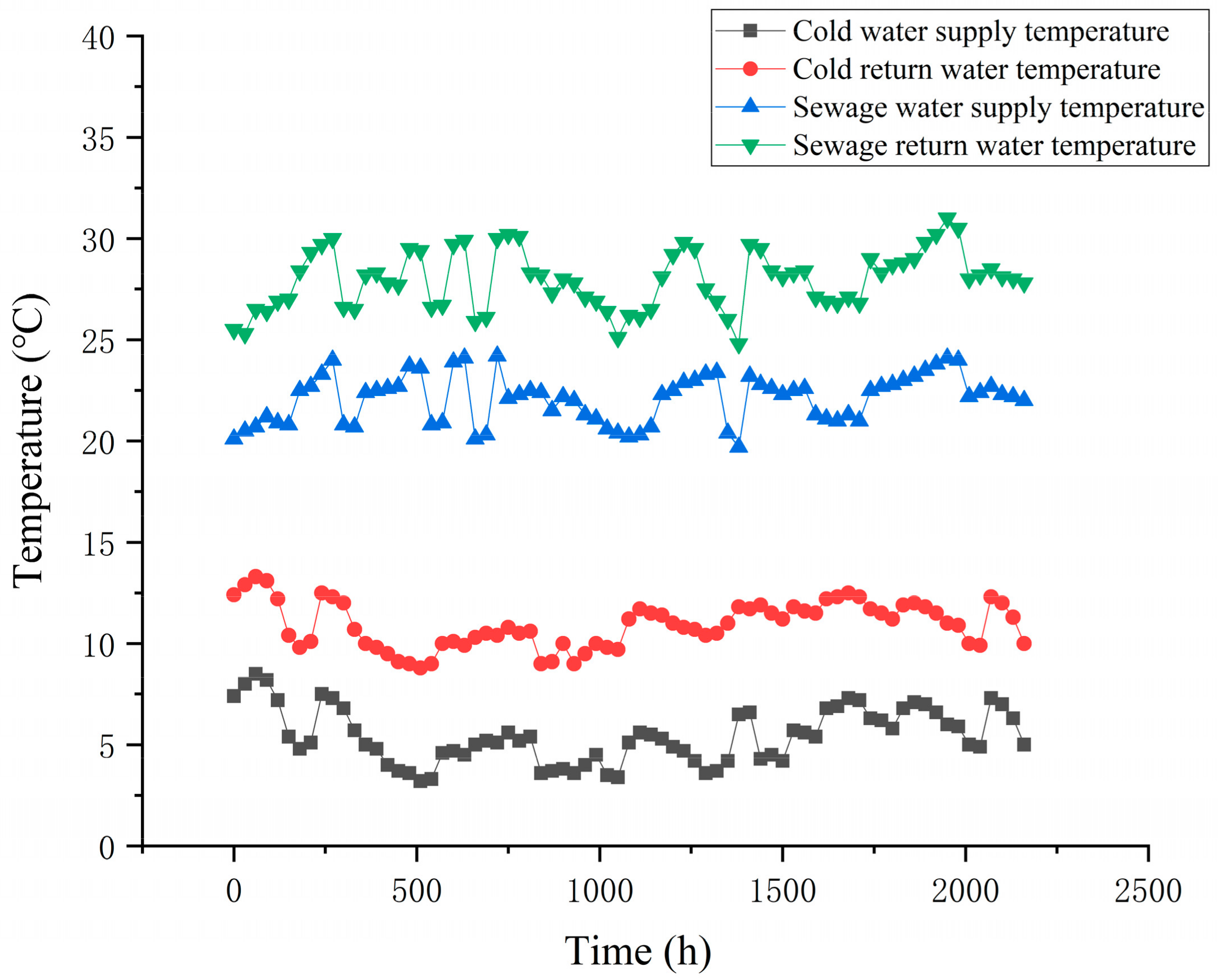
3.5.1. Temperature Variation

After the stable operation of the unit, the heating supply and return water and sewage supply, and return water were monitored in winter, and the results are shown in Figure 6. During the test period, the hot water supply temperature of the heat pump unit was between 44.6 and 54 °C, and its average temperature was 49.28 °C. At this time, the hot water return water temperature of the heat pump unit ranges from 39.9 °C to 48.9 °C, and its average temperature is 44.02 °C. The maximum temperature difference between the hot water supply and the return of the heat pump unit is 6 °C, the minimum is 3.5 °C, and the average temperature difference is 5.26 °C. The temperature of sewage supply in winter ranges from 12 °C to 15.8 °C, and its average temperature is 13.71 °C. At this time, the backwater temperature of sewage is between 7.2 and 10.7 °C, and the average temperature is 8.77 °C. The maximum temperature difference between water supply and return is 5.3 °C, the minimum is 4.6 °C, and the average temperature difference is 4.93 °C. It can be seen that this building uses the primary sewage trunk as the heat source in winter, and the hot water supply temperature can always meet the needs of users.
Summer cooling cold water supply and return temperature and sewage supply and return temperature are shown in Figure 7. During the test period, the cold-water supply temperature of the heat pump unit was between 3.2 and 8.5 °C, and its average temperature was 5.42 °C. At this time, the cold-water return water temperature of the heat pump unit ranges from 8.8 to 13.3 °C, and the average temperature is 10.93 °C. The temperature difference between the cold-water supply and the return of the heat pump unit is between 4.8 and 7.6 °C, and the average temperature difference is 5.51 °C. The water supply temperature of sewage in summer ranges from 19.7 °C to 24.2 °C, with an average temperature of 22.08 °C. At this time, the backwater temperature of sewage is 24.8~31 °C, and the average temperature is 27.96 °C. The temperature difference between the supply and return water of sewage is 3.5~8.1 °C, and the average temperature difference is 5.87 °C. It can be seen that this building takes the primary main sewage channel as the cold source in winter, and the cold-water supply temperature can always meet the needs of users.

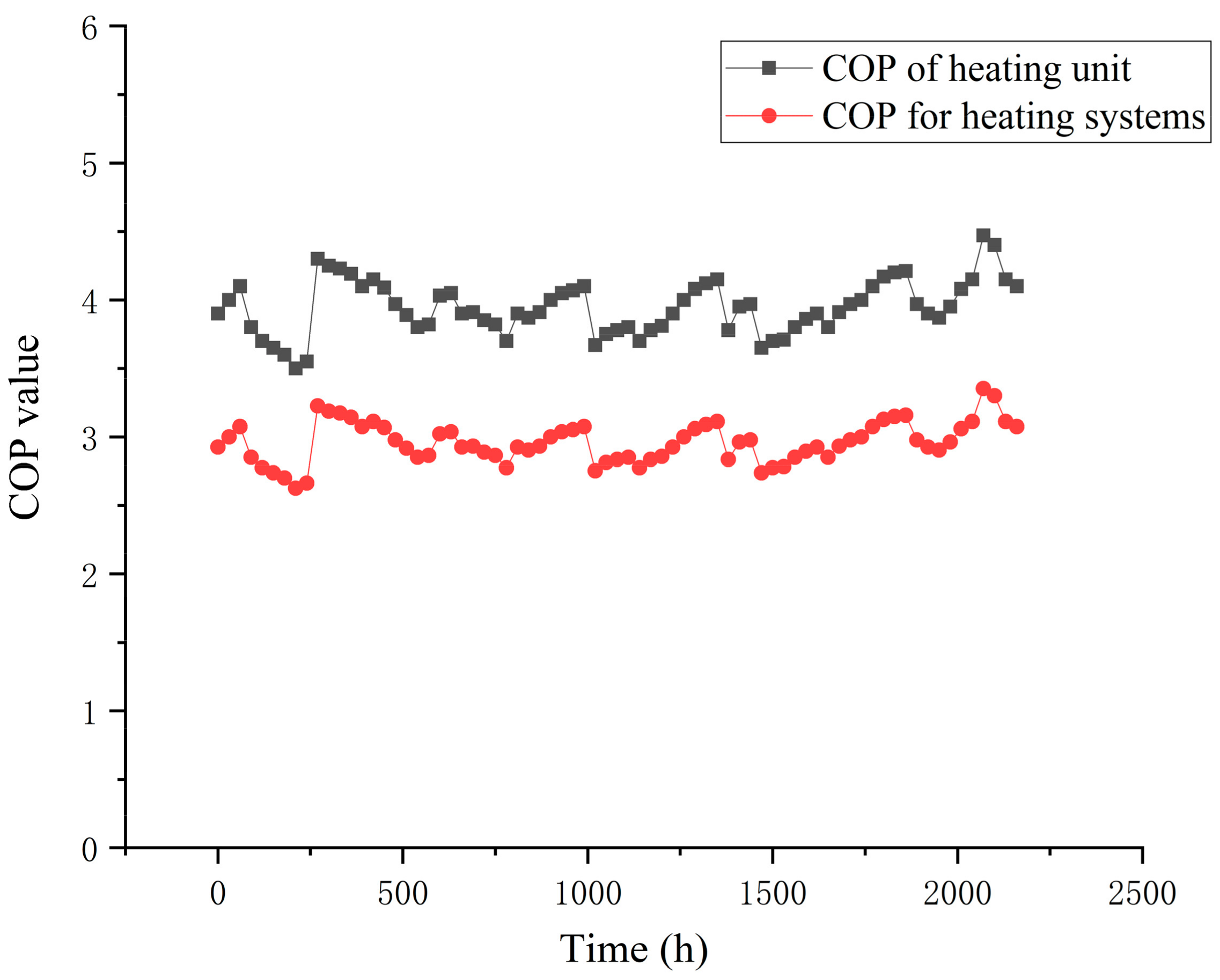
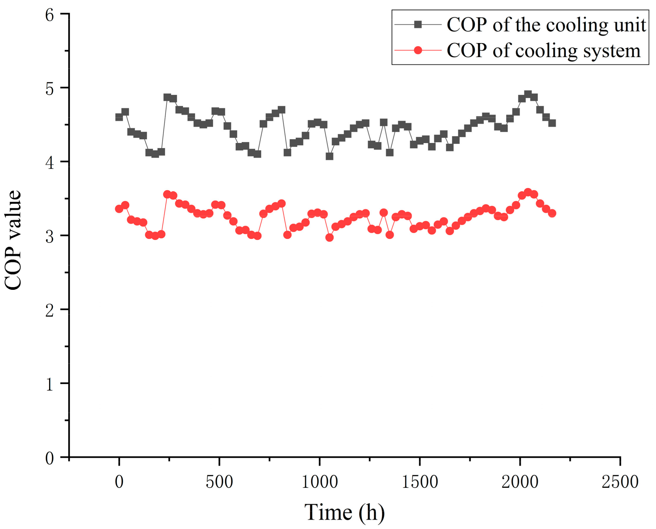
3.5.2. System Key Performance Factor Changes

The test data of this wastewater source heat pump system were compiled and analyzed to obtain the winter and summer coefficients of performance (COP) of its unit and system, as shown in Figure 8 and Figure 9. During the test period, the maximum value of the unit’s winter heating performance coefficient COPu1 was 4.47, the minimum value was 3.5, and the average value was 3.95; the maximum value of the system’s winter heating performance coefficient COPsys1 was 3.35, the minimum value was 2.63, and the average value was 2.96. The maximum value of the unit’s summer cooling performance coefficient COPu2 was 4.91, the minimum value was 4.07, and the average value was 4.45. The maximum value of COPsys2 was 3.58, the minimum value was 2.97, and the average value was 3.25.
The test data of the unit was compiled to obtain its heat transfer coefficient, as shown in Figure 10. The heat transfer coefficient of this wastewater heat exchanger can reach the maximum value of 2003 W/(m2·°C) when the unit first starts operation, i.e., when the wastewater heat exchanger was not yet fouled. However, after the unit has been running smoothly for a period of time, a biofouling layer is formed in the wastewater heat exchanger tube, resulting in a decrease in the heat transfer coefficient of the wastewater heat exchanger, which finally stabilizes at approx. 982 W/(m2·°C). The heat transfer effect of the sewage heat exchanger decreased by approx. half, which shows that the fouling thermal resistance has a great impact on the heat transfer effect of the sewage heat exchanger [24].

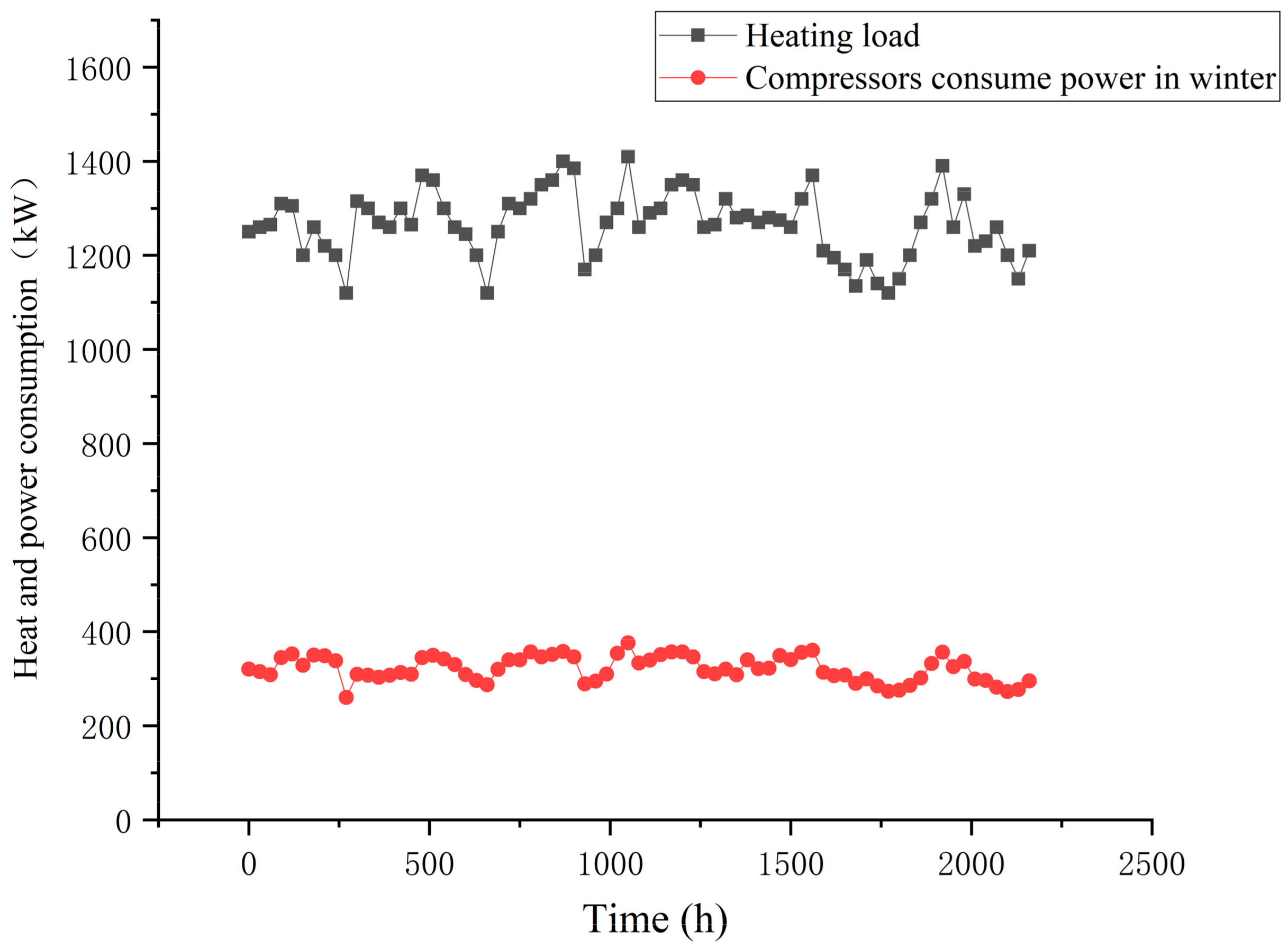
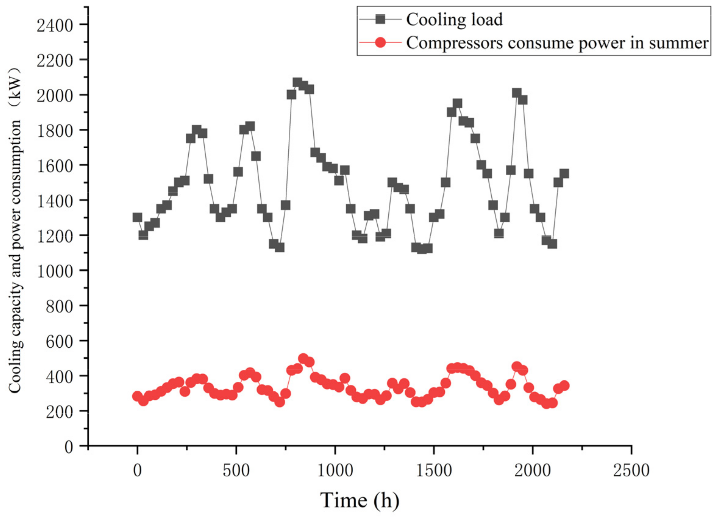
3.5.3. Unit Heating/Cooling Capacity and Power Consumption

Based on the measured data, the heat supply and compressor power consumption in winter is calculated as shown in Figure 11. During the test period, the maximum heat supply of the unit in winter was 1410 kW, the minimum value was 1120 kW, and the average value was 1266.1 kW; the maximum power consumption of the compressor was 376 kW, the minimum value was 260.45 kW, and the average value was 321.91 kW.
The cooling capacity and power consumption of the compressor in summer are shown in Figure 12. During the test period, the maximum cooling capacity of the unit in summer was 2071 kW, the minimum value was 1122 kW, and the average value was 1488.97 kW; the maximum power consumption of the compressor was 497.57 kW, the minimum value was 240.25 kW, and the average value was 335.6 kW.
In summary, the sewage source heat pump unit can operate efficiently, safely, and stably to meet the heat demand of users, and it has a high heating performance coefficient, and can fully recover the waste heat resources in sewage, and provide sufficient heat for heating buildings by consuming less electricity [25].

4. Analysis of System Economy and Energy Saving

4.1. Energy Efficiency Analysis

During the winter heating season, when the available heat of sewage is Qw, the heating capacity can be calculated by Equation (9):
Q h = COP s y s 1 COP s y s 1 1 Q w
where Qw is the available heat of sewage, kW.
The primary energy consumption of the sewage source heat pump system can be calculated by Equation (10):
Q w f = 1 COP s y s 1 1 Q w · 1 E w
where Q w f is the primary energy consumption of the sewage source heat pump system for heating, kW; Ew is the primary energy utilization rate of the driving energy of the sewage source heat pump unit, taken as 0.31.
Primary energy consumption for heating by coal-fired boilers can be calculated by Equation (11):
Q t f = Q h E t = COP s y s 1 E t COP s y s 1 1 Q w
where Q t f is the primary energy consumption of coal-fired boiler heating, kW; Et is the primary energy utilization rate of coal-fired boiler heating, taken as 0.63.
During the summer cooling season, when the available cooling capacity of sewage is Qw, the available cooling capacity can be calculated by Equation (12):
Q c = COP s y s 2 1 + COP s y s 2 Q w
where Qw is the available cooling capacity of wastewater, kW.
The primary energy consumption of the sewage source heat pump system for refrigeration and air conditioning can be calculated according to Equation (13):
Q w f = 1 1 + COP s y s 2 Q w · 1 E w
where Q w f is the primary energy consumption of the sewage source heat pump system refrigeration and air conditioning, kW; Ew is the primary energy utilization rate of the driving energy of the sewage source heat pump unit, taken as 0.31.
The primary energy consumption of the chiller and cooling tower system can be calculated according to Equation (14):
Q t f = Q c E t = COP s y s 2 1 + COP s y s 2 1 E t Q w
where Q t f is the primary energy consumption of the chiller and cooling tower system, kW; Et is the primary energy utilization rate of the chiller and cooling tower system, taken as 0.97 [26].
The primary energy consumption of the air source heat pump system in winter and summer is the same as that of the sewage source heat pump system above. According to the usage data of several air source heat pump manufacturers and related literature, the COP of the air-source heat pump system is 2.8 in winter and 3.0 in summer [27].
According to the calculation results of the mathematical model, as shown in Figure 13, the primary energy consumption of the sewage source heat pump system for heating in winter is 1525.72 kW, that of the air source heat pump system is 1612.90 kW, and that of the coal-fired boiler is 2222.2 kW. Therefore, the energy consumption of the heat pump unit is only 68.66% of that of the coal-fired boiler and 94.5% of that of the air source heat pump system. The primary energy consumption of the cooling sewage source heat pump system in summer is 2000.99 kW, the primary energy consumption of the air source heat pump system is 2167.74 kW, and the primary energy consumption of the chiller and cooling tower system is 2078.35 kW. Therefore, the energy consumption of the heat pump unit is 92.31% of that of the air source heat pump system and 96.27% of that of the water chiller.

4.2. Economic Benefit Analysis

Compared with coal-fired boilers with traditional heating methods, the operation cost of a sewage source heat pump system in the heating season can be calculated by Equation (15) as follows:
C 1 = Q 1 q e η g 1000 p r Q 1 3600 × COP u 1 P × n 1
where C1 is the operation cost saved during the heating season, yuan; Q1 is the daily heat supply in the heating season, which is 4.56 × 10⁶ kJ. qe is the calorific value of standard coal, which is 29,310 kJ/kg. ηg is the efficiency of traditional coal-fired boilers, taking 60%; pr is the standard coal price, taking 1592 yuan /t; P is the power electricity price, 0.79 yuan/kWh; n1 indicates the heating period.
Compared with the traditional refrigeration chiller and cooling tower system, the operation cost saved by the application of a sewage source heat pump system in the cooling season can be calculated by Equation (16) as follows:
C 2 = Δ D × P × n 2
where C2 is the operating cost saved by the use of the sewage source heat pump system during the cooling season, yuan; n2 is the cold supply period, 90 days; ΔD is the daily electricity saving in the cooling season, which can be calculated according to Equation (17) as follows:
Δ D = D f D w = Q 2 3600 1 ε a 1 COP u 2
where Df is the daily power consumption of the cooling water chiller and cooling tower system, kWh; Dw is the daily energy consumption of the sewage source heat pump system, kWh; Q2 is the daily cooling capacity of 5.36 × 10⁶ kJ in the cooling season. εa is the refrigeration performance parameter of the chiller and cooling tower system and is 4.
After calculation, the results are shown in Table 4. It can be seen that the sewage source heat pump system has significant economic benefits.

4.3. Environmental Benefit Analysis

Pollutant emission reduction during the heating season can be calculated by Equation (18) as follows:
Δ m h , i = M 1 × Δ R h , i
where Δmh,i is pollutant emission reduction in heating season, kg, where i represents the four types of pollutants calculated: CO2, NOx, SOx, and dust. ΔRh,i is the mass of various pollutants produced by burning 1 kg coal, kg/kg, and its value is shown in Table 5; M1 refers to the daily coal saving in heating season (kg), which can be calculated according to Equation (19) as follows:
M 1 = Q 1 q e 1 η g 1 η e COP u 1
where ηe is the output efficiency of the sewage source heat pump unit, taking 30%.
Pollutant emission reduction during the cooling season can be calculated by Equation (20) as follows:
Δ m c , i = M 2 × Δ R c , i
where, Δmc,i is pollutant emission reduction in the cooling season, kg; ΔRc,i is the mass of various pollutants produced per 1 kWh power generation, kg/kWh, and its value is shown in Table 4; M2 is the daily coal saving amount in the cooling season (kg), which can be calculated according to Equation (21) as follows:
M 2 = Δ D × 3600 q e × η f
where ηf is the primary energy efficiency, which is 35%.
The calculation results are shown in Table 6. It can be seen from the results that the use of sewage source heat pump systems is very beneficial to the environment, especially for carbon dioxide emissions, and has an obvious carbon reduction effect, which is in line with the current world emission reduction situation.

5. Conclusions

This paper introduces a sewage source heat pump system using special heat transfer technology for sewage and details the working principle of the sewage source heat pump and the key core technology of a special sewage heat exchanger. The system is illustrated by an actual project in Qingdao, China, which uses raw urban sewage as the heat pump source to realize a 28,000 m2 office building for winter heating and summer air conditioning. The key equipment of the system was designed and selected, and the system operation parameters were collected for one year. By compiling and calculating the collected data, the cooling and heating capacity and performance of the whole system were analyzed. Based on the calculation results, the following conclusions were drawn:
(1)
The temperature of municipal sewage was 12~15.8 °C in winter and 19.7~24.2 °C in summer, which was very suitable as a low-level cooling and heating source for heat pump systems;
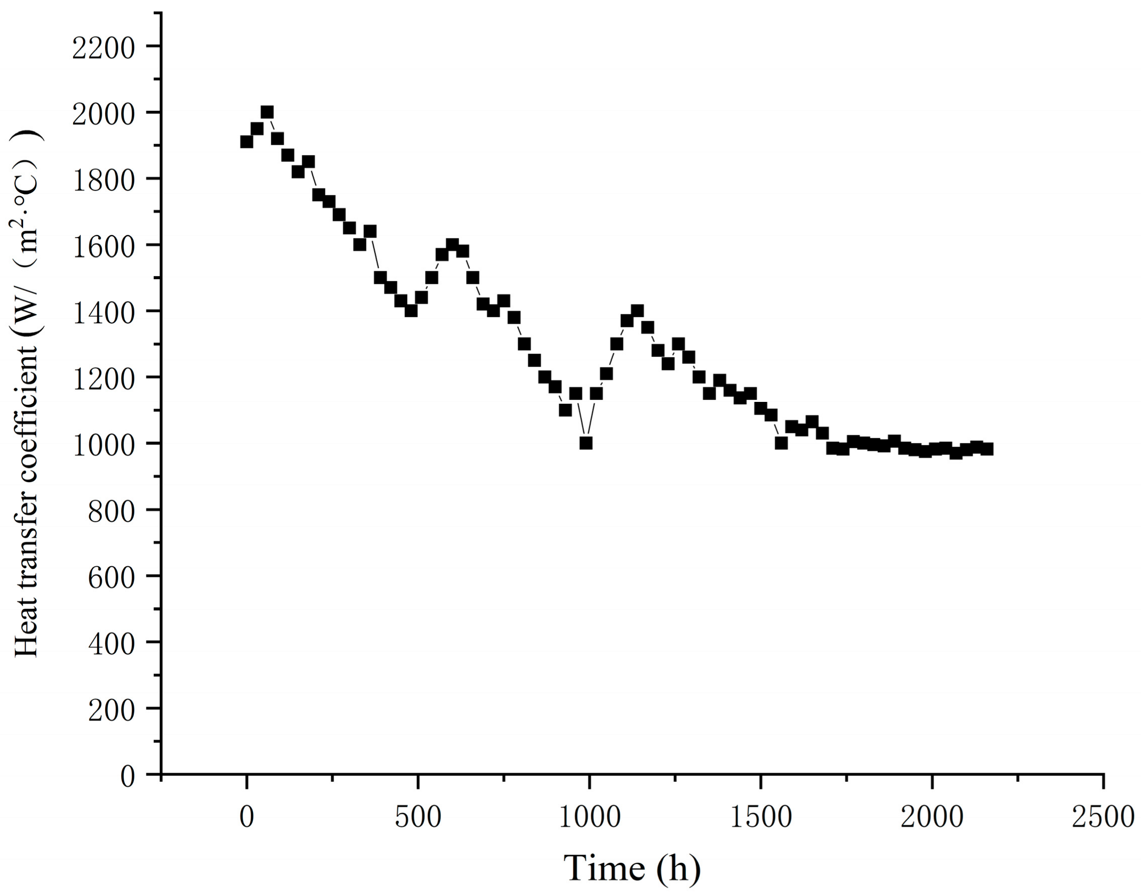
(2)
Fouling has a huge impact on the heat transfer effect of the sewage heat exchanger. When the system initially operated, the heat exchanger was free of fouling generation, and the heat transfer coefficient of this sewage heat exchanger could reach the maximum value of 2003 W/(m2 °C). When the unit ran smoothly for a period of time, the thermal fouling resistance gradually increased, the heat transfer coefficient of the sewage heat exchanger gradually decreased, and its heat transfer coefficient finally stabilized at approx. 982 W/(m2·°C);
(3)
The system operated stably in winter and summer during the test period, with an average heat supply of 1266.1 kW and an average power consumption of 321.91 kW in winter, and an average cooling capacity of 1488.97 kW and an average power consumption of 335.6 kW in summer;
(4)
During the test period, the average COP of the heat pump unit was 3.95 in winter and 4.45 in summer, and the average COP of the heat pump system was 2.96 in winter and 3.25 in summer, taking into account the power consumption of the wastewater pump, intermediary pump, and end circulation pump;
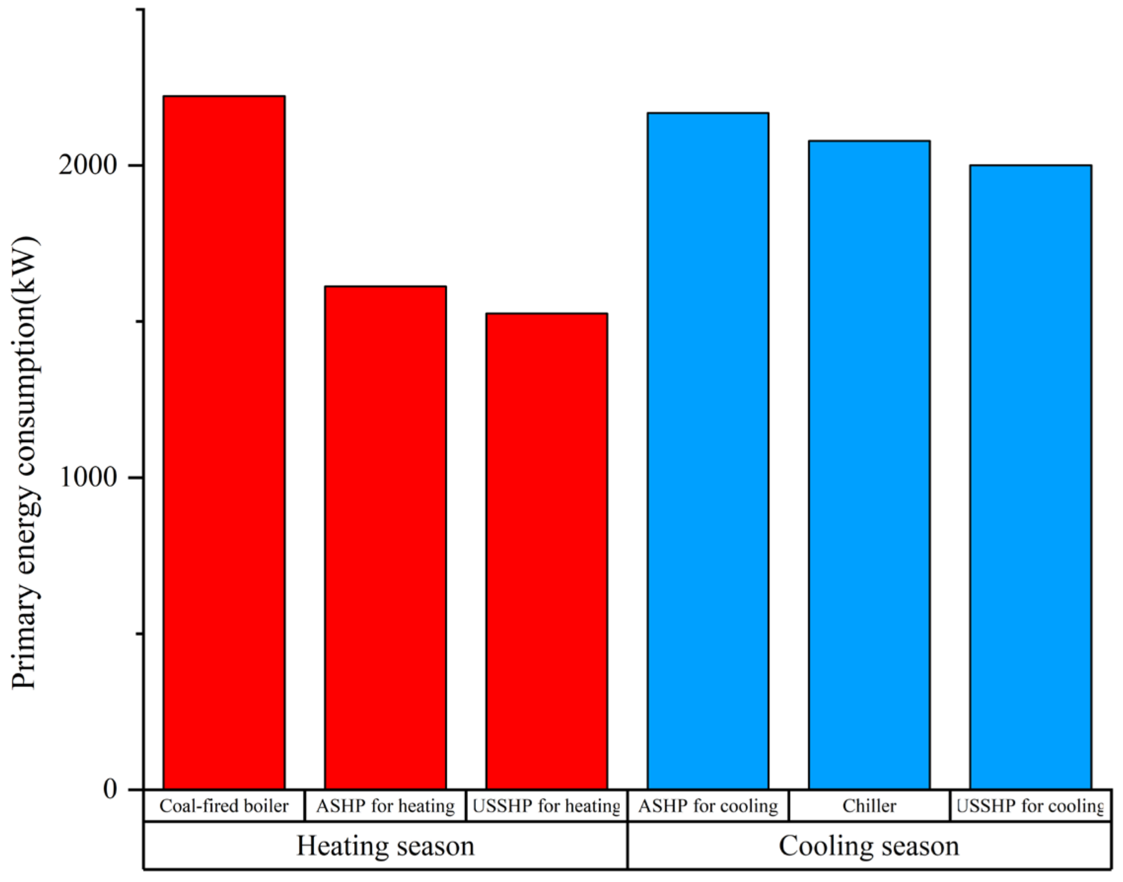
(5)
The energy efficiency analysis shows that the energy consumption of sewage source heat pump systems in winter is 68.66% of that of traditional coal-fired boilers and 94.5% of that of air source heat pump systems. The energy consumption in summer is 96.27% of that of a chiller and cooling tower system and 92.31% of that of an air source heat pump system. The results show that the sewage source heat pump technology has a remarkable energy-saving effect. Through the economic benefit analysis, it is calculated that the operation cost of the heat pump system can be reduced by 17,377.9 yuan per year. Through the analysis of environmental benefits, the use of a sewage source heat pump system can reduce CO2, NOx, SOx, and dust emissions; the CO2 emission reduction effect is the most significant;
(6)
The sewage source heat pump system has enormous economic and social benefits. However, the quality of sewage is poor, the heat exchanger has severe scaling, the flow resistance of sewage heat exchange is high, and the heat transfer coefficient is low. These unfavorable factors limit the application and promotion of the system. Suggest future research on sewage heat exchange technology and the invention of online cleaning and descaling technology to improve the operational performance of the system.

Author Contributions

Z.Z. formal analysis, investigation, methodology, writing—original draft; J.Z. formal analysis, investigation, methodology, writing—original draft; F.M., T.Z. and Y.H., design system and collect data; S.L. Data and picture processing. All authors have read and agreed to the published version of the manuscript.

Funding

In this paper, the research was sponsored by the National Natural Science Foundation of China (Grant No. 51708339), the Natural Science Foundation of Shandong Province (Grant No. ZR2022ME102), the Plan of Introduction and Cultivation for Young Innovative Talents in Colleges and Universities of Shandong Province (2021), and the Scientific and Technological Innovation Project for Youth of Shandong Provincial Colleges and Universities (Grant No. 2019KJH012) and was also supported by the Science and Technology Innovation & Breakthrough Plan of Heze (Grant No. KJCXTP202006) and the Research on the Development of Intelligent Management System and Energy Saving Technology for Public Hospital Building Energy Use (Grant No. GYZ2022HQ44).

Data Availability Statement

Not applicable.

Acknowledgments

The authors of this study wish to acknowledge the contributions of all partners.

Conflicts of Interest

The authors declare no conflict of interest.

References

  1. Cecconet, D.; Raček, J.; Callegari, A.; Hlavínek, P. Energy recovery from wastewater: A study on heating and cooling of a multipurpose building with sewage-reclaimed heat energy. Sustainability 2019, 12, 116. [Google Scholar] [CrossRef]
  2. Pochwała, S.; Paulina, K. Possibility of Obtaining Wastewater Heat from a Sewage Treatment Plant by the Means of a Heat Pump—A Case Study. In E3S Web of Conferences; EDP Sciences: Les Ulis, France, 2018; Volume 44. [Google Scholar]
  3. IEAHPC. Heat Sources[Z/OL]. Available online: http://www.heatpumpcentre.org/Aout~heat~pumps/heat~sources.asp (accessed on 17 May 2012).
  4. Yin, J.; Wei, X. Analysis on the running condition of urban sewage Thermal energy utilization system in Japan. J. Jilin Inst. Civ. Eng. Archit. 1999, 12, 31–38. [Google Scholar]
  5. Quan, Z.; Yin, J. Development Status of Heat Energy Recovery and Utilization of Municipal sewage in Japan. J. Jilin Inst. Civ. Eng. 2003, 3, 4–6. [Google Scholar]
  6. Lindström, H.O. Experiences with a 3.3 MW heat pump using sewage water a8 heat source. Heat Recovery Syst. 1985, 5, 33–38. [Google Scholar] [CrossRef]
  7. Pedersen, S.E.; Stene, J. 18 MW heat pump system in Norway utilizes untreated sewage as heat source. IEA Heat Pump Cent. Newsl. 2006, 24, 37–38. [Google Scholar]
  8. Zhou, W.Z.; Li, J.X.; Tu, G.B. Analysis of wastewater source heat pump system and the prospect of wastewater cold and heat energy utilization. HVAC 2004, 34, 25–29. [Google Scholar] [CrossRef]
  9. Wu, R.H.; Sun, D.X.; Zhang, C.H.; Ma, G.X. Application and research status of urban sewage source heat pump. J. Harbin Inst. Technol. 2006, 38, 1326–1329. [Google Scholar] [CrossRef]
  10. Liu, Z.; Ma, L.; Zhang, J. Application of a heat pump system using untreated urban sewage as a heat source. Appl. Therm. Eng. Des. Process. Equip. Econ. 2014, 62, 747–757. [Google Scholar] [CrossRef]
  11. Wu, R.H.; Chi, F.; Wang, G.; Yu, Y.; Guan, S.; Miao, Z. Evacuated Single Wide Flow Channel Type Heat Exchanger for Sewage or 488 Surface Water. China Patent ZL 201220610653.8, 5 November 2014. [Google Scholar]
  12. Baek, N.C.; Shin, U.C.; Yoon, J.H. A study on the design and analysis of a heat pump heating system using wastewater as a heat source. Sol. Energy 2005, 78, 427–440. [Google Scholar] [CrossRef]
  13. Korea Institute of Energy Research. Feasibility Study on Heat Pump System Using Waste Thermal Hot Water as a Heat Source; Internal Report of Korea Institute of Energy Research: Daejeon, Republic of Korea, 2001. [Google Scholar]
  14. Łokietek, T.; Tuchowski, W.; Leciej-Pirczewska, D.; Głowacka, A. Heat Recovery from a Wastewater Treatment Process—Case Study. Energies 2023, 16, 44. [Google Scholar] [CrossRef]
  15. Qunli, Z.; Zhiming, W.; Chaohui, Y.; Qian, N.; Liwen, J. Field Test Analysis of a Urban Sewage Source Heat Pump System Performance. Energy Procedia 2017, 143, 131–136. [Google Scholar]
  16. Shen, C.; Jiang, Y.; Yao, Y. Experimental study on dry sewage source Heat pump System with self-cleaning. Acta Energ. Sol. Sin. 2013, 34, 154–159. [Google Scholar]
  17. Yao, Z. Application of MIDAD/Gen in space steel structure design. Build. Struct. 2017, 47, 741–743. [Google Scholar]
  18. Wu, R.H.; Chi, F.; Yu, Y.; Miao, Z. A Tubular Evacuation Type Heat Exchange Method for Wastewater or Surface Water. China Patent CN103033073B, 5 November 2014. [Google Scholar]
  19. Song, T.; Tian, J.; Ni, L.; Shen, C.; Yao, Y. Experimental study on performance of a de-foulant hydrocyclone with different reflux devices for sewage source heat pump. Appl. Therm. Eng. Des. Process. Equip. Econ. 2019, 149, 354–365. [Google Scholar] [CrossRef]
  20. Yoo, Y.-J. Fault Detection Method Using Multi-mode Principal Component Analysis Based on Gaussian Mixture Model for Sewage Source Heat Pump System. Int. J. Control. Autom. Syst. 2019, 17, 2125–2134. [Google Scholar] [CrossRef]
  21. Mi, P.; Ma, L.; Zhang, J. Integrated optimization study of hot water supply system with multi-heat-source for the public bath based on PVT heat pump and water source heat pump. Appl. Therm. Eng. Des. Process. Equip. Econ. 2020, 176, 115146. [Google Scholar] [CrossRef]
  22. Wang, Q.; Zhang, X.; Geng, X.; Chen, X.; Xing, M. Experiments on the characteristics of a sewage water source heat pump system for heat recovery from bath waste. Appl. Therm. Eng. 2022, 204, 117956. [Google Scholar] [CrossRef]
  23. Zhang, Q.; Yang, Y.; Wang, B.; Zhang, S. Development and example of high-efficiency urban wastewater source heat pump utilization system. HVAC 2021, 51, 302–306. [Google Scholar]
  24. Mao, N.; Hao, J.; He, T.; Xu, Y.; Song, M.; Tang, J. Unsteady heat transfer properties of spray falling over a horizontal tube in an oily sewage source heat pump. Appl. Therm. Eng. Des. Process. Equip. Econ. 2020, 179, 115675. [Google Scholar] [CrossRef]
  25. Qin, N.; Tian, H. Operational analysis of a newly untreated sewage source heat pump with a plate heat exchanger. Heat Mass Transf. 2022, 58, 683–693. [Google Scholar] [CrossRef]
  26. Wu, R.H.; Zhang, C.H.; Sun, D.X.; Ren, N.Q. Energy saving and environmental evaluation of surface water source heat pump systems in rivers, lakes and seas. J. Harbin Inst. Technol. 2008, 40, 226–229. [Google Scholar] [CrossRef]
  27. Tangwe, S.; Kusakana, K. Using statistical tests to compare the coefficient of performance of air source heat pump water heaters. J. Energy South. Afr. 2022, 33, 40–51. [Google Scholar] [CrossRef]
Figure 1. Flow chart of wastewater source heat pump system. 1—sewage drainpipes; 2—sewage circulation pump; 3—heat pump unit; 4—system circulation pump; 5—sewage heat exchanger; 6—medium water circulation pump. (In winter, valves 2, 3, 5, 8 open, valves 1, 4, 6, 7 close; in summer, valves 1, 4, 6, 7 open, valves 2, 3, 5, 8 close).
Buildings 13 01342 g001
Figure 2. Structure drawing of special heat exchanger for sewage. 1—left tube plate; 2—multi-layer heat exchanger tube; 3—media outlet; 4—right tube plate; 5—inlet; 6—diversion type shell; 7—separation flow channel; 8—flow channel separation port; 9—sewage inlet; 10—shell; 11—media inlet.
Buildings 13 01342 g002
Figure 3. Isoaxial map of special heat exchanger for sewage. 1—left tube plate; 3—media outlet; 4—right tube plate; 5—inlet; 6-diversion type shell; 7—separation flow channel; 8—flow channel separation port; 9—sewage inlet; 10—shell; 12—diversion bulkhead; 13—folding bulkhead.
Buildings 13 01342 g003
Figure 4. Cross-sectional diagram of the special sewage heat exchanger a-a. 5—inlet; 6—diversion type shell; 7—separation flow channel; 12—diversion bulkhead; 13—folding bulkhead; 14—outlet; 15—wastewater outlet.
Buildings 13 01342 g004
Figure 5. Measurement points layout. 1—Scheme; 2—heat users; 3—mediator water circulation pump; 4—heat exchanger; 5—sewage circulation pump; 6—sewage dry canal; T1–T6—temperature measurement points; F1–F3—flow measurement points.
Buildings 13 01342 g005
Figure 6. Winter heating unit supply and return water and sewage supply and return water temperature.
Buildings 13 01342 g006
Figure 7. Summer cooling supply and return water temperature and sewage supply and return water temperature.
Buildings 13 01342 g007
Figure 8. Winter heating unit and system COP.
Buildings 13 01342 g008
Figure 9. Summer cooling unit and system COP.
Buildings 13 01342 g009
Figure 10. Heat transfer coefficient of heat pump heat exchanger.
Buildings 13 01342 g010
Figure 11. Winter heat supply and power consumption of the compressor.
Buildings 13 01342 g011
Figure 12. Summer cooling capacity and compressor power consumption.
Buildings 13 01342 g012
Figure 13. Comparison of primary energy consumption of each air conditioning mode.
Buildings 13 01342 g013
Table 1. Heat pump system equipment selection.
Equipment NameQuantityRemarks
Sewage circulation pump3The flow rate is 170 m3/h, and the head is 28 m
Intermediate water circulation pump3The flow rate is 170 m3/h, and the head is 22 m
End circulation pump3The flow rate is 180 m3/h, and the head is 35 m
Special sewage heat exchanger2Heat exchange area of 350 m2, heat exchange of 1200 kW
Heat pump unit2Single unit heat production of 720 kW with an input power of 165 kW
Cooling capacity of 1050 kW, input power of 240 kW
Table 2. Test instruments and accuracy.
Instrument NameMeasurement Accuracy
Digital temperature meter
(remote transmission type) ACT-201
0.2 level (±0.2%)
WSF-50 intelligent electromagnetic flowmeter±0.5%
8962A1 Multichannel Power Analyzer0.1 level (±0.1%)
Multi-variable low-temperature level and pressure smart meters0.2% FS
The data of this experiment is automatically stored and recorded by the instruments.
Table 3. Uncertainty of various measured quantities of the system.
Parameters AnalyzedMeasurement Uncertainty
E (δQ)7.21%
E (δK)7.84%
E (δCOP)7.26%
Table 4. Operation cost saving of sewage source heat pump system.
Heating SeasonCooling SeasonTotal
Saving amount (yuan)14,3552698.2517,377.9
Table 5. Various categories of pollutants produce mass.
ΔRc,iCO2NOxSOxDust
Quality of pollutants produced during the heating season
(kg/kg)
2.750.0040.030.02
Quality of pollutants produced in the cooling season
(kg/kWh)
1.1260.00160.01230.082
Table 6. Reduction of various pollutants.
Pollutant Reduction (kg)CO2NOxSOxDust
Heating season352.110.513.842.56
Cooling season15.000.020.161.09
Disclaimer/Publisher’s Note: The statements, opinions and data contained in all publications are solely those of the individual author(s) and contributor(s) and not of MDPI and/or the editor(s). MDPI and/or the editor(s) disclaim responsibility for any injury to people or property resulting from any ideas, methods, instructions or products referred to in the content.

