Article

A Finite Element Method Integrated with Terzaghi’s Principle to Estimate Settlement of a Building Due to Tunnel Construction

by
César A. Rodríguez
1,*,
Ángel M. Rodríguez-Pérez
1,*,
Raúl López
2,3,
José Antonio Hernández-Torres
1 and
Julio J. Caparrós-Mancera
1
1
Higher Technical School of Engineering, Campus “El Carmen”, University of Huelva, 21007 Huelva, Andalusia, Spain
2
Department of Forest and Agricultural Sciences and Engineering, University of Lleida, 25003 Lleida, Catalonia, Spain
3
Fluvial Dynamics Research Group (RIUS), University of Lleida, 25003 Lleida, Catalonia, Spain
*
Authors to whom correspondence should be addressed.
Buildings 2023, 13(5), 1343; https://doi.org/10.3390/buildings13051343
Submission received: 25 April 2023 / Revised: 15 May 2023 / Accepted: 18 May 2023 / Published: 20 May 2023

Abstract

:
This study presents the application of the finite element method integrated with Terzaghi’s principle. The definition of a model in oedometric or confinement conditions for settlement estimation of a building after the construction of a tunnel, including the effect of Terzaghi’s principle, is an unresolved problem. The objectives of this work include the demonstration of the need for a minimum of three methodological states to estimate said settlement. For this, a specific methodology is applied to a case study, with eight load steps and four types of coarse-grained soils. In the studied case, two layers of 50 m and 5 m with different degrees of saturation are overlaying an assumed impermeable rock layer. The excavation of a tunnel of 15 m in diameter at a depth of 30 m with drainage lining inside the tunnel is assumed. The minimum distance from the tunnel’s outline to the mat foundation is 15.8 m. It is determined that the settlement, according to Terzaghi’s principle, is around 11% of the total settlement for the most compacted soil types, reaching 35% for the loose soil type, from the tunnel’s outline. In the mat foundation, it implies an increase in the differential settlement of up to 12%. It shows a nonlinear relationship between some of the variables in the analysis. To detect the collapse due to uplifting the tunnel invert, it was determined that it was not appropriate to model in oedometric conditions. The novelty of the investigation relies on identifying and determining the need for a minimum of three states for methodological purposes for a proper quantification of the total settlement: (i) before the construction of the tunnel, (ii) immediately after the excavation of the tunnel, but without groundwater inflow into the tunnel, and (iii) after the tunnelling, with stabilised groundwater inflow into the tunnel.

1. Introduction

The estimation of the settlement due to Terzaghi’s principle after the construction of a tunnel requires analysing the state-of-the-art in different disciplines. In the first place, the problem is located in a building with a possible settlement after the construction of the tunnel. The structural condition of a building’s construction primarily relies on the reception and distribution of loads generated through a competent foundation onto the ground [1]. Once built, repairing defects in a building’s foundation becomes a complex task [2]. The construction of a tunnel in the vicinity of well-founded buildings can induce failure due to unforeseen alterations in the terrain that were not considered in the initial design of the foundation [3]. Failure due to this reason can be caused by the settlement of buildings due to tunnelling [4,5,6]. The affected surface due to the underground excavation progressively evolves depending on the loads and the type of soil. This phenomenon is commonly called surface subsidence [7]. Some frequent causes are due to the vibrations and the subsequent loss of the bearing capacity of the affected soils during excavation [8,9]. Vibrations due to vehicular traffic or by railways can appear [10,11,12], and this can also propagate through tunnels in the operation stage [13].
The interaction of a structure with a porous medium is the cause and object of the appearance of soil mechanics. There is a cause of settlement which is directly related to the porous media that constitutes the soil: pore-water pressure (also referred to as neutral stress) variations [14]. This phenomenon is governed by Terzaghi’s principle, with a long and complex evolution in the state-of-the-art [15]. It states that when stress is applied to a porous material, it is opposed by the pressure of the fluid that fills the pores of the material. This concept was introduced by Karl von Terzaghi in his work Erdbaumechanik [16]. Settlement due to Terzaghi’s principle appears as an opposition to the settlement in a building produced by the elastic or elastoplastic behaviour of the soil. Thus, it appears when there is a variation in the effective stress and not due to the total amount of the effective stress. Nevertheless, the total stress in a granular soil is relevant to determine settlement in a shallow foundation. In this case, the amount of load transmitted by the foundation to the soil is critical [7,17].
Tunnel construction has notoriously evolved, in both construction aspects and modelling of induced settlements. The quantification of the settlement of buildings caused by tunnelling can be obtained by applying different formulations depending on some variables in which the measurability can vary [18]. Analytical models become too complicated when trying to accurately predict the soil behaviour [19,20]. There are also empirical formulations with statistical adjustment in reference to tunnelling. In these cases, the original principle of elastic or elastoplastic deformation of the soil is modified to favour the obtention of more accurate predictions [21]. Although useful, these formulations require adaptations to be used in a general manner. Regarding numeric formulations focused on discretising the problem, they present some drawbacks. Specifically, the coupled relationship of soil and flow in porous media is relevant [22,23,24]. In this context, there are relevant works applying the finite element method (hereafter FEM) [25]. These studies focus on both non-oedometric conditions (also called confinement conditions) [26] and plane strain with severe discontinuities [27]. One of the most recent approaches to estimate settlements is to integrate all these methodologies in a hybrid formulation. This new formulation is on the safe or conservative side regarding the project’s decision-making context [28].
The type of foundation influences the settlement due to the construction of a tunnel. Regarding the type of foundation susceptible to settlements, most of the problems deal with shallow foundation calculations. In the specific case of granular soils, there is extensive experience in this regard [17,29,30]. In the settlement calculations’ context, when referring to primary consolidation, the variation in effective stress is considered, but the time also appears as a key variable in the formulation [31]. Granular materials, whether they are sand or gravel, settle almost instantaneously or over a short period. Therefore, the consolidation concept (although not always, especially in loose soils) is usually associated with cohesive materials such as silts and clays, or with sands or gravels mixed to some degree with cohesive materials [32,33,34]. In the case of deep foundation piles, they are also affected by tunnelling in their vicinity [35]. It is necessary to ensure that the soil-pile-rock complex remains intact without alteration [36,37]. Concerning shallow foundations based on a slab foundation without piles (hereinafter referred to as mat foundations), under analysis in this study, interference with the water table is possible in the case of buildings with a basement or underground car park, as their foundation contact surface is located just a few meters below the ground level [2,38,39]. For this reason, waterproofing measures are necessary, both on the surface and/or in the concrete composition [40]. However, beyond functional and concrete preservation reasons, waterproofing on the contact surface with the mat foundation is ineffective against settlement caused by variations in effective stress. On the other hand, waterproofing of the tunnel can have a reducing effect on settlements, although it is structurally difficult [41].
The integration of the hydrogeological and geotechnical analysis gives rise to an aspect of geological engineering applied to tunnels. When a tunnel is constructed, the hydraulic gradient line (piezometric head) is altered due to the inflow of groundwater into the tunnel [42]. Therefore, it implies pore-water pressure variation, and thus, effective stress variation. The estimation of groundwater inflow into a tunnel represents one of the unknown variables in some problems [43]. Hence, it must be solved due to different reasons: provision of water equipment, water loss in aquifers, structural damages, etc. [44]. Nevertheless, once the groundwater flow is stabilised, in the case where the aquifer disposes of sufficient water inputs, the piezometric head becomes stabilised [45]. Once the piezometric or hydraulic head remains stable for any possible reason (grouting, specific drainage, etc.), and in case there are no alterations in the loads transmitted to the ground, the effective stress also becomes stable since there are no variations in the pore-water pressure [46]. Therefore, the process of primary consolidation, due to the variation of effective stress, finishes in a mat foundation with settlement due to tunnelling (i.e., there is no further settlement for this reason).
In this study, the fundamentals and modelling using the FEM are presented for a proper estimation of the settlement in a semi-deep foundation caused by the excavation of a tunnel in a porous granular medium. The use of the FEM allows obtaining a satisfactory solution by transforming a continuous problem of difficult resolution into a discrete one, requiring for this purpose the use of established approaches in this field of knowledge [47,48,49,50]. An approach based on a displacement formulation has been followed [51]. This study implements the coding and resolution using MATLAB software [52]. The finite element mesh generator Gmsh tool (hereafter Gmsh) is selected [53] to create the discretisation mesh, since it allows an exhaustive control of the process of creating it. The case study involves the variables referring to four different types of granular soils described by Terzaghi [54]. The objectives of this work are: (i) To demonstrate the need for a methodology and to define it in order to obtain the variation of the effective stress without distortion in modelling due to the mechanical effect generated by the tunnel construction. (ii) To obtain the settlement due to Terzaghi’s principle as well as the total settlement for a case study under non-oedometric conditions and demonstrate the desirability of using these unconfined conditions to assess tunnel uplift. (iii) To demonstrate the nonlinearity of partial and total settlement in a constitutive model of elastic granular soil when non-oedometric conditions are used. Additionally, stress and displacement field analysis in non-oedometric conditions are part of the scope of this work. It should be noted that any aspect related to clayey, silty soils, cohesive mixtures, and their deferred settlement is out of the scope of this research.

2. Materials and Methods
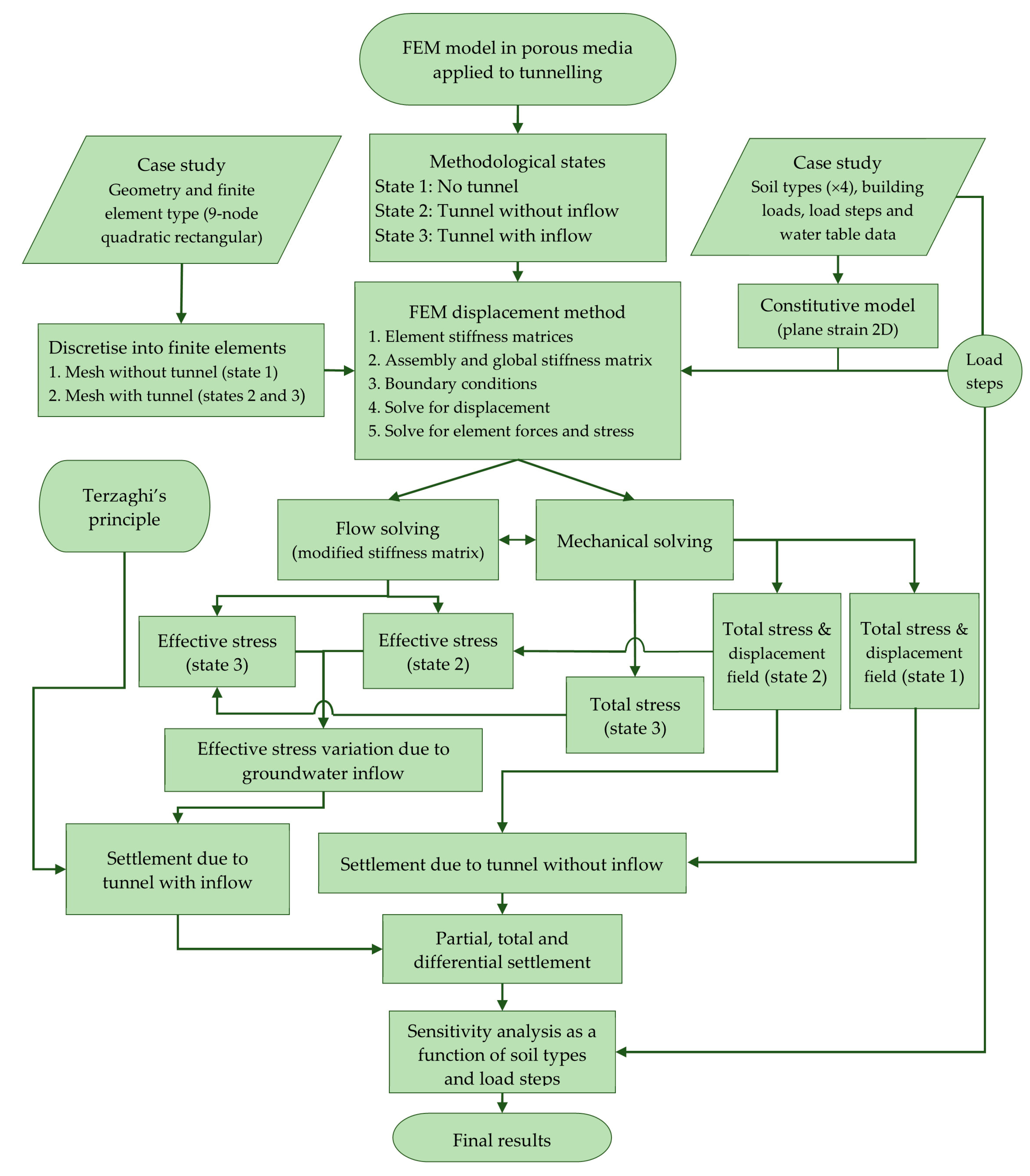
2.1. Methodology

The problem to solve was formulated by starting from the application of the FEM to a porous media [22,23,24,25,48]. It was intended to know the effect of Terzaghi’s principle when estimating the settlement of a building due to tunnelling in granular soils. The process followed requires the study phases of an elastic problem with modelling in porous media (Figure 1). The weak form of the FEM was used, adding Galerkin’s approximation [55]. Including the Terzaghi’s principle in the FEM requires to know the effective stress and its variation due to the groundwater inflow into a tunnel. The problem of flow was solved in three phases, each of them in steady flow conditions. It should be noted that quantifying the settlement’s generation time is not under the scope of this work. Nevertheless, in a porous media composed by the soils of the study case (see Section 2.4), settlement appeared over a short period [31,56].
The implementation of the methodology was carried out using Gmsh and MATLAB tools [52,53,57]. A rational discretisation of the domain was needed. For this purpose, the mesh generation was carried out using Gmsh. The procedure requires two meshes for the three different situations (Figure 2). Three states of the methodology (1, 2, and 3) were needed during the calculation process. In this regard, state 1 represents the situation before the tunnelling, state 2 corresponds to the subsequent situation of the tunnelling without groundwater inflow, and finally, state 3 is the final situation of the tunnel, with a stabilised flow towards the interior of the tunnel (Figure 3). A demonstration of this is fully developed in Section 3.1. A total of 11,352 nodes were evaluated in this study. The mesh of the analysis is of a semi-structured type, with a focus on high-quality finite elements that incorporate quadratic shape functions. To obtain a more accurate analysis, the mesh was refined around the tunnel and the mat foundation boundaries. In areas where the highest resolution was not deemed necessary, the mesh became less dense in order to avoid unnecessary computational costs. It should be noted that this mesh was specifically developed for this study and consists of 2776 rectangular Lagrangian finite elements, each containing 9 nodes.
The code used is specific to the problem at hand, allowing the necessary freedom to apply the proposed methodology. The coupled problem, integrated with the Terzaghi’s principle, was solved in a matrix form to obtain the displacement in the problem without infiltration for the established load steps (eight in the study case, Section 2.4). From this displacement, the total stress was obtained for each load step. The application of Terzaghi’s principle requires knowledge of the variations of the effective stress (which in turn requires knowledge of the total stress and pore-water pressure at each load step), which forms a tensor with only octahedral components [58]. Using the bulk modulus and the Terzaghi’s formulation (Section 2.3), volumetric deformation was obtained, from which the displacement field was determined by integration, evaluating each node at each load step. To calculate the effective stress, both meshes were defined, and the three states (1, 2, and 3) were required.
Parameters and variables of the study case (Section 2.4), as well as the employed tools, are not exclusive, so it is possible to employ the methodology in other study cases. Nevertheless, states 1, 2, and 3, together with the two necessary meshes (Figure 2), must be defined for each study case for a correct resolution of the problem posed, as shown in Section 3.1.

2.2. Fundamentals of the Finite Element Method Applied in Porous Media

The main variables of the steady problem in porous media are: (i) piezometric head, (ii) flow velocity, (iii) hydraulic gradient, and (iv) pore-water pressure. The governing equations are as follows:
  • Mass conservation of flow. In steady flow conditions:
q = ρ C ψ t
where ψ is the total potential energy of the soil water, which coincides with the hydraulic head, ∇q is the conductive term, ρ represents the water density, and C is the slope of the water storage curve. Considering that v is the flow’s velocity vector, for the stationary case, the problem is reduced to:
v = h t = 0
2.
Constitutive law. The formulation of flow in a porous media with a free surface, in a general case, requires the integration of the Navier–Stokes equations [23]. By establishing the hypothesis of steady flow, Darcy’s law is obtained in the presented form [59]. In this type of non-transient problem, Darcy’s law is the constitutive equation:
v = k h = k i
where k is the hydraulic conductivity (usually referred to as the coefficient of permeability of soil and assumed uniform through all approaches), and i represents the hydraulic gradient. Therefore, i is:
i = h
Not considering heat transfer phenomena allows us to dispense with Fourier’s law, so the integration of the previous equations provides the only equation governing the problem, i.e., Laplace’s equation:
2 h = 0
The principle of virtual work (hereafter PVW) was used. The weak form of the FEM was used, adding Galerkin’s approximation (to use the same shape functions as those used for the unknowns of the problem) [21,55]. Firstly, the governing equation as the weighted residual method is defined by a test function, denoted as ω :
ω = Ω ω · k h d Ω = 0
where Ω is the domain and ω is the weighted function in the PVW. Since we do not have a transient term result:
k h = k h + k 2 h = k h
The divergence theorem of Gauss was applied and integrated by parts in order to reduce the requirement of differentiability, which is fundamental in the FEM formulation:
Ω ω k h d Ω = Γ ω k h n d Γ = 0
where v n =   k h n is the normal flow velocity vector at the boundary Γ . The negative sign in the second term is because the flow will follow a direction from points of a higher to lower piezometric or hydraulic head. Therefore, the PVW for the problem of flow in porous media is now defined by:
ω = Ω ω k h d Ω Γ ω v n d Γ = 0
Regarding boundary conditions, they need to be adopted for each study case and for each state, 1, 2, and 3 (Figure 1 and Figure 3):
  • Essential or Dirichlet boundary conditions: In the problem in porous media with steady flow towards the interior of the tunnel, it consists of knowing the piezometric head h in a part of the boundary Γ h . In practice, it involves knowing the water table level:
h = h
2.
Natural boundary conditions, also known as Neumann’s conditions, consist of knowing the derivative of flow through a portion of the boundary Γ v n . The porous media flow problem is usually restricted to an impermeable boundary condition, such as in the case of this study: the interaction between soil and an impermeable rock layer:
v n = 0
Finally, it should be noted that when evaluating each state as a steady problem, the variation of equipotential surfaces with time is not part of the problem. However, there is an alteration in the free surface of the unconfined domain that must be known to obtain the effective stress. The water table, even in a homogeneous and isotropic medium (e.g., uniform k), moves relative to its initial position. The initial surface of the water table in an unconfined porous media (state 1) was assumed to correspond to a horizontal plane. However, after tunnelling, a local depression of the water level occurred, which caused its curvature in the vertical direction of the tunnel crown (Figure 3c).

2.3. Implementation of Terzaghi’s Principle
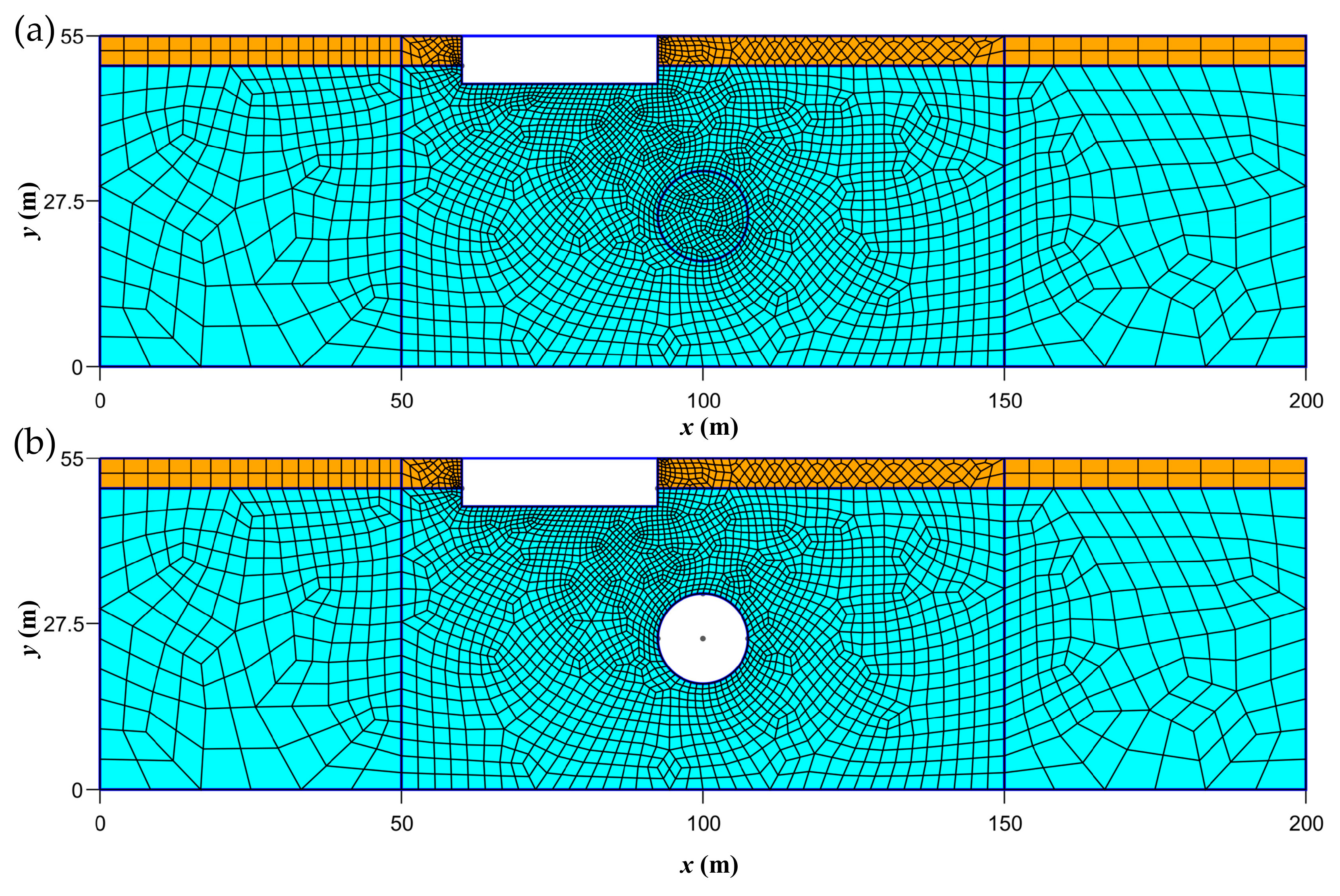
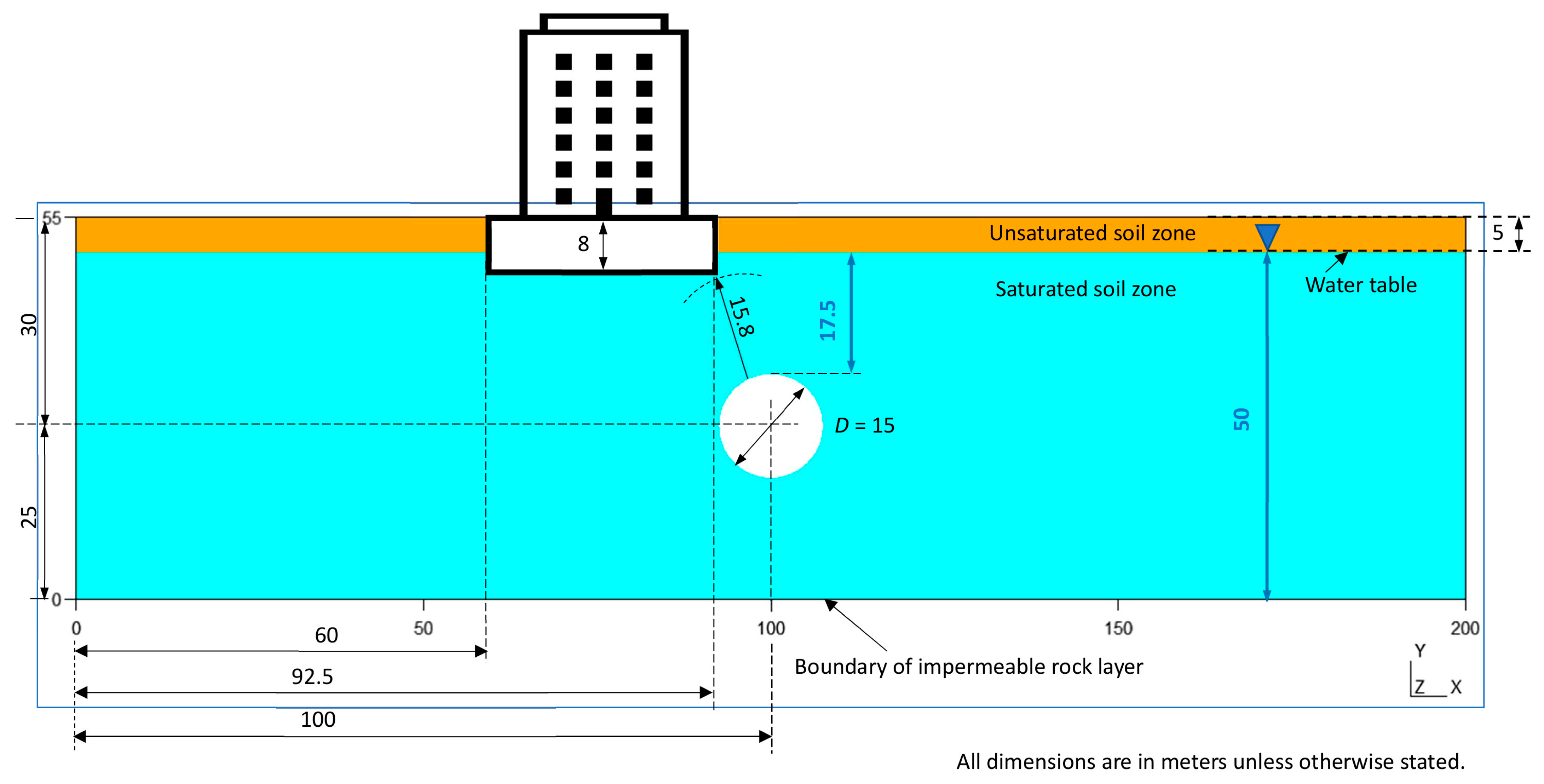
Terzaghi’s principle states that when stress is applied to a porous material, it is opposed by the fluid pressure filling the pores in the material [10,49]. To solve the problem, a FEM model coded in MATLAB was used, so it allows solving the three considered states (Section 2.1). Terzaghi’s principle employs the bulk modulus, Ks, of a material, and it can be defined as [56,58]:
K s = E 3 1 2 ν
where E represents the soil’s Young’s modulus and ν is the Poisson’s coefficient. It is important to clarify that, since we are not working under oedometric conditions but rather under a 2D plane strain assumption, E cannot be equated to D (oedometer modulus or constrained modulus) [56]. This is because the model used allows deformation in any direction, in x or y [31]. The values of Young’s moduli will be assimilated to Esk, which is the Young’s modulus referring to their mineral skeleton obtained in the laboratory. This is acceptable, considering the geological uncertainty, however, assimilating E to D (constrained modulus) means a serious error.
The estimation of settlement according to Terzaghi’s principle is obtained as:
Δ ε v o l = Δ ε x + Δ ε y + Δ ε z = 1 2 ν E Δ σ x + Δ σ y + Δ σ z = 1 K s Δ σ o c t
where Δ σ o c t is the effective octahedral stress tensor and Δ ε v o l is the tensor of volumetric strains. Equation (13) was solved in a stationary way as an elastic problem coupled with a porous media flow problem. Equation (13) predicts that volumetric deformation only occurs due to variations in normal octahedral stress [58]. Therefore, there are only deformations, but no distortions, so the shear strength is not involved in the formulation, nor is the shear modulus, G [56,58]. Thus, the shear strength should never appear in Terzaghi’s formulation for calculating settlement due to variations in effective stress (Section 3.2). Equation (13) does not predict shear failure of the soil, with or without cohesion, nor under drained or undrained conditions. This formulation estimates an additional settlement, induced by groundwater inflow into a tunnel, in addition to the elastic or elastoplastic settlement of the ground, due to the variation in effective stress.

2.4. Study Case

The study case refers to the type of cross-section, as shown in Figure 4, with eight load steps (i.e., 0.10, 0.20, 0.30, 0.40, 0.50, 0.60, 0.70, and 0.80 MPa) and four different typical granular soils (Table 1). These load steps have been expressed in unit terms, i.e., they are considered to be applied to a unit horizontal surface determined by 1 m along the direction of the mat foundation and by 1 m in the direction of the tunnel axis. The value of the final load (i.e., 0.80 MPa) is high, and it may exceed the permissible limit for granular soils in the study case [38,39]. Nevertheless, since it is also intended to analyse the effect of the load in settlement with and without tunnelling, it was necessary to reach this level of the load intensity. The hypotheses framing the case study are as follows: (i) Steady flow in porous media. (ii) For each analysis sub-variant, the hydraulic conductivity (k) of the granular soil layers is uniform and identical in the x and y directions. (iii) The constitutive material of the soil layers is cohesionless granular, with a non-limiting porosity index of the effective stress. (iv) Settlement of any type happens over a short period, and thus, deformations are elastic. (v) The tunnel, which is permeable around its whole perimeter, is at atmospheric pressure inside and immediately evacuates any infiltrated flows, so it does not experience hydrostatic pressure from inside. (vi) The granular soils rest on an impermeable rock layer. (vii) The aquifer is instantaneously recharged from the lateral boundaries without any limitation of flow discharge.
Some of the assumptions, although harsh, can be relaxed provided that the procedure was followed involving the three methodological states (Figure 1). The supposed soils (Table 1) were four types of granular soils, with the parameters defined by Terzaghi for each typical soil [54]. The E (Young’s modulus of soil) and ν (Poisson’s ratio), which are not detailed for soil types in [54], correspond to mean values from Spanish technical regulations on buildings [39], based on the Eurocode EC-7 [38]. The model for the case study allows complete freedom of deformation in 2D, so it is not convenient to use laboratory parameters obtained under constrained conditions.
It was necessary to adopt a soil deformation model for granular soils. In non-cohesive granular soils without mixtures of silt or clay, within a certain interval there is linearity of deformation due to initial stress, resulting in immediate and elastic deformation [56]. In constrained conditions, in elastoplastic models [27], it is possible to model the soil behaviour using parameters from laboratory oedometer conditions. Nevertheless, due to the scope of this work and to optimize the potential of the presented methodology (Section 2.1), it was not implemented in oedometer nor constrained conditions. It allows assessing the decompressions in the tunnel invert and the stress in the horizontal axis (Section 3.2). The constitutive relationship used was elastic type and not limited by effective stress. With this type of constitutive model, the nonlinearity of settlement due to Terzaghi’s principle can be demonstrated without interference.
The study case refers to a prototypical situation that includes some flexibility and geological uncertainty. It is inspired by some types of soil, materials, and the rise of the water table (at certain times of the year) present in some reaches of the M-30 orbital motorway (Madrid). The assumed tunnel diameter of 15 m (Figure 4) corresponds to that of the tunnel boring machine Dulcinea, which was one of the largest in the world. It was used in tunnels of the above-mentioned M-30. The comparison of the results with models in oedometric conditions is not satisfactory because, among other considerations, they do not allow for evaluating the uplift of the tunnel. However, the ground’s subsidence has been monitored [60]. The diameter of 15 m chosen for the tunnel (Figure 4) is appropriate to evaluate Terzaghi’s principle with consideration of the effect on the differential settlement of buildings, both in the area influenced by the tunnel and on the contour of the tunnel itself.

3. Results and Discussion

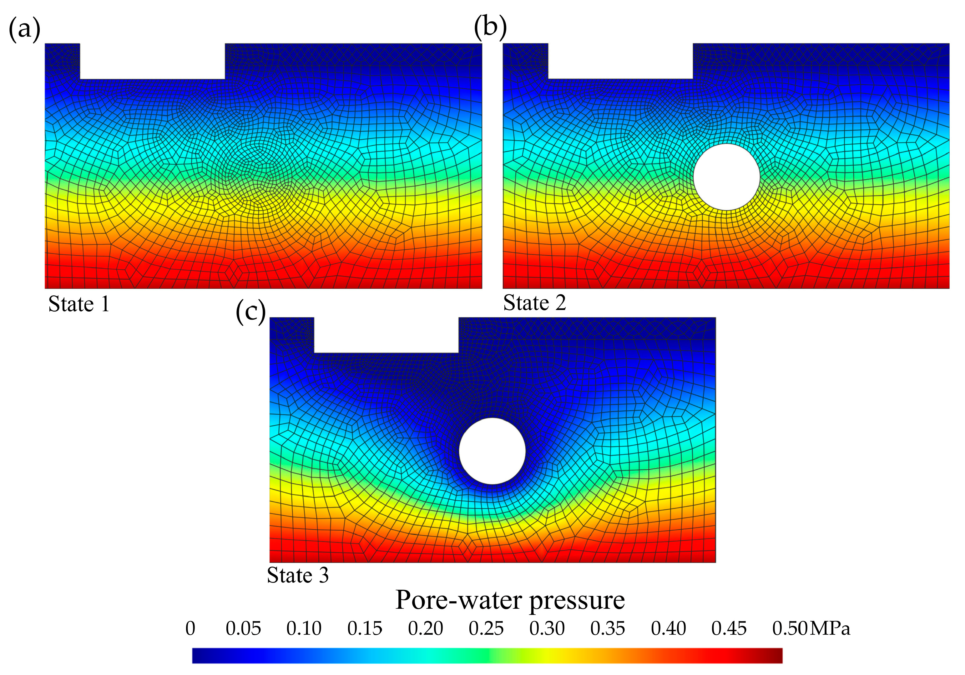
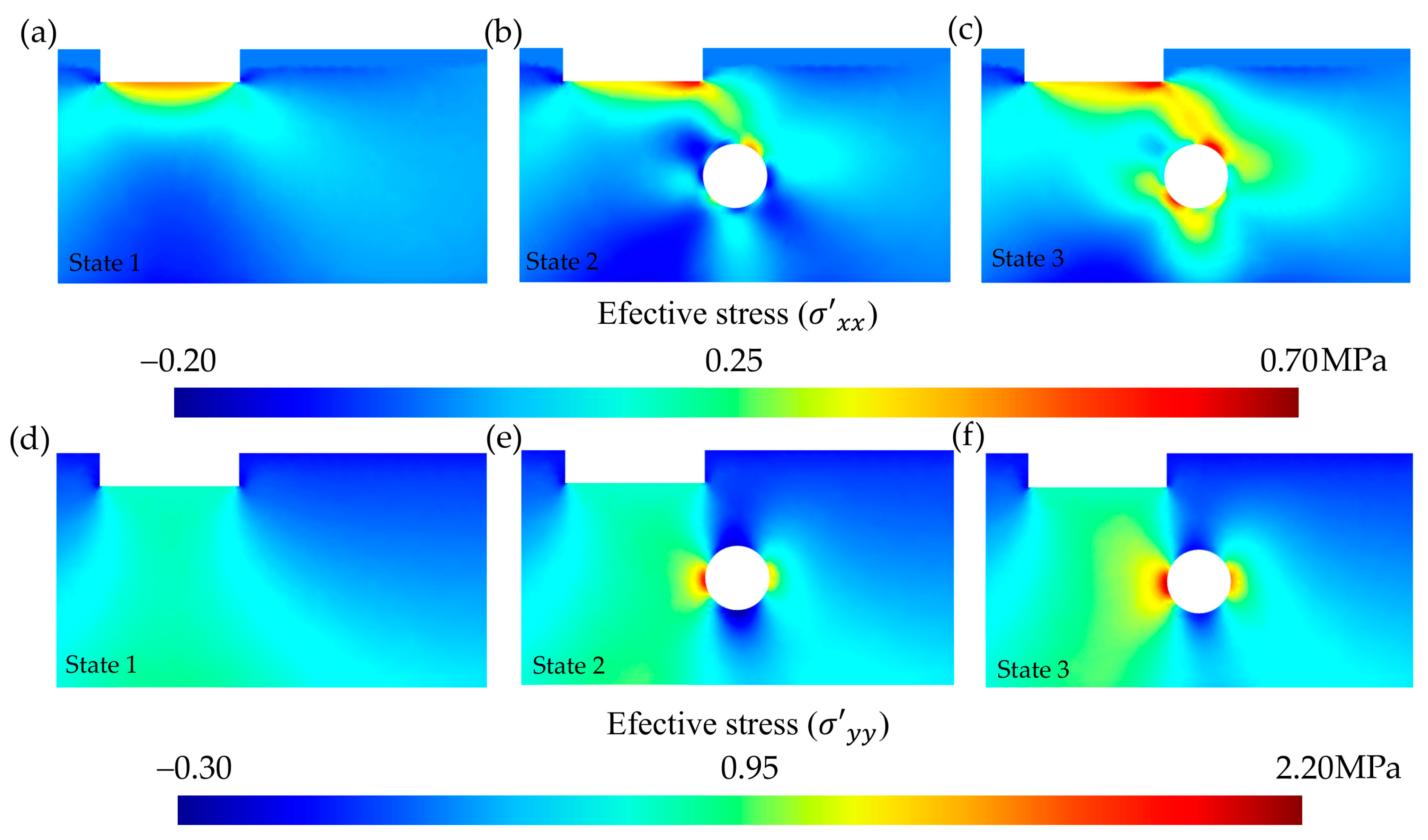
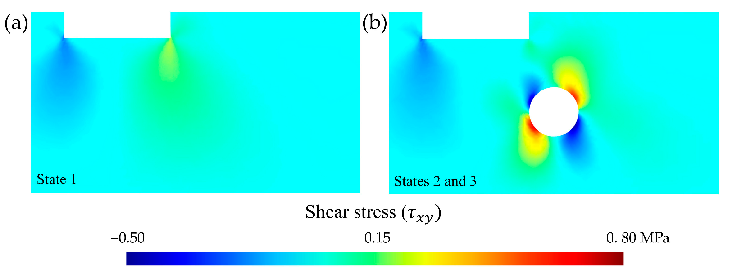
3.1. Effective Stress for the Three Methodological States

The model was applied to four types of granular soils, covered by the case study (Table 1). Results for each of the nodes that compose the mesh were obtained for each type of soil. Additionally, a total of eight steps were established for the ground load process. Data from preeminent selected nodes are shown in Table 2. To illustrate the results related to a singular value of effective stress, the two extreme values of the series of load steps were selected: the first or initial step (q = 0.10 MPa) and the last or final step (q = 0.80 MPa). Displayed results in Table 2 represent a selection of soil type 4 (i.e., mixed-grained sand, dense: the most rigid from the four analysed soils) [54,56]. The locations of nodes used to show the results of Table 2 correspond to the crown and invert of the tunnel, and to the mat foundation’s extremes with the lowest elevation. These nodes themselves are sufficient to illustrate the need for the three methodological states (Figure 3) of the applied procedure (Figure 1).
It can be observed that the results of effective stress significantly varied between the three states for the nodes located in the crown and on the invert of the tunnel. These also varied, although were more subdued, in the nodes located at the extremes of the mat foundation. This is because the stress state of the ground before and after the tunnel varied (Table 2, State 1 2), even when the tunnel was at 15.8 m from the nearest node of the mat foundation, without infiltration occurring inside it. When the soil was excavated to open the tunnel, passing from state 1 to state 2, the values of total stress in the ground were altered, even without considering vibrations generated by the construction method [8], nor hypothetical dynamic loads due to vibrations in the operation stage [5,61]. Since effective stress was equal to total stress minus pore-water pressure [31], effective stress was altered, even though the pore-water pressure did not vary between states 1 and 2 due to no change in the hydraulic head as there was no inflow within the tunnel [42]. Therefore, states 1 and 3 cannot be directly compared to estimate the settlement caused exclusively by the variation of effective stress due to infiltration into the tunnel. Hence, state 2 is required as an initial reference. In state 2, with respect to state 3, the effective stress values were not distorted by tunnelling, since both states (2 and 3) already include the tunnel. Regarding the elastic settlement of the soil due to tunnel construction, in this case without considering the hydraulic processes, state 1 is necessary as it is the basic reference for the initial stress state prior to tunnelling. Its necessity in the methodology is due to the sequential variation in the total stress of the three states caused by the tunnel construction. Based on the above, the need to establish three states (and not only two) to a proper estimation of the total settlement due to tunnelling is considered justified and unavoidable. The developed code integrates flow phenomena in a porous medium with the elastic problem, taking into account the three methodological states.

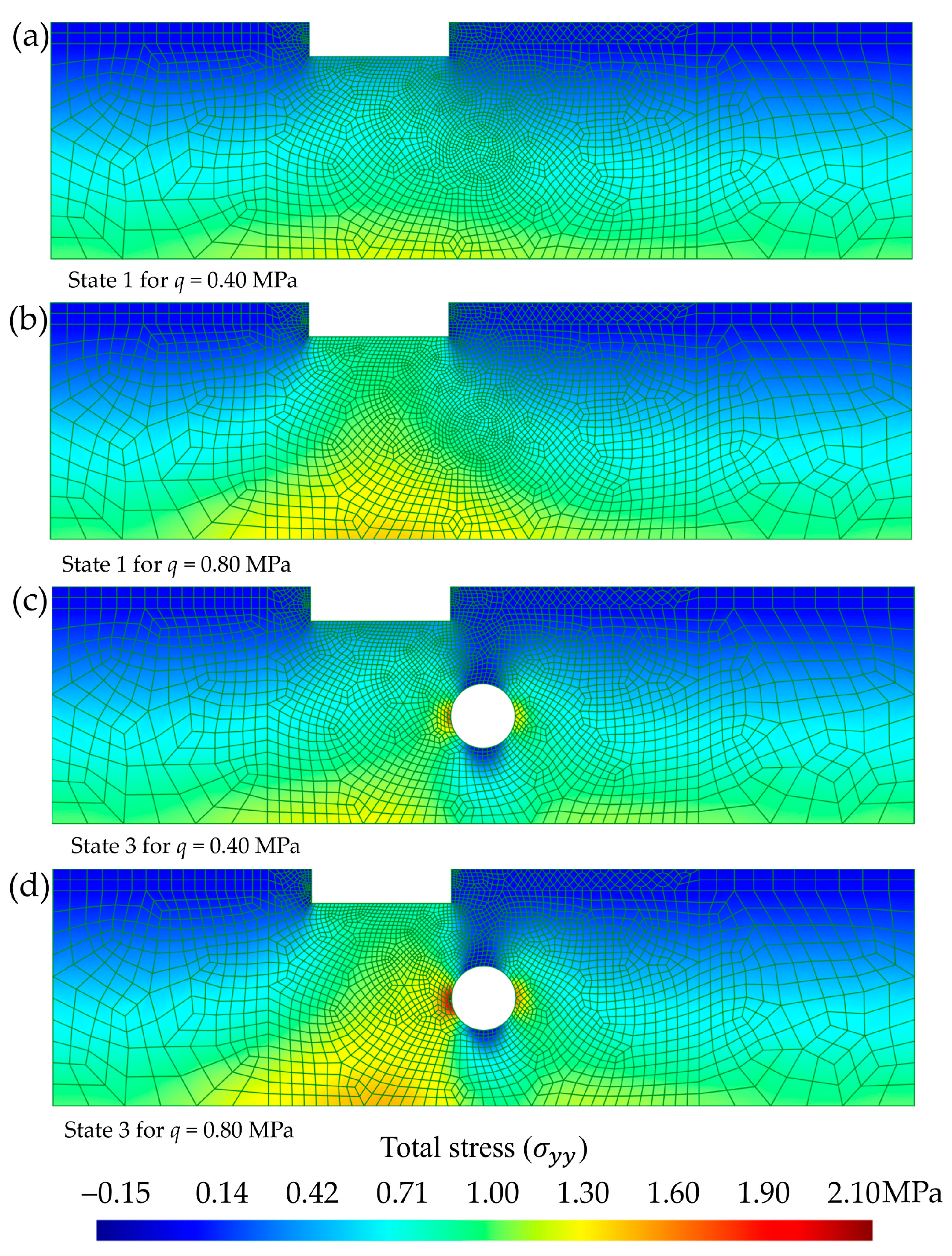
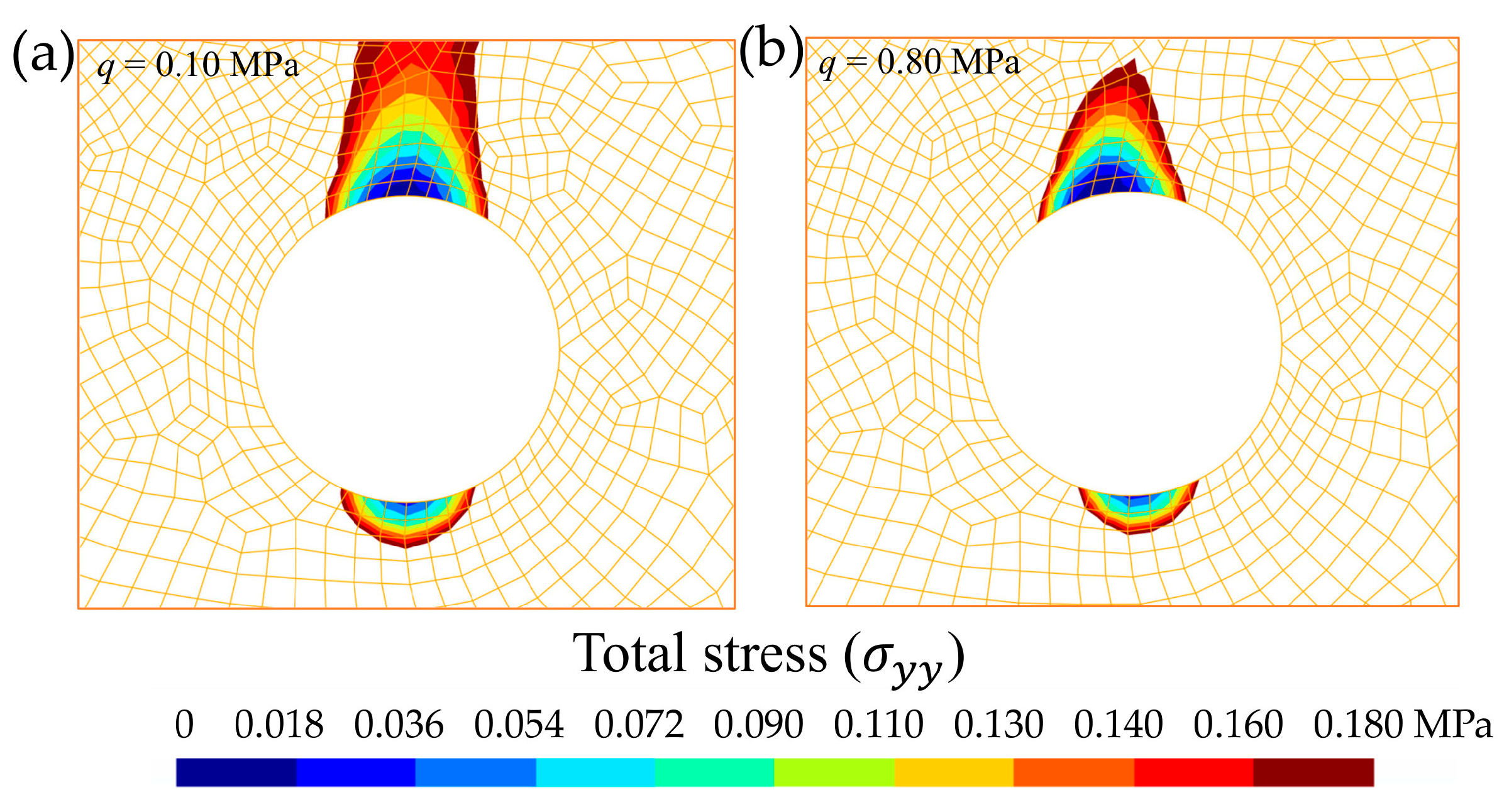
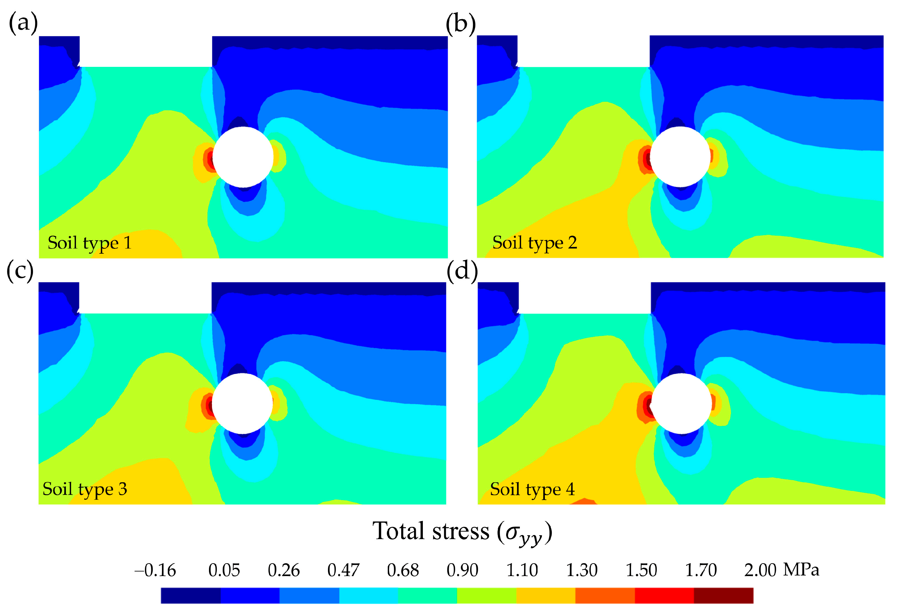
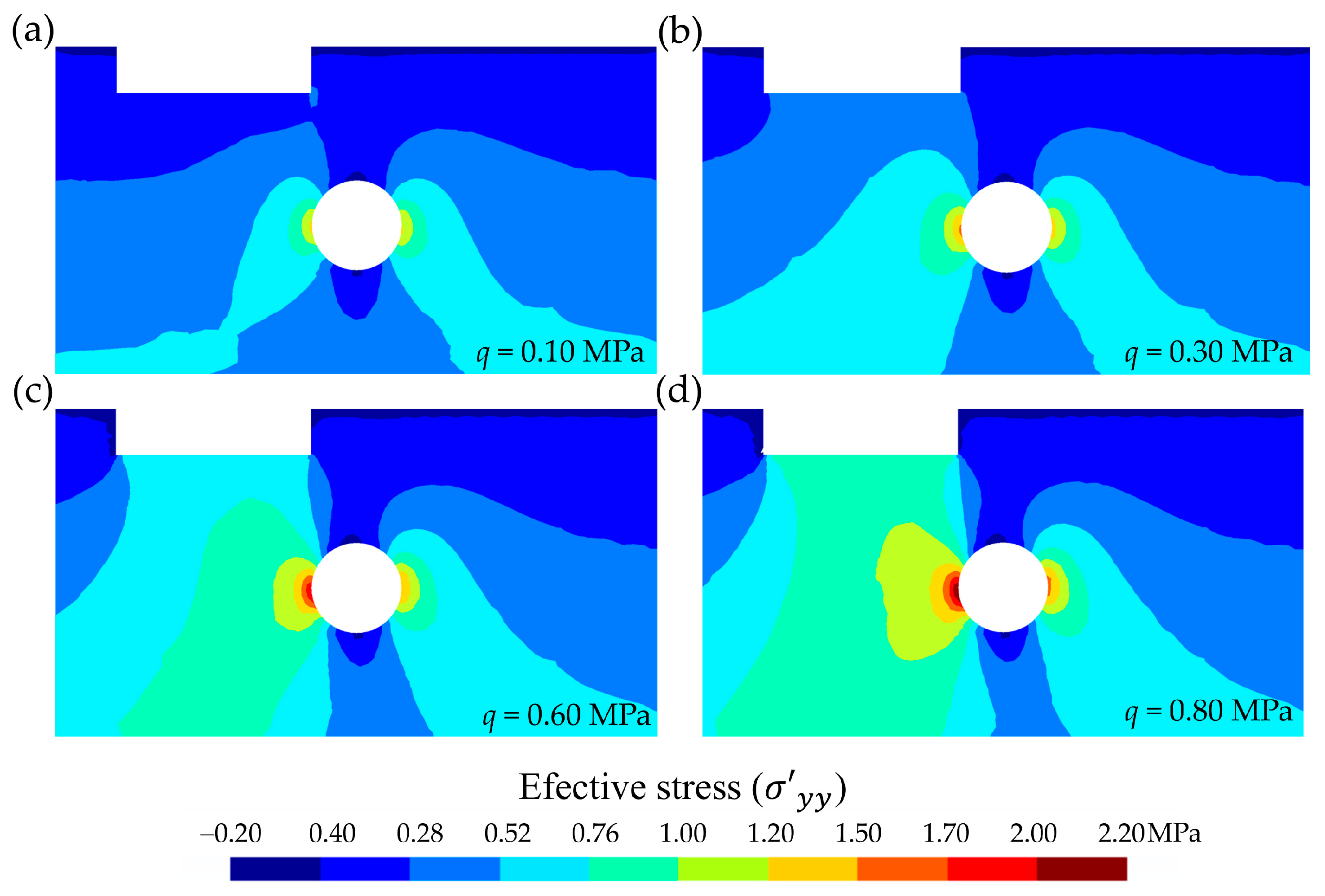
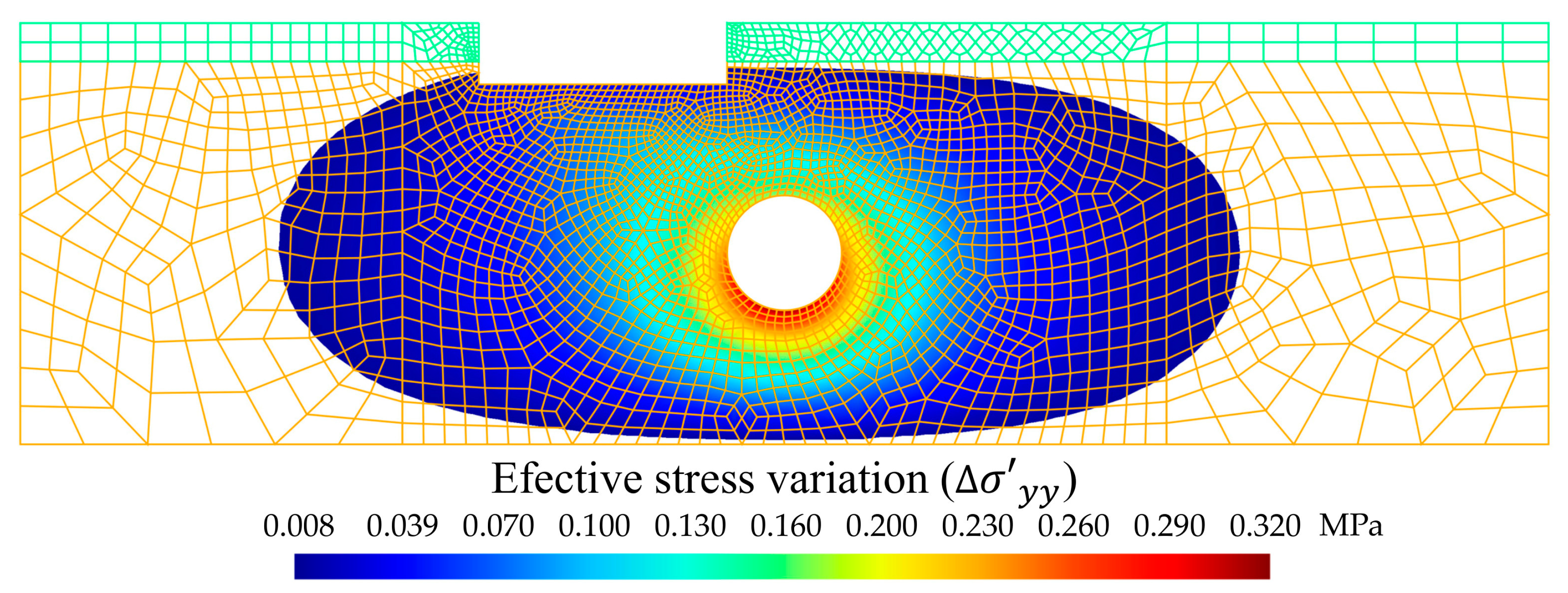
3.2. Total Stress and Effective Stress in the Domain

To detect the soil sensitivity to loads transmitted by the foundation, the total stress, σ y y , was selected with two extreme load steps (q = 0.40 MPa and q = 0.80 MPa) and for two states (without tunnel (state 1) and with tunnel and groundwater inflow (state 3)). In all the above combinations, only soil type 4 (i.e., mixed-grained sand, dense) has been considered. Since trends analogous to those described above, maintaining the proportions, were observed for the other three soil types, these were not included in the comparison. The effect of the foundation load on the stress state of the ground can be observed in Figure 5.
The effect of loads transmitted by the foundation was clearly observed, with and without the tunnel. Before the tunnel, the loads expanded and gradually distributed as the depth increased following a nonlinear law. The elastic isobaric model of the pressure bulb would focus on the area near the mat foundation [56]. However, for the whole domain established by the study case (Figure 2), it was necessary to evaluate a cross-sectional area extending up to the impermeable rock layer, and the numerical model applied was advantageous. In the FEM used, the nodes of the lower elements not only supported the loads transmitted by the foundation through the nodes of the upper elements, but also the self-weight of the ground and the water table. Therefore, the maximum stress without the tunnel was reached for q = 0.80 MPa, with a value of around 1.4 MPa at a level of −55 m, in contact with the lower impermeable rock layer. However, when the tunnel was constructed, the maximum stress also occurred for q = 0.80 MPa, but in this case, it was located on the left tunnel side with a value of around 2.15 MPa. This critical circumstance must be considered in the tunnel support design.
Selecting a range of stress between 0 MPa and 0.18 MPa (Figure 6), a dangerous decompression was detected in the invert and the tunnel crown. The areas affected by this decompression around the tunnel occurred practically independently of the load value on the mat foundation. Therefore, proper support measures must be taken to prevent tunnel collapse [62,63]. This decompression in the invert and tunnel crown favours the collapse of tunnels excavated in saturated sandy soils [64]. Analysing the invert of the tunnel, especially for type 1 soils, the decompressions in the tunnel contour and the infiltration flows suggest the possibility of a liquefaction of the sands. In the case of using segments in the tunnel lining, the joints must be treated with a specific fibre-reinforced concrete [65,66], suitable for the type of soil (particularly in mining tunnels) [67,68], or water-repellent additives [40].
It was observed that in the less compact soils (Figure 7a,c), the decompressed zones in the contour and adjacent areas of the crown and invert tunnel were somewhat larger. The impact of this on tunnel collapse has already been discussed above. Moreover, if the sandy soils were poorly compacted, to avoid collapse, the lining must be continuous [69]. On the other hand, in the more compact soils (Figure 7b,d), the total stress in the left and right sides of the tunnel was clearly higher. These effects may be due to differences in the stiffness of the mineral skeleton (Esk) of each type of compared soil [70]. For soil type 4 (i.e., mixed-grained sand, dense [54]), the stress in the left side of the tunnel reached 2.11 MPa, while in the right side it reached only 1.55 MPa.
The tunnel construction generated a variation in the initial water level, and thus a water drawdown was induced by the tunnel excavation [42]. It follows that there will be a variation in the effective stress. This variation occurred in all four types of selected soils, depending on the load step, as illustrated for the case of soil type 4, selecting four load steps (0.10, 0.30, 0.60, 0.80 MPa) for the effective stress, σ y y (Figure 8).
It was observed that the load increment did not significantly affect decompression of the crown and the tunnel invert. However, it did significantly affect the state of stress in the left tunnel side, and to a lesser extent in its right side. The effective stress reached a maximum of 2.11 MPa in the left side and 1.55 MPa in the right for a load step of q = 0.80 MPa. When comparing the total stress for soil type 4 and a load step q = 0.80 MPa (Figure 6d), and its corresponding effective stress value (i.e., for the same soil type and load step) (Figure 7d), they did not exactly match, except at the tunnel contour and in the unsaturated moisture zone. This is reasonable because: (i) At the tunnel contour after stabilizing the groundwater inflow into the tunnel, the effective stress value (i.e., total stress minus pore-water pressure) coincided with the total stress value since the pore-water pressure was equal to the atmospheric pressure inside the tunnel according to the hypothesis for state 3 (Section 2.4). (ii) The unsaturated moisture zone is outside the flow problem, since minor suctions were neglected, and therefore the total pressure before and after the groundwater inflow into the tunnel coincided.
Regarding the effective stress, σ x x , except for the tunnel contour, its values differed from the total stress. This is because the model does not work under oedometric conditions, allowing for deformations in both the x and y directions within the restrictions of the 2D plane strain deformation analysis [58]. However, as shown for soil type 4 and a load step q = 0.80 MPa (Figure 9), the maximum stress values were of an order of magnitude lower than the maximum σ y y values. The maximum was obtained for state 3 with a value of 0.7 MPa. The influence of the tunnel was evident in the effective stress for the x-axis: all three states entailed changes in its value. The most unfavourable situation for σ x x occurred with inflow into a drained tunnel (state 3). For σ y y with a tunnel and without groundwater inflow into the tunnel (state 2), the most unfavourable case is presented associated with decompression of the tunnel crown and the invert (0.35 MPa). The maximum compressions were observed for state 3 in the left tunnel side, with very high values, close to 2.15 MPa. In conclusion, although oedometric conditions are suitable for certain cases [56], it is not convenient to model the support system of a tunnel under oedometric conditions due to the presence of non-negligible σ x x values, as well as significant decompression values in σ y y , particularly in the crown and the invert. Similar trends to those described above, maintaining the proportion, were observed for other load steps and soil types.
Regarding the shear strength, τ x y , values of the total stress and effective stress remained constant. In state 1 (no tunnel), because there was no inflow into a tunnel, the hydraulic head was stable and there was no fluid particles’ movement within the porous media. Concerning the case with a tunnel and without groundwater inflow into the tunnel (state 2), and that with inflow into the tunnel (state 3), the results were basically the same. This is due to the consideration that the water flows into the tunnel with a very low velocity [59]. From the results of the shear strength, the following were selected to illustrate the previous comments in Figure 10: no tunnel (state 1) and tunnelling (state 2 and 3) situations were compared for soil type 4 and a load step q = 0.80 MPa.
Shear strength only caused distortions [58], since the xy components ( τ x y ) of the total stress tensor before and after tunnelling were not affected by the pore-water pressure. It was found that the most unfavourable situation with respect to shear strength occurred after tunnelling at the nodes located on the tunnel contour in a direction of π/4 rad with respect to a horizontal plane, taking the centre of the tunnel cross-section as a reference. This is important for assessing the tunnel heading stability (Section 2.1). Shear stress must be considered to evaluate the risk of collapse in granular soils, since for this type of soil, with low or no effective cohesion, tunnel stability is governed by shear strength, and excavation requires a shield [63].
From the previous results and from the results matrices, it was verified that the greatest variation in the effective stress occurred in the contour of the tunnel (Figure 11), with a value of around 0.32 MPa on the invert. The relationship of Terzaghi’s principle Equation (13), apparently linear, considering the soil type and nodal analysis, was visualised in the FEM as a nonlinear law. This nonlinearity was manifested in the foundation settlement (Section 3.3). Linear models for settlement calculations are valid in numerous contexts [30], but this is not the case for mat foundations with a tunnel in their vicinity.
From the above, a question of interest arises: to establish an area of influence of settlement predicted according the Terzaghi’s principle [54]. By setting 8 kPa (2.5% of the total variation) as the minimum value of effective stress variation in y, a zone was obtained that significantly extended around the tunnel (Figure 11). The area of influence extended between eight and nine times the radius of the tunnel on each side. This zone exceeded some of the usual distances considered safe [5,61,71]. The high extension is a consequence of the flow established in a medium where permeability is not questioned. In turn, it is not a symmetrical area, but this is due to the eccentric position of the mat foundation with respect to the tunnel centre. It has a greater extension in the load zone of the mat foundation. It is noteworthy that the extension of the area of influence is invariant to the type of granular soil. This is true if a constant soil hydraulic conductivity and a steady groundwater inflow into the tunnel are guaranteed.

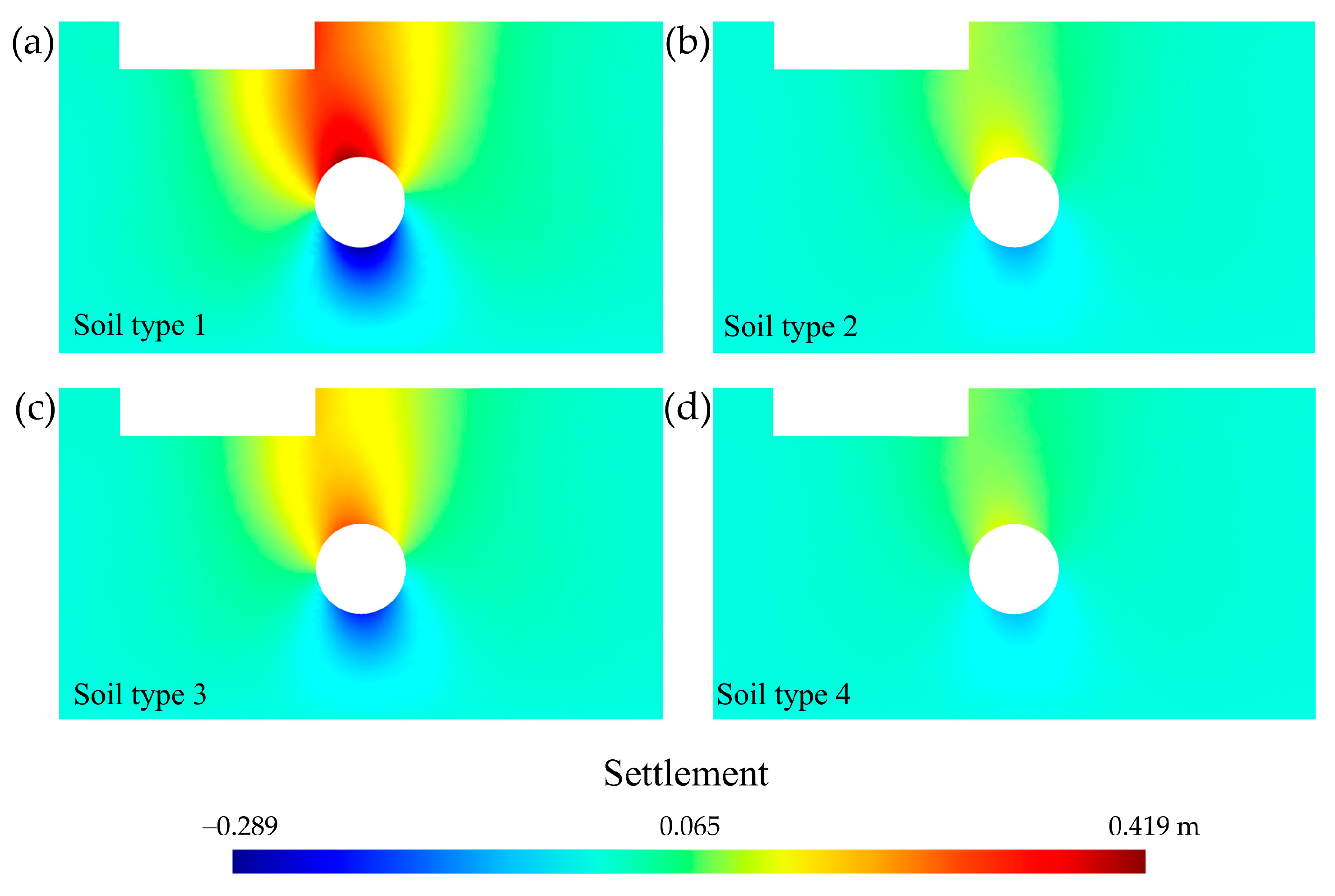
3.3. Field of Displacement and Settlement

The displacement field generated by the tunnelling in non-oedometer conditions has possible displacement in both x and y directions. The greatest displacement occurred for soil type 1 due to its greater weakness in its mineral skeleton [56]. By operating with the displacement of states 1 and 2 (taking > 0 as the settlement directed towards the underlying rock layer and <0 as the settlement produced in the opposite direction), it was possible to obtain the vertical settlement due to the tunnelling without considering the groundwater inflow into the tunnel for the four soil types and the maximum load step q = 0.80 MPa (Figure 12). This settlement has complete freedom of sign, which allowed us to evaluate collapse due to decompression [72]. Tunnel uplift can be induced by a collapse of the tunnel invert due to decompression. This decompression, as seen in Section 3.2, is favoured by groundwater inflow into the tunnel. This type of collapse, the causes of which can be diverse and favour movement and even uplift in lined tunnels [73], has led some countries, such as Spain, to establish technical guidelines to avoid it [74].
The soil effect is crucial in the settlement of a mat foundation [17], but also the tunnel’s boundaries [5,18]. Loose soils (soil types 1 and 3, Figure 12a,c) present a larger settlement in both vertical directions, including downward in the mat foundation and in the tunnel crown, and also upward in the invert. The mixed granulometries (soil types 3 and 4, Figure 12c,d) present less settlement than the uniform sands for the same degree of compaction (soil types 1 and 2, Figure 12a,b).
To obtain settlement caused by groundwater inflow into the tunnel, the following procedure was carried out. First, Terzaghi’s formulation was applied, considering variations in effective stress [54]. In doing so, the analysis was not conducted under confined oedometer conditions, but rather allowed for deformation in the x and y directions of the strain tensor. Only changes in the elemental volume occurred because the variation in effective stress only involves octahedral stress. There was no distortion due to Terzaghi’s principle, only changes in volume. Second, in the 2D plane strain deformation analysis [58], each node was evaluated to obtain the settlement, allowing freedom to reach positive or negative vertical displacement. In this way, it is possible to detect that the effect of the Terzaghi’s principle (due to groundwater inflow into a tunnel) on the tunnel invert is unfavourable (in a similar way to the elastic settlement due to tunnel construction), which increases the risk of collapse [69,72].
To illustrate this settlement due to groundwater inflow into the tunnel, the four soil types were combined with the maximum load step q = 0.80 MPa (Figure 13). Since settlement by the Terzaghi’s principle was lower than those in Figure 12 and considerably varied depending on each soil type, isolines with different scales have been used for loose or dense soils.
It was distinguished that there was an influence on the settlement due to groundwater inflow into the tunnel on the mat foundation. Additionally, this influence was not uniform throughout the mat foundation surface contact, nor was it linear with respect to the load step. This is explained in detail in Section 3.4. Therefore, this influence will generate a differential settlement, with dangerous consequences and limitations according to regulations in the field of building foundations [38,39]. The loose soils (soil types 1 and 3, Figure 13a,c) are more prone to settlement due to Terzaghi’s principle, as well as to elastic settlement due to tunnelling, although there is no linearity (Section 3.3). It can be observed that the effect of groundwater inflow into the tunnel was ostensible, even in the most compact soils (soil types 2 and 4, Figure 13b,d). The mixed granulometries (soil types 3 and 4, Figure 13c,d), with the highest bulk modulus, also had lower settlement for the same degree of compaction than the uniform granulometries of sands. Therefore, settlement due to groundwater inflow into the tunnel cannot be neglected in any of the four types of soil studied.
However, the most noteworthy aspect is that, as mentioned above for settlement due to tunnelling, the oedometric conditions were not suitable for modelling and quantifying settlement by Terzaghi’s principle. The effect of groundwater inflow into the tunnel, according to this principle, increased the decompression in the tunnel crown and the invert. If confinement conditions were imposed on a soil–structure interface, a contradiction would arise, since in the zone of the tunnel invert, even by decreasing the effective stress in an upward direction, the settlement would be downward, which is counterfactual. Therefore, it is necessary to work under non-oedometric conditions to properly evaluate the effect of groundwater inflow into a tunnel in order to determine tunnel settlement due to the Terzaghi effect.
From the analysis of the minimum and maximum load steps of the case study (i.e., 0.10 MPa and 0.80 MPa), the results of Table 3 are presented, taking the soil with less settlement values (soil type 4).
Regarding the mat foundation, a differential settlement without infiltrations: δ d 0 y = 3.96 cm of q = 0.10 MPa, and δ d 0 y = 7.39 cm of q = 0.80 MPa, was deduced, as well as a differential settlement with infiltrations: δ d y = 4.10 cm of q = 0.10 MPa, and δ d y = 7.63 cm of q = 0.80 MPa. This settlement increased in soil types 1, 2, and 3. Therefore, it can be verified that even for soils with a less open-structured mineral skeleton and for the smallest load step considered, the settlement due to groundwater inflow into the tunnel was not negligible. This settlement due to groundwater inflow into a tunnel constituted around 11–35% of the total settlement for the tunnel crown and the invert, depending on the degree of compaction, the load, and the type of soil. For type 2 and 4 soils, the settlement due to the Terzaghi principle for the maximum load reached up to 12% of the total settlement. For type 1 and 3 soils, the settlement due to the Terzaghi principle for the maximum load reached 35% of the total settlement, which is critical. In the mat foundation, the settlement was between 4% and 12% of the total settlement, depending on the degree of compaction, the load, and the type of soil. Settlement due to the Terzaghi principle, with 12% of the total, occurred in type 1 soil, with the most uniform grain size distribution and the lowest degree of compaction of the four soils compared here. If we consider the differential settlement of the mat foundation, the additional settlement caused by groundwater inflow into the tunnel generated increases above 12%. The values of the settlement considerably increased as the soils became more open-structured and with grain size distribution without gravels. Therefore, settlement and differential settlement due to groundwater inflow into a tunnel must be considered in the case under study.

3.4. Sensitivity Analisys of the Mat Foundation Settlement

Table 4 shows the sensitivity analysis results of the effect of the eight load steps in the nodes’ settlements belonging to the mat foundation. Table 4 includes the settlement due to Terzaghi’s principle in relevant nodes for the four types of soil and for a selection of the eight load steps.
The non-oedometric linear elastic soil constitutive model predicted that the settlement due to Terzaghi’s principle would adopt a nonlinear elastic behaviour with hardening. To illustrate this, Figure 14 represents the settlement according to Terzaghi’s principle and the total values for each load step and for soil type 4 (the most rigid).
From Table 4 and Figure 14, the existence of a foundation’s settlement can be seen. The model follows a nonlinear law with respect to the x coordinate of each node of the mat foundation, whether it concerns partial or total settlement. Furthermore, it can be observed that there was a proportional relationship between the elastic settlement of the ground and the settlement resulting from groundwater inflow into a tunnel (i.e., in accordance with Terzaghi’s principle), which remained consistent over the entire load step range. However, there was no linearity between the load and the settlement, although it was evident, as expected, that higher loads resulted in greater settlements. For example, for soil type 4, the load step/settlement ratio varied from 30.6 MPa/m for q = 0.10 MPa to 22.50 MPa/m for q = 0.80 MPa. A phenomenon of soil hardening appeared, which showed that a doubling of loads does not imply a doubling of settlement, with the value in that case being lower. However, settlement caused by tunnelling in the tunnel’s own perimeter requires a corresponding support system [61,62,63]. A tunnel’s collapse would establish mechanisms of soil failure that would configure a new case study.

4. Conclusions

In correspondence with the objectives and results, it is concluded that: (i) For a proper settlement estimation due to Terzaghi’s principle, a minimum of three methodological states needs to be applied to the model. Therefore, the initial state 1, before tunnelling, state 2, subsequent to the tunnelling without groundwater inflow into the tunnel, and state 3, after tunnelling and with stabilised groundwater inflow into the tunnel, were applied. (ii) It is not recommended to model under oedometer conditions in order to properly detect the possible collapse due to the uplift of the tunnel invert, which was favoured by the decompression and enhanced by groundwater inflow into the tunnel. Moreover, under non-oedometric conditions and allowing for deformations in both the x and y directions, a thorough assessment of settlement in the tunnel crown and the invert can be achieved. (iii) After applying the model combining four types of coarse-grained soil with eight load steps, it was determined that the loads had a nonlinear effect on the value of partial, total, and differential settlements. It was estimated that the settlement due to Terzaghi’s principle was bounded by 11–35% of the total settlement predicted in the tunnel perimeter. It is recommended for geotechnical designers to take into consideration the serious problem of tunnel uplift in loose granular soils with a water table above the tunnel head. The settlement due to Terzaghi’s principle represented up to 12% of the mat foundations’ total settlement. Engineering and architectural practitioners should not ignore settlement due to Terzaghi’s principle, even in compact terrain. (iv) The total stress in the x direction, even if of a lower magnitude than the stresses in the y direction, is not negligible. Thus, for the purpose of the strength calculation of the tunnel support systems, it is also not feasible to model the behaviour of the soil under oedometer conditions. (v) The influence area of the settlement due to the variation in pore-water pressure can extend up to nine times the tunnel radius on both sides of its centre, thus exceeding some of the established safety distances.

Author Contributions

Conceptualisation, C.A.R.; methodology, C.A.R. and Á.M.R.-P.; software, C.A.R.; formal analysis, C.A.R., Á.M.R.-P. and R.L.; investigation, C.A.R. and R.L.; resources, C.A.R. and Á.M.R.-P.; data curation, Á.M.R.-P., J.J.C.-M. and R.L.; writing—original draft preparation, C.A.R. and R.L.; writing—review and editing, R.L. and C.A.R.; visualisation, C.A.R., R.L., Á.M.R.-P., J.J.C.-M. and J.A.H.-T.; supervision, R.L.; project administration, C.A.R. All authors have read and agreed to the published version of the manuscript.

Funding

This research received no external funding.

Data Availability Statement

Data are contained within the article. The tool files used for this study are available upon request from the corresponding author.

Acknowledgments

The authors would like to thank Deryck J. Barker Fraser for the translation of the manuscript. Comments by two anonymous reviewers were extremely helpful in improving the manuscript. The third author acknowledges the support of the Catalan Government through the Fluvial Dynamics Research Group (2021 SGR 01114).

Conflicts of Interest

The authors declare no conflict of interest.

References

  1. Muhammed, T.A.; Karim, F.R. The Influence of Drop Panel’s Dimensions on the Punching Shear Resistance in Ultra-High-Performance Fiber-Reinforced Concrete Flat Slabs. Construction 2022, 2, 55–65. [Google Scholar] [CrossRef]
  2. Coduto, D.P.; Kitch, W.A.; Yeung, M.R. Foundation Design, 3rd ed.; California State Polytechnic University: Pomona, CA, USA, 2016; pp. 3–4, 401–418. [Google Scholar]
  3. Yun, B.; Yang, Z.; Jiang, Z. Key protection techniques adopted and analysis of influence on adjacent buildings due to the Bund Tunnel construction. Tunn. Undergr. Space Technol. 2014, 41, 24–34. [Google Scholar] [CrossRef]
  4. Boscardin, M.D.; Cording, E.J. Building response to excavation-induced settlement. J. Geotech. Eng. 1989, 115, 1–21. [Google Scholar] [CrossRef]
  5. Zhou, S.; Di, H.; Xiao, J.; Wang, P. Differential settlement and induced structural damage in a cut-and-cover subway tunnel in a soft deposit. J. Perform. Constr. Facil. 2016, 30, 04016028. [Google Scholar] [CrossRef]
  6. Di, H.; Zhou, S.; Xiao, J.; Gong, Q.; Luo, Z. Investigation of the long-term settlement of a cut-and-cover metro tunnel in a soft deposit. Eng. Geol. 2016, 204, 33–40. [Google Scholar] [CrossRef]
  7. Krishna, S.S.; Lokhande, R.D. Study on the Effect of Surface Subsidence Due to Tunneling Under Various Loading Conditions. Geotech. Geol. Eng. 2022, 40, 923–943. [Google Scholar] [CrossRef]
  8. Rallu, A.; Berthoz, N.; Charlemagne, S.; Branque, D. Vibrations induced by tunnel boring machine in urban areas: In situ measurements and methodology of analysis. J. Rock Mech. Geotech. Eng. 2023, 15, 130–145. [Google Scholar] [CrossRef]
  9. Tian, X.; Song, Z.; Wang, J. Study on the propagation law of tunnel blasting vibration in stratum and blasting vibration reduction technology. Soil Dyn. Earthq. Eng. 2019, 126, 105813. [Google Scholar] [CrossRef]
  10. Beben, D.; Maleska, T.; Bobra, P.; Duda, J.; Anigacz, W. Influence of Traffic-Induced Vibrations on Humans and Residential Building—A Case Study. Int. J. Environ. Res. Public Health 2022, 19, 5441. [Google Scholar] [CrossRef]
  11. Rubio, H.; Garcia-Prada, J.C.; Castejón, C.; Laniado, E. Dynamic analysis of rolling bearing system using Lagrangian model vs. FEM code. In Proceedings of the 12th World Congress in Mechanism and Machine Science, IFToMM, Besançon, France, 17–21 June 2007; pp. 205–210. [Google Scholar]
  12. Kontoni, D.P.N.; Farghaly, A.A. Mitigation of train-induced vibrations on nearby high-rise buildings by open or geofoam-filled trenches. J. Vibroeng. 2020, 22, 416–426. [Google Scholar] [CrossRef]
  13. Ruiz, J.F.; Soares, P.J.; Costa, P.A.; Connolly, D.P. The effect of tunnel construction on future underground railway vibrations. Soil Dyn. Earthq. Eng. 2019, 125, 105756. [Google Scholar] [CrossRef]
  14. Umaru, I.; Alkali, B.; Alhaji, M.M.; Alhassan, M.; Adejumo, T.E.; Jagaba, A.H. Structural Design of Field Plate Load Test Equipment to Determine In situ Bearing Capacity and Settlement of Clayey Soil. Construction 2023, 3, 23–39. [Google Scholar]
  15. Guerriero, V. 1923–2023: One Century since Formulation of the Effective Stress Principle, the Consolidation Theory and Fluid–Porous-Solid Interaction Models. Geotechnics 2022, 2, 961–988. [Google Scholar] [CrossRef]
  16. Terzaghi, K. Erdbaumechanik; F. Deuticke & Leipzig U.: Wien, Austria, 1925. [Google Scholar]
  17. Lee, J.; Salgado, R. Estimation of footing settlement in sand. Int. J. Geomech. 2002, 2, 1–28. [Google Scholar] [CrossRef]
  18. Moh, Z.C.; Ju, D.H.; Hwang, R.N. Ground movements around tunnels in soft ground. In Proceedings of the International Symposium on Geotechnical Aspects of Underground Construction in Soft Ground, London, UK, 15–17 April 1996; Available online: http://www.maaconsultants.com/common/publications/1995/1995-021.pdf (accessed on 28 February 2022).
  19. Pinto, F.; Whittle, A.J. Ground movements due to shallow tunnels in soft ground. I: Analytical solutions. J. Geotech. Geoenviron. Eng. 2014, 140, 04013040. [Google Scholar] [CrossRef]
  20. Pinto, F.; Zymnis, D.M.; Whittle, A.J. Ground movements due to shallow tunnels in soft ground. II: Analytical Interpretation and Prediction. J. Geotech. Geoenviron. Eng. 2014, 140, 04013041. [Google Scholar] [CrossRef]
  21. Wang, F.; Gou, B.; Zhang, Q.; Qin, Y.; Li, B. Evaluation of ground settlement in response to shield penetration using numerical and statistical methods: A metro tunnel construction case. Struct. Infrastruct. Eng. 2016, 12, 1024–1037. [Google Scholar] [CrossRef]
  22. Korsawe, J.; Starke, G.; Wang, W.; Kolditz, O. Finite element analysis of poro-elastic consolidation in porous media: Standard and mixed approaches. Comput. Methods Appl. Mech. Eng. 2006, 195, 1096–1115. [Google Scholar] [CrossRef]
  23. Larese, A.; Rossi, R.; Oñate, E. Finite Element Modeling of Free Surface Flow in Variable Porosity Media. Arch. Computat. Methods Eng. 2015, 22, 637–653. [Google Scholar] [CrossRef]
  24. Sandström, C.; Larsson, F.; Runesson, K.; Johansson, H. A two-scale finite element formulation of Stokes flow in porous media. Comput. Methods Appl. Mech. Eng. 2013, 261, 96–104. [Google Scholar] [CrossRef]
  25. Liu, W.K.; Li, S.; Park, H.S. Eighty years of the finite element method: Birth, evolution, and future. Arch. Comput. Methods Eng. 2022, 29, 4431–4453. [Google Scholar] [CrossRef]
  26. Callari, C.; Armero, F.; Abati, A. Strong discontinuities in partially saturated poroplastic solids. Comput. Methods. Appl. Mech. Eng. 2010, 199, 1513–1535. [Google Scholar] [CrossRef]
  27. Callari, C.; Casini, S. Tunnels in saturated elasto-plastic soils: Three-dimensional validation of a plane simulation procedure. In Mechanical Modelling and Computational Issues in Civil Engineering; Maceri, F., Frémond, M., Eds.; Springer: Berlin/Heidelberg, Germany, 2005; pp. 143–164. Available online: https://link.springer.com/content/pdf/10.1007/3-540-32399-6.pdf#page=153 (accessed on 9 March 2022).
  28. Zhang, L.; Wu, X.; Ji, W.; AbouRizk, S.M. Intelligent approach to estimation of tunnel-induced ground settlement using wavelet packet and support vector machines. J. Comput. Civ. Eng. 2017, 31, 04016053. [Google Scholar] [CrossRef]
  29. Burland, J.B.; Burbidge, M.C.; Wilson, E.J.; Terzaghi, K. Settlement of foundations on sand and gravel. Proc. Inst. Civ. Eng. Civ. 1985, 78, 1325–1381. [Google Scholar] [CrossRef]
  30. Maugeri, M.; Castelli, F.; Massimino, M.R.; Verona, G. Observed and computed settlements of two shallow foundations on sand. J. Geotech. Eng. 1998, 124, 595–605. [Google Scholar] [CrossRef]
  31. Jiménez, J.A.; de Justo, J.L. Geotecnia y Cimientos: Propiedades de Los Suelos y de Las Rocas, 2nd ed.; Editorial Rueda: Madrid, Spain, 1975; pp. 181–217. [Google Scholar]
  32. Shi, X.S.; Yin, J.; Zhao, J. Elastic visco-plastic model for binary sand-clay mixtures with applications to one-dimensional finite strain consolidation analysis. J. Eng. Mech. 2019, 145, 04019059. [Google Scholar] [CrossRef]
  33. van Rijn, L.C.; Barth, R. Settling and consolidation of soft mud–sand layers. J. Waterw. 2019, 145, 04018028. [Google Scholar] [CrossRef]
  34. Feng, X.; Gourvenec, S. Consolidated undrained load-carrying capacity of subsea mudmats under combined loading in six degrees of freedom. Géotechnique 2015, 65, 563–575. [Google Scholar] [CrossRef]
  35. Gu, X.; Chen, F.; Zhang, W.; Wang, Q.; Liu, H. Numerical investigation of pile responses induced by adjacent tunnel excavation in spatially variable clays. Undergr. Space 2022, 7, 911–927. [Google Scholar] [CrossRef]
  36. Basile, F. Effects of tunnelling on pile foundations. Soils Found. 2014, 54, 280–295. [Google Scholar] [CrossRef]
  37. Gokuldas, S.; Banerjee, S.; Nimbalkar, S.S. Effects of tunneling-induced ground movements on stability of piled raft foundation: Three-dimensional finite-element approach. Int. J. Geomech. 2020, 20, 04020104. [Google Scholar] [CrossRef]
  38. Gepp, J.E.; de Santayana, F.P.; Martínez, Á.P. Bases del Anejo Nacional Español del Eurocódigo EC-7 (proyecto geotécnico). Hormigón y Acero 2014, 65, 47–62. [Google Scholar] [CrossRef]
  39. Dirección General de Arquitectura, Vivienda y Suelo. Código Técnico de la Edificación. Documento Básico. Seguridad Estructural. Cimientos. CTE-SE-DBSE-C; Ministerio de Fomento. Gobierno de España: Madrid, Spain, 2019; Available online: https://www.codigotecnico.org/pdf/Documentos/SE/DBSE-C.pdf (accessed on 15 March 2021).
  40. Wu, Y.; Dong, L.; Shu, X.; Yang, Y.; She, W.; Ran, Q. A review on recent advances in the fabrication and evaluation of superhydrophobic concrete. Compos. B Eng. 2022, 237, 109867. [Google Scholar] [CrossRef]
  41. Luciani, A.; Peila, D. Tunnel waterproofing: Available technologies and evaluation through risk analysis. Int. J. Civ. Eng. 2019, 17, 45–59. [Google Scholar] [CrossRef]
  42. Su, K.; Zhou, Y.; Wu, H.; Shi, C.; Zhou, L. An analytical method for groundwater inflow into a drained circular tunnel. Groundwater 2017, 55, 712–721. [Google Scholar] [CrossRef] [PubMed]
  43. Dan, M.M.; Tonnizam, M.E.; Komoo, I.; Madun, A.; Talib, M.A.; Ramadhansyah, P.J.; Taib, A.M.; Hasbollah, D.Z.; Yusof, Z.M.; Noorasyikin, M.N. Physico-mechanical characteristics of tropical granite boulders in weathered heterogeneous zones for geotechnical design purposes. Phys. Chem. Earth Parts A/B/C 2023, 129, 103311. [Google Scholar] [CrossRef]
  44. Nikvar, A.; Katibeh, H.; Farhadian, H. Numerical analysis of steady-state groundwater inflow into Tabriz line 2 metro tunnel, northwestern Iran, with special consideration of model dimensions. Bull. Eng. Geol. Environ. 2016, 75, 1617–1627. [Google Scholar] [CrossRef]
  45. Park, K.H.; Owatsiriwong, A.; Lee, J.G. Analytical solution for steady-state groundwater inflow into a drained circular tunnel in a semi-infinite aquifer: A revisit. Tunn. Undergr. Space Technol. 2008, 23, 206–209. [Google Scholar] [CrossRef]
  46. Yoo, C. Interaction between Tunneling and Groundwater—Numerical Investigation Using Three Dimensional Stress–Pore-water pressure Coupled Analysis. J. Geotech. Geoenviron. Eng. 2005, 131, 240–250. [Google Scholar] [CrossRef]
  47. Zienkiewicz, O.C.; Taylor, R.L. The Finite Element Method for Solid and Structural Mechanics, 6th ed.; Elsevier: Amsterdam, The Netherlands, 2005. [Google Scholar]
  48. Zienkiewicz, O.C.; Taylor, R.L.; Nithiarasu, P. The Finite Element Method for Fluid Dynamics, 7th ed.; Elsevier: Amsterdam, The Netherlands, 2013. [Google Scholar]
  49. González, J.A.; Lee, Y.S.; Park, K.C. Stabilized mixed displacement–pressure finite element formulation for linear hydrodynamic problems with free surfaces. Comput. Methods Appl. Mech. Eng. 2017, 319, 314–337. [Google Scholar] [CrossRef]
  50. González, J.A.; Park, K.C.; Felippa, C.A. FEM and BEM coupling in elastostatics using localized Lagrange multipliers. Int. J. Numer. Methods. Eng. 2007, 69, 2058–2074. [Google Scholar] [CrossRef]
  51. Bathe, K.J. Finite Element Method. In Wiley Encyclopedia of Computer Science and Engineering; John Wiley & Sons, Inc.: Hoboken, NJ, USA, 2008; pp. 2–4. [Google Scholar] [CrossRef]
  52. Kattan, P.I. MATLAB Guide to Finite Elements: An Interactive Approach; Springer Science & Business Media: Berlin/Heidelberg, Germany, 2010. [Google Scholar] [CrossRef]
  53. Geuzaine, C.; Remacle, J.F. Gmsh: A 3-D finite element mesh generator with built-in pre-and post-processing facilities. Int. J. Numer. Methods. Eng. 2009, 79, 1309–1331. [Google Scholar] [CrossRef]
  54. Terzaghi, K.; Peck, R.B.; Mesri, G. Soil Mechanics in Engineering Practice, 3rd ed.; John Wiley & Sons: Toronto, ON, Canada, 1996; pp. 22, 83–89. [Google Scholar]
  55. Wang, J.; Ye, X. A weak Galerkin finite element method for the Stokes equations. Adv. Comput. Math. 2016, 42, 155–174. [Google Scholar] [CrossRef]
  56. Roy, E. Geotechnical Investigation Methods: A Field Guide for Geotechnical Engineers; CRC Press: Boca Raton, FL, USA, 2007; pp. 212–213. [Google Scholar]
  57. Remacle, J.F.; Henrotte, F.; Carrier-Baudouin, T.; Béchet, E.; Marchandise, E.; Geuzaine, C.; Mouton, T. A frontal Delaunay quad mesh generator using the L∞ norm. Int. J. Numer. Methods Eng. 2013, 94, 494–512. [Google Scholar] [CrossRef]
  58. París, F. Teoría de la Elasticidad; Escuela Superior de Ingenieros Industriales, Grupo de Elasticidad y Resistencia de Materiales: Seville, Spain, 1998; pp. 85–86, 134–135. [Google Scholar]
  59. Bear, J. Dynamics of Fluids in Porous Media; Dover Publications, Inc.: New York, NY, USA, 1972; pp. 32–33. [Google Scholar]
  60. Sillerico, E.; Ezquerro, P.; Marchamalo, M.; Herrera, G.; Duro, J.; Martínez, R. Monitoring ground subsidence in urban environments: M-30 tunnels under Madrid City (Spain). Ingeniería e Investigación 2015, 35, 30–35. [Google Scholar] [CrossRef]
  61. Alielahi, H.; Feizi, D. Numerical Study on Dynamic Effects of Soil-Tunnel-Structure Interaction. Int. J. Civ. Eng. 2021, 19, 1339–1355. [Google Scholar] [CrossRef]
  62. Oreste, P.P. A numerical approach to the hyperstatic reaction method for the dimensioning of tunnel supports. Tunn. Undergr. Space Technol. 2007, 22, 185–205. [Google Scholar] [CrossRef]
  63. Vermeer, P.A.; Ruse, N.; Marcher, T. Tunnel heading stability in drained ground. Felsbau 2002, 20, 8–18. Available online: https://structurae.net/en/literature/journal-article/tunnel-heading-stability-in-drained-ground (accessed on 28 February 2022).
  64. Srivastav, A.; Pandey, V.H.R.; Kainthola, A.; Singh, P.K.; Dangwal, V.; Singh, T.N. Numerical analysis of a collapsed tunnel: A case study from NW Himalaya, India. Indian Geotech. J. 2022, 52, 132–144. [Google Scholar] [CrossRef]
  65. Gong, C.; Ding, W.; Mosalam, K.M.; Günay, S.; Soga, K. Comparison of the structural behavior of reinforced concrete and steel fiber reinforced concrete tunnel segmental joints. Tunn. Undergr. Space Technol. 2017, 68, 38–57. [Google Scholar] [CrossRef]
  66. Bheel, N.; Tafsirojjaman, T.; Liu, Y.; Awoyera, P.; Kumar, A.; Keerio, M.A. Experimental study on engineering properties of cement concrete reinforced with nylon and jute fibers. Buildings 2021, 11, 454. [Google Scholar] [CrossRef]
  67. Gravina, R.J.; Li, J.; Smith, S.T.; Visintin, P. Environmental durability of FRP bar-to-concrete bond: Critical review. J. Compos. Constr. 2020, 24, 03120001. [Google Scholar] [CrossRef]
  68. Yu, L.; Xia, J.; Gu, J.; Zhang, S.; Zhou, Y. Degradation Mechanism of Coal Gangue Concrete Suffering from Sulfate Attack in the Mine Environment. Materials 2023, 16, 1234. [Google Scholar] [CrossRef] [PubMed]
  69. Zheng, G.; Cui, T.; Cheng, X.; Diao, Y.; Zhang, T.; Sun, J.; Ge, L. Study of the collapse mechanism of shield tunnels due to the failure of segments in sandy ground. Eng. Fail. Anal. 2017, 79, 464–490. [Google Scholar] [CrossRef]
  70. DeJong, J.T.; Westgate, Z.J. Role of Initial State, Material Properties, and Confinement Condition on Local and Global Soil-Structure Interface Behavior. J. Geotech. Geoenviron. Eng. 2009, 135, 1646–1660. [Google Scholar] [CrossRef]
  71. Sadeghi, J.; Esmaeili, M.H. Safe distance of cultural and historical buildings from subway lines. Soil Dyn. Earthq. Eng. 2017, 96, 89–103. [Google Scholar] [CrossRef]
  72. Wu, Y.; Wang, K.; Zhang, L.; Peng, S. Sand-layer collapse treatment: An engineering example from Qingdao Metro subway tunnel. J. Clean. Prod. 2018, 197, 19–24. [Google Scholar] [CrossRef]
  73. Zhao, Y.; Chen, X.; Hu, B.; Wang, P.; Li, W. Evolution of tunnel uplift induced by adjacent long and collinear excavation and an effective protective measure. Tunn. Undergr. Space Technol. 2023, 131, 104846. [Google Scholar] [CrossRef]
  74. Dirección General de Ferrocarriles. Orden Circular nº4/2007. Criterios Para el diseño de Revestimientos, Soleras y Contrabóvedas en Túneles Ferroviarios; Ministerio de Fomento, Gobierno de España: Madrid, Spain, 2007; Available online: https://www.mitma.gob.es/recursos_mfom/ordenc42007mf.pdf (accessed on 15 March 2021).
Figure 1. Flowchart of the methodology.
Buildings 13 01343 g001
Figure 2. Illustration of the two-dimensional finite element mesh for the three methodological states. Cross-section of the macroscale domain (200 m-wide by 55 m-deep). (a) State 1: before the tunnelling, and (b) states 2 and 3: after the tunnelling.
Buildings 13 01343 g002
Figure 3. Cross-sectional distribution (selection of 100 m-wide by 55 m-deep) of the pore-water pressure (MPa). (a) State 1: before the tunnelling, (b) state 2: tunnel without groundwater inflow, and (c) state 3: tunnel with groundwater inflow.
Buildings 13 01343 g003
Figure 4. Scheme of the study case.
Buildings 13 01343 g004
Figure 5. Cross-sectional distribution (domain of 200 m-wide by 55 m-deep) of the total stress ( σ y y , in MPa). Comparison according to the combination of the methodological state and the load step (q, in MPa): (a) state 1 for q = 0.40 MPa, (b) state 1 for q = 0.80 MPa, (c) state 3 for q = 0.40 MPa, and (d) state 3 for q = 0.80 MPa.
Buildings 13 01343 g005
Figure 6. Total stress ( σ y y , in MPa) distribution around the crown and invert of the tunnel cross-section. Illustration of decompression: (a) q = 0.10 MPa and (b) q = 0.80 MPa.
Buildings 13 01343 g006
Figure 7. Cross-sectional distribution (selection of 100 m-wide by 55 m-deep) of the total stress ( σ y y , in MPa). Comparison according to soil type for q = 0.80 MPa. (a) Soil 1: uniform sand, loose, (b) soil 2: uniform sand, dense, (c) soil 3: mixed-grained sand, loose, and (d) soil 4: mixed-grained sand, dense.
Buildings 13 01343 g007
Figure 8. Cross-sectional distribution (selection of 100 m-wide by 55 m-deep) of the effective stress ( σ y y , in MPa). Comparison according to load step (q, in MPa): (a) q = 0.10 MPa, (b) q = 0.30 MPa, (c) q = 0.60 MPa, and (d) q = 0.80 MPa.
Buildings 13 01343 g008
Figure 9. Cross-sectional distribution (selection of 100 m-wide by 55 m-deep) of the effective stress (MPa). Comparison according to state: (a) σ x x to state 1, (b) σ x x to state 2, (c) σ x x to state 3, (d) σ y y to state 1, (e) σ y y to state 2, and (f) σ y y to state 3.
Buildings 13 01343 g009
Figure 10. Cross-sectional distribution (selection of 100 m-wide by 55 m-deep) of the shear stress ( τ x y , in MPa). Comparison according to state: (a) state 1 and (b) states 2 and 3.
Buildings 13 01343 g010
Figure 11. Cross-sectional distribution (domain of 200 m-wide by 55 m-deep) of the influence area of groundwater inflow to the tunnel due to Δ σ y y .
Buildings 13 01343 g011
Figure 12. Cross-sectional distribution (selection of 100 m-wide by 55 m-deep) of the settlement (in m) around the mat foundation and the tunnel (to state 2, i.e., without groundwater inflow). Comparison according to soil type for q = 0.80 MPa. (a) Soil 1: uniform sand, loose, (b) soil 2: uniform sand, dense, (c) soil 3: mixed-grained sand, loose, and (d) soil 4: mixed-grained sand, dense.
Buildings 13 01343 g012
Figure 13. Cross-sectional distribution (selection of 100 m-wide by 55 m-deep) of the settlement (in m) around the mat foundation and the tunnel (Terzaghi’s principle). Comparison according to soil type for q = 0.80 MPa. (a) Soil 1: uniform sand, loose, (b) soil 2: uniform sand, dense, (c) soil 3: mixed-grained sand, loose, and (d) soil 4: mixed-grained sand, dense.
Buildings 13 01343 g013
Figure 14. Settlement in the mat foundation (dy) versus horizontal distance (x) from the left end of the mat foundation. Comparison according to load step: (a) settlement without groundwater inflow, (b) settlement due to Terzaghi’s principle, and (c) settlement with groundwater inflow. The axis scales have been kept linear to facilitate the visualisation of nonlinearities.
Buildings 13 01343 g014
Table 1. Parameter values for typical soils (according to Terzaghi) for the case study.
Soil Type
Parameter used in the model1. Uniform sand, loose2. Uniform sand, dense3. Mixed-grained sand, loose4. Mixed-grained sand, dense
Porosity, η (%)45.933.840.130.1
Void ratio, e (unitless)0.850.510.670.43
Water content, w (%)32.019.025.016.0
Dry density, ρd (mg/m3)1.431.751.591.86
Specific gravity, Gs (unitless)2.652.652.662.66
Wet density, ρwet (mg/m3)1.581.811.691.91
Saturated density, ρsat (mg/m3)1.892.091.992.16
Young’s modulus, E (MPa) a258040100
Poisson’s ratio, ν (unitless)0.30.30.30.3
Bulk modulus, Ks (MPa) b21673383
Permeability, k (m/s) c10−2–10−510−2–10−510−2–10−510−2–10−5
a Table D.23 [39], b non-oedometric conditions, c Table D.28 [39].
Table 2. Effective stress ( σ y y ) and effective stress variation ( Δ σ y y ) at preeminent tunnel and mat foundation locations as a function of the load step (q) for soil type 4.
Location of NodesLoad Step, q (MPa) Effective   Stress ,   σ y y  (MPa) Effective   Stress   Variation ,   Δ σ y y  (MPa)
State 1State 2State 3 States   1 2 States   2 3
TunnelCrown0.100.25−0.170.01−0.410.17
0.800.42−0.160.01−0.570.17
Invert0.100.38−0.290.03−0.670.32
0.800.61−0.290.03−0.910.32
Mat foundationExtreme left0.100.170.160.18−0.020.02
0.800.060.020.04−0.040.02
Extreme right0.100.160.310.340.140.03
0.800.140.350.380.210.03
Table 3. Maximum settlement caused by tunnelling (with and without groundwater inflow) for soil type 4 (mixed-grained sand, dense) at prominent tunnel and mat foundation locations as a function of the load step (q).
Location of NodesLoad Step, q (MPa)Settlement without Infiltrations, d 0 y (cm) Settlement Due to Terzaghi’s principle, d y (cm) Settlement Total with Infiltration, d T y (cm)
State 2State 3State 3
TunnelCrown0.107.010.947.95
0.8010.901.4612.36
Invert0.10−6.19−0.83−7.02
0.80−8.20−1.10−9.30
Mat foundationExtreme left0.100.32 0 0.32
0.800.430.010.44
Extreme right0.104.280.144.42
0.807.820.268.08
Table 4. Sensitivity analysis of settlement due to Terzaghi’s principle with respect to load steps.
Location of NodeLoad Step, q (MPa)Settlement Due to Terzaghi’s Principle, d y (cm)
Soil Type 1Soil Type 2Soil Type 3Soil Type 4
TunnelCrown0.1012.761.405.290.94
0.4016.331.756.691.16
0.8021.102.228.551.46
Invert0.10−11.13−1.24−4.64−0.83
0.40−12.98−1.42−5.36−0.94
0.80−15.44−1.66−6.32−1.10
Mat foundationLeft end0.100.10 0 0.04 0
0.400.11 0 0.05 0
0.800.140.010.060.01
Right end0.101.940.210.800.14
0.402.750.291.120.19
0.803.820.401.540.26
Disclaimer/Publisher’s Note: The statements, opinions and data contained in all publications are solely those of the individual author(s) and contributor(s) and not of MDPI and/or the editor(s). MDPI and/or the editor(s) disclaim responsibility for any injury to people or property resulting from any ideas, methods, instructions or products referred to in the content.

