Article

Mechanical Behavior of Fully Grouted Rock Bolts in Hydraulic Tunnels Subjected to Elevated Ground Temperatures

1
College of Hydraulic and Civil Engineering, Xinjiang Agriculture University, Urumqi 830052, China
2
College of Water Conservancy & Architectural Engineering, Shihezi University, Shihezi 832003, China
3
Department of Civil Engineering, Case Western Reserve University, Cleveland, OH 44106, USA
*
Author to whom correspondence should be addressed.
Buildings 2023, 13(5), 1280; https://doi.org/10.3390/buildings13051280
Submission received: 6 April 2023 / Revised: 6 May 2023 / Accepted: 8 May 2023 / Published: 14 May 2023

Abstract

:
In this study, the mechanical behavior of fully grouted rock bolts in hydraulic tunnels subjected to elevated ground temperatures was investigated. A differential equation for axial displacement of the rock bolt was formulated, which considers the force equilibrium of infinitesimal bolt segments and the stress transfer mechanism at the anchor–rock interface. The distribution functions for axial stress within the bolt and the interfacial shear stress were obtained by solving the differential equation, which incorporated the displacement of the surrounding rock mass as a parameter. This study showed that the effectiveness of the bolt–shotcrete support system decreases over time, considering the displacement relaxation rate of the surrounding rock mass. The mechanical model’s variation laws at 20 °C, 50 °C, and 80 °C were summarized by integrating the thermal deformation equation for material parameters, and the numerical simulation results were compared and analyzed. The findings revealed that the bond strength between the rock bolt and the rock mass diminishes as the temperature of the surrounding rock increases, leading to a reduction of interfacial shear stress at both extremities of the bolt. Moreover, the maximum axial force within the bolt escalates as the neutral point migrates farther from the tunnel wall.

1. Introduction

With the rapid advancement of large-scale construction projects, numerous deeply buried underground projects, such as mountain tunnels, hydropower projects, and diversion tunnels, have been executed. Nevertheless, in recent years, concerns surrounding rock mass stability and associated hazards have become increasingly significant [1,2,3,4,5]. The complex geological environment and elevated ground temperatures present substantial technical challenges for engineering construction [6,7]. High ground temperatures can induce thermal stress in tunnels, potentially damaging the lining and causing incomplete hydration of concrete, thereby reducing its strength [8,9]. Furthermore, elevated ground temperatures can alter the rock’s microstructure and increase its porosity, leading to changes in its physical and mechanical properties [10,11,12,13]. As tunnel construction continues to expand globally, advanced deep tunnel support technologies have rapidly evolved as a new category of support technology that combines resistance with yield [14,15,16,17,18]. These technologies encompass advanced stress release techniques, such as yield stress control, graded support, and reinforcing support. It has been developed to address the challenges posed by complex geological environments and high ground temperatures in the construction of deeply buried underground projects. Deep tunnel support technology aims to enhance the stability of rock masses and prevent disasters by controlling the deformation of the surrounding rock and minimizing damage to the tunnel lining, thus ensuring the safety and reliability of underground engineering construction.
In order to meet the demands of deep tunnel support technology, numerous studies have focused on understanding and optimizing the mechanical behavior of rock bolts in various geological conditions. These efforts have led to the development and refinement of theoretical models, such as the neutral point theory, as well as innovative simulation methods and experimental approaches, all aimed at improving tunnel stability and safety in challenging environments. The neutral point theory for bolts, introduced by Freeman and Wang et al. [19,20], has gained considerable recognition and has progressively evolved into a comprehensive theoretical system [21,22,23,24,25,26]. Wen et al. utilized theoretical analysis to determine the distribution function for axial force and shear stress along the bolt’s length, demonstrating that the selection of initial support time significantly influences the stability of the surrounding rock and the anchoring efficacy of the bolt [27]. Zhou et al. simulated fully grouted bolts using an implicit anchor column unit and derived the continuous displacement of the surrounding rock through a shear slip model for the anchorage interface. They employed interpolation fitting to obtain distribution functions for shear stress and axial force at the anchorage body interface [28]. Liu et al. applied the finite difference method to discern the distribution laws for axial force within the anchorage body and interfacial shear stress along the bolt’s length [29]. Additionally, Liu revealed the anchoring mechanism under the interaction between jointed rock masses and bolts, suggesting an optimization method for anchoring jointed rock masses [30]. Yuan et al. developed a novel simulation method for bolts within bolt-surrounding rock assemblies, reflecting the stress distribution characteristics of bolts along their axial length [31]. Zhao et al. formulated a hyperbolic tangent function model for interfacial shear stress and shear displacement in anchorage bodies, subsequently analyzing the distribution characteristics of axial force and interfacial shear stress in bolts [32]. Zhang Yiming et al. proposed various techniques for crack evolution and modeling in brittle materials, encompassing the Global Cracking Elements Method (GCEM) and the cracking elements method for dynamic brittle fracture [33,34,35]. Bolts effectively enhance rock–soil body strength and improve stability to control tunnel deformation. However, due to the complex forces in rock–soil media and diverse geological environments, force analysis and calculation design for bolts in specialized environments, such as high ground temperatures, lack corresponding theoretical support. Semi-theoretical and semi-empirical design methods often result in significant discrepancies between computational analysis models and actual engineering implementations [36,37,38].
There exists an urgent need to devise robust theoretical frameworks that are capable of supporting the analysis and design of rock bolts in specialized environments, such as elevated ground temperatures. The development of precise and dependable theoretical models is essential for bridging the gap between computational analysis and real-world engineering applications. The present study investigates the mechanical behavior of fully grouted rock bolts in hydraulic tunnels subjected to high ground temperature conditions. The main contributions of this work are as follows:
  • The influence of bolt–shotcrete support timing on the anchorage effect was investigated.
  • The impact of temperature change on the anchoring effect was studied.
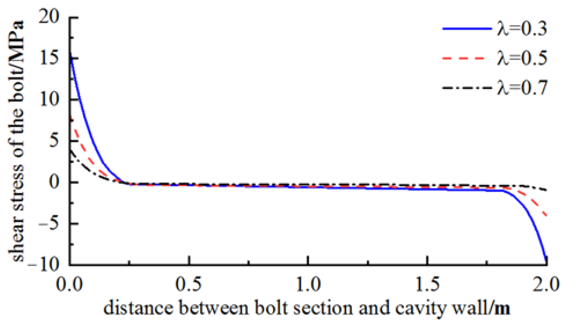
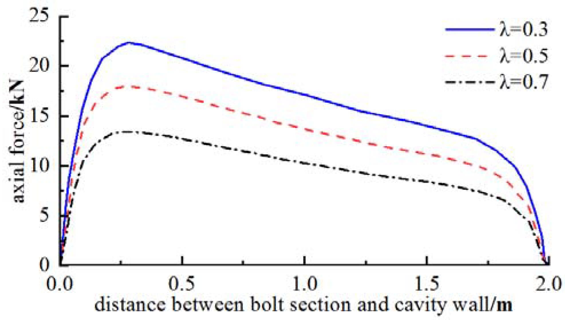
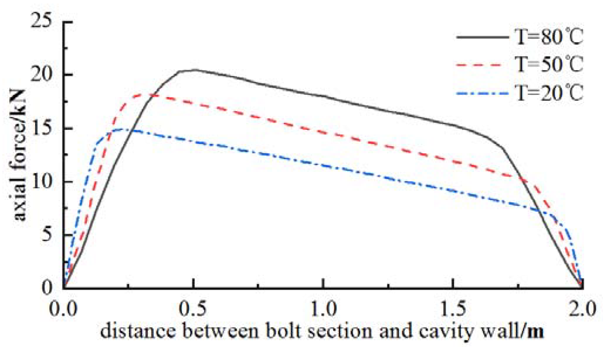
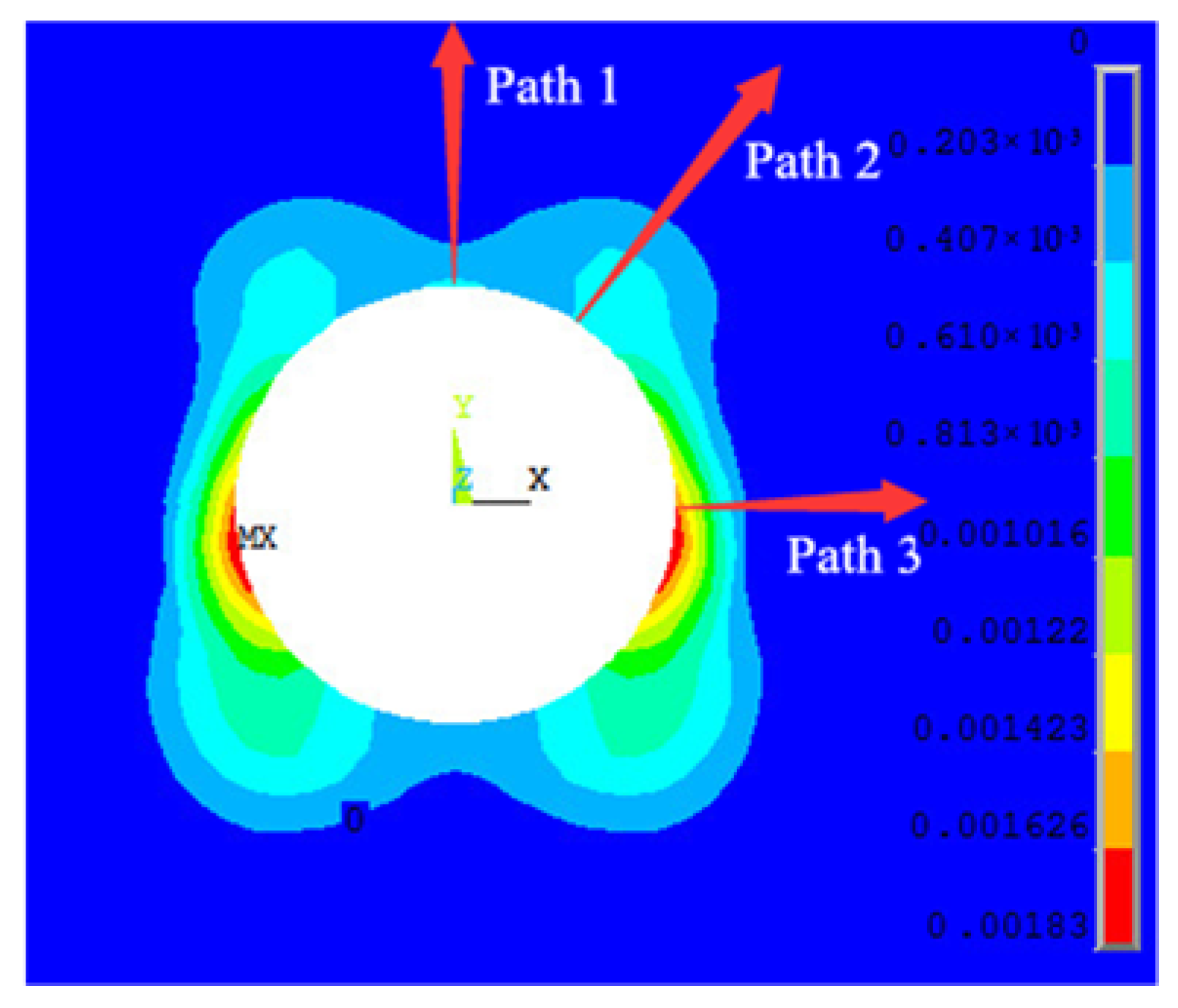
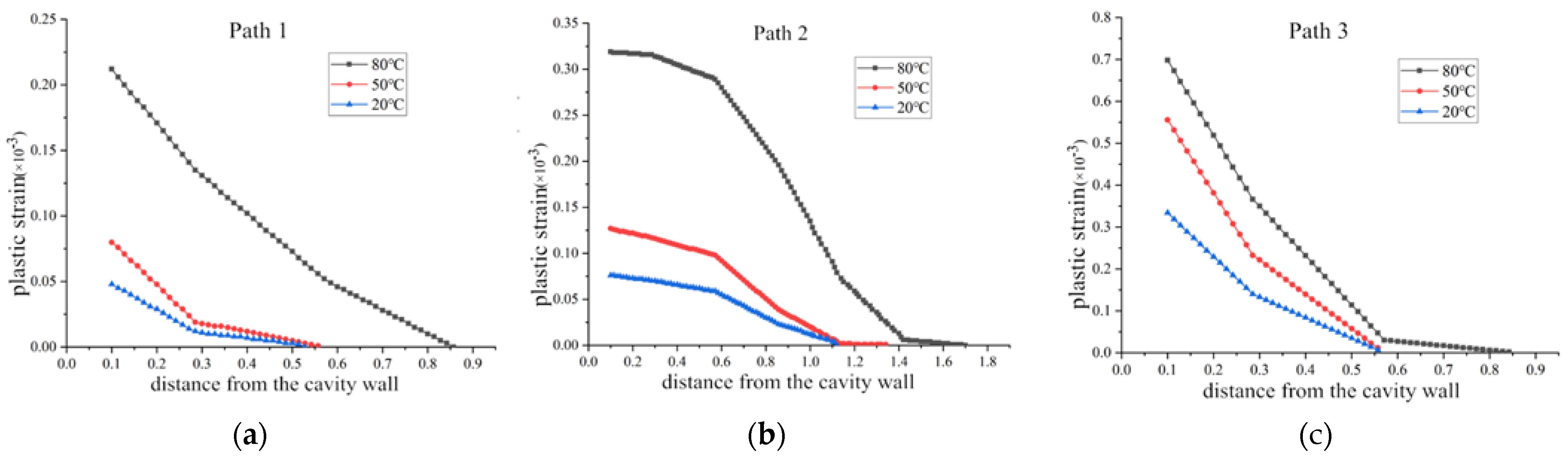
  • The axial force distribution and shear stress of the bolt along the bolt length under high ground temperatures were investigated.
The paper is structured as follows: Initially, drawing from existing research on fully grouted bolt theoretical models, the authors derive distribution functions for shear stress and axial force at the anchorage interface, incorporating the displacement of tunnel surrounding rock as a parameter. Subsequently, the impact of bolt–shotcrete support timing on the anchoring effect is thoroughly examined through the introduction of a displacement release rate. Next, the distribution of axial force and shear stress in bolts along their length under high ground temperature conditions is analyzed, accounting for the effects of temperature changes on the physical properties of the surrounding rock and anchorage system. Ultimately, the theoretical validity of the proposed model is corroborated through rigorous numerical simulation.

2. Analysis of Stress Distribution in Fully Grouted Bolts

This investigation focuses on a 4.1 km-long tunnel section with an elevated ground temperature within a hydraulic tunnel in Xinjiang. Constructed using drilling and blasting methods, the tunnel’s rock mass consists primarily of mica quartz schist interbedded with graphite schist. The tunnel remains dry, exhibiting no groundwater leakage. The overlying strata thickness is approximately 560 m, and longitudinal ventilation is employed to reduce the temperature within the tunnel.
As tunnels undergo excavation, stress redistribution prompts the surrounding rock to displace toward the tunnel. Following the installation of bolts within the surrounding rock, deformation is constrained by the bolts. Deformation is significant near the cavity wall and gradually decreases with increasing distance until reaching a point of no deformation. Consequently, after anchoring, shear stress pointing toward the cavity wall is transmitted to the bolt through the bonding material between the surrounding rock and the bolt at one end near the cavity wall. In contrast, at the other end far from the cavity wall, the bolt experiences shear stress directed away from the cavity wall. The bolt body is subject to opposing shear stresses, and a neutral point with zero shear stress emerges at a specific location along the bolt. The bolt segment extending from the cavity wall to the neutral point is referred to as the drawing segment, whereas the portion from the neutral point to the far end of the cavity wall is known as the anchorage segment, as depicted in Figure 1.

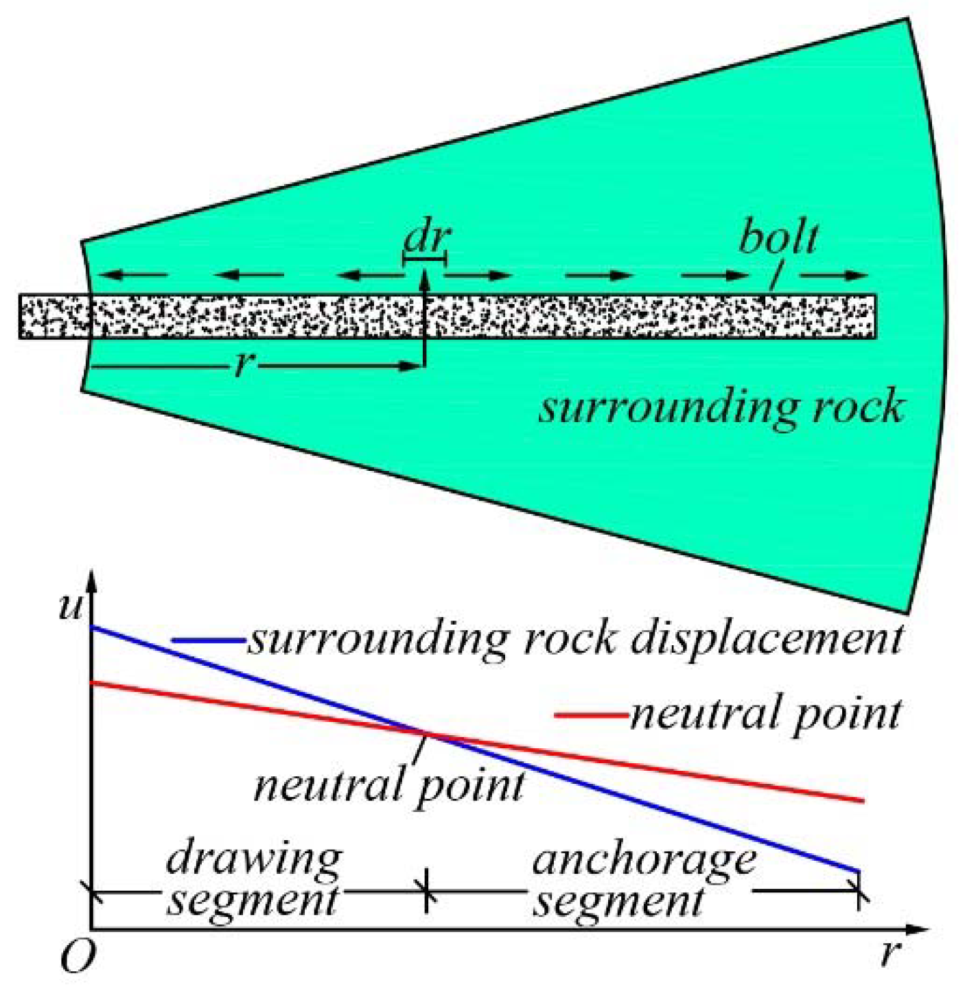
2.1. Basic Assumptions

In the construction sequence and process of fully grouted rock bolts, holes are drilled into the cavity wall following tunnel excavation. Bonding materials, such as mortar or resin anchoring agents, are then injected before steel bars are implanted. Upon solidification of the bonding material, a connection is formed between the bolt and the surrounding rock, resulting in an integrated anchorage-bearing system.
Theoretical analysis of this anchorage process and the force transmission characteristics of the system necessitates several assumptions:
(1)
The anchorage body, comprising the bolt and bonding material, remains elastic under external loads, and only experiences axial deformation in the bolt.
(2)
The bolt and bonding material maintain a complete bond without damage, such as slip failure or cracking. Moreover, the thinness of the bonding material justifies disregarding changes in shear stress on its inner and outer sides.

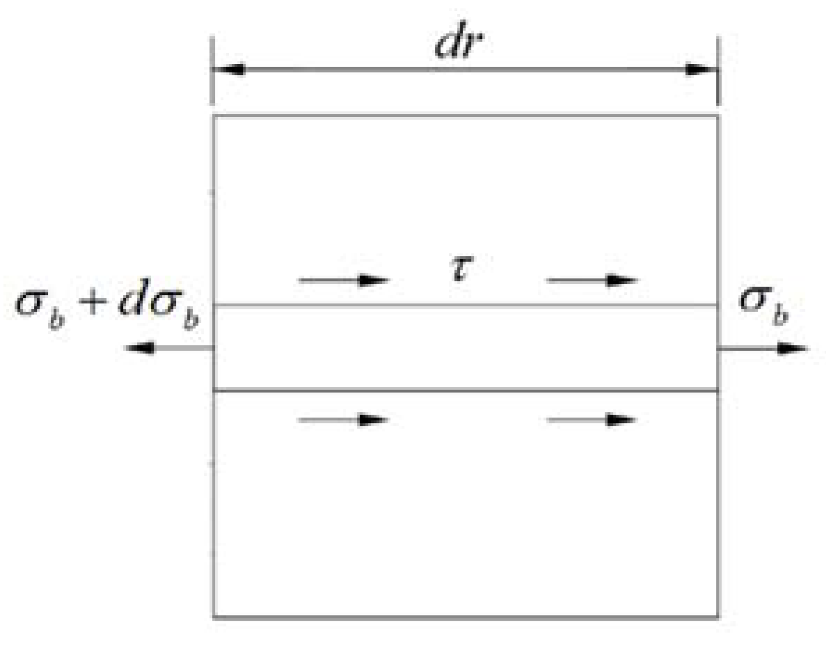
2.2. Stress Distribution of the Fully Grouted Bolt

Based on the above assumptions, an anchoring micro-element (dr), was obtained in order to study the interaction between the bolt and the surrounding rock, as shown in Figure 2.
The deformation caused by tunnel excavation generates deformation shear stress (τ) on the anchorage interface. By maintaining force balance, the following equation was derived:
d N ( r ) = A d σ b = π D τ d r
where N(r) is the axial force at the corresponding micro-element of the bolt, N; A is the cross-sectional area of the bolt, m2; D is the diameter of the bolt, m; and σb is the axial stress of the bolt, MPa.
Assuming that the axial displacement of the bolt is ub, directed towards the cavern, the axial stress distribution of the micro-element of the bolt can be expressed as:
σ b = E b ε b = E b d u b d r
where Eb is the elastic modulus of the bolt, and εb is the axial strain of the micro-element of the bolt.
Substituting Equation (1) into Equation (2) yields the following expression of displacement and interfacial shear stress of the bolt:
d 2 u b d r 2 = 4 E b D τ
Considering the assumption that the change in shear stress between the inner and outer sides of the bonding material is negligible, the shear stress in the anchorage layer of the bolt can be obtained as:
τ = G n h n ( u s u b )
where Gn is the shear modulus of the bonding material, GPa; hn is the thickness of the bonding material, m; and us is the radial displacement of the rock and soil surrounding the bolt after anchoring support.
Combining Equations (3) and (4), the differential equation of the axial displacement of the fully grouted bolt can be obtained as:
u b a 2 u b + a 2 u s = 0 ,   a 2 = 4 G n E b D h n
Upon solving the aforementioned differential equation, the following equation is obtained:
u b = C 1 e a r + C 2 e a r a e a r 2 e a r u s d r + a e a r 2 e a r u s d r
In order to derive the expression for the axial displacement of the bolt, it is essential to determine the radial displacement of the surrounding rock in the anchoring area. By substituting the expressions for the radial displacement of the surrounding rock in different zones, the axial displacement of the bolt can be calculated. Following tunnel excavation, the surrounding rock typically comprises plastic, elastic, and undisturbed zones, sequentially from the cavity wall. According to the Drucker–Prager criterion, the radius of the plastic zone post-tunnel excavation is given by [39]:
R p = r 0 [ ( P + k / 3 α ) ( 1 3 α ) P 1 + k / 3 α ] 1 3 α 6 α
where r0 is the tunnel excavation radius, m; P is the original rock stress, MPa; P1 is the support resistance, MPa; and k and α are the material constants related to the cohesion (c) of surrounding rock and the internal friction angle (φ), respectively [40].
k = 6 c cos φ 3 ( 3 + sin φ ) ,   α = 2 sin φ 3 ( 3 + sin φ )
The boundary displacement of the elastic and plastic zones of the tunnel under anchoring support is [41]:
u p = 3 α ( P + k / 3 α ) R p 2 G
Assuming that the volume of the surrounding rock in the plastic zone remains constant, the total displacement of the tunnel’s surrounding rock influenced by anchoring support is:
u 0 = R p u p r 0 = 3 α ( P + k / 3 α ) R p 2 2 G r 0
Taking into account the space effect and construction sequence of the tunnel, the displacement of the tunnel wall after anchoring and support is:
u 2 = u 0 u 1
where u1 is the released displacement of the surrounding rock before anchoring support, expressed by the displacement release rate λ, λ ∈ [0, 1]. Consequently, Equation (11) can be rewritten as:
u 2 = u 0 λ u 0 = ( 1 λ ) u 0
The support resistance of the shotcrete is [42]:
P 1 = k c u 2 ,   k c = 2 G c ( 2 r 0 h c h c 2 ) r 0 [ ( 2 2 ν c ) r 0 2 2 r 0 h c + h c 2 ]
where νc and Gc are the Poisson’s ratio and shear modulus of the shotcrete layer, respectively, and hc is the thickness of the shotcrete. After anchoring support, the radial displacement (us) of the surrounding rock in the anchoring area is:
u s = r 0 u 2 r
Substituting Equation (14) into Equation (6) yields the following equations:
u b = C 1 e a r + C 2 e a r a r 0 u 2 e a r 2 e a r r d r + a r 0 u 2 e a r 2 e a r r d r
d u b d r = C 1 a e a r C 2 a e a r a 2 r 0 u 2 e a r 2 e a r r d r a 2 r 0 u 2 e a r 2 e a r r d r
e a r r d r = ln | r | + i = 1 ( a r ) i i i !
When the independent variable (r) is large, the solutions provided by Equations (17) and (18) produce large errors. In this paper, through continuous integration by parts and subsequent series expansion, more accurate results can be obtained by considering the first finite term in the calculation.
e a r r d r = e a r a r e a r a r 2 d r e a r a r i = 0 ( 1 ) i i ! ( a r ) i
e a r r d r = e a r a r e a r a r 2 d r e a r a r i = 0 i ! ( a r ) i
According to engineering practice, the axial stress at both ends of the bolt is zero.
d u b d r | r = r 0 = 0 ,   d u b d r | r = r 0 + l = 0
By substituting Equation (21) into Equation (16), C1 and C2 can be obtained as follows:
C 1 = e a r 0 2 ( e 2 a l 1 ) [ i = 0 ( ( 1 ) i 1 ) i ! a i r 0 i + 1 e a r 0 i = 0 ( ( 1 ) i 1 ) i ! a i ( r 0 + l ) i + 1 ]
C 2 = e a ( r 0 + l ) 2 ( e 2 a l 1 ) [ e a r 0 i = 0 ( ( 1 ) i 1 ) i ! a i r 0 i + 1 i = 0 ( ( 1 ) i 1 ) i ! a i ( r 0 + l ) i + 1 ]
By substituting the constants C1 and C2 into Equations (1) and (4), the distribution functions of the axial force and shear stress of the fully grouted bolt at room temperature can be obtained as:
N ( r ) = a A E b [ C 1 e a r + C 2 e a r 1 2 i = 0 ( ( 1 ) i 1 ) i ! a i ( r ) i + 1 ]
τ ( r ) = G n h n [ C 1 e a r + C 2 e a r r 0 u 2 r + r 0 u 2 2 i = 0 ( ( 1 ) i + 1 ) i ! a i ( r ) i + 1 ]

2.3. Support Timing on Anchoring Effect and Bolt Stress

Determining the displacement release rate of the surrounding rock during different excavation steps in the numerical analysis of engineering excavation processes is a complex problem. It depends on factors such as the geological conditions, engineering excavation depth, supporting structure design, excavation method, supporting construction time, and auxiliary construction measures. A displacement release coefficient can be introduced to prevent unbalanced internal forces caused by excavation from being loaded onto an excavation step all at once. It is a simplified numerical analysis method that simulates unit changes sequentially across multiple construction phases. After tunnel excavation, the displacement generated when reaching secondary equilibrium without anchorage is called the total displacement (u) of the surrounding rock. Anchorage is applied before the surrounding rock reaches total displacement. To facilitate the analysis, the displacement release rate (λ) is introduced, and it represents the rate at which stored energy is released through displacement of materials.
Case 1: The tunnel had a radius (r0) of 1.5 m and an initial geostress (P0) of 6.49 MPa. The rock–soil body had an elastic modulus (Er) of 7.1 GPa, a Poisson’s ratio (νr) of 0.28, an internal friction angle (φ) of 37°, and cohesion (c) of 1.1 MPa. The shotcrete thickness (hc) was 0.15 m, and C20 concrete was used with an elastic modulus (Ec) of 12 GPa and a Poisson’s ratio (νc) of 0.167. The bolt had an elastic modulus (Eb) of 200 GPa, a diameter (D) of 250 mm, and a length (l) of 2 m, whereas the mortar anchoring layer had a thickness (hn) of 10 mm. When the displacement release rate was at values such as 0.3, 0.5, or 0.7, theoretical calculations for the plastic zone radius and shotcrete resistance are shown in Table 1, whereas the shear stress and axial force on bolts are shown in Figure 3 and Figure 4, respectively.
Under different displacement release rates, both positive and negative shear stress values occur at the anchorage body interface. The segment with positive values is known as the drawing segment, with shear stress pointing towards the cavity wall. In contrast, the segment with negative values is the anchoring segment, with shear stress pointing towards the deep part of the surrounding rock. At the neutral point, where shear stress is zero, the axial force of the bolt is at its maximum.
According to Table 1, Figure 3 and Figure 4, the plastic zone radius of the surrounding rock and the force borne by the anchoring structure vary with the timing of the bolt–shotcrete support. The study analyzed three different release rates, showing that when λ was 0.3, the axial force on the bolt and the shear stress on the interface between the bolt and surrounding rock were at their highest. At a distance of 0.28 m from the cavity wall, the maximum axial force on the bolt was 22.3 kN. The maximum shear stress at the cavity wall was 16.2 MPa, whereas the maximum shotcrete resistance was 3.24 MPa. The plastic zone had a radius of 3.09 m, the smallest observed in the study.
Conversely, when λ was 0.7, the axial force on the bolt and the shear stress on the interface between the bolt and surrounding rock were at their lowest. The maximum axial force was 13.1 kN, occurring at 0.25 m from the cavity wall, which was only 59% of that at λ = 0.3. The maximum shear stress was 4.5 MPa at the cavity wall. The shotcrete resistance was the lowest at 1.81 MPa, 44.1% less than that at λ = 0.3. The radius of the plastic zone at λ = 0.7 was the largest, measuring 3.53 m, 0.44 m more than that of λ = 0.3. These results suggest that a large displacement release rate diminishes the interaction between the bolt and the surrounding rock mass, leading to almost complete deformation of the surrounding rock. At this point, the bolt–shotcrete support becomes insignificant, and the surrounding rock bears greater deformation and load, making it more prone to loosening and damage. Choosing the appropriate time for bolt–shotcrete support after tunnel excavation ensures that the anchoring structure and surrounding rock form a common loading body. This can fully adjust and improve the surrounding rock’s stress state, limit the plastic zone’s expansion, and enhance the overall safety of the structure.

3. Effects of High Ground Temperature on the Mechanical Properties of Anchorage Systems

3.1. Introduction of the Thermal Deformation Equation of Material Parameters

The primary impact of high temperature on the anchoring system is the alteration of material mechanical properties in each component. Consequently, temperature changes generate thermal stress on both the surrounding rock and the bolt. The theoretical calculation primarily considers the temperature’s effect on the materials’ mechanical parameters. The current research summarizes the changing laws of mechanical properties of various materials with temperature through model tests and field monitoring. One reference fitted the empirical formula of the elastic modulus and Poisson’s ratio of the surrounding rock up to 200 °C using experimental data [43]:
E r T = ( 1 1.33 × 10 5 T 4.22 × 10 6 T 2 9.64 × 10 9 T 3 ) E r
ν r T = ( 0.0023 T + 0.94 ) ν r
where Er and νr denote the elastic modulus and Poisson’s ratio of surrounding rock at room temperature, and T is the temperature difference. As the temperature increases, the elastic modulus decreases gradually, whereas Poisson’s ratio decreases first and then increases.
Reference measures of the value of the elastic modulus of concrete with temperature changes were obtained, and the fitted relationship between 20 °C and 600 °C is expressed as [44]:
E c T = ( 0.982 0.0014 T ) E c
Reference studies of the mechanical properties of steel bars at high temperatures were utilized and gave the piecewise function of the elastic modulus of steel bars with changing temperature. The relationship within 370 °C can be expressed as [45]:
E b T = ( 1 4.86 × 10 4 T ) E b
By substituting the above relations into Equations (24) and (25), the distribution equations of axial force and shear stress of the bolt along the bolt length at high temperatures can be obtained as follows:
N T ( r ) = a A E b T [ C 1 e a r + C 2 e a r 1 2 i = 0 ( ( 1 ) i 1 ) i ! a i ( r ) i + 1 ]
τ T ( r ) = G n T h n [ C 1 e a r + C 2 e a r r 0 u 2 r + r 0 u 2 2 i = 0 ( ( 1 ) i + 1 ) i ! a i ( r ) i + 1 ]
In Case 1, the displacement release rate was set to λ = 0.5. The mechanical parameters at various temperatures were utilized for the theoretical calculations. Table 2 displays the theoretical calculation results of the plastic zone radius and the shotcrete’s support counterforce. Figure 5 and Figure 6 illustrate the theoretical calculation of the bolt’s shear stress and axial force, respectively.
According to Table 2, Figure 5 and Figure 6, the plastic zone radius of the surrounding rock enlarged, whereas the shotcrete resistance decreased with increasing temperature. This result indicates a decrease in the elastic modulus of the surrounding rock with increasing temperature. Specifically, the lower the elastic modulus, the weaker the rock, and the greater the deformation of the surrounding rock. Under such conditions, the surrounding rock bears more load, making it more susceptible to loosening and damage, resulting in a weaker anchoring effect of the shotcrete.
At a temperature of 20 °C, the shear stress of the anchorage body interface reached its highest value, peaking at 8.1 MPa, whereas the maximum axial force of the bolt was 17.9 kN, which occurred 0.28 m from the cavity wall. In contrast, at 80 °C, the shear stress reached its minimum, measuring only 3.4 MPa, which is only 42% of that at 20 °C. The bolt experienced a maximum axial force of 22.3 kN, 25% greater than the value at 20 °C, and the force occurred at a distance of 0.34 m from the cavity wall. As the temperature increases, the bonding ability between the bolt and the surrounding rock weakens. Consequently, the maximum shear stress value at the cavity wall decreases, the position of the neutral point moves away from the cavity wall, the length of the drawing segment increases, and the axial force of the bolt increases. Therefore, high-temperature environments require bolts with greater strength.

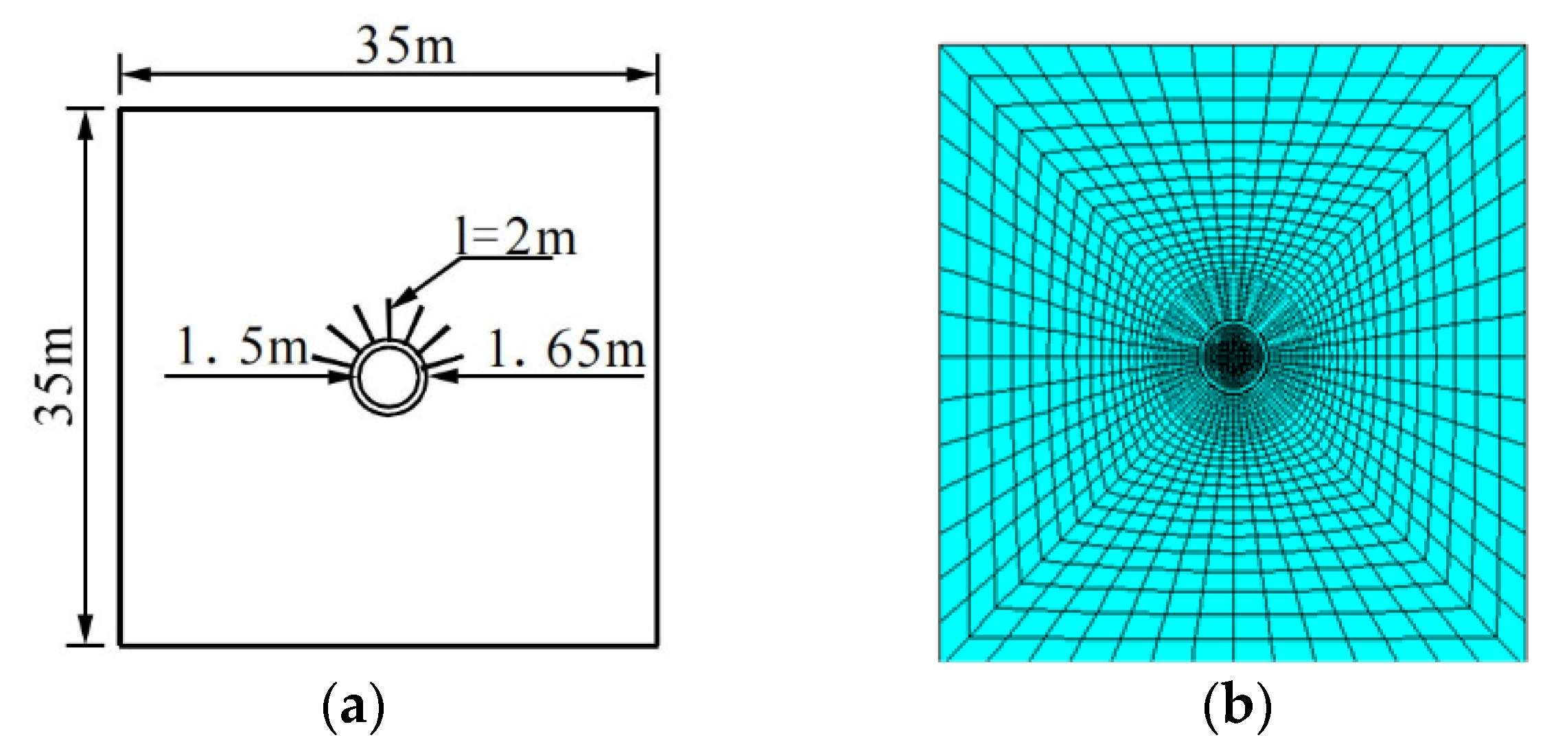
3.2. Model Validation

In order to validate the theoretical analysis, a comparative analysis was conducted using ANSYS numerical software. After tunnel excavation, the surrounding rock’s displacement and stress increased as it approached the cavern, and the influence range was three to five times the cavern diameter. Considering that the bolt will also disturb the surrounding rock during support, the calculation range was set to three times the length of the bolt plus the cavern diameter (35 m × 35 m). Displacement in the X direction constrained the model’s left and right boundaries, whereas displacement in the Y direction constrained the lower boundary. The surrounding rock adopted the elastic–plastic constitutive model and the D–P yield criterion, and the other material parameters remained the same as in Case 1.
Figure 7 illustrates the model and the finite element model’s geometrical dimensions. During meshing, the thermal simulation unit of the surrounding rock used plane55 and plane42 as structural calculation units, beam3 element for the shotcrete layer, and link1 element for the bolt. The bolt and surrounding rock had good bonding, and a common node model connected them. The simulation model divided a total of 3550 units. The indirect coupling method and the “element birth and death” technology simulated the excavation process during the calculation. The axial force of the bolt located at the top of the arch was analyzed, and its values were extracted at intervals of 0.25 m. Figure 8 displays the simulated bolt axial force value and the difference between the theory and simulation.
At simulated temperatures of 20 °C and 50 °C, the maximum axial force of the bolt occurred at 0.25 m, with values of 17.74 kN and 14.47 kN, respectively. When the temperature reached 80 °C, the maximum axial force was 20.09 kN, occurring at 0.5 m. As the simulated temperature increased, the drawing segment of the bolt lengthened, and the neutral point moved away from the cavity wall, which is consistent with the results obtained from the theoretical analysis. These findings validate the computational model’s accuracy in this paper. Furthermore, the simulated axial force values of the bolt align with the theoretical values, with a maximum difference of 7.7%, which is within an acceptable range. The difference between the two values may be due to the fact that the theoretical analysis only considered the effect of temperature change on the physical properties of the surrounding rock and anchoring structure. Conversely, the numerical simulation accounts for the impact of temperature stress caused by temperature change. However, temperature stress minimized the bolt’s stress at normal and low temperatures, but significantly impacted the stress at high temperatures. Additionally, temperature stress is a secondary influencing factor under different temperature conditions. Figure 9 displays the plastic strain paths, whereas Figure 10 illustrates the plastic strain variation in different paths.
Based on Figure 10, the plastic strain at a particular location increases as the temperature of the surrounding rock increases, leading to a larger plastic zone. Additionally, the plastic strain is inversely proportional to the distance from the cavity wall. The plastic strain growth and changes in the plastic zone on Path 1 and Path 2 were significantly higher within a temperature range of 50 °C to 80 °C than within a temperature range of 20 °C to 50 °C. This suggests that the plastic zone at the vault and spinner is more sensitive to temperature changes at medium to high temperatures than at normal and low temperatures. The plastic strain variation with temperature on Path 3 indicates that the plastic strain at the arch waist increases proportionally with an increase in temperature, implying a certain regularity in the growth of the plastic strain at the arch waist. Further information can be found in Figure 9. The simulation results are consistent with the theoretical analysis, demonstrating the computational model’s accuracy. However, the theoretical and simulated values differ due to the theoretical analysis only considering the effect of temperature change on the physical properties of the surrounding rock and anchoring structure. In contrast, the numerical simulation also considers the effect of temperature stress caused by temperature change.

4. Conclusions

In this study, the investigation focused on the distribution of shear stress and axial force on fully grouted rock bolts at the anchorage interface, which was attributed to deformation of the surrounding rock. The primary parameter considered in this research was the displacement of the tunnel’s surrounding rock. Furthermore, the study explored the effects of the displacement release rate on the anchorage efficacy of bolt–shotcrete support timing, along with the impact of temperature variations on the physical properties of the surrounding rock and anchorage system. This was achieved by analyzing the axial force and shear stress distribution along the bolt length under elevated ground temperatures. The theoretical findings were substantiated by numerical simulations. The key conclusions drawn from this study include:
1.
Lower displacement release rates result in more effective bolt–shotcrete support. With reduced displacement release rates, bolt–shotcrete support can fully adapt and improve the stress state of the surrounding rock, restricting plastic zone expansion in the surrounding rock and ensuring comprehensive structural stability.
2.
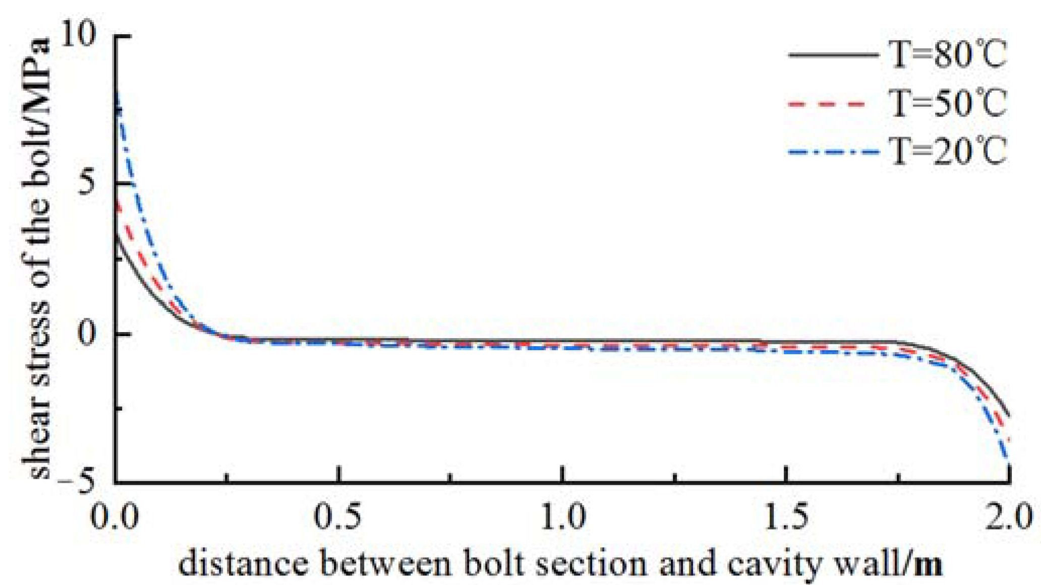
In high-temperature environments, the bond strength between bolts and rock mass weakens as the temperature of the surrounding rock increases. This results in small interfacial shear stress and greater maximum axial force on bolts. At 80 °C, the maximum axial force increased by 25% compared to normal temperatures, and the neutral point moved away from the cavity wall.
3.
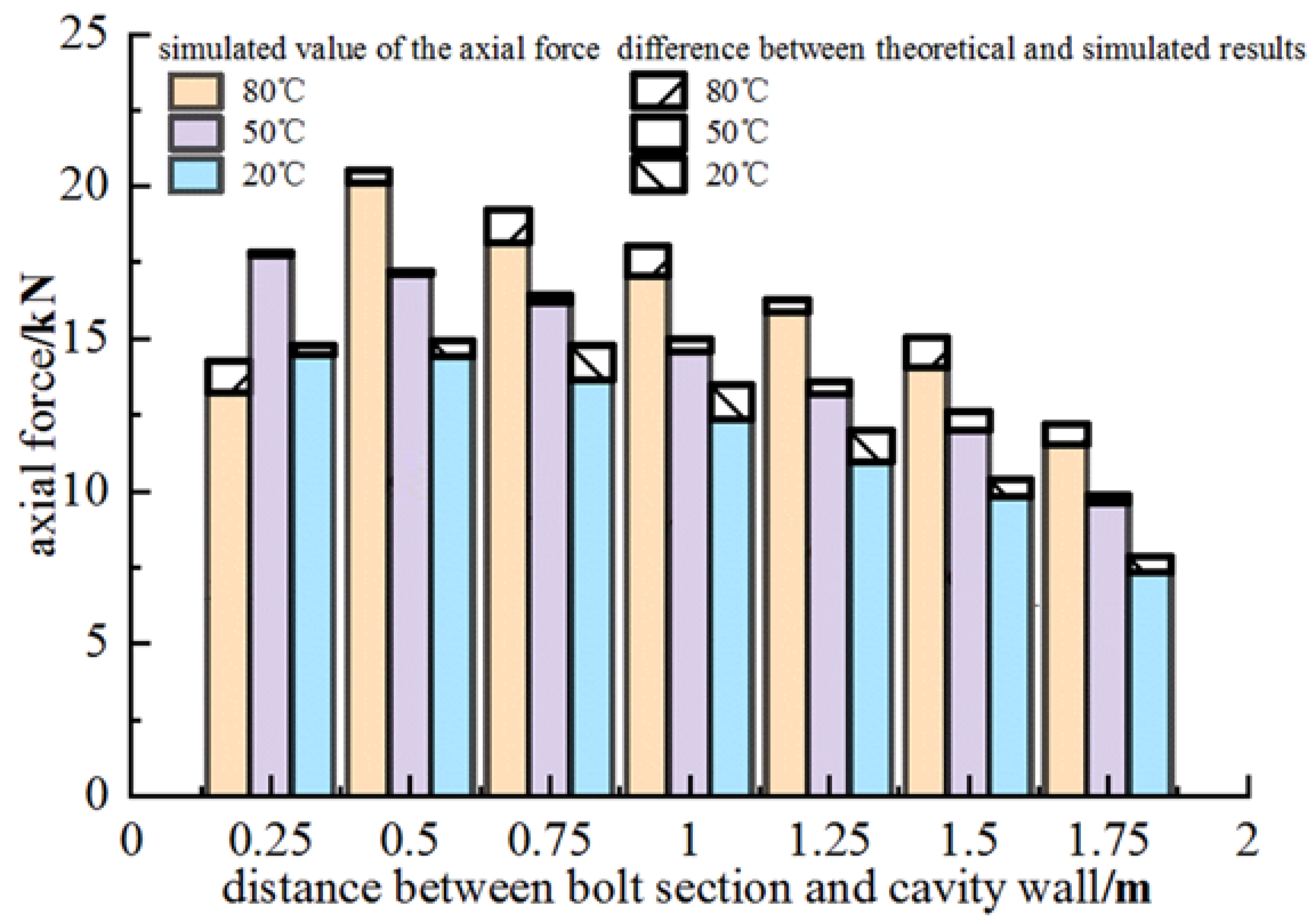
The proposed theoretical model was validated through numerical simulations, which demonstrated that temperature fluctuations primarily affect the distribution of bolt axial force by impacting the anchoring system’s pertinent material parameters. Additionally, temperature stress exerts a more significant influence on bolt stress at elevated temperatures than at normal temperatures.
4.
This study establishes a mechanical model of fully grouted bolts in tunnels under high geothermal conditions, investigates the mechanical properties of fully grouted bolts in hydraulic tunnels under such environments, derives the distribution function of stress and interfacial shear stress of bolts, and verifies theoretical soundness using numerical calculations. However, a notable gap remains between computational analysis models and real-world engineering scenarios. To bridge this gap, the development of a more precise and dependable theoretical model is essential.
Although this paper primarily addresses deep, high-geothermal hydraulic tunnel engineering, the findings can also be applied to other underground projects facing high-geothermal challenges, such as high-temperature tunnels and deep geothermal mining. The research outcomes hold significance for analogous engineering endeavors. Future research should focus on refining the theoretical model presented in this study in order to better capture the intricate relationships between temperature, displacement, and the material properties in anchorage systems. This can be achieved through the development of advanced numerical simulations, model validation via experimental investigations, and the exploration of novel methodologies for optimizing the design and functionality of anchoring systems in geotechnical engineering. Expanding upon the conclusions of this study, additional research directions can be identified to further advance understandings of the mechanical behavior of fully grouted rock bolts under diverse conditions. To complement the theoretical and numerical analyses, it would be beneficial to conduct experimental studies on fully grouted rock bolts within controlled environments. This would aid in verifying the accuracy and reliability of the established models. Such investigations should concentrate on recreating various ground temperature and displacement scenarios and evaluating the performance of different rock bolt materials and designs.

Author Contributions

H.J. and S.L.: conceptualization, methodology, software, and validation; S.L., Q.L. and J.X.: formal analysis, investigation, data curation, and writing—original draft preparation; J.X. and H.J.: conceptualization, writing—review and editing, visualization, and funding acquisition. All authors have read and agreed to the published version of the manuscript.

Funding

This work was financially supported by the National Natural Science Foundation of China (Grant No. 51769031, 52179130) and the Regional Innovation Guidance Plan project of the XPCC (Grant No. 2021BB004).

Institutional Review Board Statement

Not applicable.

Informed Consent Statement

Not applicable.

Data Availability Statement

The data presented in this study are available on request from the corresponding author.

Acknowledgments

We are grateful to two anonymous reviewers for their constructive comments.

Conflicts of Interest

The authors declare no conflict of interest. The funders had no role in the design of the study; in the collection, analyses, or interpretation of data; in the writing of the manuscript; or in the decision to publish the results.

References

  1. Yu, Y.; Chen, B.; Wang, F.; Wang, J.; Ke, D. Zonal disintegration of surrounding rock in deep underground cave based on force analysis of rock bolts. Chin. J. Rock Mech. Eng. 2017, 37, 1629–1640. [Google Scholar] [CrossRef]
  2. Wang, H.; Li, Y.; Ni, Q.; Utili, S.; Jiang, M.; Liu, F. Analytical solutions for the construction of deeply buried circular tunnels with two liners in rheological rock. Rock Mech. Rock Eng. 2013, 46, 1481–1498. [Google Scholar] [CrossRef]
  3. Xu, J.; Ren, Q.; Shen, Z. Sensitivity analysis of the influencing factors of slope stability based on LS-SVM. Geomech. Eng. 2017, 13, 447–458. [Google Scholar] [CrossRef]
  4. Sakhno, I.; Liashok, I.; Svitlana, S.; Oleksandr, I. Method for controlling the floor heave in mine roadways of underground coal mines. Min. Miner. Depos. 2022, 16, 1–10. [Google Scholar] [CrossRef]
  5. Sakhno, I.; Isayenkov, O.; Rodzin, S. Local reinforcing of footing supported in the destroyed rock massif. Min. Miner. Depos. 2017, 11, 9–16. [Google Scholar] [CrossRef]
  6. Cao, G.; Liu, H. Complex Geological Conditions and Detection Technology of Tunnel. In Three-Dimensional Exploration Technology of Tunnel Geology; Springer: Berlin/Heidelberg, Germany, 2022; pp. 11–28. [Google Scholar]
  7. Jiang, H.; Sun, H.; Shi, K.; Xu, J. Stability Analysis of the Surrounding Rock-Lining Structure in Deep-Buried Hydraulic Tunnels Having Seepage Effect. Sustainability 2022, 14, 16586. [Google Scholar] [CrossRef]
  8. Xu, D.; Zhang, B.; Zubin, A.; Bu, X.; Pan, H.; Chen, S. Spatial-temporal evolution principle of temperature field in a high-temperature geothermal highway tunnel. Ain Shams Eng. J. 2023, 14, 101965. [Google Scholar] [CrossRef]
  9. Kang, F.; Li, Y.; Tang, C.; Li, T.; Wang, K. Numerical Study on Thermal Damage Behavior and Heat Insulation Protection in a High-Temperature Tunnel. Appl. Sci. 2021, 11, 7010. [Google Scholar] [CrossRef]
  10. Lee, Y.-K.; Pietruszczak, S. A new numerical procedure for elasto-plastic analysis of a circular opening excavated in a strain-softening rock mass. Tunn. Undergr. Space Technol. 2007, 23, 588–599. [Google Scholar] [CrossRef]
  11. Borgia, A.; Oldenburg, C.M.; Zhang, R.; Pan, L.; Daley, T.M.; Finsterle, S.; Ramakrishnan, T. Simulations of CO2 injection into fractures and faults for improving their geophysical characterization at EGS sites. Geothermics 2017, 69, 189–201. [Google Scholar] [CrossRef]
  12. Yan, J.; He, C.; Wang, B.; Meng, W. Influence of high geotemperature on rockburst occurrence in tunnel. Rock Soil Mech. 2017, 40, 1543–1550. [Google Scholar] [CrossRef]
  13. Gudala, M.; Govindarajan, S.K.; Yan, B.; Sun, S. Numerical investigations of the PUGA geothermal reservoir with multistage hydraulic fractures and well patterns using fully coupled thermo-hydro-geomechanical modeling. Energy 2022, 253, 124173. [Google Scholar] [CrossRef]
  14. Barla, G.; Bonini, M.; Semeraro, M. Performance monitoring and analysis of a yield-control support system in squeezing rock. In Rock Mechanics in Civil and Environmental Engineering; CRC Press: Boca Raton, FL, USA, 2010. [Google Scholar] [CrossRef]
  15. Moritz, B. Yielding elements—Requirements, overview and comparison/Stauchelemente—Anforderungen, berblick und Vergleich. Geomech. Tunn. 2011, 4, 221–236. [Google Scholar] [CrossRef]
  16. Li, C.C.; Doucet, C. Performance of D-Bolts Under Dynamic Loading. Rock Mech. Rock Eng. 2012, 45, 193–204. [Google Scholar] [CrossRef]
  17. Krykovskyi, O.; Krykovska, V.; Skipochka, S. Interaction of rock-bolt supports while weak rock reinforcing by means of injection rock bolts. Min. Miner. Depos. 2021, 15, 8–14. [Google Scholar] [CrossRef]
  18. Liu, Y.; Xia, C.; Wu, F.; Xu, C.; Deng, Y. A combined support technology of long and short bolts of soft rock tunnels under high ground stresses. Chin. J. Rock Mech. Eng. 2019, 39, 105–114. [Google Scholar] [CrossRef]
  19. Freeman, T.J. Behavior of Fully Bonded Rock Bolts in the Kielder Experimental Tunnel. Tunn. Tunn. 1978, 10, 37–40. [Google Scholar] [CrossRef]
  20. Wang, M.; He, X.; Zhang, Y. Mechanical model of full-length anchored bolt and its application. Met. Mine 1983, 4, 24–29. [Google Scholar]
  21. Li, C. Study on the loading and deformation of tunnel segments in soft clay with consideration for the soil mass rheological characteristics. Geotech. Geol. Eng. 2018, 37, 673–682. [Google Scholar] [CrossRef]
  22. Kargar, A.R. An analytical solution for circular tunnels excavated in rock masses exhibiting viscous elastic-plastic behavior. Int. J. Rock Mech. Min. Sci. 2019, 124, 104128. [Google Scholar] [CrossRef]
  23. Wu, F.; Wang, Z.; Xia, C.; Deng, Y.; Liu, Y. Analytical design method for yielding pipe length of yielding bolt. Tunn. Constr. 2019, 39, 119–124. [Google Scholar] [CrossRef]
  24. Tao, L.; Hongbin, C.; Yonggang, W.; Jian, Z.; Minnian, Z. Analysis on the influence of the lateral pressure coefficient on the bolt in the tunnel system with high ground stress. Chin. J. Undergr. Space Eng. 2020, 16, 437–441. [Google Scholar]
  25. Zhao, L. Study on stress distribution and influencing factors of grouting anchor in tunnel surrounding rock. J. Hebei Univ. Eng. 2021, 38, 63–68. [Google Scholar] [CrossRef]
  26. Li, P.; Huang, J.; Chen, K.; Tong, L. Statistical analysis on temporal and spatial characteristics of the axial force of anchor bolts in tunneling. Mod. Tunn. Technol. 2021, 58, 227–236. [Google Scholar] [CrossRef]
  27. Wen, J.; Zhang, Y.; Wang, C. Study of mechanical model of fully grouted rock bolt’s anchorage interface in tunnel surrounding rock. Rock Soil Mech. 2022, 34, 1645–1651. [Google Scholar] [CrossRef]
  28. Hao, Z.; Ming, X.; Chen, J. Study of anchoring mechanism and analysis of anchoring effect of fully grouted rock anchor in large-scale underground caverns. Rock Soil Mech. 2016, 37, 1503–1511. [Google Scholar]
  29. Liu, G.; Xiao, M.; Chen, J.; Zhou, H. Stress analysis method of fully grouted rock bolt in underground caverns. J. Huazhong Univ. Sci. Technol. 2017, 45, 113–116. [Google Scholar] [CrossRef]
  30. Liu, C.; Li, Y. Research progress in bolting mechanism and theories of fully grouted bolts in jointed rock masses. Chin. J. Rock Mech. Eng. 2018, 37, 1856–1872. [Google Scholar] [CrossRef]
  31. Yuan, Y.-H.; Xiao, M.; Chen, J.-T. A method for simulating stress distribution along fully grouted anchor. Rock Soil Mech. 2018, 39, 1908. [Google Scholar] [CrossRef]
  32. Zhao, B.; Jin, J.; Wang, G.; Minghua, H.; Xin, T. Nonlinear Analysis on Mechanical Behavior of Fully Grouted Bolt in Tunnels. Met. Mine 2022, 51, 85. [Google Scholar] [CrossRef]
  33. Zhang, Y.; Zhuang, X. Cracking elements method for dynamic brittle fracture. Theor. Appl. Fract. Mech. 2019, 102, 1–9. [Google Scholar] [CrossRef]
  34. Zhang, Y.; Mang, H.A. Global cracking elements: A novel tool for Galerkin-based approaches simulating quasi-brittle fracture. Int. J. Numer. Methods Eng. 2020, 121, 2462–2480. [Google Scholar] [CrossRef]
  35. Zhang, Y.; Huang, J.; Yuan, Y.; Mang, H.A. Cracking elements method with a dissipation-based arc-length approach. Finite Elem. Anal. Des. 2021, 195, 103573. [Google Scholar] [CrossRef]
  36. Owaid, K.; Hamdoon, A.; Matti, R.; Saleh, M.; Abdelzaher, M. Waste Polymer and Lubricating Oil Used as Asphalt Rheological Modifiers. Materials 2022, 15, 3744. [Google Scholar] [CrossRef]
  37. Abdelzaher, M.A.; Farahat, E.M.; Abdel-Ghafar, H.M.; Balboul, B.A.A.; Awad, M.M. Environmental Policy to Develop a Conceptual Design for the Water–Energy–Food Nexus: A Case Study in Wadi-Dara on the Red Sea Coast, Egypt. Water 2023, 15, 780. [Google Scholar] [CrossRef]
  38. Benjeddou, O.; Ravindran, G.; Abdelzaher, M.A. Thermal and Acoustic Features of Lightweight Concrete Based on Marble Wastes and Expanded Perlite Aggregate. Buildings 2023, 13, 992. [Google Scholar] [CrossRef]
  39. Sun, Z.-P.; Gao, Z.-N.; Meng, X.-R. Permeability Coefficient of Damage Zone of Surrounding Rock Based on Drucker-Prager Criterion. J. Yangtze River Sci. Res. Inst. 2013, 30, 26. [Google Scholar] [CrossRef]
  40. Peng, C.; Bohou, X. Matching method of DP yield criterions to MC based on value of internal frictional angle. Chin. Q. Mech. 2012, 33, 269–274. [Google Scholar] [CrossRef]
  41. Kun, W.; Guangmin, Z.; Xiangrui, M. The plastic analaysis of surrounding rock of roadway based on Drucker-Prager yield criterions of MC yield criterion. Safe Coal Mines 2013, 44, 67–70. [Google Scholar] [CrossRef]
  42. Fu, C.; Zhou, H.; Chen, S. Equivalent mechanical model of joined rockmass reinforced by shotcrete lining and its application. Rock Soil Mech. 2009, 30, 1967–1973. [Google Scholar] [CrossRef]
  43. Zhang, G. Analysis of bonding mechanism of wholly grouted anchor under high ground temperature environment. Master’s Thesis, Southwest Jiaotong University, Chengdu, China, 2018. [Google Scholar]
  44. Qin, L.; Song, Y.; Wang, Y.; Zhang, Z.; Yu, C. Testing research of mechanics characteristics of concrete affected by high temperature. Concrete 2004, 5, 9–11. [Google Scholar]
  45. Ma, Y. Thermal and Mechanical Properties of Steel and Concrete under High Temperature. Sci. Technol. West China 2011, 10, 37–39. [Google Scholar] [CrossRef]
Figure 1. The force and displacement of the bolt in the rock mass.
Buildings 13 01280 g001
Figure 2. Anchoring micro-element.
Buildings 13 01280 g002
Figure 3. Curves of shear stress distribution at different displacement release rates (λ).
Buildings 13 01280 g003
Figure 4. Axial force distribution at different release rates (λ).
Buildings 13 01280 g004
Figure 5. Curves of Shear Stress Distribution at Different Temperatures.
Buildings 13 01280 g005
Figure 6. Curves of axial force distribution at different temperatures.
Buildings 13 01280 g006
Figure 7. Simulation model: (a) geometric model; (b) finite element model.
Buildings 13 01280 g007
Figure 8. The simulated value of the axial force of the bolt.
Buildings 13 01280 g008
Figure 9. Paths of plastic strain in the plotting contour.
Buildings 13 01280 g009
Figure 10. Variations in plastic strain along different paths: (a) Path 1; (b) Path 2; (c) Path 3.
Buildings 13 01280 g010
Table 1. Plastic zone radius and shotcrete resistance at displacement release rates of 0.3, 0.5, and 0.7.
Displacement Release Rate λPlastic Zone Radius/mShotcrete Resistance/MPa
0.33.093.24
0.53.262.60
0.73.531.81
Table 2. Theoretical values of plastic zone radius and shotcrete resistance at 20 °C, 50 °C, and 80 °C.
Temperature/°CPlastic Zone Radius/mShotcrete Resistance/MPa
203.262.60
503.292.54
803.302.51
Disclaimer/Publisher’s Note: The statements, opinions and data contained in all publications are solely those of the individual author(s) and contributor(s) and not of MDPI and/or the editor(s). MDPI and/or the editor(s) disclaim responsibility for any injury to people or property resulting from any ideas, methods, instructions or products referred to in the content.

