Review

An Overview of the Application of Fiber-Reinforced Cementitious Composites in Spray Repair of Drainage Pipes

1
China Three Gorges Corporation, Wuhan 430010, China
2
Yangtze Ecology and Environment Co., Ltd., Wuhan 430077, China
*
Author to whom correspondence should be addressed.
Buildings 2023, 13(5), 1119; https://doi.org/10.3390/buildings13051119
Submission received: 14 March 2023 / Revised: 9 April 2023 / Accepted: 19 April 2023 / Published: 23 April 2023

Abstract

:
The structural performance of buried drainage pipes is gradually deteriorating under the influence of external loads and chemical and microbial corrosion. It is crucial to reinforce them and improve their bearing capacity for safe use. One of the important technologies used to extend the service life of deteriorated pipes is the use of fiber-reinforced cementitious composites (FRCC) for spray repair. Combined with the current situation of drainage pipes, this article introduces the basic properties of FRCC, briefly describes the requirements for material performance for drainage pipe spraying rehabilitation, reviews the structural bearing capacity of drainage pipes repaired by spraying with FRCC, and discusses the relevant research and engineering applications of the spraying method. Studies show that FRCC has high strength and corrosion resistance, and excellent sprayability. The structural performance of the host pipe is significantly improved after repair, but measures should be taken to enhance the interfacial bonding performance during the repair. In the design of the liner wall thickness, there is no unified calculation theory, and the existing methods have not considered the influence of secondary load on the structure. It is recommended to combine the type of pipe defects and the degree of deterioration in further study.

1. Introduction

Drainage pipes are an important part of urban underground buildings and city infrastructure. By the end of 2021, the total length of urban drainage pipes in China reached 872,000 km, and the proportion of drainage pipes more than 10 years old was more than 40% (Figure 1). For example, most of the concrete drainage pipes in Beijing, Guangzhou, Shanghai, and other cities are over 30 years old. European and North American countries are faced a large number of aging municipal pipes that are in urgent need of maintenance and renewal. For the problem of aging buried pipes, a variety of trenchless rehabilitation techniques have been proposed, such as cured-in-place pipe, slip lining, spray lining, etc. [1,2,3,4,5]. In recent years, the majority of urban drainage pipes in China have started facing similar problems, with frequent leakage, corrosion, rupture, and even collapse, which adversely affect the safe operation of municipal pipelines and public safety [6,7,8]. Many cities have started on the renewal of old pipe networks; the investment costs of government departments in pipe network renovation and reinforcement have been rising year by year, and related safety issues around municipal pipe networks are a major consideration for future urban construction in China [9].
Trenchless rehabilitation and renewal technology has gained widespread usage in the rehabilitation of drainage pipes because of its economical and environmentally friendly nature [10,11]. Of these technologies, lining with sprayed cementitious materials is prevalent for the rehabilitation of various drainage pipes and culverts due to its flexible construction, rapid repair speed, superior structural performance, and resistance to corrosion. Lining with sprayed cementitious materials method is a rehabilitation method in which a fiber-reinforced cementitious composite for repair is uniformly coated on the inner surface of the host pipe to form a lined pipe by centrifugal or pressure spraying, as shown in Figure 2. This technology is more widely used in Europe and North American countries; in recent years, China has also started to use this technology for the spraying repair of drainage pipes, and has achieved better repair results [12,13,14,15]. At present, the main research related to spraying methods of cementitious materials concerns the development of new fiber-reinforced cementitious composites, and the study of the structural bearing capacity of the repaired structure [14,16,17,18,19].
Since the introduction of ultra-high-performance concrete, there has been a continuous pursuit of high-performance materials with long service life, high strength, and corrosion resistance. Based on traditional mortar and concrete, millimeter- and micron-sized aggregates are added to improve the compressive and flexural capacity of the material [18,19,20,21]. Fiber-reinforced cementitious composites (FRCC) are composite materials with fibers as reinforcing materials and mortar as bonding matrix. The tensile, flexural, cracking, fatigue, vibration, and impact resistance of the material are significantly improved by the addition of fibers. When cementitious materials are used for spraying repair and reinforcement of old pipes, it is required that the repaired pipes can restore or exceed the structural strength of the original pipes, and the lining layer can bear some or all of the external loads alone. The lined pipe mainly fails due to tensile damage and debonding from the interface with the original pipe, so the lining material needs to have good toughness and bonding properties, and deform in concert with the original pipe when subjected to external loads and jointly stressed [14,22]. According to the test results of the bearing performance of the repaired pipe, the corrosion resistance, uniform spraying performance, and interfacial bonding performance of the lining material with the original pipe have a greater impact on the repair effect [14,16,17]. In concrete structure repair and reinforcement, some scholars also proposed the compatibility of repair materials and base concrete, such as volume deformation compatibility, mechanical property compatibility (the compressive, tensile, and flexural strength should be higher than that of base concrete), interfacial bonding compatibility, and permeability compatibility, which provide some guidelines for structural repair and reinforcement design [23,24,25,26].
The fiber-reinforced cementitious composite material used in the spraying method is usually a finished dry-mixed mortar material, which can be used only by adding water according to a certain ratio when repairing on site. The main ingredients are high-grade silicate cement, well-graded quartz sand, microsilica powder, reinforcing fiber, a water-reducing agent, a quick-setting agent, etc. In terms of the composition and construction requirements, there is a clear difference from ordinary high-performance or ultra-high-performance concrete: in the absence of coarse aggregates, its performance index can exceed that of some high-performance concrete. For example, high-performance fiber-reinforced cementitious composite materials such as MS-10000 and PL-8000, developed by AP/M, have the characteristics of high strength, durability, and corrosion resistance after adding polypropylene short fibers, with a compressive strength up to 70 MPa and tensile strength around 4.5–5.5 MPa, and so are also widely used in some domestic projects. Some domestic manufacturers have also developed similar special repair mortars, such as the H-70 fiber-reinforced cementitious composite material developed by Wuhan CUG Trenchless Technology Research Institute. The material performance parameters have reached a good level, as shown in Table 1 [14,15,21].
With the improvement of the understanding of the structural properties between the lining material and the original pipe, higher requirements for fiber-reinforced cementitious composites have been put forward in terms of mechanical properties, such as the toughness, tensile strength, self-healing properties, and cracking resistance of the material and the bonding performance of the original pipe [14,23,27]. The further development and application of cementitious composites spray construction of trenchless repair technology will be carried out mainly in terms of new lining materials, structural load-bearing performance enhancement, and other related research. In this paper, based on the types of defects and usage environment of drainage pipelines in China, the demand for fiber-reinforced cementitious composites by the spraying method is analyzed, and the research progress and structural performance testing of fiber-reinforced cementitious composites after repair are reviewed. The current research status of lining wall thickness design is discussed, and future research needs are pointed out, providing a reference for the development of new cementitious composite lining materials and the application of cementitious material spraying repair technology for trenchless repair.

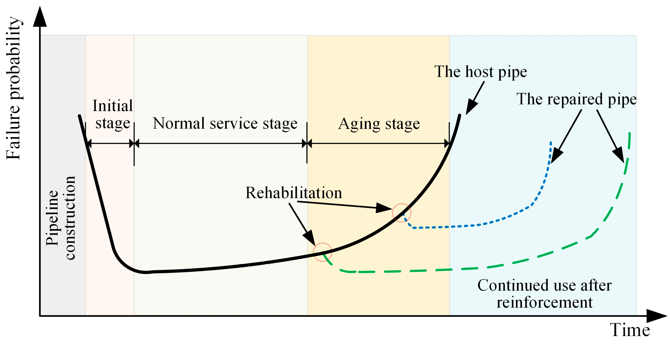
2. Survey of Drainage Pipe Defects and Repair Requirements

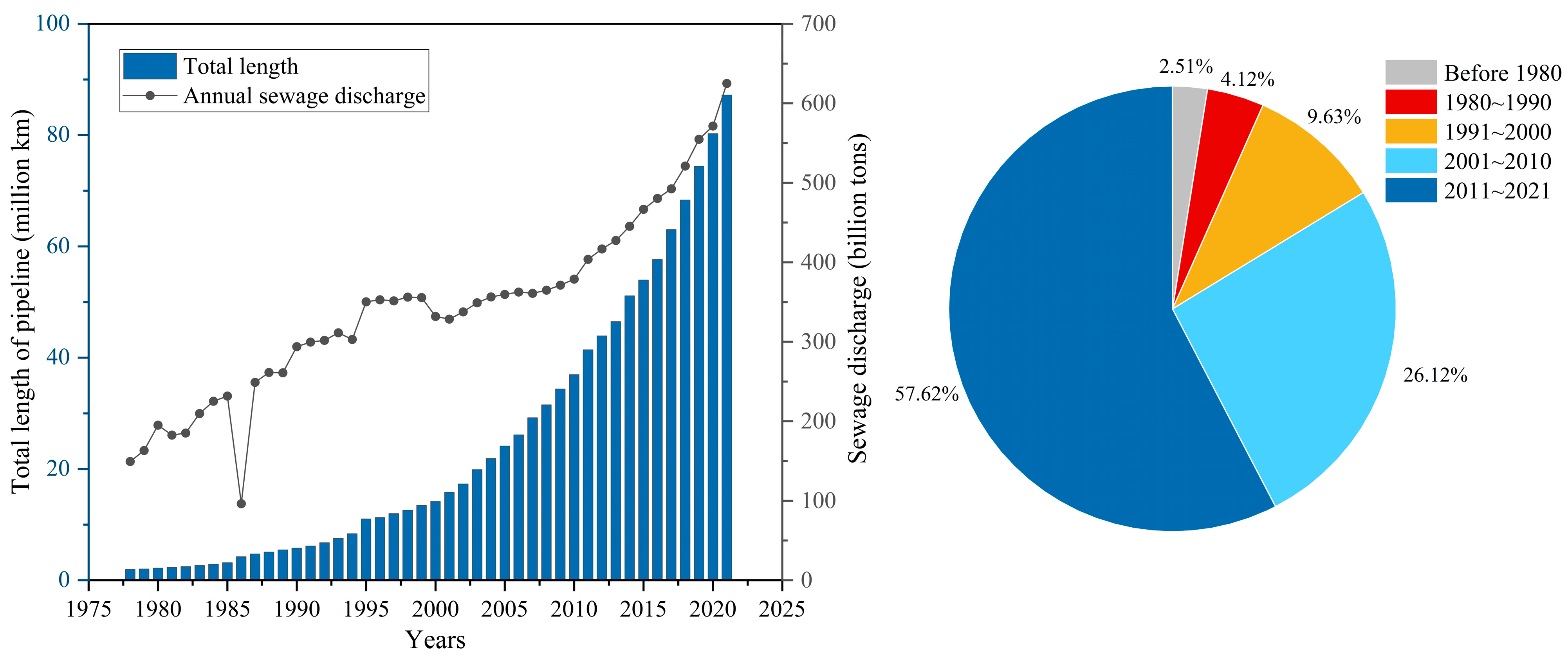
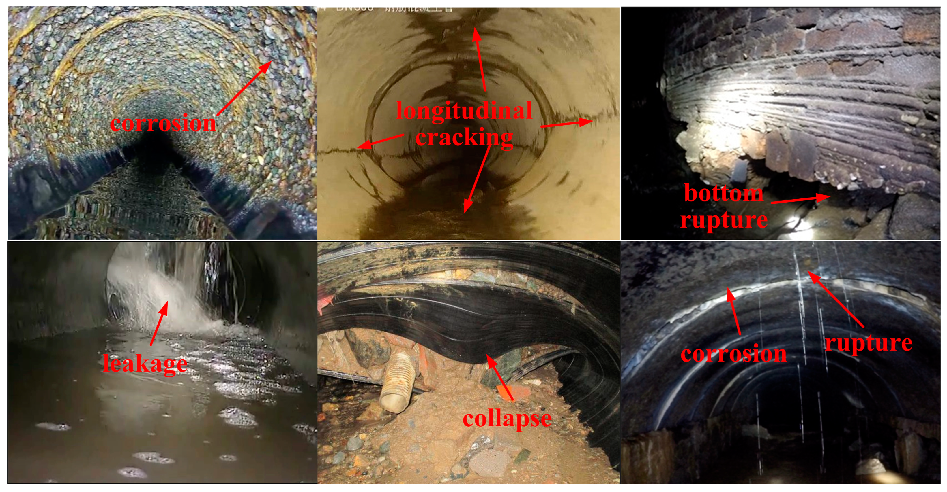
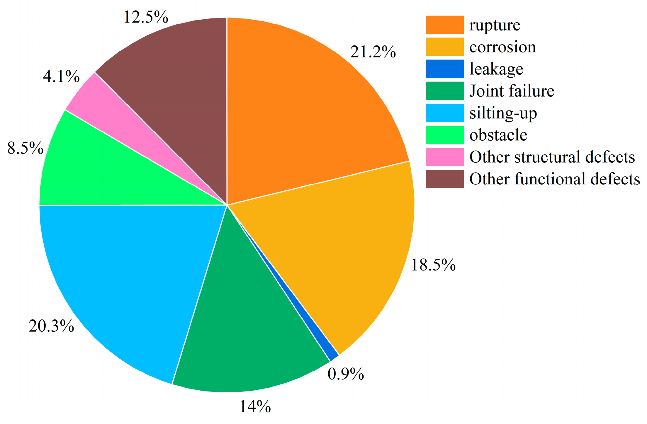
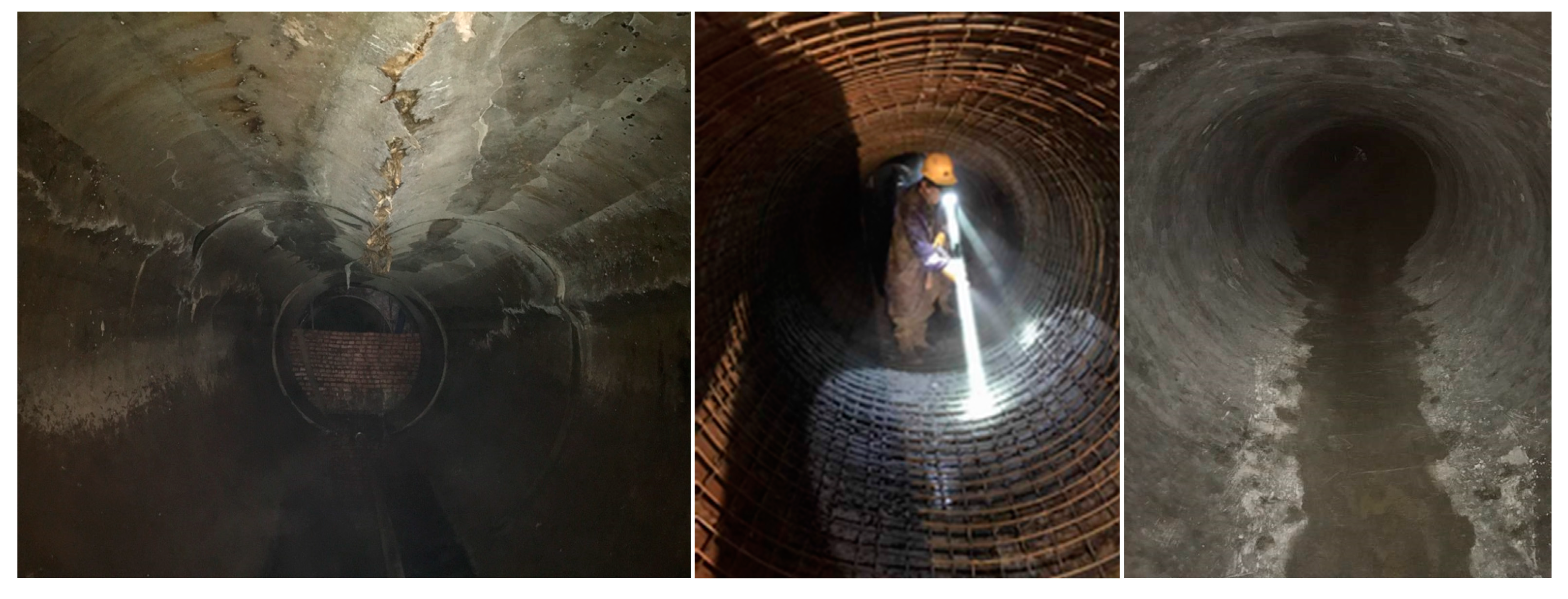
2.1. Service Environment and Defect Types of Drainage Pipes

Buried drainage pipes are exposed to long-term dampness and sulfate erosion, and are subjected to soil loads around the pipe, groundwater pressure, traffic loads, etc., resulting in various defects to the pipe during operation. Defect detection and defect level determination before pipe rehabilitation are crucial to rehabilitation. The most commonly used pipes for drainage in China are reinforced concrete, high-density polyethylene, and polyvinyl chloride. According to current inspection results, common defects in concrete pipes are corrosion and rupture (including longitudinal and circumferential cracking) (Figure 3), as well as leakage, disconnection, and foreign body penetration, while defects such as rupture and collapse are mostly found in plastic-type flexible pipes [6,7]. In addition to the commonly used circular pipes, some arch-shaped and rectangular drainage culverts built with materials such as bricks, stones, and concrete were constructed in the early days of urban construction. These culverts have been in operation for a long time and exhibit more serious defects such as leakage, corrosion, and collapse [28,29,30]. Furthermore, drainage culverts are prone to accidents such as soil erosion and ground collapse due to their large cross-sectional dimensions. The percentage of concrete pipe defects in a domestic city is shown in Figure 4.
The types of defects and causes of damage of drainage pipes have been summarized in some detail in several works; corrosion and rupture are the most common in drainage pipes in China [6,31]. Young et al. summarized the damage types of concrete pipes, mainly longitudinal cracks, circumferential cracks, and joint damage [32]. For the typical damage type of concrete pipes with longitudinal cracks, Ballinger studied the whole process of concrete pipes, from the initial laying to the final damage, through experiments [33]. The corrosion damage inside the concrete pipe is mainly due to the gradual formation of H2SO4 when the H2S gas in the pipe encounters condensed moisture, which rapidly corrodes the inner wall of the concrete pipe, leading to gradual thinning and exposure of the concrete pipe inner wall, reducing the service life of the drainage pipe [34,35,36].

2.2. Requirements for Material Properties of Cementitious Material Spraying Method

According to the common types of defects in drainage pipes, service environments, and structural performance requirements, domestic and foreign scholars have studied various aspects of spray repair materials for drainage pipes [16,17,21,37]. Drainage pipeline spraying repair materials are different from ordinary pipeline anticorrosion lining, mortar, or concrete materials for reinforcement of housing, bridges, etc. The lined pipeline has a complex working environment and needs to bear soil load and groundwater load, jointly or separately with the original pipeline, and requires good durability performance, with a service life of more than 50 years in general. China’s drainage pipe trenchless repair standards mainly set requirements for the setting time, compressive and flexural strength, acid resistance, and impermeability of cement mortar materials for spraying (Table 2), and the construction performance requires that the mixed slurry should be suitable for pumping and spraying, can be well bonded on the wet pipe wall surface, etc. [38]. Therefore, the material needs to have good flow properties, and the length of the fiber and the amount of admixture should not be too large.
In addition, in order to ensure that the original pipe and the liner work together, the mechanical properties Rm and Cs of the liner material and the original pipe material need to meet certain criteria to ensure that a good repair effect is achieved, as shown in Figure 5 [39].
Combined with the type of load mainly borne by the drainage pipe and the service environment, the main requirements for cementitious material for spray repair are as follows.
(1)
Strength of materials
The first requirement for cementitious materials for pipe repair is that the tensile, bending, and compressive strength of the material be higher than that of the original concrete pipe, e.g., compressive strength is generally >50 MPa, much higher than the performance of concrete pipes commonly used in China (compressive strength of ~30 MPa). Another is the elastic modulus of the two, and thermal expansion properties as close as possible. More research on the tensile and flexural properties of the liner is required. Some studies have shown that the mortar lining is mainly subjected to tensile stresses, and the initial damage occurs due to tension. Therefore, the material should have a high tensile strength and good toughness, ensuring that the lined pipe and the host pipe can be deformed in a coordinated manner [27,40].
(2)
Durability
Structural spray repair of cementitious materials generally requires a service life of >50 years, and durability is a key consideration for spray repair as sulfate and microbial corrosion are the main causes of structural strength reduction of concrete pipelines. Indoor corrosion tests have shown that the mechanical properties of high-performance cementitious materials are significantly reduced in the corrosive environment of drainage pipes, thereby reducing the effectiveness of spray repair [41]. At the same time, the material’s compactness and cracking resistance are factors influencing corrosion resistance. Therefore, cementitious materials for spray repair usually include various fibers to enhance the tensile strength of the material and fine aggregates such as microsilica powder, graded fine sand, and fly ash to increase the denseness of the material in order to increase the durability of the material. According to Wang’s research, the combined use of polyvinyl alcohol (PVA) fibers and magnesia expansion agent (MgO) can effectively solve the problems of concrete cracking and abrasion damage. Additionally, fly ash, fibers, MgO, and shrinkage-reducing admixtures can all improve the frost resistance of concrete [42,43,44].
(3)
Interfacial bonding performance
The effectiveness of the rehabilitated structure depends on the weakest part of the combined structure, and for the existing pipe-lined structure, the bonding performance of the interface has a major influence. Zhao et al. showed that the interface peeling between the cementitious materials liner and the original pipe under external load is the main reason for the failure of the combined structure [14,22]. Zhang proposed that the radial stress and shear strength of the interface are the conditions for the liner and the existing pipe to work together, and the presence of the interface gap causes the combined structure to show poorer performance when sharing the external load [27]. McAlpine’s study also showed that the liner alone cannot increase the load-bearing performance of the structure, and that the lined pipe needs to be bonded to the existing pipe as a whole, so as to achieve the purpose of improving the load-bearing performance of the repaired structure [40]. In addition, the plastic shrinkage and dry shrinkage strain of cementitious materials can lead to peeling of the interface. The addition of fly ash, microbeads, and mineral powder to cement mortar can all reduce the early shrinkage of cementitious materials, but the high dosing of silica fumes is not conducive to shrinkage control [45]. During the actual repair construction, measures such as high-pressure water cleaning and interface implantation of reinforcement should also be used to increase the bonding properties of the interface in order to improve the load-bearing capacity of the repaired structure.
(4)
Sprayability
The lining with sprayed cementitious materials rehabilitation method uses centrifugal or pressure spraying to ensure a good cement-based material evenly covers the host pipe inner surface to form a lined pipe. The cementitious material, under the action of compressed air, is transported through the feeding tube to the nozzle, so it must have good fluidity to ensure pumpability, no sagging, low resilience, and that the length of fibers and dosage are not too high.
(5)
Impermeability
Seepage resistance is the main control index to improve and ensure the durability of the structure. Buried pipelines are in an environment of moisture and water erosion for a long time, and the impermeability of lining materials is closely related to the material age, water–cement ratio, additives, etc. In addition, the impermeability is inseparable from the development of crack extension, so the anti-cracking performance, compactness, and self-healing performance of the material are currently focused on in more studies [46,47,48].

3. Research Progress of Fiber-Reinforced Cementitious Composites

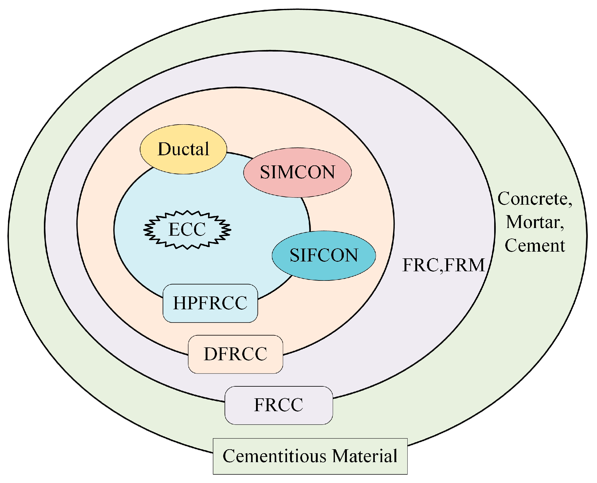
3.1. Introduction to Fiber-Reinforced Cementitious Composites

Since the 1960s, steel fibers, polypropylene fibers (PP), polyethylene fibers (PE), glass fibers and other fiber-reinforced concrete and mortar materials have been developed and applied—mixed into the fiber to limit the formation of cracks, growth, and chemical intrusion; or to solve the problems of poor tensile properties of traditional concrete and mortar materials, material shrinkage, and lack of durability. In the 1980s, the concept of high-performance concrete (HPC), with high strength, durability, and excellent performance was introduced in Europe and the United States. Research ensued related to Ultra-High Performance Concrete (UHPC), based on the mathematical model of maximum packing density theory, by adding millimeter-level aggregates, micron-level fine ash (fly ash, cement, mineral powder), submicron particles (silica fumes), fibers, and various additives—in theory, to achieve the maximum densities; its energy absorption, such as compressive and flexural resistance, is also significantly improved, but the tensile strain of UHPC is 0.2% or even lower [49,50]. The incorporation of fibers in cementitious materials is one of the most effective methods to improve the performance of cementitious materials toward light weight, high strength, high toughness, and high durability at present, gradually forming FRCC materials, which are rapidly developed and applied worldwide. The complex internal environment of buried drainage pipes is susceptible to chemical and microbial corrosion, and the trenchless repair requires the shortest possible construction period and early return to use, which requires the cementitious lining to have good structural strength, corrosion resistance, and fast-setting and early strength properties. To ensure the reliability of the structure for long-term use, it also needs to fit closely and bond well with the original pipe, and fiber-reinforced cementitious materials can meet these needs. When used for drainage pipe repair, these have an obvious effect of crack resistance, enhancement, and toughening, and can also increase the bonding strength between the lining and the original pipe to enhance the repair’s effectiveness.
Ultra-high-toughness cementitious composites (UHTCC) or engineered cementitious composites (ECC) are prepared by using cement, fly ash, and other industrial wastes as cementitious materials, forming a matrix with quartz sand, water, and a high-efficiency water-reducing agent, and then mixing with polyethylene (PE) fibers or polyvinyl alcohol (PVA) and other short-cut fibers as reinforcing materials. Compared with FRCC, High-Performance Fiber-Reinforced Composites (HPFRCC), etc., the ultimate tensile strain of ECC exceeds 3%, which is tens to hundreds of times higher than that of ordinary fiber-reinforced cementitious composites. ECC can be designed with different properties by adjusting the parameters of the matrix and fibers. The compressive strength of ECC using high-strength fibers can reach more than 200 MPa, and the elongation performance can exceed 12% [17,51,52]. Moreover, this material has small cracking gaps, good corrosion resistance, and some self-healing ability, which can significantly improve the durability of structures [53,54,55,56]. This type of material has been widely used in buildings such as dams and tunnels and has shown good reinforcement effects [37,57,58,59].
For the design of new materials, Li proposed an integrated platform for material design, structural design, and operation and maintenance, as well as an integrated structural material design approach (ISMD) (Figure 6), which theoretically links the macroscopic performance of the structure to the performance of ECC composites and the selection and optimization of ECC constituent materials [37,60]. This research approach is currently often used in the development of lining materials for spray repair, linking material design with the structural performance requirements of pipelines, in order to develop high-strength, high-toughness cementitious repair materials suitable for pipe repair.
Matsumoto and Mihashi classified cementitious composites (Figure 7) and introduced the basic concepts and characteristics of various Ductile Fiber-Reinforced Cementitious Composites (DFRCC) [61]. Although the names of these materials are defined differently in each country, the basic design concepts are similar, and new cementitious composites with excellent properties are developed through composition and structural optimization design. Since the properties of ECC materials are very much in line with the needs of drainage pipe repair by spraying, more and more studies have been conducted in recent years on this material in drainage pipe repair, which is also the most promising material for spraying repair [17,62]. The following is an overview of this material in relation to its matrix material, reinforcing fibers, and the fiber–matrix interface structure.

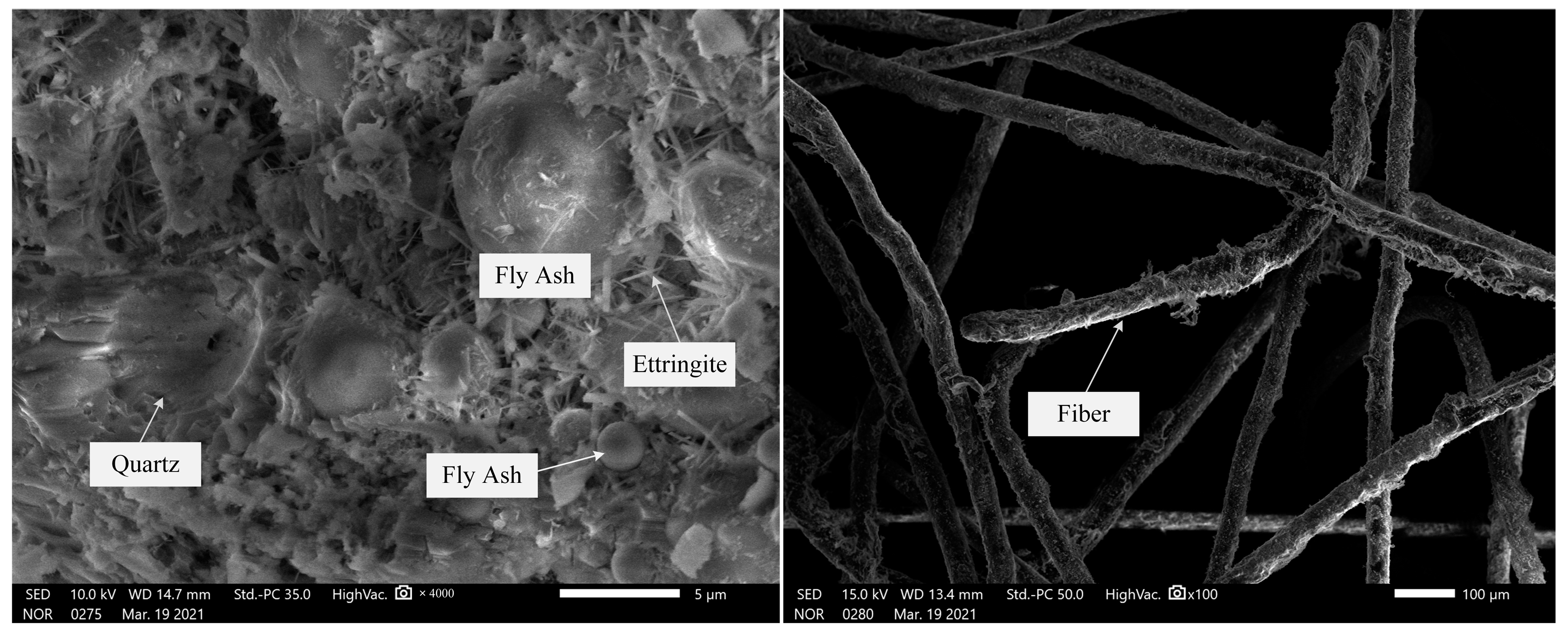
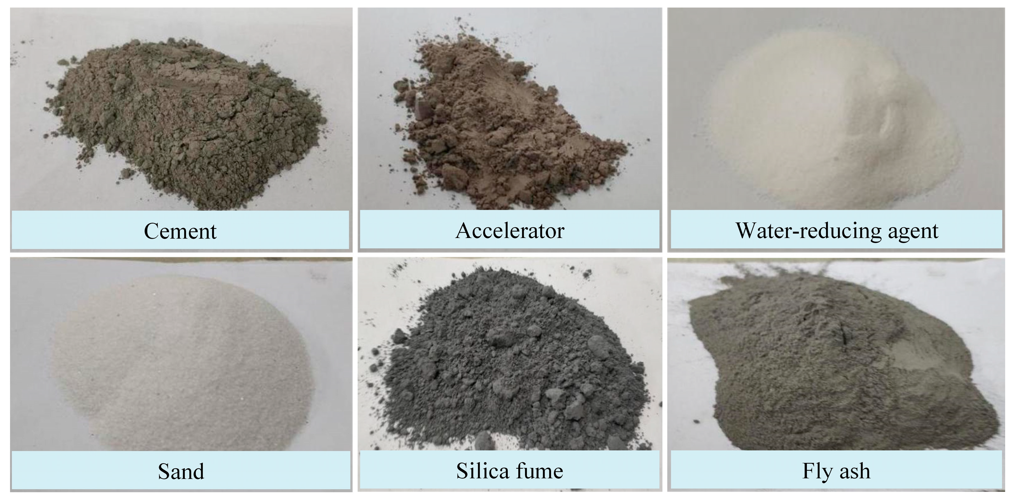
3.2. Matrix Materials

The micromechanical model of an ultra-high-toughness cementitious composite material is a three-phase composite material mechanical model composed of a matrix, fiber, and fiber–matrix interface; the material’s microstructure is shown in Figure 8 [37]. Its performance is closely related to the selection of materials such as cement, fly ash, graded quartz sand, water, water-reducing agents, and fibers. In the matrix material, cement is generally selected with higher silicate and aluminate cement grades, and fly ash is added to improve the material’s corrosion resistance and self-healing properties. The addition of fly ash can significantly improve the densification and strength of the material, while reducing the dry shrinkage rate of mortar and improving the material’s resistance to sulfate corrosion [63]. The study of Yang et al. shows that, although the addition of fly ash can greatly improve the shrinkage resistance of ECC materials, excessive amounts can reduce the compressive strength of ECC [64]. The water–cement ratio of ECC materials is generally around 0.25–0.3, which can be used as the basic proportion of ideal spray repair ECC materials [62,65]. In Kim et al.’s research, the sprayed ECC, as shown in Table 3, used aluminate cement to replace 5% of silicate cement, adjusted the rheological properties of ECC, shortened the material’s static stop time, and ensured its pumpability and spray bonding performance [66]. It has been proven that the material performance of the ECC material for spray construction is basically the same as that of the ECC material for mold construction, which shows that the ECC material has good sprayability [67]. Some commonly used matrix materials are shown in Figure 9. In order to ensure the effect of drainage pipe repair, various chemical additives are also added to the material to improve the performance of the repaired structure [68,69].

3.3. Fibers for Reinforcement

The selection of fibers for fiber-reinforced cementitious composites mainly considers the tensile strength, modulus of elasticity, elongation, and bonding with the matrix material of the fibers. The commonly used fiber types and parameters are shown in Table 4 [65,66].
Mortar with added fibers has excellent anticracking and strength enhancement effects, which can effectively prevent the emergence and expansion of structural cracks and develop the failure type from brittle damage to ductile failure. At the initial stage of bearing load, fiber and cement matrix work together; when the external load increases and cracks start to appear, stress is transferred from the matrix to the fiber through the interface, and the bridging role of the fiber starts to come to the fore, which obviously improves the toughness. The role of fibers is mainly to:
(1)
Improve the tensile and flexural strength, etc.
(2)
Improve the anticracking ability, effectively reduce cracks caused by the plastic shrinkage and dry shrinkage of the material, prevent the appearance of microcracks in the material, and delay the development of new cracks.
(3)
Improve the toughness and impact resistance of the material, bear the tensile stress at the location of the crack so that the material has good toughness.
(4)
Improve the seepage resistance, durability, etc. of the material.
The volume fraction, orientation, shape, size, and properties of fibers, as well as the bonding characteristics between the matrix and fibers, are important factors that affect fiber-reinforced cementitious composites. They need to be considered in the design of lining materials [70,71]. PP, PE, and PVA fibers are the most commonly used reinforcing fibers for ECC materials. The elastic modulus of the PP fiber is lower, and its elongation at the break is greater than that of concrete. Its addition can improve the ductility of the material and has an important role in the bearing capacity after cracking. The elastic modulus and tensile strength of PE fiber are higher than those of PP and PVA fibers. The tensile performance of PE-ECC materials is much higher than that of composite materials with PP and PVA fibers. The performance parameters of cementitious composites reinforced with PP, PE, and PVA fibers are shown in Table 5 [72]. Fibers with a high elastic modulus are mainly used to improve the material’s impact resistance, tensile and flexural strength, stiffness, and anti-cracking performance, while fibers with a slightly lower elastic modulus are mainly used to improve the material’s toughness and strain capacity. Lai et al. studied the influence of PP fiber length and dosage on the flow performance of the material. The results showed that fiber length had a significant effect on the flowability of mortar within the range of 6–12 mm. The fiber dosage was negatively correlated with flowability, and the mass ratio of fiber dosage generally should not exceed 0.9%. The study also showed that mortar materials containing PP fibers can achieve good flowability with reasonable design proportions, which is beneficial for spray construction [73]. On the other hand, Pereira et al. studied the effect of fiber diameter on the initial cracking strength. Fibers with smaller diameters significantly improved the initial cracking strength of the material, while fibers with larger diameters often played a significant role only after cracks formed, showing more obvious tensile hardening characteristics [74]. The carbonation resistance of concrete is also an important factor affecting the durability of structures. Relevant tests have shown that when the length of PVA fiber is 6 mm and the fiber volume content is 0.75%, the improvement of the carbonation resistance of concrete is the strongest [75].

3.4. Fiber–Matrix Interface

Ultra-high-toughness cementitious composite materials exhibit significant strain-hardening characteristics, excellent strength, and toughness through the rational design of matrix materials, fiber parameters, and interface properties. The effectiveness of fiber-reinforced cementitious composites’ mechanical properties largely depends on the interaction between the fiber and matrix, mainly the physical and chemical bonding strength, frictional bonding strength, and mechanical anchoring effect caused by fiber shape change [76,77]. For example, PVA fibers are widely used in ECC materials because they are hydrophilic materials, and their surfaces can form strong chemical bonds with cement matrix, while PE and PP fibers have very weak adhesion to the matrix, and relative slippage easily occurs. To improve the toughness of fiber-reinforced composites, the fiber shape can be changed or the fiber surface can be treated. For example, surface coating can be used to change the fiber’s hydrophilic properties and obtain ideal interface properties [77,78]. Plasma treatment of polyethylene fibers can significantly improve the fiber–matrix interface bonding strength, as well as the tensile strength and strain energy of the specimens [79,80].
The stress transfer mechanism between the fiber and matrix material is different before and after cracking when the fiber-reinforced cementitious composites members bear the load. Before cracking, the fiber and matrix material have very little deformation and are in the elastic deformation stage, and they can generally achieve coordinated deformation and shared stress. Because of the different mechanical properties of the fiber and matrix material, the size of the load borne is also different. At this stage, the shear stress appears at the fiber–matrix interface, which is the main factor to consider with regard to crack development. As the deformation increases with the load, the fiber and matrix interface exhibit slip and debonding, and the fiber provides a bridging effect for the component to suppress crack expansion and occurrence. The ultimate strength of fiber-reinforced cementitious composite components appears in this stress transfer mode. The fiber–matrix interface bonding parameters are usually determined by single-fiber pull-out tests, and the fiber–matrix debonding model is determined based on experiments and fracture mechanics methods, providing a basis for the study of cracking mechanisms and material design [81,82].

4. Performance of Repaired Structures

4.1. Structural Performance Testing of Combined Beams

The load-bearing capacity and durability of the rehabilitated structure are the main evaluation indexes of the rehabilitation effect. For the structural performance after repair, domestic and foreign scholars mainly carried out composite beam loading, a three-edge bearing test, and a buried pipe test, and conducted research on the load-bearing performance and interfacial bonding performance of the combined beam and repaired pipe [14,83,84].
The performance of concrete structural repair and reinforcement depends on the bonding quality between the repair material and the substrate material. The interfacial bonding force between new and old structures is composed of mechanical interlocking force, van der Waals force, and chemical action. Currently, measures such as adding cement slurry, an interface treatment agent, and anchoring reinforcement are often used to improve interfacial bonding performance on the existing structure surface. Lim et al. studied the bonding behavior between ECC and the concrete substrate interface using concrete beams with T-shaped notches, which showed that ECC repair and reinforcement can prevent the delamination and peeling of composite structures, and proposed a crack propagation mechanism of ECC and the concrete interface [85]. Wang et al. studied the bending performance of reinforced concrete beams with UHTCC reinforcement through four-point bending tests, and the cracks during the loading process of the composite structure were relatively fine, showing obvious ductile failure. After reinforcement, the structural ductility and load-carrying capacity were significantly improved [86]. Kim et al. conducted bending tests on reinforced concrete beams with sprayed ECC and compared them with other mortar materials. After ECC spray repair, the interfacial performance and energy absorption capacity were better, and the enhancement effect on the load-carrying capacity and ductility of the composite structure was good, which can effectively extend the service life of the repaired structure [48]. Zhang and Zhao et al. studied the judgment criteria for the collaborative work of the original pipeline–inner lining structure after repair through indoor composite beam bending loading tests and theoretical calculations, namely the relationship between the shear strength and bonding tensile strength of the interface and the interfacial shear stress and radial tensile stress. When the resistance is greater than the load, a laminated structure is formed; otherwise, a composite structure is formed [14,27].
Kamada et al. conducted bending tests on reinforced concrete beams with ECC and investigated the effect of concrete surface roughness on the fracture behavior of composite structures. The results showed that smoother concrete surfaces were more favorable for the long-term use of repaired structures [87]. Xie et al. divided the interface between new and old concrete into a permeation layer, a strong influence layer, and a weak influence layer, and discussed the relationship between the microscopic structure of the interface and the macroscopic mechanical properties [88]. Qian et al. proposed a test method using a conical hole specimen to evaluate the bonding properties of cementitious repair materials and compared it with the existing bending method. The bonding performance was evaluated by examining the bonding appearance and testing the permeability of the interface and the bonding strength [89]. Xu et al. studied the interface bonding behavior between sprayed ultra-high-toughness cementitious composite materials and concrete structures, and showed that the spraying direction and surface roughness had a significant effect on the interface bonding performance. It was also pointed out that the thickness of a single continuous spraying should not exceed 25 mm during spraying construction, and layer-by-layer spraying should be used for thicknesses greater than 25 mm [90]. Huang found that, as the thickness of the UHTCC layer increased, the stiffness, yield load of steel bars, and ultimate load of beam specimens also increased, and the occurrence of cracks in the concrete layer could be effectively controlled after spraying. In addition, layer-by-layer spraying construction of the reinforced layer did not affect the reinforcement effect compared to the single-layer spraying process [59].
Split tensile strength testing, direct tensile strength testing, and shear testing of cubic specimens are also commonly used to evaluate the bond strength of interfaces. Cheng et al. systematically studied the bonding between fiber-reinforced concrete and substrate concrete through experimental research, exploring the basic mechanical properties of shear and split tensile strength as well as the antifreeze and antiseepage capacity and durability of the bonding surfaces [91]. Wang et al. studied the tensile bond strength between UHTCC and concrete substrate through pull-out tests, investigating the influence of the interface roughness, substrate strength, interface bonding agent, and other factors on the tensile bond strength, and showing that improving substrate strength, reasonable substrate surface roughness, and interface bonding agent are favorable for forming a good bond at the interface [92]. Interfacial implantation of reinforcement has also been used to increase the interfacial bond strength. Yang et al. studied the mechanical properties of the reinforced UHPC–masonry interface, showing that the failure mode of unreinforced UHPC–stone combination specimens is brittle, while the reinforced specimens exhibit ductile failure mainly characterized by interface slip and local stone splitting, and the interface shear strength is significantly increased after reinforcement [93].
From a previous study, we know that the bonding performance of the interface has a significant impact on the strengthening effect of structures. However, currently, few measures are taken to enhance the bonding strength of the interface before repair construction, and most of them only use high-pressure water washing, which has limited synergistic performance between the original pipeline and the lining. More measures should be taken to increase the bonding performance of the interface between the lining and the pipeline, such as increasing the roughness of the inner wall of the pipeline through mechanical action, implanting a reinforcement at the interface, adding a wire mesh, and increasing the use of interface treatment agents to improve the shear, tensile, bending, etc. performance of the interface. For repairing drainage pipelines that require a thicker lining, a layered spraying method should be adopted.

4.2. Three-Edge Bearing Test

For the rehabilitation of drainage pipes by cementitious materials spraying, excellent load-bearing performance after rehabilitation is the goal of material development and is a great concern for management, designers, and construction personnel. Cementitious materials development should consider the need for material performance in conjunction with the force model of the pipe–lining structure. A three-edge bearing test is often used to evaluate the load-bearing performance and defect level of drainage pipes before and after rehabilitation, which provides a reference for lining design and structural performance evaluation.
Najafi et al. studied the changes in the load-bearing capacity of a 610-mm-diameter reinforced concrete pipeline after repair, and found that the use of cementitious lining with thicknesses of 12.7 mm and 25.4 mm increased the load-bearing capacity by 25% and 77%, respectively [94]. Kang et al. found that a cementitious lining greatly reduced the stress on the steel corrugated pipe and, under external loads, the top of the lining was most likely to produce tensile cracks. Therefore, the design control parameter was the tensile strength of the lining, rather than deformation [95]. Zhao et al. repaired a 1000-mm-diameter reinforced concrete pipeline with four longitudinal cracks using spray repair, and tested the performance changes of the repaired structure through three-edge bearing tests. They pointed out that there were differences in the repair effects given different deformation amounts of the original pipeline. When the deformation amount was less than 2.7%, the repair effect was better, and the structural strength with a 50 mm lining was greater than the ultimate bearing capacity of the original pipeline. When the deformation amount was greater than 2.7%, the repaired structural strength was still lower than that of the original pipeline [14]. Zhu and Wang et al. used ECC to repair concrete pipelines, and the test results showed that the load-bearing capacity of the repaired structure was about four times that of the original pipeline, and the antipermeability performance was better [17,62]. Fan et al. carried out spray repair and reinforcement on reinforced concrete pipelines with different degrees of damage (70%, 80%, and 90% of the ultimate load), and found that the ultimate bearing capacity of the repaired pipeline increased by 50.6%, and the lining did not separate from the original pipeline [96]. Wang et al. used H-70 cement mortar to spray reinforce damaged shield tunnel segments, and full-scale loading test results showed that the ultimate bearing capacity of the structure increased by 10% after reinforcement [15]. The test results of Entezarmahdi et al. showed that the flexural and compressive properties of concrete pipes were significantly improved after repairing with cementitious materials [97].
According to a previous study, the rehabilitation of drainage pipes with different degrees of defects can achieve different rehabilitation results. The probability of failure of buried pipes during service can be described according to the bathtub curve (Figure 10), which shows that the probability of failure of the original pipe increases gradually with an increase in service time; the probability of failure increases significantly beyond the normal service stage and the remaining bearing capacity becomes smaller and smaller. Choosing a reasonable time to repair, at or before the failure stage, is conducive to extending the service life of the pipeline. On the contrary, when the original pipeline has more serious damage, the repair requires a higher wall thickness and cannot make full use of the remaining bearing capacity of the existing pipeline and the ability of the two to work together, and the service life is not significantly improved.

4.3. Soil–Pipe–Liner Structural Performance

Pipe soil model tests can simulate the actual stresses on buried pipes and provide a reference for repair design. Law and Moore proposed the concept of a soil–host pipe–lining pipe interaction when they studied the structural performance of HDPE-lined repair of damaged plain concrete pipes [98]. It was shown that the stiffness contributed by the soil on the pipe side was approximately twice the stiffness contributed by the liner and the liner plus a grouting layer [99]. Moore et al. conducted cementitious material spray repair tests on internally corroded steel-walled corrugated pipes and showed that the flexural stiffness of the pipe section increased after the spray repair and the bending moment of the original pipe section decreased. The study pointed out that the original pipe and the cement mortar lined pipe are not fully bonded and so cannot work together, and the tensile strength of the liner is only 7% and 13% of the ultimate tensile strength of the material when the liner is 76 mm and 51 mm. The bonding effect between the two should be ignored for conservative calculations during the repair design. It has been proposed that the damage mode of cement mortar lining is brittle rupture due to circumferential bending, and that lined pipes are not susceptible to buckling [83,100,101]. Zhang et al. studied the effects of traffic load, earth pressure, and groundwater load on the structural performance of concrete pipes repaired by cement mortar spraying, showing that traffic load and earth pressure have a large effect on the structural bearing performance. The spraying repair can reduce the stress concentration in the corroded area of the pipe and restore the load-bearing performance of the original pipe to even greater than that of the original pipe [102,103]. Tetreault et al. conducted spray repair of corrugated steel pipes buried at a depth of 0.45 m with artificial corrosion and tested the structural performance of the pipe under traffic load before and after the repair. The study showed that the ultimate load carrying capacity of the rehabilitated pipe increased from 1325 kN to 1600 kN [104]. Other studies have shown that the damage deformation of the original pipeline is relatively small, and the lining pipeline bears very little earth pressure [105]. However, for buried pipelines, the study of soil–pipe interactions is necessary for accurate rehabilitation design and prolonging the service life of the structure.

5. Wall Thickness Design of Liner

Although a large number of structural performance tests and theoretical studies have been conducted previously, there is no fully unified method for liner wall thickness design. Bazant et al. considered the size effects of fracture mechanics and proposed a method for calculating the thickness of concrete beams and rings [106]. According to the different damage types of the original pipe classified in ASTM F1216, Matthews proposed a method for calculating the wall thickness of geopolymer cement mortar lining for partially damaged and completely damaged pipes [107]. Royer et al. considered the effects of safety factor and original pipe ellipticity and proposed a theory of liner wall thickness calculation under different force models based on the study of Young and Watkins [108,109,110]. The ASTM F1216 calculation method for CIPP liner wall thickness design was also used in the wall thickness design of cementitious lining [111]. The abovementioned liner wall thickness calculation theories have been applied in different situations. Some of the cementitious liner wall thickness calculation methods are shown in Table 6.
However, these design methods do not explicitly consider the effect of secondary stress on the pipeline structure. Before repair, the drainage pipeline has already been subjected to loads such as soil pressure, traffic load, and groundwater pressure, and the pipe wall structure has already reached a high stress level and undergone deformation. The internal forces of the pipe wall can be calculated using traditional structural mechanics methods. After repair, the weight of the inner lining layer is borne by the original structure. Assuming that the original structure’s load-bearing capacity does not change, the inner lining pipeline can be considered to only bear the part of the load that increases after partial repair, such as newly added ground loads and traffic loads, and does not participate in sharing the loads that already existed before the repair. Therefore, the repair process of drainage pipelines belongs to the category of secondary stress structures, which can cause significant differences in the stress models of existing pipeline–inner lining structures. Although Shi et al., based on experimental results using the helical winding method, showed that the difference between secondary stress and primary stress is small, the crack load and failure load under secondary stress conditions are about 97.3% and 87% of the primary stress model, respectively, and therefore the effect of secondary stress can be considered negligible [112]. However, for pipelines with different types of defects, the extent of the effect of secondary stress has not yet been determined and further research is needed.

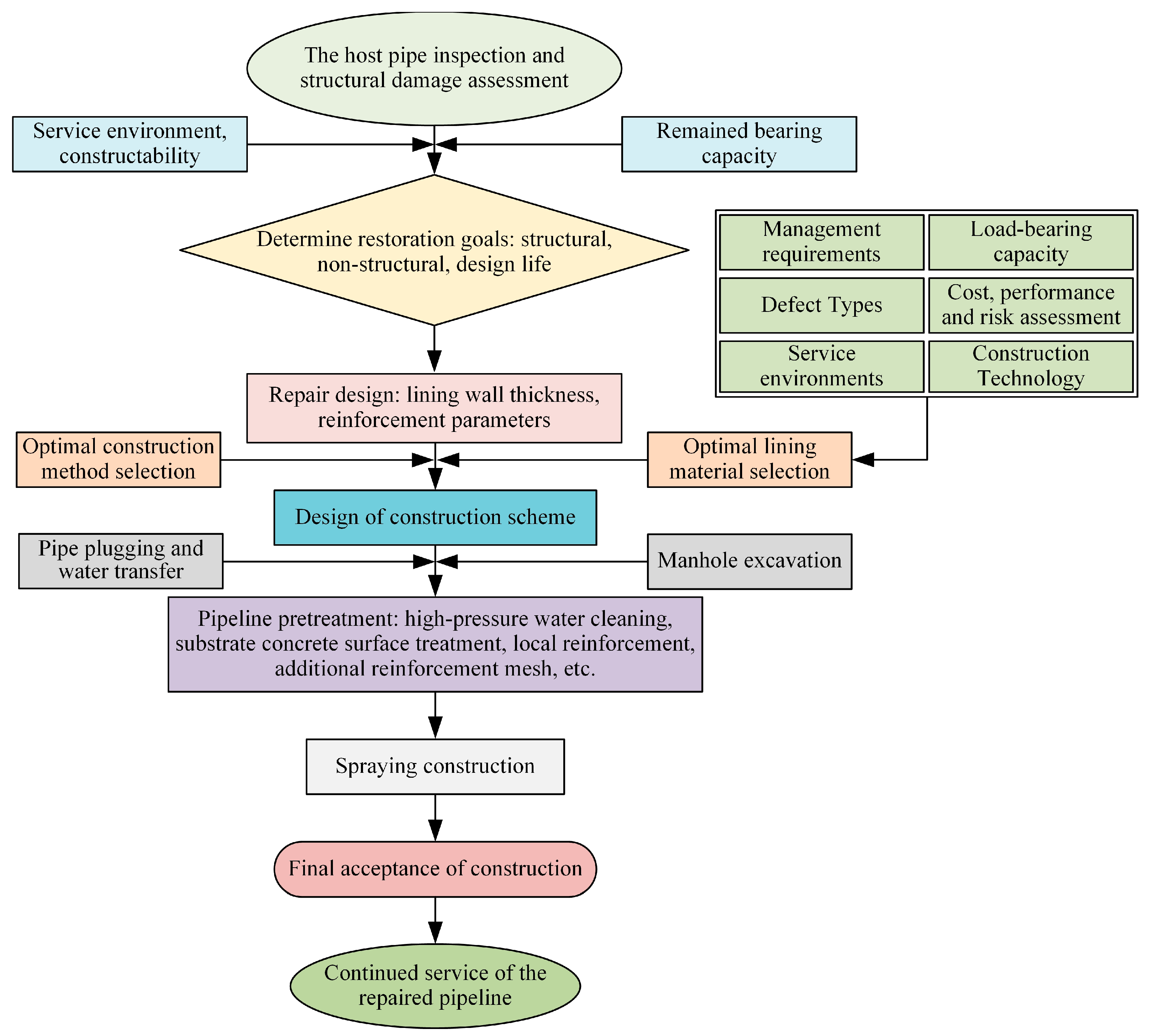
6. Lining with Sprayed Cementitious Materials

The main advantage of lining with sprayed cementitious materials is that the construction is flexible, the repair effect is reliable, the lining fits closely with the original pipe, and the overflow capacity and structural bearing performance of the original pipe can be significantly improved. For round pipes, centrifugal spraying equipment can be used for automatic spraying repair, and for rectangular, arched, and other shapes of culverts, manual spraying can be used for construction. In addition, it is possible to assign the spraying thickness flexibly according to the defect level, and decide whether to add reinforcement mesh as needed to meet the structural repair needs.
Lining with sprayed cementitious materials is widely used in China’s drainage pipes, box culverts, inspection wells, and other infrastructure, and is applicable to the structural repair of various drainage pipes with diameters from 300 to 3000 mm. When the pipe diameter is less than 600 mm, it can be repaired by automatic centrifugal spraying, with a single spraying thickness of 30 mm and a spraying length of 120 m or more. For a project DN300 reinforced concrete drainage pipe that has been operating for 25 years, there is serious corrosion, leakage, and other defects; the pipe situation before and after the use of centrifugal spraying repair is shown in Figure 11. For a large-diameter drainage pipe, manual spraying repair can be used with distances up to 600 m. The technology to repair a formation of uniform and dense lined pipes, the original pipe to form a good bond, and flexible construction, can be used for bending, misalignment, and other special location repair, with the lining thickness determined according to the actual defects in the specific parts of the adjustment, according to the structural defects that are to be reinforced.
The spraying method has been used frequently for the rehabilitation of drainage pipes of other types in China; e.g., when the original pipe is FRP sandwich class with a smooth surface or poor structural performance, the overall performance of the original pipe and the lined pipe can be increased by adding a steel wire mesh to improve the structural bearing capacity after repair. For example, in Chongqing, for a 2000 mm diameter FRP pipe with internal rupture, collapse, and other structural defects, to the original pipe was added a layer of 8 mm diameter spacing of 100 mm reinforcement mesh, and after MS-10000 material manual spraying repair to good operating condition, the wall thickness of the liner was 80 mm, as shown in Figure 12. In addition, the cement-based material spraying method is often used for the rehabilitation of drainage pipe manholes in China (Figure 13).
At present, most drainage pipe rehabilitation only uses CCTV inspection to artificially determine the type and grade of defects, and then calculates the wall thickness according to the standard, without detailed consideration of the service environment and remaining strength of the pipe, so the design and rehabilitation construction are unreasonable. After detailed inspection, the remaining bearing capacity of the original pipe should also be judged, the service environment of the lining material should be determined, and specific rehabilitation targets should be identified to design the wall thickness, reinforce the mesh parameters of the lining, etc. When selecting cementitious materials, the type of defects, bearing capacity, and construction technology of the original pipeline should also be taken into consideration. A refined rehabilitation design is more conducive to improving structural safety performance and reducing construction costs. The main construction process of this technology should be carried out according to Figure 14. When using fiber-reinforced cementitious composite material spraying to repair drainage pipes, the inner wall of the original pipe needs to be thoroughly clean and without any loose debris, and there should be no water seepage in the pipe. The thickness of one spraying should be less than 30 mm, and the lining wall thickness should be sprayed in layers when it is too large. Attention should also be paid to the influence of temperature and humidity; otherwise, these can have a great impact on the performance of the material.

7. Conclusions

The method of lining with sprayed cementitious materials can be used for various types of drainage pipe rehabilitation and is currently used in infrastructure such as subway tunnels and utility tunnels. Through a comprehensive study of cementitious materials’ post-rehabilitation structural performance, rehabilitation design, and construction, the following main conclusions were reached.
(1)
When the method of lining with sprayed cementitious materials is used for drainage pipe repair, the repair effect is closely related to the performance of the lining material. The lining material for rehabilitation should have excellent structural strength, durability, impermeability, sprayability, etc., and can be firmly bonded and synergistically stressed with the original pipe.
(2)
Research on fiber-reinforced cementitious composites for spray repair should be conducted in terms of three aspects: matrix material, reinforcing fiber, and the role of the fiber–matrix interface. It is also necessary to design the material properties in conjunction with the structural stresses of the lined pipe and according to the actual needs of the structure.
(3)
Ultra-high-toughness cementitious composites with excellent toughness, structural strength, and durability in the drainage pipe spray repair have gradually begun to be applies. The use of ultra-high-toughness cementitious composites is conducive to the repair of the structure to bear the load and improve the overall service life of the structure.
(4)
Although there have been a large number of structural performance tests and theoretical pieces of research, there is no fully unified lining wall thickness design method. A buried pipeline–nonexcavation repair lining system is a secondary force structure; there has been no research in this area and so further theoretical and experimental work is needed.
(5)
Fiber-reinforced cementitious composite spraying technology can be used for the repair of drainage pipes of various section shapes and sizes, with flexible construction and reliable repair results, and can lay reinforcement mesh and design wall thicknesses as required, which has obvious advantages when used for the nonexcavation repair of urban drainage pipes.
In the future, as a large number of drainage pipes in China reach the end of their service life, the demand for fiber-reinforced cementitious composite lining materials will gradually increase. Considering the change of service environment and the demand of structural performance, it is necessary to further develop high-performance fiber-reinforced cementitious composites, such as underwater dispersion-resistant mortar, and construction with water spraying. In terms of indoor tests, there have been few studies considering the overall soil–pipe–liner structure and secondary stresses on the structure, and even fewer studies on in situ testing in the field. It is recommended that further relevant tests and theoretical studies be conducted to provide better information for the assessment of structural performance and liner wall thickness design after repair.

Author Contributions

Conceptualization, S.D.; formal analysis, C.G. and H.Z.; investigation, S.D.; resources, E.H.; writing—original draft preparation, S.D.; writing—review and editing, S.D. and Y.T.; supervision, E.H.; project administration, D.W.; funding acquisition, S.D. All authors have read and agreed to the published version of the manuscript.

Funding

This research was funded by the project “Research on cementitious material for drainage pipe rehabilitation and liner thickness estimation” of the China Three Gorges Corporation (Program No. WWKY-2021-0275).

Data Availability Statement

Not applicable.

Conflicts of Interest

The authors declare no conflict of interest.

References

  1. Li, B.; Yu, W.; Xie, Y.; Fang, H.; Du, X.; Wang, N.; Zhai, K.; Wang, D.; Chen, X.; Du, M.; et al. Trenchless Rehabilitation of Sewage Pipelines from the Perspective of the Whole Technology Chain: A State-of-the-Art Review. Tunn. Undergr. Space Technol. 2023, 134, 105022. [Google Scholar] [CrossRef]
  2. Najafi, M.; Gokhale, S.; Calderón, D.R.; Ma, B. Trenchless Technology: Pipeline and Utility Design, Construction, and Renewal; McGraw-Hill Education: New York, NY, USA, 2021; ISBN 1-260-45873-3. [Google Scholar]
  3. Zhao, Y.; Ma, B.; Ariaratnam, S.T.; Yan, X.; Xiang, W.; Zhu, Z.; Li, Z.; Moghbel Esfahani, M. Buckling Behaviour of Internal Stiffened Thin-Walled Stainless Steel Liners under External Constraints. Tunn. Undergr. Space Technol. 2022, 129, 104685. [Google Scholar] [CrossRef]
  4. He, C.; Yan, X.; Ma, B.; Zhao, Y. Experimental and numerical simulation of formed-in-place pipe liner for repairing water mains with void. Tunn. Undergr. Space Technol. 2022, 130, 104752. [Google Scholar] [CrossRef]
  5. Zeng, Z.; Yan, X.; Xiang, W.; Zhao, Y.; Ariaratnam, S.T. Buckling Behavior of Loosely Fitted Formed-In-Place Pipe Liner in Circular Host Pipe under External Pressure. Appl. Sci. 2023, 13, 679. [Google Scholar] [CrossRef]
  6. Ma, B.S. Trenchless Pipeline Rehabilitation and Renewal Technology; China Communications Press: Beijing, China, 2014; ISBN 978-7-114-11364-2. [Google Scholar]
  7. Zhu, Z.; Zhang, P.; Ma, B.; Zeng, C.; Zhao, Y.; Wang, F.; Li, Z.; Xiang, W.; Ariaratnam, S.T.; Yan, X. Quantitative model for residual bearing capacity of corroded reinforced concrete pipe based on failure mode. Tunn. Undergr. Space Technol. 2022, 129, 104675. [Google Scholar] [CrossRef]
  8. Yahong, Z.; Sheng, H.; Baosong, M.; Cong, Z.; Xuefeng, Y.; Zhongsen, T.; Han, L.; Caiying, D. Experiment and Evaluation Model of Liner Design for Renewal of Deteriorated Reinforced Concrete Pipes Utilizing Cured-in-Place-Pipe Technology. Tunn. Undergr. Space Technol. 2023, 132, 104866. [Google Scholar] [CrossRef]
  9. Ma, B.S.; Najafi, M. Development and Applications of Trenchless Technology in China. Tunn. Undergr. Space Technol. 2008, 23, 476–480. [Google Scholar] [CrossRef]
  10. Serajiantehrani, R.; Najafi, M.; Malek Mohammadi, M.; Kaushal, V.; Jalalediny Korky, S. Construction Cost Analysis of Trenchless Cured-in-Place Pipe and Spray-Applied Pipe Linings Rehabilitation Methods in Gravity Conveyance Conduits. In Proceedings of the Pipelines 2021, virtually, 3–6 August 2021; pp. 210–220. [Google Scholar]
  11. Yan, X.; Deng, C.; Zhao, Y.; Liu, H.; Mei, S. Mechanical Performance Study of Pipe-Liner Composite Structure Based on the Digital Image Correlation Method. IEEE Trans. Instrum. Meas. 2022, 72, 1–12. [Google Scholar] [CrossRef]
  12. Walker, K.R. Five Trenchless Rehab Projects Save Failing Large Diameter Combined Sewer Structures in Albany, NY. In Proceedings of the Pipelines 2020, San Antonio, TX, USA, 6 August 2020; American Society of Civil Engineers: Reston, VA, USA; pp. 427–432. [Google Scholar]
  13. Shook, W.E.; Arold, R.M.; Shepherd, R.M. Trenchless Rehabilitation Saves Grottoes, VA, Culverts—And Money—Without Disrupting Traffic. In Proceedings of the Pipelines 2015, Baltimore, ML, USA, 17 August 2015; American Society of Civil Engineers: Reston, VA, USA; pp. 171–179. [Google Scholar]
  14. Zhao, Y.H.; Ma, B.S.; Ariaratnam, S.T.; Zeng, C.; Yan, X.F.; Wang, F.Z.; Wang, T.Y.; Zhu, Z.H.; He, C.L.; Shi, G.P.; et al. Structural Performance of Damaged Rigid Pipe Rehabilitated by Centrifugal Spray on Mortar Liner. Tunn. Undergr. Space Technol. 2021, 116, 104117. [Google Scholar] [CrossRef]
  15. Wang, F.Z.; Zeng, C.; Ma, B.S.; Gong, C.K.; Liao, B.Y.; Zhao, Y.H.; Ma, C.; Kong, Y.Z. Experimental Investigations of a Tunnel Lining Segment Strengthened by In Situ Spraying Mortar. Appl. Sci. 2022, 12, 3722. [Google Scholar] [CrossRef]
  16. Wang, T.; Zeng, C. Study of Cement-Based Superhydrophobic Composite Coating: New Option for Water Drainage Pipeline Rehabilitation. Materials 2020, 13, 5004. [Google Scholar] [CrossRef] [PubMed]
  17. Zhu, H.; Wang, T.; Wang, Y.; Li, V.C. Trenchless Rehabilitation for Concrete Pipelines of Water Infrastructure: A Review from the Structural Perspective. Cem. Concr. Compos. 2021, 123, 104193. [Google Scholar] [CrossRef]
  18. Zhu, H.; Zhang, D.; Li, V.C. Centrifugally Sprayed Engineered Cementitious Composites: Rheology, Mechanics, and Structural Retrofit for Concrete Pipes. Cem. Concr. Compos. 2022, 129, 104473. [Google Scholar] [CrossRef]
  19. Spiesz, P.; Hunger, M. Structural Ultra-Lightweight Concrete–from Laboratory Research to Field Trials. In Proceedings of the 11th High Performance Concrete Conference, Tromsø, Norway, 6–8 March 2017; pp. 1–10. [Google Scholar]
  20. Valikhani, A.; Jahromi, A.J.; Mantawy, I.M.; Azizinamini, A. Experimental Evaluation of Concrete-to-UHPC Bond Strength with Correlation to Surface Roughness for Repair Application. Constr. Build. Mater. 2020, 238, 117753. [Google Scholar] [CrossRef]
  21. Kong, Y.Z. Study and Application of Cast In-Situ Method for Pipeline and Manhole Trenchless Rehabilitation. Doctoral Thesis, China University of Geosciences, Wuhan, China, 2017. [Google Scholar]
  22. Zhao, Y.; Ma, B.; Zhang, H.F. Mechanical Behavior and Calculation Method of Interface between Host Pipeline and Lining. J. Harbin Inst. Technol. 2020, 52, 167–174. [Google Scholar] [CrossRef]
  23. Morgan, D.R. Compatibility of Concrete Repair Materials and Systems. Constr. Build. Mater. 1996, 10, 57–67. [Google Scholar] [CrossRef]
  24. Kosednar, J.; Mailvaganam, N.P. Selection and Use of Polymer-Based Materials in the Repair of Concrete Structures. J. Perform. Constr. Facil. 2005, 19, 229–233. [Google Scholar] [CrossRef]
  25. Pattnaik, R. Investigation into Compatibility between Repair Material and Substrate Concrete Using Experimental and Finite Element Methods. Ph.D. Thesis, Clemson University, Clemson, SC, USA, 2006. [Google Scholar]
  26. Su, N.; Lou, L.; Amirkhanian, A.; Amirkhanian, S.N.; Xiao, F. Assessment of Effective Patching Material for Concrete Bridge Deck -A Review. Constr. Build. Mater. 2021, 293, 123520. [Google Scholar] [CrossRef]
  27. Zhang, H.F. Theoretical and Experimental Study on Structural Performance of the Sprayed-On Cement Mortor Liners Rehabilitaing Precast Concrete Drainage Pipe. Ph.D. Thesis, China University of Geosciences, Wuhan, China, 2019. [Google Scholar]
  28. Piratla, K.R.; Jin, H.; Yazdekhasti, S. A Failure Risk-Based Culvert Renewal Prioritization Framework. Infrastruct. Base 2019, 4, 43. [Google Scholar] [CrossRef]
  29. Najafi, M.; Bhattachar, D.V. Development of a Culvert Inventory and Inspection Framework for Asset Management of Road Structures. J. King Saud Univ. Sci. 2011, 23, 243–254. [Google Scholar] [CrossRef]
  30. Tang, Y.; Cai, Y.; Feng, D. Full-Scale Experiment and Ultimate Bearing Capacity Assessment of Reinforced Concrete Drainage Culverts with Defects. KSCE J. Civ. Eng. 2021, 25, 4348–4358. [Google Scholar] [CrossRef]
  31. Huang, F.; Wang, N.; Fang, H.; Liu, H.; Pang, G. Research on 3D Defect Information Management of Drainage Pipeline Based on BIM. Buildings 2022, 12, 228. [Google Scholar] [CrossRef]
  32. Trott, J. Buried Rigid Pipes: Structural Design of Pipelines; Taylor & Francis: Abingdon, UK, 1984; ISBN 1-280-40637-2. [Google Scholar]
  33. Ballinger, C.A.; Drake, P.G. Culvert Repair Practices Manual: Volume I; Federal Highway Administration, Office of Engineering and Highway Operations R&D: McLean, VA, USA, 1995; Volume 1.
  34. Parker, C.D. Mechanics of Corrosion of Concrete Sewers by Hydrogen Sulfide. Sewage Ind. Wastes 1951, 23, 1477–1485. [Google Scholar]
  35. Grengg, C.; Mittermayr, F.; Ukrainczyk, N.; Koraimann, G.; Kienesberger, S.; Dietzel, M. Advances in Concrete Materials for Sewer Systems Affected by Microbial Induced Concrete Corrosion: A Review. Water Res. 2018, 134, 341–352. [Google Scholar] [CrossRef]
  36. Wu, M.; Wang, T.; Wu, K.; Kan, L. Microbiologically Induced Corrosion of Concrete in Sewer Structures: A Review of the Mechanisms and Phenomena. Constr. Build. Mater. 2020, 239, 117813. [Google Scholar] [CrossRef]
  37. Li, V.C. Engineered Cementitious Composites (ECC): Bendable Concrete for Sustainable and Resilient Infrastructure; Springer: Berlin/Heidelberg, Germany, 2019; ISBN 978-3-662-58437-8. [Google Scholar]
  38. T/CECS 717-2020; The Specification for Construction and Acceptance of Trenchless Repair Engineering of Urban Drainage Pipeline. China Architecture and Building Press: Beijing, China, 2020.
  39. Emberson, N.K.; Mays, G.C. Significance of Property Mismatch in the Patch Repair of Structural Concrete Part 1: Properties of Repair Systems. Mag. Concr. Res. 1990, 42, 147–160. [Google Scholar] [CrossRef]
  40. McAlpine, G. Structural Rehabilitation of Semi Elliptical Concrete Sewers. In Pipelines 2006: Service to the Owner; American Society Civil Engineers: Reston, VA, USA, 2006; pp. 1–7. [Google Scholar]
  41. Wang, T.; Zhao, Y.; Ma, B.; Zeng, C. Durability Study on High-Performance Fiber-Reinforced Mortar under Simulated Wastewater Pipeline Environment. Materials 2021, 14, 3781. [Google Scholar] [CrossRef]
  42. Wang, L.; Zeng, X.; Li, Y.; Yang, H.; Tang, S. Influences of MgO and PVA fiber on the abrasion and cracking resistance, pore structure and fractal features of hydraulic concrete. Fractal Fract. 2022, 6, 674. [Google Scholar] [CrossRef]
  43. Wang, L.; Guo, F.; Yang, H.; Wang, Y.; Tang, S. Comparison of fly ash, PVA fiber, MgO and shrinkage-reducing admixture on the frost resistance of face slab concrete via pore structural and fractal analysis. Fractals 2021, 29, 2140002. [Google Scholar] [CrossRef]
  44. Wang, L.; He, T.; Zhou, Y.; Tang, S.; Tan, J.; Liu, Z.; Su, J. The influence of fiber type and length on the cracking resistance, durability and pore structure of face slab concrete. Constr. Build. Mater. 2021, 282, 122706. [Google Scholar] [CrossRef]
  45. Xie, Q.; Li, H.B.; Wang, H.M. Effect of Mineral Admixtures on the Performance of Cement Mortar. J. China Foreign Highw. 2021, 41, 291–294. [Google Scholar] [CrossRef]
  46. Lepech, M.D.; Li, V.C. Water Permeability of Engineered Cementitious Composites. Cem. Concr. Compos. 2009, 31, 744–753. [Google Scholar] [CrossRef]
  47. Li, V.C.; Kong, H.; Chan, Y.-W. Development of Self-Compacting Engineered Cementitious Composites. ASCE Mater. Civ. Eng. 1998, 2, 46–59. [Google Scholar]
  48. Kim, Y.Y.; Fischer, G.; Lim, Y.M.; Li, V.C. Mechanical Performance of Sprayed Engineered Cementitious Composite Using Wet-Mix Shotcreting Process for Repair Applications. ACI Mater. J. 2004, 101, 42–49. [Google Scholar]
  49. Azmee, N.M.; Shafiq, N. Ultra-High Performance Concrete: From Fundamental to Applications. Case Stud. Constr. Mater. 2018, 9, e00197. [Google Scholar] [CrossRef]
  50. Akeed, M.H.; Qaidi, S.; Ahmed, H.U.; Faraj, R.H.; Mohammed, A.S.; Emad, W.; Tayeh, B.A.; Azevedo, A.R.G. Ultra-High-Performance Fiber-Reinforced Concrete. Part I: Developments, Principles, Raw Materials. Case Stud. Constr. Mater. 2022, 17, e01290. [Google Scholar] [CrossRef]
  51. Li, V.C. Engineered Cementitious Composites–Tailored Composites through Micromechanical Modeling. In Fiber Reinforced Concrete: Present and the Future; Canadian Society of Civil Engineers: Montreal, QC, Canada, 1998. [Google Scholar]
  52. Wu, H.-L.; Zhang, D.; Ellis, B.R.; Li, V.C. Development of Reactive MgO-Based Engineered Cementitious Composite (ECC) through Accelerated Carbonation Curing. Constr. Build. Mater. 2018, 191, 23–31. [Google Scholar] [CrossRef]
  53. Herbert, E.; Li, V. Self-Healing of Microcracks in Engineered Cementitious Composites (ECC) Under a Natural Environment. Materials 2013, 6, 2831–2845. [Google Scholar] [CrossRef]
  54. Liu, H.; Zhang, Q.; Gu, C.; Su, H.; Li, V. Self-Healing of Microcracks in Engineered Cementitious Composites under Sulfate and Chloride Environment. Constr. Build. Mater. 2017, 153, 948–956. [Google Scholar] [CrossRef]
  55. Liu, H.; Zhang, Q.; Gu, C.; Su, H.; Li, V. Influence of Microcrack Self-Healing Behavior on the Permeability of Engineered Cementitious Composites. Cem. Concr. Compos. 2017, 82, 14–22. [Google Scholar] [CrossRef]
  56. Wang, T.; Zhang, D.; Zhu, H.; Ma, B.; Li, V.C. Durability and Self-Healing of Engineered Cementitious Composites Exposed to Simulated Sewage Environments. Cem. Concr. Compos. 2022, 129, 104500. [Google Scholar] [CrossRef]
  57. Li, Q.; Yin, X.; Huang, B.; Zhang, Y.; Xu, S. Strengthening of the Concrete Face Slabs of Dams Using Sprayable Strain-Hardening Fiber-Reinforced Cementitious Composites. Front. Struct. Civ. Eng. 2022, 16, 145–160. [Google Scholar] [CrossRef]
  58. Rokugo, K.; Kunieda, M.; Lim, S.C.; Co, D. Patching Repair with ECC on Cracked Concrete Surface. Proc. ConMat 2005, 5, 22–24. [Google Scholar]
  59. Huang, B.T.; Li, Q.H.; Xu, S.L.; Zhou, B. Strengthening of Reinforced Concrete Structure Using Sprayable Fiber-Reinforced Cementitious Composites with High Ductility. Compos. Struct. 2019, 220, 940–952. [Google Scholar] [CrossRef]
  60. Li, V.C. Integrated Structures and Materials Design. Mater. Struct. 2007, 40, 387–396. [Google Scholar] [CrossRef]
  61. Committee, J.-D. DFRCC Terminology and Application Concepts. J. Adv. Concr. Technol. 2003, 1, 335–340. [Google Scholar] [CrossRef]
  62. Wang, T. Study on Engineered Cementitious Composites Used in Trenchless Pipeline Rehabilitation. Ph.D. Thesis, China University of Geosciences, Wuhan, China, 2022. [Google Scholar]
  63. Chindaprasirt, P.; Homwuttiwong, S.; Sirivivatnanon, V. Influence of Fly Ash Fineness on Strength, Drying Shrinkage and Sulfate Resistance of Blended Cement Mortar. Cem. Concr. Res 2004, 34, 1087–1092. [Google Scholar] [CrossRef]
  64. Yang, E.-H. Designing Added Functions in Engineered Cementitious Composites. Ph.D. Thesis, University of Michigan, Ann Arbor, MI, USA, 2008. [Google Scholar]
  65. Zheng, Y.; Cui, Y.; Wang, W.; Zhang, Y.; Liu, S. Study on optimal mix proportion and mechanical property experiment of PVA-ECC. J. Hunan Inst. Eng. Nat. Sci. Ed. 2014, 24, 69–72. [Google Scholar] [CrossRef]
  66. Kim, Y.Y.; Kong, H.J.; Li, V.C. Design of Engineered Cementitious Composite Suitable for Wet-Mixture Shotcreting. ACI Mater. J. 2003, 100, 511–518. [Google Scholar] [CrossRef]
  67. Zhu, H.; Yu, K.Q.; Li, V.C. Sprayable Engineered Cementitious Composites (ECC) Using Calcined Clay Limestone Cement (LC3) and PP Fiber. Cem. Concr. Comp. 2021, 115, 103868. [Google Scholar] [CrossRef]
  68. Izadifar, M.; Ukrainczyk, N.; Salah Uddin, K.M.; Middendorf, B.; Koenders, E. Dissolution of Portlandite in Pure Water: Part 2 Atomistic Kinetic Monte Carlo (KMC) Approach. Materials 2022, 15, 1442. [Google Scholar] [CrossRef] [PubMed]
  69. Izadifar, M.; Ukrainczyk, N.; Salah Uddin, K.M.; Middendorf, B.; Koenders, E. Dissolution of β-C2S Cement Clinker: Part 2 Atomistic Kinetic Monte Carlo (KMC) Upscaling Approach. Materials 2022, 15, 6716. [Google Scholar] [CrossRef] [PubMed]
  70. Abrishambaf, A.; Pimentel, M.; Nunes, S. Influence of Fibre Orientation on the Tensile Behaviour of Ultra-High Performance Fibre Reinforced Cementitious Composites. Cem. Concr. Res. 2017, 97, 28–40. [Google Scholar] [CrossRef]
  71. Huang, H.H.; Gao, X.J.; Teng, L. Fiber Alignment and Its Effect on Mechanical Properties of UHPC: An Overview. Constr. Build. Mater. 2021, 296, 123741. [Google Scholar] [CrossRef]
  72. Liu, J.; Tang, J.; Han, F. Toughening and crack prevention of modern concrete: Mechanisms and applications. China Civ. Eng. J. 2021, 54, 47–54+63. [Google Scholar] [CrossRef]
  73. Lai, Y.Y.; Zhang, Q.B.; Tang, J.W. Experimental Study on the Effect of Polypropylene Fiber on the Flow of Cement Mortar. Sichuan Cem. 2017, 3, 12–13. [Google Scholar]
  74. Pereira, E.B.; Fischer, G.; Barros, J.A.O. Direct Assessment of Tensile Stress-Crack Opening Behavior of Strain Hardening Cementitious Composites (SHCC). Cem. Concr. Res. 2012, 42, 834–846. [Google Scholar] [CrossRef]
  75. Luo, Z.; Yang, X.; Ji, H.; Zhang, C. Carbonation Model and Prediction of Polyvinyl Alcohol Fiber Concrete with Fiber Length and Content Effects. Int. J. Concr. Struct. Mater. 2022, 16, 9. [Google Scholar] [CrossRef]
  76. Li, V.C.; Stang, H. Interface Property Characterization and Strengthening Mechanisms in Fiber Reinforced Cement Based Composites. Adv. Cem. Based Mater. 1997, 6, 1–20. [Google Scholar] [CrossRef]
  77. Wölfel, E.; Brünig, H.; Curosu, I.; Mechtcherine, V.; Scheffler, C. Dynamic Single-Fiber Pull-Out of Polypropylene Fibers Produced with Different Mechanical and Surface Properties for Concrete Reinforcement. Materials 2021, 14, 722. [Google Scholar] [CrossRef]
  78. Li, V.C.; Wu, C.; Wang, S.; Ogawa, A.; Saito, T. Interface Tailoring for Strain-Hardening Polyvinyl Alcohol-Engineered Cementitious Composite (PVA-ECC). Mater. J. 2002, 99, 463–472. [Google Scholar]
  79. Wu, H.-C.; Li, V.C. Fiber/Cement Interface Tailoring with Plasma Treatment. Cem. Concr. Compos. 1999, 21, 205–212. [Google Scholar] [CrossRef]
  80. Tosun, K.; Felekoglu, B.; Baradan, B. Multiple Cracking Response of Plasma Treated Polyethylene Fiber Reinforced Cementitious Composites under Flexural Loading. Cem. Concr. Compos. 2012, 34, 508–520. [Google Scholar] [CrossRef]
  81. Stang, H.; Li, Z.; Shah, S.P. Pullout Problem: Stress versus Fracture Mechanical Approach. J. Eng. Mech. 1990, 116, 2136–2150. [Google Scholar] [CrossRef]
  82. Lin, Z.; Kanda, T.; Li, V.C. On Interface Property Characterization and Performance of Fiber Reinforced Cementitious Composites. Concrete Sci. Eng. 1999, 1, 173–184. [Google Scholar]
  83. Becerril García, D.; Moore, I.D. Performance of Deteriorated Corrugated Steel Culverts Rehabilitated with Sprayed-on Cementitious Liners Subjected to Surface Loads. Tunn. Undergr. Space Technol. 2015, 47, 222–232. [Google Scholar] [CrossRef]
  84. Riahi, E.; Yu, X.; Najafi, M.; Sever, V.F. D-Load Strength of Concrete Pipes with Epoxy Linings. J. Pipeline Syst. Eng. Pract. 2019, 10, 04019030. [Google Scholar] [CrossRef]
  85. Lim, Y.M.; Li, V.C. Durable Repair of Aged Infrastructures Using Trapping Mechanism of Engineered Cementitious Composites. Cem. Concr. Compos. 1997, 19, 373–385. [Google Scholar] [CrossRef]
  86. Wang, N.; Xu, S. Flexural response of reinforced concrete beams strengthened with post-poured ultra high toughness cementitious composites layer. J. Cent. South Univ. Technol. 2011, 18, 932–939. [Google Scholar] [CrossRef]
  87. Kamada, T.; Li, V.C. The Effects of Surface Preparation on the Fracture Behavior of ECC/Concrete Repair System. Cem. Concr. Compos. 2000, 22, 423–431. [Google Scholar] [CrossRef]
  88. Hui-cai, X.; Geng-ying, L.; Guang-jing, X. Microstructure Model of the Interfacial Zone between Fresh and Old Concrete. J. Wuhan Univ. Technol. Mater. Sci. Ed. 2002, 17, 64–68. [Google Scholar] [CrossRef]
  89. Qian, J.S.; You, C.; Wang, Q.Z.; Wang, H.T.; Jia, X.W. A Method for Assessing Bond Performance of Cement-Based Repair Materials. Constr. Build. Mater. 2014, 68, 307–313. [Google Scholar] [CrossRef]
  90. Xu, S.L.; Mu, F.J.; Wang, J.Y.; Li, W.P. Experimental Study on the Interfacial Bonding Behaviors between Sprayed UHTCC and Concrete Substrate. Constr. Build. Mater. 2019, 195, 638–649. [Google Scholar] [CrossRef]
  91. Cheng, H. Experimental Research on Adherence Property of Fresh Fiber Reinforced Concrete to Old Concrete. Ph.D. Thesis, Zhengzhou University, Zhengzhou, China, 2007. [Google Scholar]
  92. Wang, B.; Xu, S.L.; Liu, F. Evaluation of Tensile Bonding Strength between UHTCC Repair Materials and Concrete Substrate. Constr. Build. Mater. 2016, 112, 595–606. [Google Scholar] [CrossRef]
  93. Yang, J.; Chen, R.; Zhang, Z.; Zou, Y.; Zhou, J.; Wang, W. Effects of planting bar parameters on the shear resistance of UHPC-stone interface. China Civ. Eng. J. 2022, 55, 62–78. [Google Scholar] [CrossRef]
  94. Najafi, M.; Sever, F. Structural Capabilities of No-Dig Manhole Rehabilitation Products; WERF Report INFR1R12. 2015. Available online: https://cfpub.epa.gov/si/si_public_record_report.cfm?Lab=NRMRL&dirEntryId=332730 (accessed on 10 February 2023).
  95. Kang, J.S.; Davidson, J.S. Structural Effects of Concrete Lining for Concrete-Lined Corrugated Steel Pipes. Struct. Infrastruct. Eng. 2013, 9, 130–140. [Google Scholar] [CrossRef]
  96. Fan, W.; Zhuge, Y.; Ma, X.; Chow, C.W.K.; Gorjian, N.; Li, D.D. Retrofitting of Damaged Reinforced Concrete Pipe with CAC-GGBFS Blended Strain Hardening Cementitious Composite (SHCC). Thin Wall Struct. 2022, 176, 109351. [Google Scholar] [CrossRef]
  97. Entezarmahdi, A.; Najafi, M.; Sever, F. Testing and Analysis of No-Dig Structural Manhole Rehabilitation Materials. In Pipelines 2014: From Underground to the Forefront of Innovation and Sustainability; ASCE: Reston, VA, USA, 2014; pp. 1680–1693. [Google Scholar]
  98. Law, T.M.; Moore, I.D. Laboratory Investigation on the Static Response of Repaired Sewers. In Pipelines 2002: Beneath Our Feet: Challenges and Solutions; ASCE: Reston, VA, USA, 2002; pp. 1–13. [Google Scholar]
  99. ASCE Emerging Concepts for the Design of Pipeline Renewal Systems; ASCE: Reston, VA, USA, 2007.
  100. Moore, I.D.; García, B.D. Measured Response of Two Deteriorated Metal Culverts Repaired with Sprayed Cementitious Liners; Report on Performance of the GeoSpray Liner System for the 407 ETR; 407 ETR: Reston, VA, USA, 2013. [Google Scholar]
  101. Moore, I.D.; Garcia, D.B. Ultimate Strength Testing of Two Deteriorated Metal Culverts Repaired with Spray-On Cementitious Liners. Transp. Res. Rec. 2015, 2522, 139–147. [Google Scholar] [CrossRef]
  102. Zhang, X.J.; Fang, H.Y.; Hu, Q.F.; Ma, B.S.; Hu, S.W.; Du, M.R.; Du, X.M.; Yang, K.J.; Li, B.; Shi, M.S. Mechanical Performance of Corroded Reinforced Concrete Pipelines Rehabilitated with Sprayed-on Cementitious Liners Subjected to Combined Loads. Tunn. Undergr. Space Technol. 2022, 120, 104266. [Google Scholar] [CrossRef]
  103. Zhang, X.J.; Fang, H.Y.; Shi, M.S.; Du, M.R.; Yang, K.J.; Li, B.; Zhang, Z.Y. Structural Performance of Corroded Concrete Pipes after Mortar Spraying Rehabilitation under Traffic Load. Tunn. Undergr. Space Technol. 2022, 128, 104620. [Google Scholar] [CrossRef]
  104. Tetreault, J.; Hoult, N.A.; Moore, I.D. Pre- and Post-Rehabilitation Behaviour of a Deteriorated Horizontal Ellipse Culvert. Can. Geotech. J. 2018, 55, 329–342. [Google Scholar] [CrossRef]
  105. Spasojevic, A.D.; Mair, R.J.; Gumbel, J.E. Centrifuge Modelling of the Effects of Soil Loading on Flexible Sewer Liners. Geotechnique 2007, 57, 331–341. [Google Scholar] [CrossRef]
  106. Bazant, Z.P.; Cao, Z. Size Effect in Brittle Failure of Unreinforced Pipes. J. Proc. 1986, 83, 369–373. [Google Scholar]
  107. Matthews, J.C.; Condit, W.; Vaidya, S.; Stowe, R. Performance Evaluation of an Innovative Fiber Reinforced Geopolymer Spray-Applied Mortar for Large Diameter Wastewater Main Rehabilitation in Houston, Texas; US Environmental Protection Agency: Washington, DC, USA, 2014.
  108. Royer, J.R.; Allouche, E. Laboratory Testing and Analysis of Geopolymer Pipe-Lining Technology for Rehabilitation of Sewer & Stormwater Conduits; NASTT: Bothell, WA, USA, 2016. [Google Scholar]
  109. Watkins, R.K.; Anderson, L.R. Structural Mechanics of Buried Pipes; CRC Press: Boca Raton, FL, USA, 1999; ISBN 978-0-429-12977-3. [Google Scholar]
  110. Young, W.C.; Budynas, R.G.; Sadegh, A.M. Roark’s Formulas for Stress and Strain; McGraw-Hill Education: New York, NY, USA, 2012; ISBN 0-07-174247-6. [Google Scholar]
  111. ASTM F1216; Standard Practice for Rehabilitation of Existing Pipelines and Conduits by the Inversion and Curing of a Resin-Impregnated Tube. ASTM International: West Conshohocken, PA, USA, 2016; Volume ASTM F1216.
  112. Zihai, S.; Masaaki, N.; Yoshifumi, T. Structural Analysis and Renovation Design of Ageing Sewers: Design Theories and Case Studies; De Gruyter Open Poland: Berlin, Germany, 2016; ISBN 978-3-11-047174-8. [Google Scholar]
Figure 1. Chart of the growth of urban drainage pipe mileage and the distribution of service life in China.
Buildings 13 01119 g001
Figure 2. Lining with sprayed cementitious materials for drainage pipe rehabilitation.
Buildings 13 01119 g002
Figure 3. Common defects of drainage pipes.
Buildings 13 01119 g003
Figure 4. Distribution of concrete pipe defects in a city.
Buildings 13 01119 g004
Figure 5. General requirements of structural compatibility for repair mortars.
Buildings 13 01119 g005
Figure 6. Integrated platform for integrated design of materials and structures.
Buildings 13 01119 g006
Figure 7. Classification of cementitious composites.
Buildings 13 01119 g007
Figure 8. Microstructure of ultra-high-toughness cementitious composites.
Buildings 13 01119 g008
Figure 9. Some commonly used matrix materials.
Buildings 13 01119 g009
Figure 10. Effect of different repair times on service performance after repair.
Buildings 13 01119 g010
Figure 11. DN300 small-diameter drainage pipe centrifugal spray repair.
Buildings 13 01119 g011
Figure 12. Manual spraying of fiber-reinforced cementitious composites to repair DN2000 FRP pipes.
Buildings 13 01119 g012
Figure 13. Fiber-reinforced cementitious composites for manhole rehabilitation.
Buildings 13 01119 g013
Figure 14. The process of lining with sprayed cementitious materials.
Buildings 13 01119 g014
Table 1. Comparison of the performance of different types of mortar materials for spray repair.
ParameterH-70MS-10000PL-8000
Compressive strength (MPa)24 h≥2520.6820.7
28 d≥657055
Flexural strength (MPa)24 h≥3.52.764.1
28 d≥9.510.347.4
Elastic modulus (GPa)≥303636
Tensile strength (MPa)-5.524.7
Setting time (min)Initial setting≤120≤120≤120
Final setting≤360≤240≤240
Table 2. Performance requirements for cementitious materials for structural repair.
ParameterSpecifications
Setting time (min)Initial setting≤120
Final setting≤360
Compressive strength (MPa)24 h≥25
28 d≥65
Flexural strength (MPa)24 h≥3.5
28 d≥9.5
Elastic modulus (GPa)28 d≥30
Adhesion in tension28 d≥1.2
Impermeability28 d≥1.5 MPa
Shrinkage performance28 d≤0.1%
Acid resistanceCorrosion for 24 h (5% sulfuric acid)No spalling, no cracking
Corrosion for 48 h (10% citric acid; 10% lactic acid; 10% acetic acid)
Table 3. Typical mix ratio of ECC materials sprayed.
CementWaterSandFly AshHydroxypropyl Methyl CelluloseHigh-Efficiency Water-Reducing AgentAluminate CementFiber (Volume Fraction)/%
0.950.460.800.300.00050.00750.050.02 1
1 Except for fiber, the content of each raw material is the mass fraction.
Table 4. Commonly used fibers for fiber-reinforced cementitious composites.
Types of FibersLength (mm)Diameter (µm)Density (g/cm3)Tensile Strength (MPa)Elastic Modulus (GPa)Elongation (%)
Polypropylene fiber (PP)8~20120.91~0.978506.021
Polyvinyl alcohol fiber (PVA)8~12391.3160042.86~8
Polyethylene fiber (PE)8~1820~380.9730001002~3
Steel Fiber6~15100~10007.8350~30002102~4
Alkali-resistant glass fiber5~2013~152.4~2.762000~400070~802~3.5
Basalt fiber15~306~202.6~2.82230~484085.8~892.8~3.1
Carbon Fiber3~65~101.57~1.8525~466033~2680.8~2.4
Table 5. Performance parameters of some typical fiber-reinforced cementitious composites.
Type of FiberFiber Content (%)Initial Cracking Tensile Strength (MPa)Ultimate Tensile Strength (MPa)Ultimate Strain (%)Crack Width (μm)
PVA0.75~2.52.6~4.03.9~5.01.4~4.642~71
PP1.4~3.22.3~4.30.8~3.963~258
PE4.4~8.36.6~11.93.4~9.650~150
Table 6. Cementitious lining wall thickness calculation equation.
ReferencesCalculation EquationParameter
[106] t = λ 0 d a ( π t 2 B f t 6 q t r C N ) 2 λ 0 d a t   is   the   wall   thickness   of   the   liner .   λ 0 ,   B   are   empirical   constants   that   characterize   the   structure   geometry .   d a   is   the   maximum   aggregate   size .   f t  is the direct tensile strength of the liner. N is the safety factor. C is the ovality reduction factor.
[107] a .   partially   deteriorated   pipe : t = N P w l r 1.5 ( 1 μ 2 ) 0.75 0.807 E L 2.5 P w   is   the   external   hydrostatic   pressure   due   to   groundwater .   l   is   the   effective   length   caused   by   surface   traffic   wheels .   r   is   the   inside   radius   of   the   host   pipe .   μ   is   the   Poisson’s   ratio   of   the   liner .   E L  is the long-term elastic modulus of the liner.
b .   fully   deteriorated   pipe : t = N q t l r 1.5 ( 1 μ 2 ) 0.75 0.807 E L 2.5
[108,109] t = 0.0744 q t r 2 σ F N C σ F  is the normal stress of a beam in plane bending.
[108,109] t = 7.0464 q t r 2 w E L N C w is the crack width.
[108,110] t = q t l r 1.5 ( 1 μ 2 ) 0.75 0.807 E L N C 2.5 The symbols’ meaning is as above.
[111] a .   partially   deteriorated   pipe : t = D 0 2 K E L C P w N ( 1 μ 2 ) 1 3 + 1 D 0   is   the   inner   diameter   of   the   host   pipe .   K   is   the   enhancement   factor   of   the   soil   and   existing   pipe   adjacent   to   the   new   pipe .   R w   is   the   water   buoyancy   factor .   B is the coefficient of elastic support.  E s  is the modulus of the soil reaction.
b .   fully   deteriorated   pipe : t = 0.721 D 0 N 2 q t 2 C 2 E L R w B E s 1 3
Disclaimer/Publisher’s Note: The statements, opinions and data contained in all publications are solely those of the individual author(s) and contributor(s) and not of MDPI and/or the editor(s). MDPI and/or the editor(s) disclaim responsibility for any injury to people or property resulting from any ideas, methods, instructions or products referred to in the content.

