

The Effect of Fiber End on the Bonding Mechanical Properties between SMA Fibers and ECC Matrix

Abstract
:1. Introduction
2. Materials and Methods
2.1. SMA Fibers
2.2. Engineered Cementitious Composite (ECC)
2.3. SMA-ECC Pull-Out Specimen Design
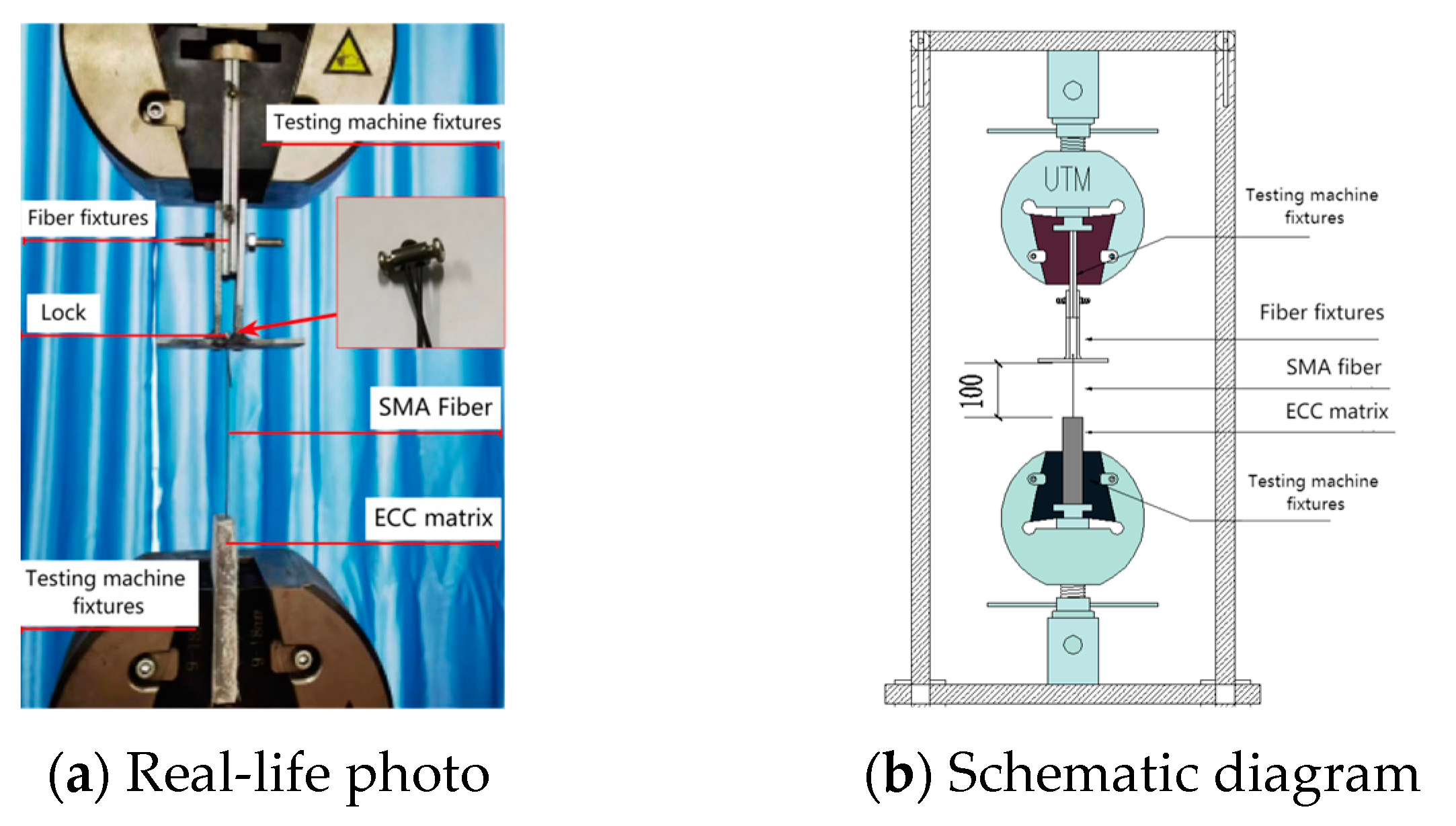
2.4. Pull-Out Mechanical Properties
3. Pull-Out Test Results
3.1. Failure Mode
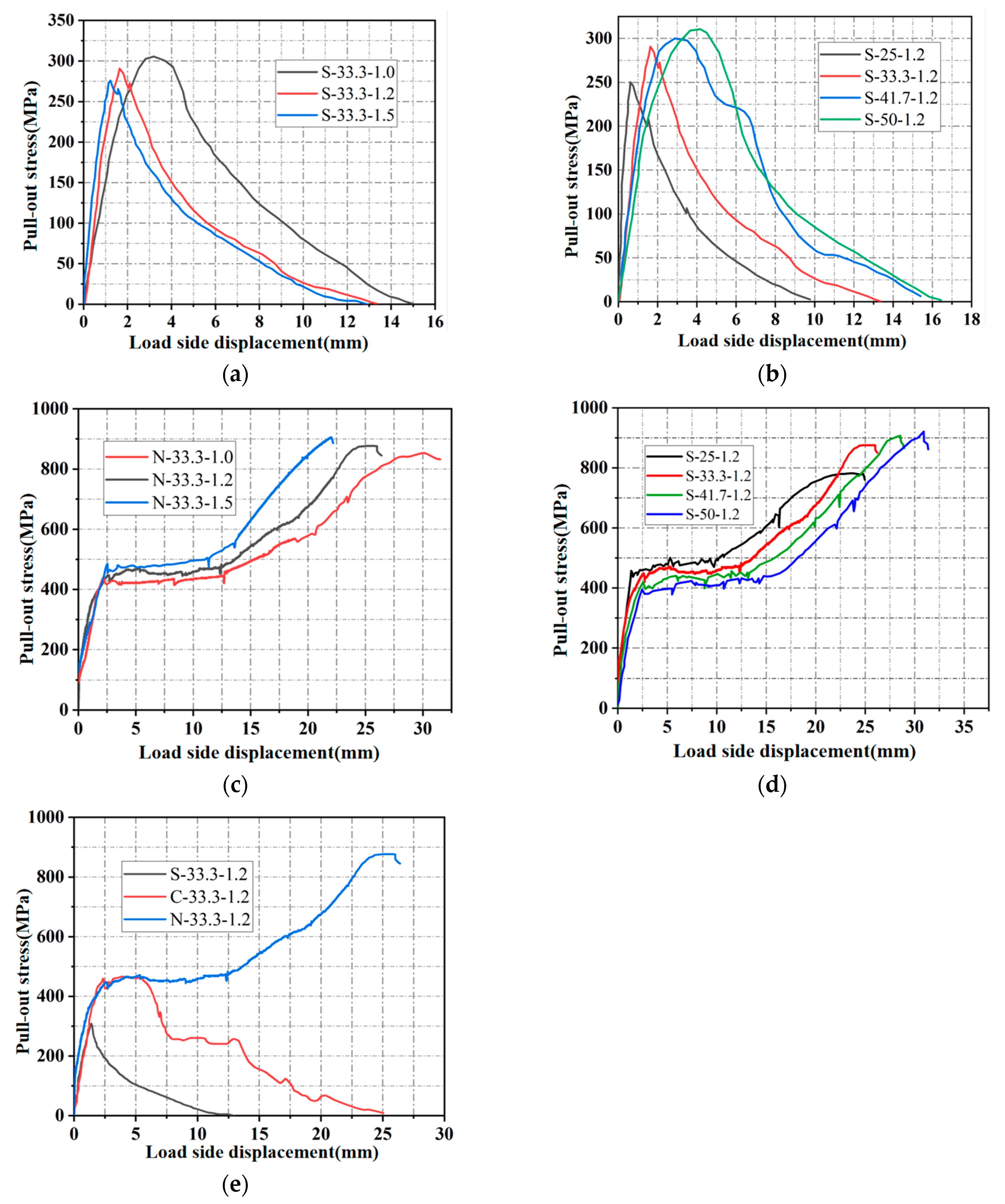
3.2. SMA Fiber Pull-Out Stress-Displacement Curve
4. The Bonding Mechanical Property Indexes and Influencing Factors
4.1. Calculation of the Bonding Mechanical Property Indexes
4.1.1. SMA Strength Utilization
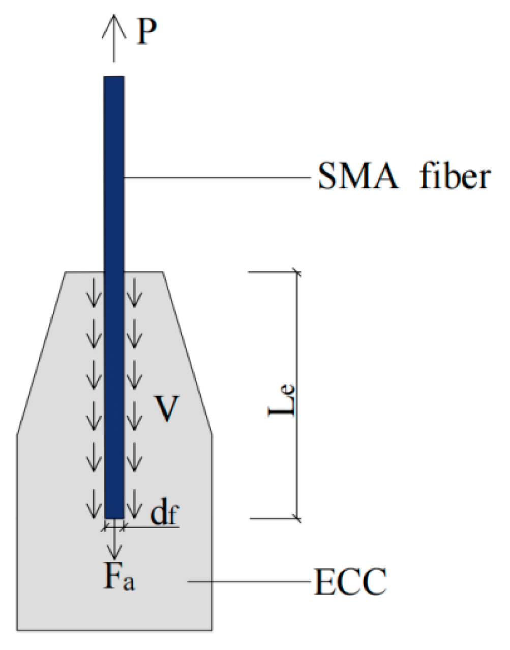
4.1.2. Anchorage Stress
4.1.3. SMA Strength Utilization
4.1.4. Calculation Results of the Bonding Mechanical Property Indexes
4.2. Influencing Factors of Bonding Mechanical Property Indexes
4.2.1. Straight-End SMA Fiber
- (1)
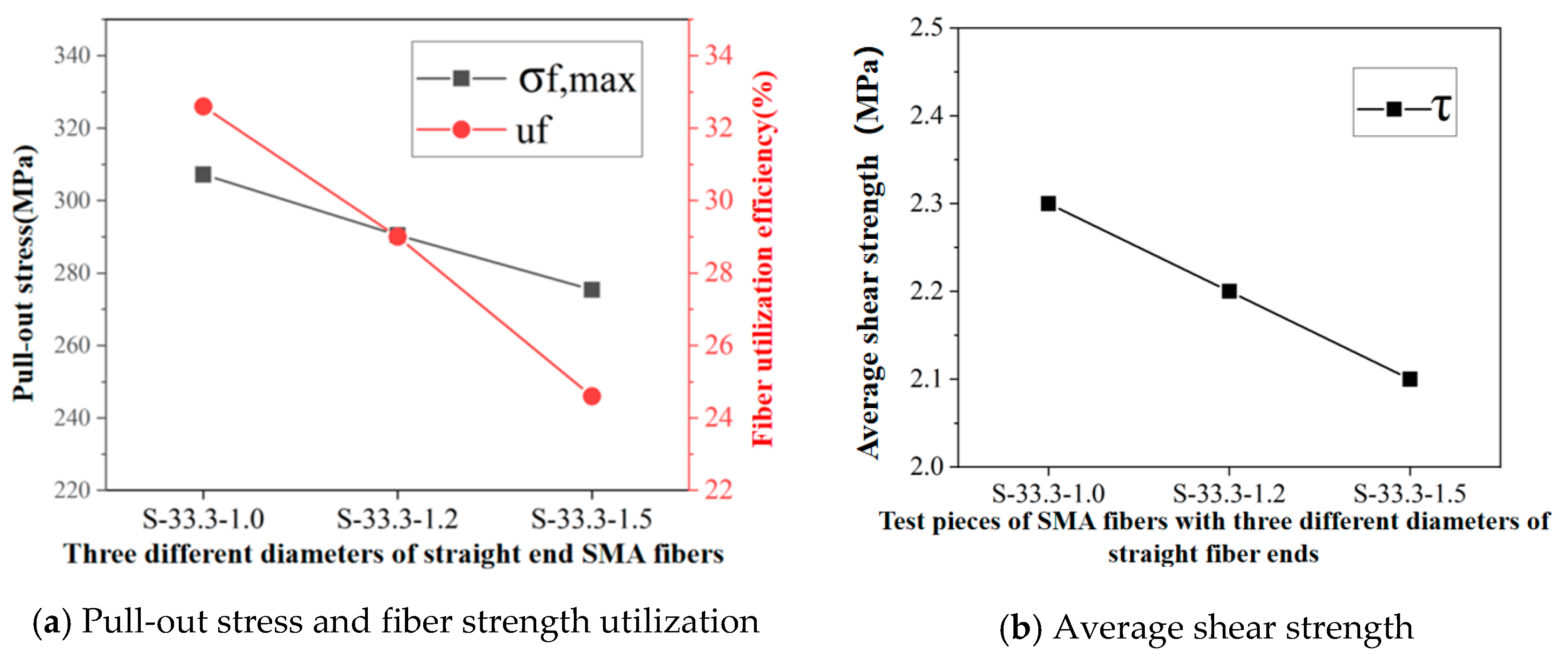
- Effect of diameter on the bonding mechanical properties
- (2)
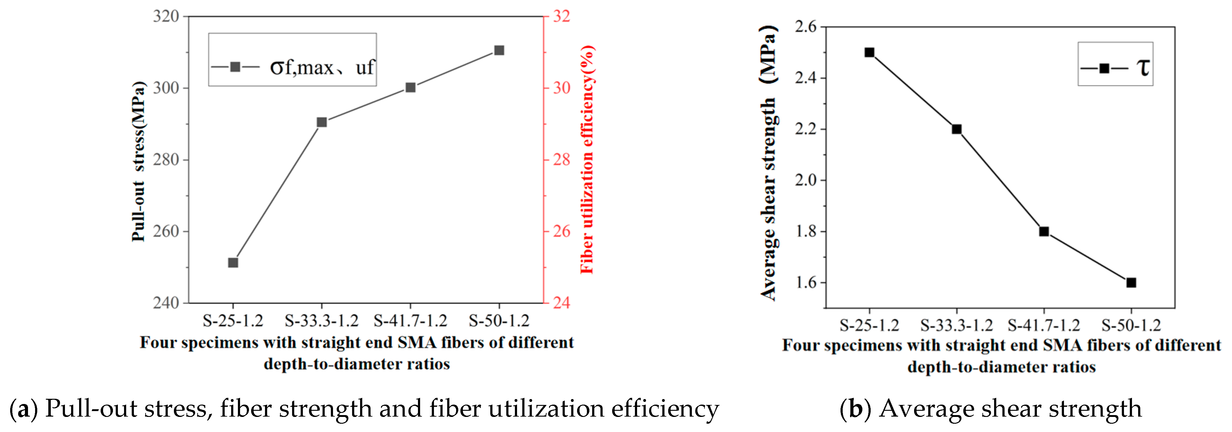
- Effect of depth-to-diameter ratio on the bonding mechanical properties
4.2.2. Non-Straight-End SMA Fiber
- (1)
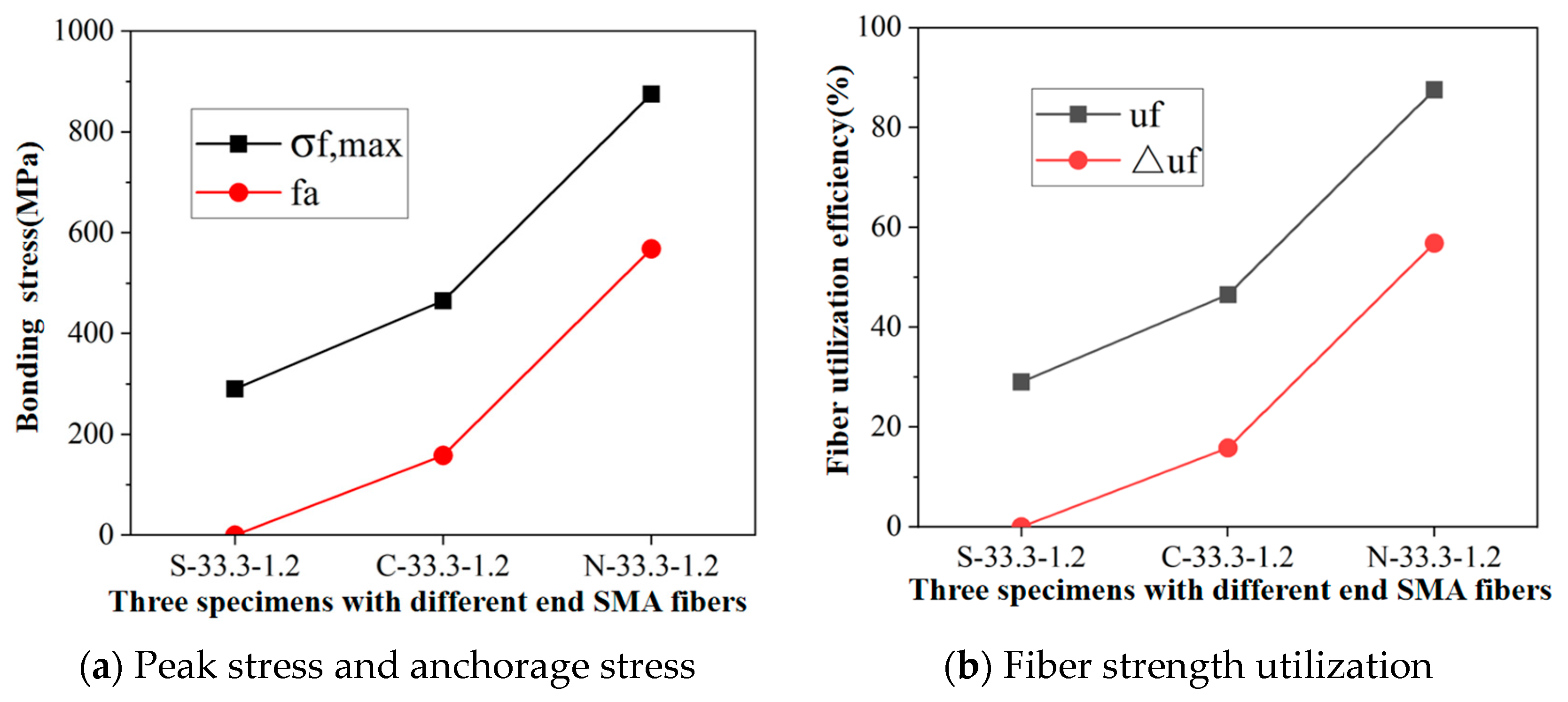
- Effect of end shape on the bonding mechanical properties
- (2)
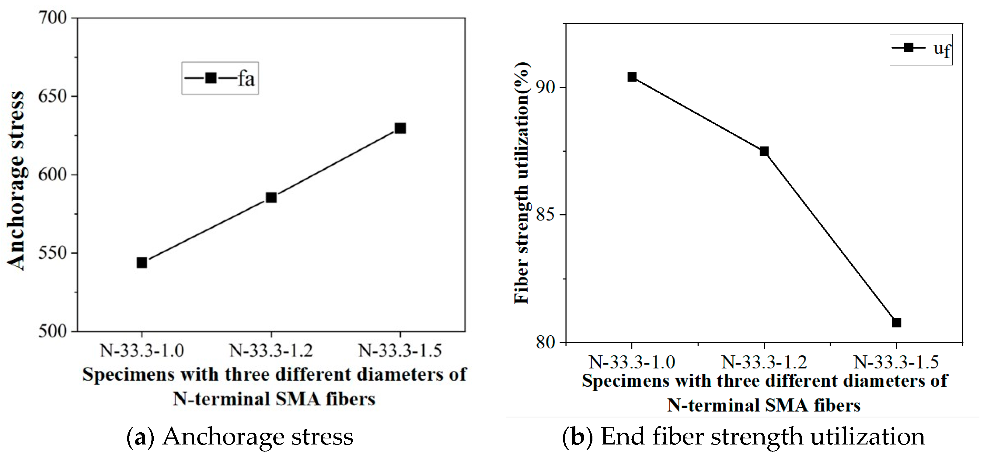
- Effect of fiber diameter on the bonding mechanical properties
- (3)
- Effect of depth-to-diameter ratio on the bonding mechanical properties
5. Conclusions
- The shear strength at the interface decreases as the depth-to-diameter ratio or diameter increases for SMA fibers with a straight end. The peak stress of SMA fibers with a straight end is 310.6 MPa, which is significantly lower than the stress level required for the martensitic transformation of SMA fibers. Consequently, the fibers do not undergo superelastic behavior, resulting in a low fiber utilization ratio.
- Compared to the straight-end fibers, the peak stress of SMA fibers with a curved end is higher, at 465.1 MPa, which can reach the stress level required for martensitic transformation. However, during the anchorage process, the stress concentration and deformation at the curved end leads to a continuous reduction in mechanical interlocking force and premature anchorage failure, thereby preventing the full development of superelasticity.
- The N-shaped end provides sufficient anchorage capacity for SMA fibers, significantly enhancing the bond strength between SMA fibers and the ECC matrix. The peak stress of SMA fibers can reach 875.9 MPa, which is 1.9 times and 3.0 times higher than that of curved-end and straight-end SMA fibers, respectively. This enables the stress in SMA fibers to reach the martensitic hardening stage until fiber fracture, thereby providing ample support for the full utilization of superelasticity in SMA fibers embedded in the ECC matrix.
- Under the full anchorage condition, as the fiber diameter increases, the anchorage stress at the N-shaped end increases and the enhanced fiber strength utilization decreases. With an increase in the depth-to-diameter ratio, both the anchorage stress and the enhanced fiber strength utilization initially increase and then stabilize. When the depth-to-diameter ratio is 41.7, the anchorage stress and the enhanced fiber strength utilization reach their maximum values, namely, 616.4 MPa and 61.6%, respectively.
Author Contributions
Funding
Data Availability Statement
Conflicts of Interest
References
- Grigorian, M.; Moghadam, A.S.; Mohammadi, H.; Kamizi, M. Methodology for developing earthquake-resilient structures. Struct. Des. Tall Spec. Build. 2019, 28, e1571. [Google Scholar] [CrossRef]
- Jia, M.; Gao, S.; Fu, F.; Yang, N. Failure mechanism and seismic performance evaluation of steel frame using rocking truss. Structures 2021, 33, 1180–1192. [Google Scholar] [CrossRef]
- You, T.; Wang, W.; Tesfamariam, S. Effects of self-centering structural systems on regional seismic resilience. Eng. Struct. 2023, 274, 115125. [Google Scholar] [CrossRef]
- Hu, H.; Liu, J.; Cheng, G.; Li, J.; Chen, Y.F. Seismic behavior of hybrid coupled wall system with replaceable endplate-steel coupling beam. J. Constr. Steel Res. 2021, 187, 106997. [Google Scholar] [CrossRef]
- Abavisani, I.; Rezaifar, O.; Kheyroddin, A. Multifunctional properties of shape memory materials in civil engineering applications: A state-of-the-art review. J. Build. Eng. 2021, 44, 102657. [Google Scholar] [CrossRef]
- Qian, H.; Fan, C.; Shi, Y.; Xu, J.; Li, Z.; Deng, E. Development and investigation of an innovative shape memory alloy cable-controlled self-centering viscoelastic coupling beam damper for seismic mitigation in coupled shear wall structures. Earthq. Eng. Struct. Dyn. 2023, 52, 370–393. [Google Scholar] [CrossRef]
- Jiang, Z.-Q.; Chen, M.-L.; Yang, Z.-S.; Li, X.-Y.; Cai, C. Cyclic loading tests of self-centering prestressed prefabricated steel beam-column joint with weakened FCP. Eng. Struct. 2022, 252, 113578. [Google Scholar] [CrossRef]
- Zhan, M.; Zhang, L.; Chen, X.; Wang, S.; Ma, Y. Experiment and Finite-Element Analysis on Seismic Response of Y-Shaped Porcelain Column Circuit Breaker Equipped with SMA Cables. Int. J. Civ. Eng. 2022, 20, 1211–1227. [Google Scholar] [CrossRef]
- Qiang, X.; Chen, L.; Jiang, X. Achievements and Perspectives on Fe-Based Shape Memory Alloys for Rehabilitation of Reinforced Concrete Bridges: An Overview. Materials 2022, 15, 8089. [Google Scholar] [CrossRef]
- Cortés-Puentes, W.L.; Palermo, D. SMA tension brace for retrofitting concrete shear walls. Eng. Struct. 2017, 140, 177–188. [Google Scholar] [CrossRef]
- Cortés-Puentes, L.; Zaidi, M.; Palermo, D.; Dragomirescu, E. Cyclic loading testing of repaired SMA and steel reinforced concrete shear walls. Eng. Struct. 2018, 168, 128–141. [Google Scholar] [CrossRef]
- Fakharifar, M.; Dalvand, A.; Arezoumandi, M.; Sharbatdar, M.K.; Chen, G.; Kheyroddin, A. Mechanical properties of high performance fiber reinforced cementitious composites. Constr. Build. Mater. 2014, 71, 510–520. [Google Scholar] [CrossRef]
- Ding, Y.; Yu, K.; Li, M. A review on high-strength engineered cementitious composites (HS-ECC): Design, mechanical property and structural application. Structures 2022, 35, 903–921. [Google Scholar] [CrossRef]
- Zhu, J.-X.; Xu, L.-Y.; Huang, B.-T.; Weng, K.-F.; Dai, J.-G. Recent developments in Engineered/Strain-Hardening Cementitious Composites (ECC/SHCC) with high and ultra-high strength. Constr. Build. Mater. 2022, 342, 127956. [Google Scholar] [CrossRef]
- Zhang, M.; Zhu, X.; Liu, B.; Shi, J.; Gencel, O.; Ozbakkaloglu, T. Mechanical property and durability of engineered cementitious composites (ECC) with nano-material and superabsorbent polymers. Powder Technol. 2022, 409, 117839. [Google Scholar] [CrossRef]
- Li, V.C. Applications of Engineered Cementitious Composites (ECC). In Engineered Cementitious Composites (ECC): Bendable Concrete for Sustainable and Resilient Infrastructure; Li, V.C., Ed.; Springer: Berlin/Heidelberg, Germany, 2019; pp. 313–369. [Google Scholar]
- Suryanto, B.; Tambusay, A.; Suprobo, P.; Bregoli, G.; Aitken, M. Seismic performance of exterior beam-column joints constructed with engineered cementitious composite: Comparison with ordinary and steel fibre reinforced concrete. Eng. Struct. 2022, 250, 113377. [Google Scholar] [CrossRef]
- Li, J.; Qiu, J.; Weng, J.; Yang, E.-H. Micromechanics of engineered cementitious composites (ECC): A critical review and new insights. Constr. Build. Mater. 2023, 362, 129765. [Google Scholar] [CrossRef]
- Yucel, H.E.; Dutkiewicz, M.; Yildizhan, F. Application of ECC as a Repair/Retrofit and Pavement/Bridge Deck Material for Sustainable Structures: A Review. Materials 2022, 15, 8752. [Google Scholar] [CrossRef]
- Qian, H.; Li, Z.; Pei, J.; Kang, L.; Li, H. Seismic performance of self-centering beam-column joints reinforced with superelastic shape memory alloy bars and engineering cementitious composites materials. Compos. Struct. 2022, 294, 115782. [Google Scholar] [CrossRef]
- Qian, H.; Ye, Y.; Yan, C.; Jin, G.; Li, C.; Shi, Y. Experimental study on the seismic performance of self-centering bridge piers incorporating ECC and superelastic SMA bars in the plastic hinge regions. Structures 2022, 46, 1955–1967. [Google Scholar] [CrossRef]
- Ali, M.A.E.M.; Soliman, A.M.; Nehdi, M.L. Hybrid-fiber reinforced engineered cementitious composite under tensile and impact loading. Mater. Des. 2017, 117, 139–149. [Google Scholar] [CrossRef]
- Lei, H.; Wang, Z.; Tong, L.; Zhou, B.; Fu, J. Experimental and numerical investigation on the macroscopic mechanical behavior of shape memory alloy hybrid composite with weak interface. Compos. Struct. 2013, 101, 301–312. [Google Scholar] [CrossRef]
- Shi, M.; Zhao, J.; Liu, J.; Wang, H.; Wang, Z.; Xu, L.; Sun, X. The Interface Adhesive Properties and Mechanical Properties of Shape Memory Alloy Composites. Fibers Polym. 2022, 23, 273–281. [Google Scholar] [CrossRef]
- Lau, K.-T.; Tam, W.-Y.; Meng, X.-L.; Zhou, L.-M. Morphological study on twisted NiTi wires for smart composite systems. Mater. Lett. 2002, 57, 364–368. [Google Scholar] [CrossRef]
- Smith, N.; Antoun, G.; Ellis, A.; Crone, W. Improved adhesion between nickel–titanium shape memory alloy and a polymer matrix via silane coupling agents. Compos. Part A Appl. Sci. Manuf. 2004, 35, 1307–1312. [Google Scholar] [CrossRef]
- Yuan, G.; Bai, Y.; Jia, Z.; Hui, D.; Lau, K.-T. Enhancement of interfacial bonding strength of SMA smart composites by using mechanical indented method. Compos. Part B Eng. 2016, 106, 99–106. [Google Scholar] [CrossRef]
- Choi, E.; Kim, D.; Lee, J.-H.; Ryu, G.-S. Monotonic and hysteretic pullout behavior of superelastic SMA fibers with different anchorages. Compos. Part B Eng. 2017, 108, 232–242. [Google Scholar] [CrossRef]
- Yang, Z.; Du, Y.; Liang, Y.; Ke, X. Mechanical Behavior of Shape Memory Alloy Fibers Embedded in Engineered Cementitious Composite Matrix under Cyclic Pullout Loads. Materials 2022, 15, 4531. [Google Scholar] [CrossRef]
- Yang, Z.; Gong, X.; Wu, Q.; Fan, L. Bonding Mechanical Properties between SMA Fiber and ECC Matrix under Direct Pullout Loads. Materials 2023, 16, 2672. [Google Scholar] [CrossRef]
- Zhou, X.; Ma, B.; Wei, K.; Wang, X. Deformation recovery properties of asphalt mixtures with shape memory epoxy resin. Constr. Build. Mater. 2021, 268, 121193. [Google Scholar] [CrossRef]
- Li, V.C.; Wang, S.; Wu, C. Tensile Strain-Hardening Behavior of Polyvinyl Alcohol Engineered Cementitious Composite (PVA-ECC). ACI Mater. J. 2001, 98, 483–492. [Google Scholar]
- JC/T 2461-2018; Standard Test Method for the Mechanical Properties of Ductile Fiber Reinforced Cementitious Composites. Ministry of Industry and Information Technology of People’s Republic of China: Beijing, China, 2018.
- Weimann, M.B.; Li, V.C. Hygral Behavior of Engineered Cementitious Composites (ECC)/Vergleich der hygrischen Eigenschaften von ECC mit Beton. Restor. Build. Monum. 2003, 9, 513–534. [Google Scholar] [CrossRef]
- Atli, K.; Karaman, I.; Noebe, R.; Garg, A.; Chumlyakov, Y.; Kireeva, I. Shape memory characteristics of Ti49.5Ni25Pd25Sc0.5 high-temperature shape memory alloy after severe plastic deformation. Acta Mater. 2011, 59, 4747–4760. [Google Scholar] [CrossRef]
- Kim, H.Y.; Jinguu, T.; Nam, T.H.; Miyazaki, S. Cold workability and shape memory properties of novel Ti-Ni-Hf-Nb high-temperature shape memory alloys. Scr. Mater. 2011, 65, 846–849. [Google Scholar] [CrossRef]
- Islam, S.; Afefy, H.M.; Sennah, K.; Azimi, H. Bond characteristics of straight and headed-end, ribbed-surface, GFRP bars embedded in high-strength concrete. Constr. Build. Mater. 2015, 83, 283–298. [Google Scholar] [CrossRef]
- Chen, S.M.; Li, H.H. Bond of Reinforcement in Ultra-High-Performance Concrete. Paper by Jiqiu Yuan and Benjamin Graybeal. ACI Struct. J. 2016, 113, 1130–1131. [Google Scholar]
- Ji, X.-D.; Cong, X.; Dai, X.-Q.; Zhang, A.; Chen, L.-H. Studying the mechanical properties of the soil-root interface using the pullout test method. J. Mt. Sci. 2018, 15, 882–893. [Google Scholar] [CrossRef]
- Maranan, G.; Manalo, A.; Karunasena, W.; Benmokrane, B. Pullout behaviour of GFRP bars with anchor head in geopolymer concrete. Compos. Struct. 2015, 132, 1113–1121. [Google Scholar] [CrossRef]
- Kim, M.K.; Kim, D.J.; Chung, Y.S.; Choi, E. Direct tensile behavior of shape-memory-alloy fiber-reinforced cement composites. Constr. Build. Mater. 2016, 102, 462–470. [Google Scholar] [CrossRef]
- Harajli, M.H. Bond Stress–Slip Model for Steel Bars in Unconfined or Steel, FRC, or FRP Confined Concrete under Cyclic Loading. J. Struct. Eng. 2009, 135, 509–518. [Google Scholar] [CrossRef]
- Ho, H.V.; Choi, E.; Park, S.J. Investigating stress distribution of crimped SMA fibers during pullout behavior using experimental testing and a finite element model. Compos. Struct. 2021, 272, 114254. [Google Scholar] [CrossRef]
- Abdallah, S.; Fan, M.; Cashell, K.A. Pull-out behaviour of straight and hooked-end steel fibres under elevated temperatures. Cem. Concr. Res. 2017, 95, 132–140. [Google Scholar] [CrossRef]
- Dehghani, A.; Aslani, F. Effect of 3D, 4D, and 5D hooked-end type and loading rate on the pull-out performance of shape memory alloy fibres embedded in cementitious composites. Constr. Build. Mater. 2021, 273, 121742. [Google Scholar] [CrossRef]
- Choi, E.; Mohammadzadeh, B.; Hwang, J.-H.; Kim, W.J. Pullout behavior of superelastic SMA fibers with various end-shapes embedded in cement mortar. Constr. Build. Mater. 2018, 167, 605–616. [Google Scholar] [CrossRef]


| Diameter (mm) | Elastic Modulus (GPa) | The Martensitic Phase Transition Begins/MPa | The Martensitic Phase Transition Ends/MPa | Peak Stress a (MPa) | Ultimate Strain b (%) | ||
|---|---|---|---|---|---|---|---|
| Strain (%) | Stress (MPa) | Strain (%) | Stress (MPa) | ||||
| 1.0 | 23.0 | 1.8 | 418.14 | 14.5 | 506.92 | 941.9 | 22.4 |
| 1.2 | 30.3 | 1.6 | 484.65 | 13.2 | 543.78 | 1001.1 | 21.8 |
| 1.5 | 34.0 | 1.5 | 509.89 | 12.9 | 652.51 | 1126.8 | 20.1 |
| Raw Materials | Cement | Fly Ash | Sand | Water | Water Reducer | PVA (%) * |
|---|---|---|---|---|---|---|
| Mix proportion | 1 | 4 | 0.2 | 0.22 | 0.0079 | 2 |
| Number | Initial Crack Strength (MPa) | Initial Fission Strain (%) | Tensile Modulus of Elasticity (GPa) | Peak Stress (MPa) | Ultimate Tensile Strain (%) |
|---|---|---|---|---|---|
| 1 | 2.43 | 0.27 | 9.0 | 5.12 | 5.24 |
| 2 | 2.74 | 0.19 | 11.3 | 4.78 | 5.95 |
| 3 | 2.59 | 0.32 | 8.1 | 4.33 | 5.32 |
| The average | 2.59 | 0.26 | 9.5 | 4.68 | 5.50 |
| Number | Number of Test Pieces | Specimen Number | End Shape | Depth-To-Diameter Ratio | Diameter/mm |
|---|---|---|---|---|---|
| 1 | 3 | S-33.3-1.0 | Straight | 33.3 | 1.0 |
| 3 | S-33.3-1.2 | 33.3 | 1.2 | ||
| 3 | S-33.3-1.5 | 33.3 | 1.5 | ||
| 2 | 3 | S-25-1.2 | Straight | 25 | 1.2 |
| 3 | S-33.3-1.2 | 33.3 | 1.2 | ||
| 3 | S-41.7-1.2 | 41.7 | 1.2 | ||
| 3 | S-50-1.2 | 50 | 1.2 | ||
| 3 | 3 | S-33.3-1.2 | Straight | 33.3 | 1.2 |
| 3 | C-33.3-1.2 | Curved | |||
| 3 | N-33.3-1.2 | N-end | |||
| 4 | 3 | N-33.3-1.0 | N-end | 33.3 | 1.0 |
| 3 | N-33.3-1.2 | 1.2 | |||
| 3 | N-33.3-1.5 | 1.5 | |||
| 5 | 3 | N-25-1.2 | N-end | 25 | 1.2 |
| 3 | N-33.3-1.2 | 33.3 | |||
| 3 | N-41.7-1.2 | 41.7 | |||
| 3 | N-50-1.2 | 50 |
| Group | Specimen Number | Pmax/N | /MPa | fy/MPa | σf,max/MPa | fa/MPa | uf/% | Δuf/% | Failure Mode |
|---|---|---|---|---|---|---|---|---|---|
| 1 | S-33.3-1.0 | 241.2 | 2.3 | 941.9 | 307.2 | ---- | 32.6 | ---- | Pull-out failure |
| S-33.3-1.2 | 328.4 | 2.2 | 1001.1 | 290.5 | ---- | 29.0 | ---- | Pull-out failure | |
| S-33.3-1.5 | 486.4 | 2.1 | 1120.4 | 275.4 | ---- | 24.6 | ---- | Pull-out failure | |
| 2 | S-25-1.2 | 284.1 | 2.5 | 1001.1 | 251.3 | ---- | 25.1 | ---- | Pull-out failure |
| S-33.3-1.2 | 328.4 | 2.2 | 1001.1 | 290.5 | ---- | 29.0 | ---- | Pull-out failure | |
| S-41.7-1.2 | 339.3 | 1.8 | 1001.1 | 300.2 | ---- | 30.0 | ---- | Pull-out failure | |
| S-50-1.2 | 351.1 | 1.6 | 1001.1 | 310.6 | ---- | 31.0 | ---- | Pull-out failure | |
| 3 | S-33.3-1.2 | 328.4 | 2.2 | 1001.1 | 290.5 | ---- | 29.0 | ---- | Pull-out failure |
| C-33.3-1.2 | 525.7 | ---- | 1001.1 | 465.1 | 174.6 | 46.5 | 17.4 | Pull-out failure | |
| N-33.3-1.2 | 990.1 | ---- | 1001.1 | 875.9 | 585.4 | 87.5 | 58.5 | Fracture failure | |
| 4 | N-33.3-1.0 | 668.1 | ---- | 941.9 | 851.1 | 543.9 | 90.4 | 57.7 | Fracture failure |
| N-33.3-1.2 | 990.1 | ---- | 1001.1 | 875.9 | 585.4 | 87.5 | 58.5 | Fracture failure | |
| N-33.3-1.5 | 1598.6 | ---- | 1120.4 | 905.1 | 629.7 | 80.8 | 56.2 | Splitting failure | |
| N-25-1.2 | 884.0 | ---- | 1001.1 | 782.2 | 491.7 | 78.1 | 49.1 | Splitting failure | |
| N-33.3-1.2 | 990.1 | ---- | 1001.1 | 875.9 | 585.4 | 87.5 | 58.5 | Fracture failure | |
| N-41.7-1.2 | 1025.2 | ---- | 1001.1 | 906.9 | 616.4 | 90.6 | 61.6 | Fracture failure | |
| N-50-1.2 | 1047.1 | ---- | 1001.1 | 926.3 | 615.7 | 92.5 | 61.5 | Fracture failure |
Disclaimer/Publisher’s Note: The statements, opinions and data contained in all publications are solely those of the individual author(s) and contributor(s) and not of MDPI and/or the editor(s). MDPI and/or the editor(s) disclaim responsibility for any injury to people or property resulting from any ideas, methods, instructions or products referred to in the content. |
© 2023 by the authors. Licensee MDPI, Basel, Switzerland. This article is an open access article distributed under the terms and conditions of the Creative Commons Attribution (CC BY) license (https://creativecommons.org/licenses/by/4.0/).
Share and Cite
Yang, Z.; Deng, T.; Fu, Q. The Effect of Fiber End on the Bonding Mechanical Properties between SMA Fibers and ECC Matrix. Buildings 2023, 13, 2027. https://doi.org/10.3390/buildings13082027
Yang Z, Deng T, Fu Q. The Effect of Fiber End on the Bonding Mechanical Properties between SMA Fibers and ECC Matrix. Buildings. 2023; 13(8):2027. https://doi.org/10.3390/buildings13082027
Chicago/Turabian StyleYang, Zhao, Tingyu Deng, and Qingshi Fu. 2023. "The Effect of Fiber End on the Bonding Mechanical Properties between SMA Fibers and ECC Matrix" Buildings 13, no. 8: 2027. https://doi.org/10.3390/buildings13082027