

A Simple Approach for the Dynamic Analysis of a Circular Tapered Pile under Axial Harmonic Vibration
Abstract
:1. Introduction
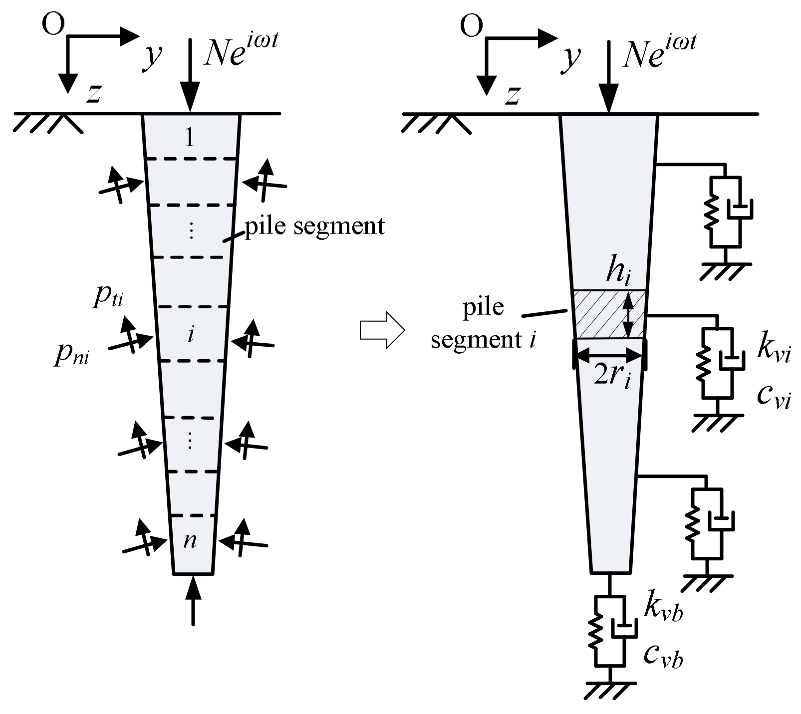
2. Physical Models
- (1)
- The tapered pile is elastic and perfectly bonded to the soil. The pile has a circular cross-section and is tapered along its shaft with a constant taper angle of θ.
- (2)
- The soil has m layers, and each layer is isotropic and homogeneous. Young’s modulus, density, damping ratio, and shear wave velocity of each soil layer are Esi, ρsi, βsi, and Vsi for the i-th section, respectively, and soil nonlinearity is neglected. The ground surface is free of normal and shear forces.
- (3)
- The tapered pile is subjected to a steady-state harmonic excitation with an amplitude Veiωt with frequency ω. There is no force or deformation out of the plane Oyz.
3. Formulation
4. Validation and Convergence Studies
4.1. Validation on Small Taper Angle Solution
4.2. Validation on Medium Taper Angle Solution
5. Results and Discussion
5.1. Effect of Pile Slenderness Ratio
5.2. Effect of Taper Angle
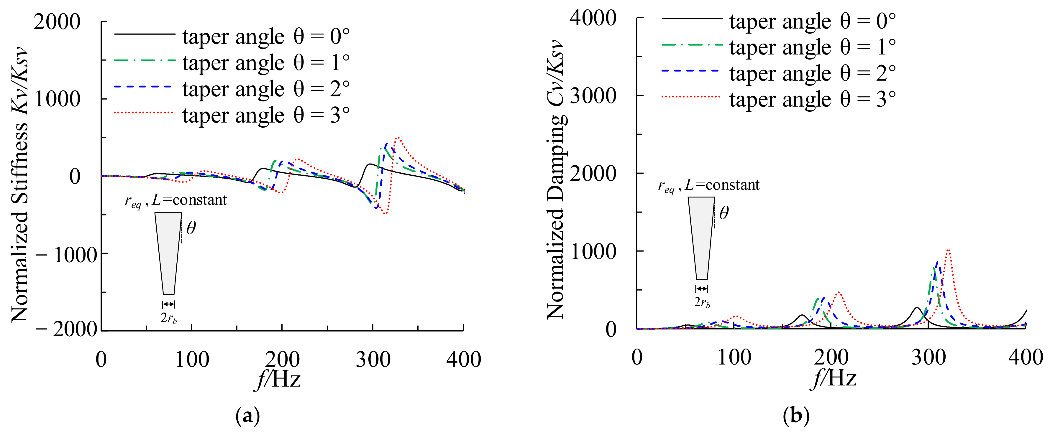
5.3. Discussion on Dynamic Impedance of Constant Volume Tapered Pile
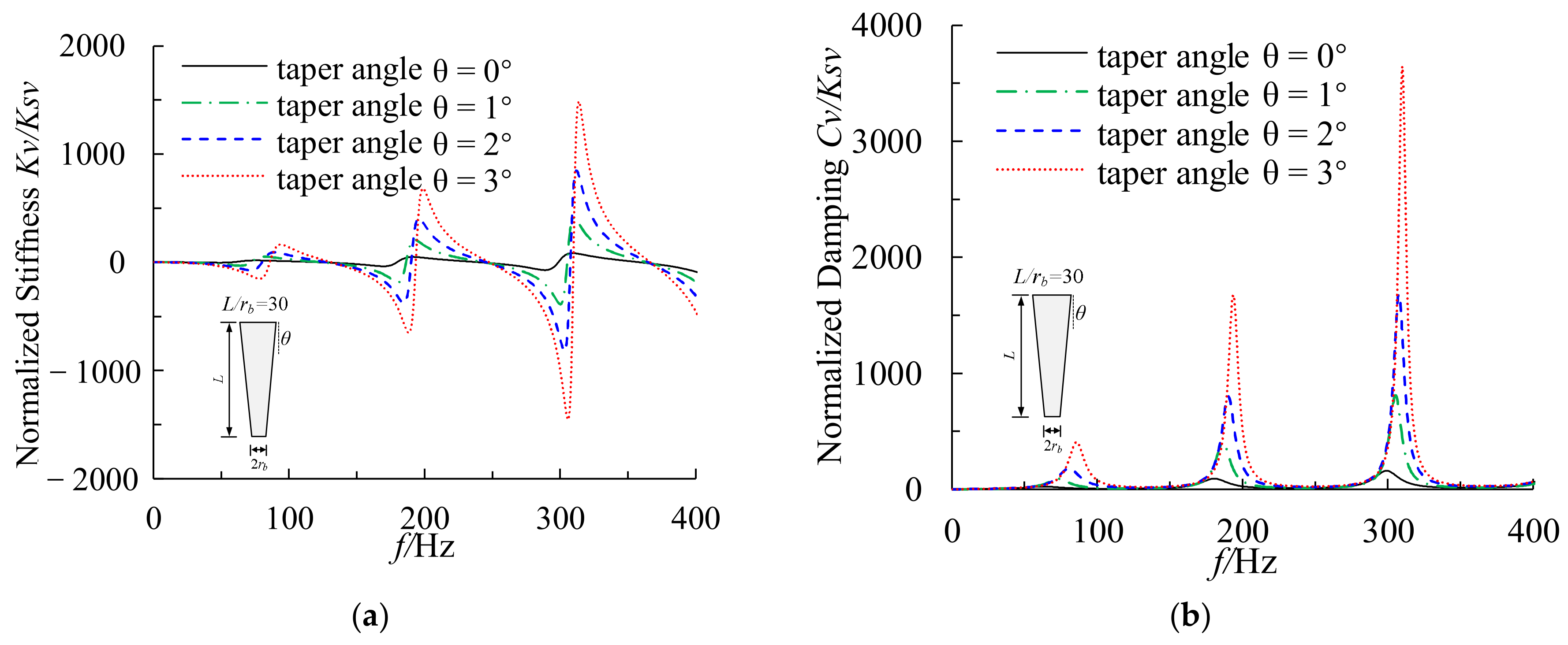
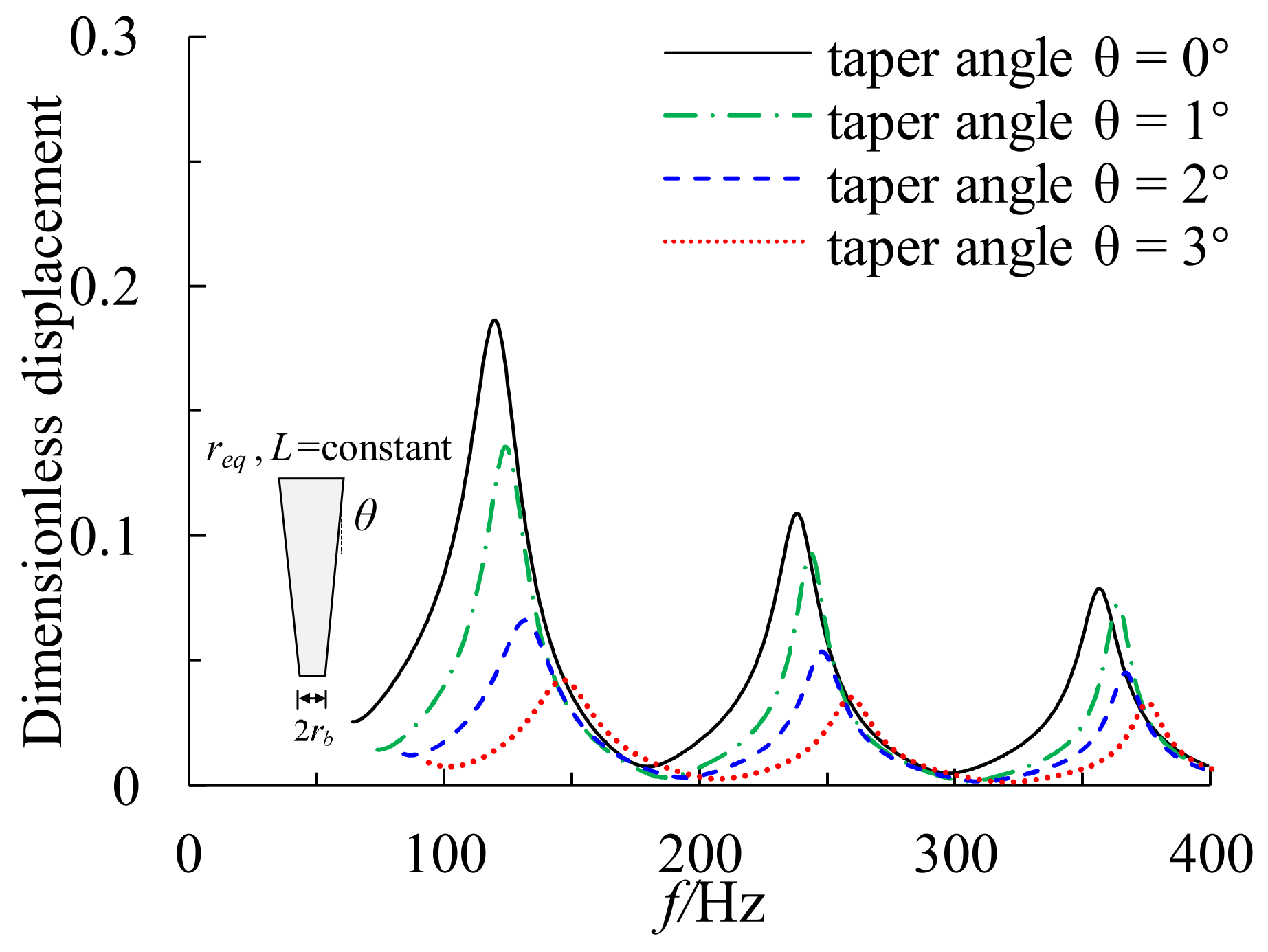
5.3.1. Varying Pile Tip Diameter with Constant Pile Length
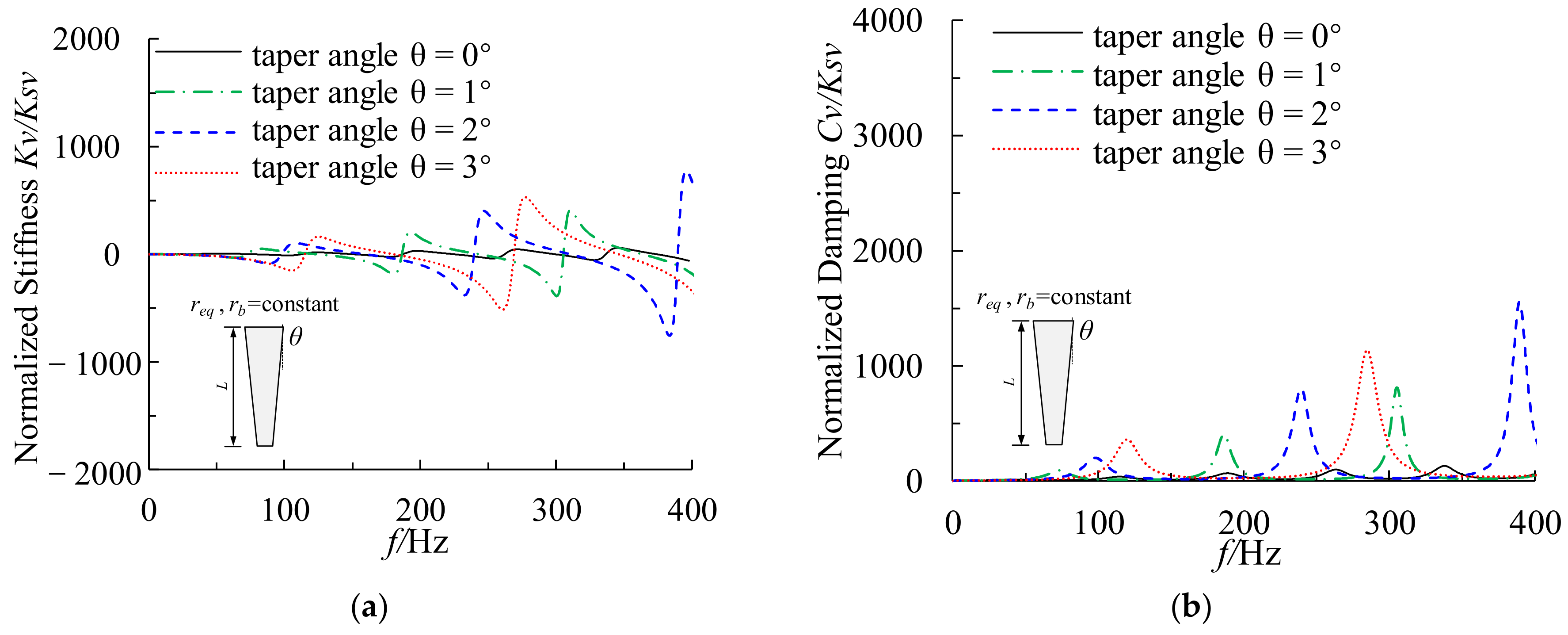
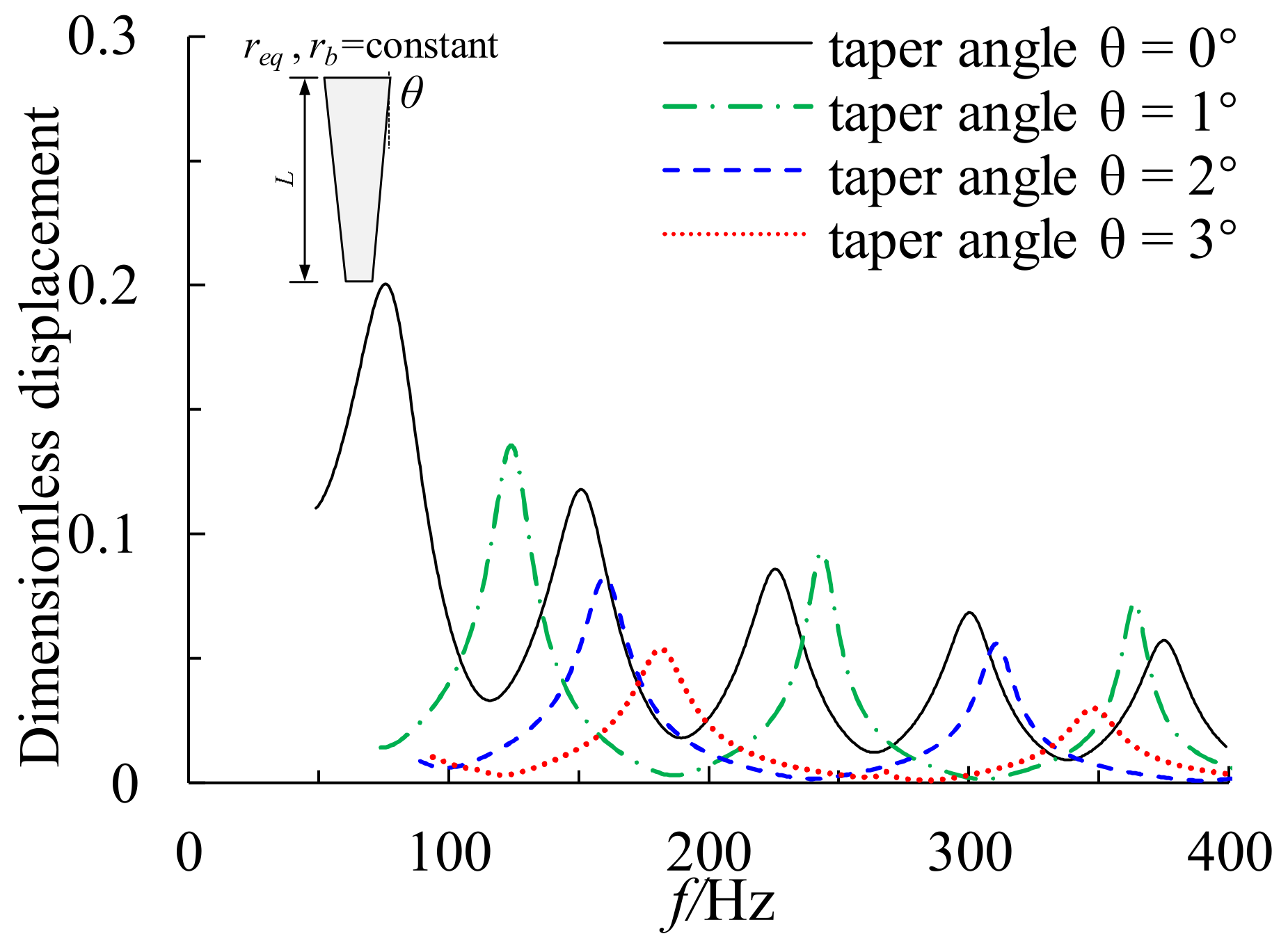
5.3.2. Varying Pile Tip Diameter with a Constant Pile Length
6. Conclusions
- (1)
- The proposed method retains high accuracy for calculating the vertical impedance function and dynamic response of tapered piles with different taper angles and slenderness ratios, while reducing the computational time and cost significantly.
- (2)
- The dynamic stiffness and damping of the tapered pile are significantly improved compared to the cylindrical pile with the same pile length and pile tip diameter, especially in the high-frequency range. In addition, the tapered pile exhibits better vibration performance than a cylindrical pile of the same volume.
- (3)
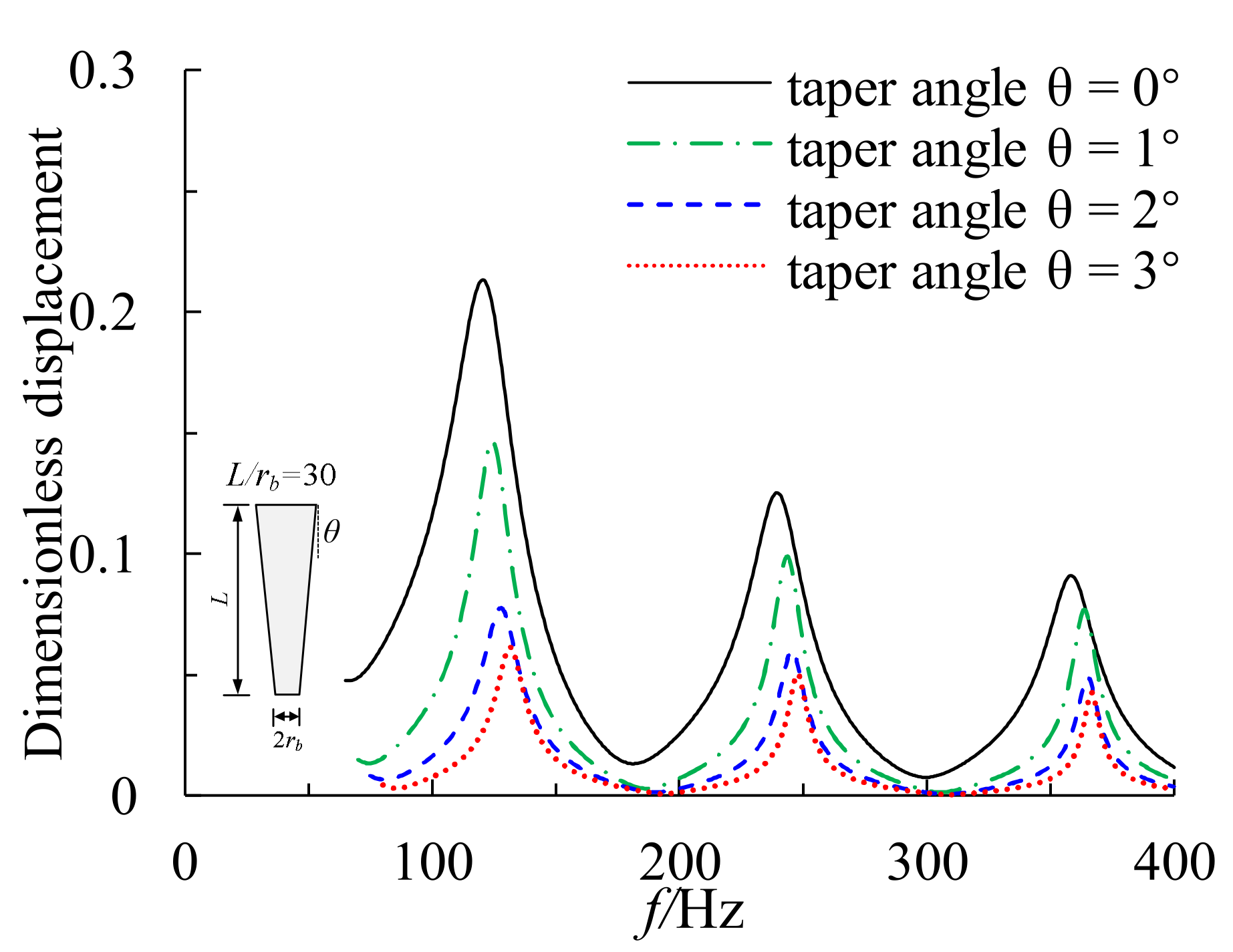
- The vertical dynamic impedance of the constant volume and constant length tapered pile increases as the taper angle increases. However, the increases in dynamic stiffness and damping are limited for taper angles larger than 1°. Meanwhile, the resonant amplitude decreases, and the resonant frequency increases for tapered piles with constant volume and length as the taper angle increases.
- (4)
- The vertical dynamic impedance and its oscillation period of a tapered pile with constant volume and constant tip diameter tapered pile increase significantly as the taper angle increases. The resonant frequency increases and the resonance amplitude decreases significantly as the taper angle increases. In addition, as the taper angle increases, the number of response resonant peaks within the concerned frequency range for high-speed railway subgrades decreases.
- (5)
- For fixed-volume tapered piles, keeping the tip diameter constant while varying pile length for different taper angles yields better vertical dynamic impedance than varying the tip diameter and keeping the pile length constant. However, the selected tapered pile length should also satisfy the subgrade settlement requirements. Since the method can be easily implemented, it presents an attractive and efficient tool to analyze and design tapered piles subjected to dynamic loading.
Author Contributions
Funding
Data Availability Statement
Conflicts of Interest
References
- Wei, J.Q.; El Naggar, M.H. Experimental study of axial behaviour of tapered piles. Can. Geotech. J. 1998, 35, 641–654. [Google Scholar] [CrossRef]
- Fellenius, B.H.; Altaee, A. Experimental study of axial behaviour of tapered piles: Discussion. Can. Geotech. J. 1999, 36, 1202. [Google Scholar] [CrossRef]
- Jiang, J.P.; Gao, G.Y.; Gu, B.H. Comparison of belled pile, tapered pile and equal-diameter pile. Chin. J. Geotech. Eng. 2003, 25, 764–766. (In Chinese) [Google Scholar]
- Hataf, N.; Shafaghat, A. Optimizing the bearing capacity of tapered piles in realistic scale using 3D finite element method. Geotech. Geol. Eng. 2005, 33, 1465–1473. [Google Scholar] [CrossRef]
- El Naggar, M.H.; Wei, J.Q. Axial capacity of tapered piles established from model tests. Can. Geotech. J. 1999, 36, 1185–1194. [Google Scholar] [CrossRef]
- Sakr, M.; El Naggar, M.H.; Nehdi, M. Lateral behaviour of composite tapered piles in dense sand. Proc. Inst. Civ. Eng. Geotech. Eng. 2005, 158, 145–157. [Google Scholar] [CrossRef]
- Kong, G.Q.; Peng, H.F.; Qin, H.Y.; Wang, L.H.; Meng, Y.D. Ultimate lateral bearing capacity and group effect of belled wedge pile groups. KSCE J. Civ. Eng. 2019, 23, 5041–5050. [Google Scholar] [CrossRef]
- Shafaghat, A.; Khabbaz, H. Recent advances and past discoveries on tapered pile foundations: A review. Geomech. Geoengin. 2022, 17, 455–484. [Google Scholar] [CrossRef]
- Min, C.Q.; Liu, J.; He, J.; Wang, Y.X. Research and application status of tapered Piles. Soil Eng. Found. 2009, 23, 73–76. (In Chinese) [Google Scholar]
- Tavenas, F.A. Load tests results on friction piles in sand. Can. Geotech. J. 1971, 8, 7–22. [Google Scholar] [CrossRef]
- Ismael, N.F. Behavior of step tapered bored piles in sand under static lateral loading. J. Geotech. Geoenviron. Eng. 2010, 136, 669–676. [Google Scholar] [CrossRef]
- Liu, J.; He, J.; Wu, Y.P.; Yang, Q.C. Load transfer behaviour of a tapered rigid pile. Géotechnique 2012, 62, 649–652. [Google Scholar] [CrossRef]
- Hataf, N.; Shafaghat, A. Numerical comparison of bearing capacity of tapered pile groups using 3D FEM. Geomech. Eng. 2015, 9, 547–567. [Google Scholar] [CrossRef]
- Fang, T.; Huang, M. Deformation and load-bearing characteristics of step-tapered piles in clay under lateral load. Int. J. Geomech. 2019, 19, 04019053. [Google Scholar] [CrossRef]
- Liu, X.; Wu, W.; El Naggar, M.H.; Wang, K.; Mei, G.; Liu, H.; Wang, L.; Sun, J. A simplified non-axisymmetric pile-soil interaction model for pile integrity testing analysis. Appl. Math. Model. 2023, 119, 137–155. [Google Scholar] [CrossRef]
- El Naggar, M.H.; Wei, J.Q. Cyclic response of axially loaded tapered piles. Geotech. Test. J. 2000, 23, 100–115. [Google Scholar]
- El Naggar, M.H.; Sakr, M. Cyclic response of axially loaded tapered piles. Int. J. Phys. Model. Geotech. 2002, 2, 1–12. [Google Scholar]
- Fahmy, A.; El Naggar, M.H. Cyclic lateral performance of helical tapered piles in silty sand. DFI J. J. Deep. Found. Inst. 2016, 10, 111–124. [Google Scholar] [CrossRef]
- Tavasoli, O.; Ghazavi, M. Effect of tapered and semi-tapered geometry on the offshore piles driving performance. Ocean Eng. 2020, 201, 107147. [Google Scholar] [CrossRef]
- Ghazavi, M. Response of tapered piles to axial harmonic loading. Can. Geotech. J. 2008, 45, 1622–1628. [Google Scholar] [CrossRef]
- Saha, S.; Ghosh, D.P. Vertical vibration of tapered piles. J. Geotech. Eng. 1986, 112, 290–302. [Google Scholar] [CrossRef]
- Xie, J.; Vaziri, H.H. Vertical vibration of nonuniform piles. J. Eng. Mech. 1991, 117, 1105–1118. [Google Scholar] [CrossRef]
- Gao, L.; Wang, K.; Xiao, S.; Wu, J.; Wang, N. Vertical impedance of tapered piles considering the vertical reaction of surrounding soil and construction disturbance. Mar. Geores. Geotechnol. 2017, 35, 1068–1076. [Google Scholar] [CrossRef]
- Bryden, C.; Arjomandi, K.; Valsangkar, A. Dynamic axial stiffness and damping parameters of tapered piles. Int. J. Geomech. 2018, 18, 06018014. [Google Scholar] [CrossRef]
- Singh, S.; Patra, N.R. Axial dynamic response of concrete-filled tapered fiber reinforced polymer piles in a transversely isotropic medium. Comput. Geotech. 2020, 123, 103557. [Google Scholar] [CrossRef]
- Cai, Y.Y.; Yu, J.; Zheng, C.T.; Qi, Z.B.; Song, B.X. Analytical solution for longitudinal dynamic complex impedance of tapered pile. Chin. J. Geotech. Eng. 2011, 33, 392–398. (In Chinese) [Google Scholar]
- Wu, Z.M.; Huang, M.S.; Ren, Q. Vertical vibration and internal forces of pile groups in layered soil. J. Tongji Univ. 2007, 35, 21–26. (In Chinese) [Google Scholar]
- Dehghanpoor, A.; Ghazavi, M. Response of tapered piles under lateral harmonic vibrations. Int. J. Geomach. 2012, 2, 261–265. [Google Scholar] [CrossRef]
- Wang, J.; Zhou, D.; Zhang, Y.; Cai, W. Vertical impedance of a tapered pile in inhomogeneous saturated soil described by fractional viscoelastic model. Appl. Math. Model. 2019, 75, 88–100. [Google Scholar] [CrossRef]
- Guan, W.; Wu, W.; Jiang, G.; Chin, J.; Deng, G. Torsional dynamic response of tapered pile considering compaction effect and stress diffusion effect. J. Cent. South Univ. Technol. 2020, 27, 3839–3851. [Google Scholar] [CrossRef]
- Tu, W.B.; Huang, M.S.; Gu, X.Q.; Chen, H.P. Nonlinear dynamic behavior of laterally loaded composite caisson-piles foundation under scour conditions. Mar. Geores. Geotechnol. 2020, 38, 1265–1280. [Google Scholar] [CrossRef]
- Zhang, H.; Liang, F.Y.; Zheng, H.B. Dynamic impedance of monopiles for offshore wind turbines considering scour-hole dimensions. Appl. Ocean Res. 2021, 107, 102493. [Google Scholar] [CrossRef]
- Zhang, Y.P.; Di, T.Y.; El Naggar, M.H.; Wu, W.B.; Liu, H.; Jiang, G.S. Modified Rayleigh-Love rod model for 3D dynamic analysis of large-diameter thin-walled pipe pile embedded in multilayered soils. Comput. Geotech. 2022, 149, 104853. [Google Scholar] [CrossRef]
- Gazetas, G.; Makris, N. Dynamic pile-soil-pile interaction. Part I: Analysis of axial vibration. Earthq. Eng. Struct. Dyn. 1991, 20, 115–132. [Google Scholar] [CrossRef]
- Liu, H.; Wu, W.; Yang, X.; Liu, X.; Wang, L.; El Naggar, M.H.; Wen, M. Apparent wave velocity inverse analysis method and its application in dynamic pile testing. Int. J. Numer. Anal. Met. 2022, 47, 549–569. [Google Scholar] [CrossRef]
- Nogami, T.; Novák, M. Soil-pile interaction in vertical vibration. Earthq. Eng. Struct. Dyn. 1976, 4, 277–293. [Google Scholar] [CrossRef]
- Kuhlemeyer, R.L. Vertical vibration of piles. J. Geotech. Eng. Div. 1978, 105, 273–287. [Google Scholar] [CrossRef]
- Wu, W.; Wang, Z.; Zhang, Y.; El Naggar, M.H.; Wu, T.; Wen, M. Semi-analytical solution for negative skin friction development on deep foundations in coastal reclamation areas. Int. J. Mech. Sci. 2023, 241, 107981. [Google Scholar] [CrossRef]
- Makris, N.; Gazetas, G. Dynamic pile-soil-pile interaction. Part II: Lateral and seismic response. Earthq. Eng. Struct. Dyn. 1992, 21, 145–162. [Google Scholar] [CrossRef]
- Mylonakis, G.; Gazetas, G. Vertical vibration and additional distress of grouped piles in layered soil. Soils Found. 1998, 38, 1–14. [Google Scholar] [CrossRef] [Green Version]
- Lysmer, J.F.E.R.; Richart, F.E., Jr. Dynamic response of footings to vertical loading. J. Soil Mech. Found. Div. 1966, 92, 65–91. [Google Scholar] [CrossRef]
- Kaynia, A.M. Dynamic Stiffness and Seismic Response of Pile Groups. Ph.D. Thesis, Massachusetts Institute of Technology, Cambridge, MA, USA, 1982. [Google Scholar]
- Feng, S.J.; Zhang, X.L.; Zheng, Q.T.; Wang, L. Simulation and mitigation analysis of ground vibrations induced by high-speed train with three dimensional FEM. Soil Dyn. Earthq. Eng. 2017, 94, 204–214. [Google Scholar] [CrossRef]
- Thomson, W.T. Theory of Vibration with Applications; CRC Press: Boca Raton, FL, USA, 2018. [Google Scholar]
- Wu, W.B.; Wang, K.H.; Dou, B. Vertical dynamic response of a viscoelastic tapered pile embedded in layered foundation. J. Vib. Shock 2013, 32, 120–127. (In Chinese) [Google Scholar]
- Ghazavi, M. Analysis of kinematic seismic response of tapered piles. Geotech. Geol. Eng. 2007, 25, 37–44. [Google Scholar] [CrossRef]


| Material Property | Value | |
|---|---|---|
| Pile | Equivalent radius req | 0.1 m |
| Pile length L | 5 m | |
| Taper angle θ | 1.5° | |
| Elastic modulus Ep | 20 GPa | |
| Density ρp | 2400 kg/m3 | |
| Soil | Elastic modulus Es | 30.6 MPa |
| Density ρs | 1800 kg/m3 | |
| Shear wave velocity Vs | 82.5m/s | |
| Poisson’s ratio νs | 0.25 |
Disclaimer/Publisher’s Note: The statements, opinions and data contained in all publications are solely those of the individual author(s) and contributor(s) and not of MDPI and/or the editor(s). MDPI and/or the editor(s) disclaim responsibility for any injury to people or property resulting from any ideas, methods, instructions or products referred to in the content. |
© 2023 by the authors. Licensee MDPI, Basel, Switzerland. This article is an open access article distributed under the terms and conditions of the Creative Commons Attribution (CC BY) license (https://creativecommons.org/licenses/by/4.0/).
Share and Cite
Hu, J.; Tu, W.; Gu, X. A Simple Approach for the Dynamic Analysis of a Circular Tapered Pile under Axial Harmonic Vibration. Buildings 2023, 13, 999. https://doi.org/10.3390/buildings13040999
Hu J, Tu W, Gu X. A Simple Approach for the Dynamic Analysis of a Circular Tapered Pile under Axial Harmonic Vibration. Buildings. 2023; 13(4):999. https://doi.org/10.3390/buildings13040999
Chicago/Turabian StyleHu, Jing, Wenbo Tu, and Xiaoqiang Gu. 2023. "A Simple Approach for the Dynamic Analysis of a Circular Tapered Pile under Axial Harmonic Vibration" Buildings 13, no. 4: 999. https://doi.org/10.3390/buildings13040999