Article

Finite Element Analysis of Shear Reinforcing of Reinforced Concrete Beams with Carbon Fiber Reinforced Polymer Grid-Strengthened Engineering Cementitious Composite

by
Mohammadsina Sharifi Ghalehnoei
1,*,
Ahad Javanmardi
2,*,
Mohammadreza Izadifar
3,
Neven Ukrainczyk
3 and
Eduardus Koenders
3
1
Department of Civil Engineering, University of Esfahan, Esfahan 8174673441, Iran
2
College of Civil Engineering, Fuzhou University, University Town, 2 Xueyuan Road, Fuzhou 350108, China
3
Institute of Construction and Building Materials, Technical University of Darmstadt, Franziska-Braun-Str. 3, 64287 Darmstadt, Germany
*
Authors to whom correspondence should be addressed.
Buildings 2023, 13(4), 1034; https://doi.org/10.3390/buildings13041034
Submission received: 14 December 2022 / Revised: 2 April 2023 / Accepted: 11 April 2023 / Published: 14 April 2023

Abstract

:
This study investigates the shear behavior of reinforced concrete (RC) beams that have been strengthened using carbon fiber reinforced polymer (CFRP) grids with engineered cementitious composite (ECC) through finite element (FE) analysis. The analysis includes twelve simply supported and continuous beams strengthened with different parameters such as CFRP sheets, CFRP grid cross-sectional area, and CFRP grid size. To conduct the analysis, FE models of the RC beams were created and analyzed using ABAQUS software. Research results show that the strengthened RC beams with CFRP grids and ECC had approx. 30–50% higher shear capacity than reference RC beams. The composite action of CFRP grids with the ECCs also showed a significant ability to limit diagonal cracks and prevent the degradation of the bending stiffness of the RC beams. Furthermore, this study calculated the shear capacity of the strengthened beams using an analytical model and compared it with the numerical analysis results. The analytical equations showed only a 4% difference from the numerical results, indicating that the analytical model can be used in practice.

1. Introduction

The deterioration of reinforced concrete (RC) structures has become increasingly severe in recent years [1,2] The deterioration not only compromises the serviceability of the structure but also poses serious safety risks for humans [3,4,5]. Corrosion, overload, fatigue, and other negative conditions have a direct impact on the performance of RC structures. Under extreme circumstances, traditional RC beams may be prone to damage and collapse, resulting in significant financial losses. Retrofitting damaged or strengthening weak RC structures with shear defects has become a major challenge in the construction sector [6,7,8,9], as it is crucial to enhance the durability and safety of these structures. As a result, developing techniques for strengthening damaged structures to increase the sustainability and durability of existing RC structures is of great practical and scientific importance [10]. In recent years, the application of Fiber-Reinforced Polymer (FRP) for repairing, strengthening, and retrofitting RC structural elements such as beams and columns has been increased [7,11,12,13,14,15,16,17] due to its lightweight, high-strength, strong corrosion resistance, and high-durability features. Bonding FRP laminates with adhesive to concrete surfaces is a common solution for external strengthening. An adhesive such as epoxy resin serves as a connector at the interface between the concrete surfaces and FRP laminates that transfers stress to the FRP laminates.
Shear strengthening of RC beams can be achieved by using different materials and methods. In recent decades, a great deal of attention has been paid to the shear strengthening of RC beams using FRP materials by either wrapping FRP or attaching the CFRP to the side of beams using adhesives such as epoxy resin [18,19,20,21,22]. However, epoxy resin has a few drawbacks including poor fire resistance, low glass transition temperature (Tg), sensitivity to UV radiation, and quick degradation in wet environments [6,23]. To overcome these shortcomings, the carbon-FRP (CFRP) grid with different cementitious materials such as UHPC for RC structures is a new strengthening method [6,24,25,26]. For example, the FRP grid improves the ultimate loading capacity and ultimate tensile capacity of the UHPC beams [24]. The FRP grid also enhances the shear and ductility of the UHPC beams [26].
Generally, several factors affect the shear strengthening of RC beams using FRP materials, as listed in Table 1. The failure mode of RC beams strengthened by FRP sheets is generally debonding, while BFRP grids prevent premature debonding failure at the interface of the concrete [6]. Meanwhile, the epoxy resin provides better bond performance at the interface of the BFRP gird with the concrete as compared with PCM. Azam et al.’s [27] comparative study concluded that the CFRP grid with cement-based mortar was slightly more effective than the CFRP sheets with epoxy resin in the shear strengthening of RC beams. Moreover, the grid size of the CFRP significantly influences the shear strength of the RC beams [28]. Guo et al. [29] investigated the application of CFRP grids with polymer-cement-mortar (PCM) shotcrete for the shear strengthening of RC beams. The shear capacity of the beam strengthened by the CFRP grids was 30–40% larger than that of the PCM-reinforced and unreinforced beams. Therefore, the effect of PCM shotcrete on the shear strength was insignificant and the CFRP grid sufficiently improved the shear capacity of the beam. Generally, the CFRP grids primarily contributed to improving the shear strength [30]. Cai et al. [31] used CFRP grids with epoxy mortar to improve the shear behavior of RC beams. The study results showed that the shear capacity of the RC beams increased up to 56%. The vertical grids of CFRP primarily contributed to the shear capacity improvement while the horizontal grids controlled the crack propagation and improved the bond behavior. Nevertheless, the RC beams strengthened with smaller grid dimensions have a better shear performance than the beams strengthened with larger grid dimensions [29]. In addition, the shear strength depends on the concrete strength and the shear span ratio of the beam [6,29]. Chen et al. [32] used CFRP meshes with UHPC for shear strengthening of corroded RC beams. The composite action between the CFRP and UHPC layer was very strong as there was no debonding during the loading test. The experimental results showed that this method substantially improves the shear capacity and crack resistance of the corroded RC beams. Nevertheless, increasing the number of layers does not necessarily increase the shear strength of the beam but leads to better ductile behavior [32].
In recent years, a new composite material named Engineered Cementitious Composite (ECC) has been developed by the mixing of cement, fine sand, other admixtures, and shortcut fibers randomly distributed in the matrix. The ECC has excellent tensile strength, high ductility, toughness performance, and durability. Studies on the mechanical properties of ECC showed that the ultimate tensile strain of ECC is much greater than 2%, which is about 200 times larger than normal concrete [33,34,35,36]. Further, the ultimate compressive strain of the ECC is twice larger than normal concrete. Meanwhile, the compressive strength of ECC is similar to normal concrete; however, the elastic modulus of ECC is about half of that of normal concrete because of the absence of coarse aggregates. Therefore, the ECC as a shear-strengthening material for RC beams is ineffective or has very low efficiency as compared with other methods.
Given the fact that FRP grids are able to improve the shear capacity of the RC beams, and to take the advantage of features of ECC, a new composite material was proposed in this study for the shear strengthening of RC beams. In this method, FRP grids were attached on both sides, and the soffit of the RC beam was within layers of ECC, as shown in Figure 1. The ECC layers have two purposes: (i) to make a much stronger bond between the FRP grids to the substrate concrete, and (ii) to strengthen the RC beam. For this purpose, a simply supported beam and a continuous RC beam were selected from the literature [37] for shear strengthening through numerical analysis. The selected RC beams were modeled with ABAQUS Finite Element (FE) software [38]. The models were then analyzed and validated with the results of the experiments [37]. Thereafter, the effectiveness of CFRP grids with ECC for shear strengthening of the RC beams was studied using the validated models. Further, the effect of different parameters including CFRP grid size, and CFRP grid cross-sectional area were studied and compared with the reference beams and beams strengthened with CFRP sheets. Lastly, calculation formulae for the shear capacity of the RC beam strengthened with the proposed composite material were given and compared with the numerical analysis.

2. Methodology

2.1. Experimental Study [37]

Pellegrino and Modena [37] investigated the shear behavior of RC beams strengthened with CFRP wraps. In total, 12 RC beams were tested in the laboratory including 3 reference beams and 8 beams with externally bonded U-wrapped CFRP. The CFRP was wrapped on both sides and the soffit of the beams. Figure 2 shows the detailed dimensions of the beams, steel reinforcements, and stirrups as well as the location of loads and supports. Four steel bars of 30 mm diameter were used for the tensile and compressive reinforcement of the beam. Steel bars of 8 mm diameter were used for stirrups with a spacing of 170 mm for both types of beams, as illustrated in Figure 2c. As shown in Figure 2, two configurations, i.e., a simply supported beam (Figure 2b) and a continuous beam (Figure 2a) were considered for shear testing of the beams in order to maximize the shear and bending moment acting at support. In other words, the beams were designed to fail due to shear before flexural failure. A 500 kN hydraulic jack was used for the three- or four-point flexural tests. Two strain gauges were installed on the beams in vertical and horizontal directions and one strain gauge was installed at a 45-degree inclination with respect to the horizontal direction, as shown in Figure 2a,b. More details of the experimental work can be found in the reference [37]. In the current study, eight of the twelve beams with the details shown in Table 2 were selected for FE modeling, validation, and further comparisons. These beams were further used for strengthening by the CFRP grid with ECC.

2.2. Beams’ Details

In this research, a total of 12 RC beams were used for shear behavior investigations, as listed in Table 3. Two of these beams, namely, A-C-17 and A-S-17 were the reference beams, which had the same detailing as the experimental work (see Table 2). Two beams, namely, CR-C-17 and CR-S-17 were strengthened with CFRP sheets, which also had the same detailing as the experimental work (see Table 2). For shear strengthening of RC beams using CFRP grids with ECC, two parameters, i.e., CFRP grid size and cross-sectional area of CFRP grids were considered, as shown in Table 3. The procedure for strengthening the RC beams using the CFRP grid with ECC is as follows: (i) after cleaning the surface of the RC beams from the dirt and dust, a 10 mm thick layer of ECC was applied to the surface of the concrete; (ii) then, the CFRP grid was cut based on the dimension of the beam and placed on the beam; and (iii) another 10 mm thick layer of ECC was applied on the beam, as shown in Figure 1 [23,29]. Therefore, in total, 8 beams were strengthened by a CFRP grid with ECC and categorized as Series II to Series V in Table 3. It should be noted that the same strengthening scheme was used for both the continuous beams and the simply supported beam. The CFRP grid having square meshes with untwisted yarns, continuous carbon fiber, and impregnated with thermoset epoxy resin was used for strengthening. The nominal dimensions of the CFRP grid were 50 mm × 50 mm and 100 mm × 100 mm.

2.3. Numerical Modeling

The general purpose of ABAQUS FE software [38] was used for FE modeling and analysis. This section describes the numerical modeling of the beams in detail.

2.3.1. Geometric Modeling and Boundary Conditions

The concrete beams with dimensions shown in Figure 1 were modeled with three-dimensional solid elements. The steel reinforcements, stirrups, and CFRP grids were modeled with two-dimensional wire elements. The CFRP sheets with a thickness of 0.165 mm were modeled with three-dimensional shell elements. In addition, the ECC layer with a thickness of 20 mm was modeled with three-dimensional solid elements. The same loading and boundary conditions of the experiment were used in the FE modeling, as shown in Figure 3.

2.3.2. Material Modeling

The Concrete Damage Plasticity (CDP) was employed to model the concrete behavior under tension and compression [38,39]. The Poisson’s ratio and Young’s modulus were used for determining the linear elastic and isotropic behaviors of concrete in tension and compression. Nonlinear behavior was definable concerning inelastic strains as well as the associated yield stresses. Figure 4a,b shows the stress–strain relation of concrete used for the material modeling. The compressive and tensile strengths of the concrete were 41.4 MPa and 3.76 MPa, respectively [37]. As shown in Figure 4c, the bilinear isotropic hardening model was used to simulate the behavior of steel reinforcements, which is ideal for elastic-plastic materials. Steel material with the mechanical properties given in Table 4 was used for modeling the steel sections.
The material of CFRP sheets had an elastic modulus of 230 GPa, an ultimate strength of 3.45 GPa, and a Poisson’s ratio of 0.26 [37]. Two grades of CFRP grids CR5 and CR8 were selected based on the product datasheet provided by the manufacturer [42]. The difference between the two grades is the area of the cross-section of the CFRP grids. The linear elastic model, as shown in Figure 4c, was used for the CFRP sheets and girds. Both grades of the CFRP grids had an elastic modulus of 100 GPa and a tensile strength of 1400 MPa. The cross-sectional area of CR5 was half of CR8. The mechanical properties listed in Table 5 were used to model the CFRP grid materials in the FE software [23,43].
As a cement-based material, ECC also has the same compressive behavior as a concrete material. However, no unified relation is currently available to define the stress–strain relationship of the ECC. Therefore, the compressive stress–strain relation of concrete was chosen for modeling the ECC material. As Figure 4d shows, a bilinear stress–strain curve was used for modeling the ECC based on the mechanical properties given in Table 6 [40,41].

2.3.3. Mesh Discretization

An eight-node linear brick element with reduced integration and hourglass control (C3D8R) was used for solid elements, i.e., concrete and ECC. A two-node linear truss element with three degrees of freedom in each node (T3D2) was used for the wire elements, i.e., rebars, stirrups, and CFRP grids. In addition, the quadrilateral shell element (S4R) with reduced integration was used for the shell element, i.e., CFRP sheets. In order to maximize the convergence rate and minimize the computational time, a convergence study was performed. For this purpose, one of the reference beam models (A-S-17) was selected and its ultimate load at vertical, horizontal, and 45-degree inclination was compared with the experimental results [37]. As a result, the mesh size of 30 mm was found to be optimal and used for all the beam models for consistency. Figure 5 shows the general view of the mesh detailing of beam models in the FE software.

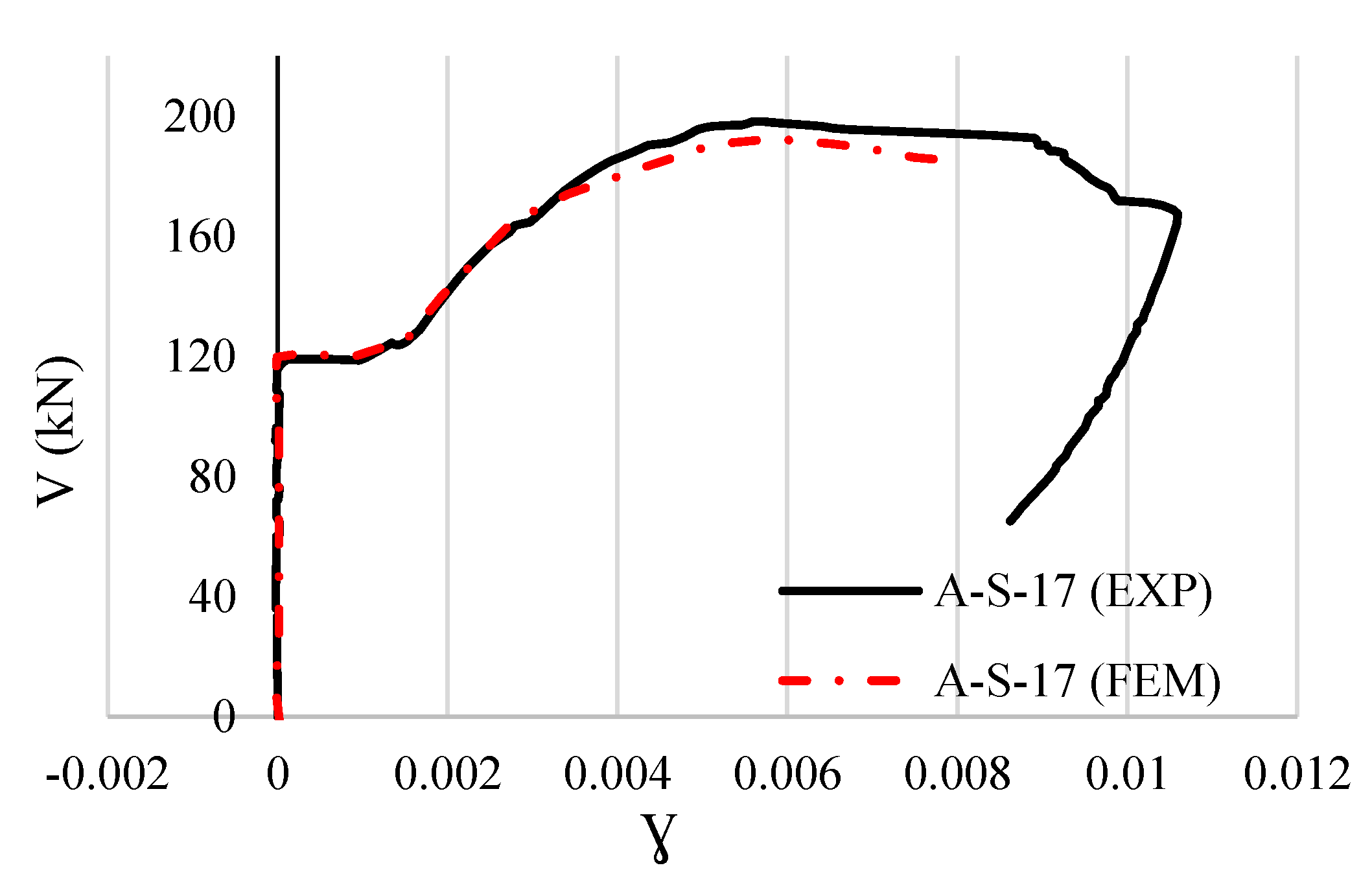
2.4. Validation of the FE Models

In order to evaluate the accuracy numerical model, the force-deformation curves and tensile crack pattern of the FE analysis were compared and validated with the experimental results [37]. Figure 6 compares the load-axial deformation curves of one of the reference beams (A-S-17) obtained from the FE analysis with the experimental results. In the experiment, the axial deformations were directly collected from the strain gauges (See Figure 2). As Figure 6 demonstrates, numerical curves of the load and axial deformations closely followed the experimental curves. The obtained yield loads from the numerical analysis in three directions of deformations, i.e., 45° deformation (ε45), horizontal deformation (εh), and vertical deformation (εv) were very close to that of the experimental tests. The yield forces at the inclined deformation angle of 45 of this beam from the experiment and FE analysis were 195 kN and 182 kN, respectively. The ultimate load of the numerical model at the 45-degree inclined deformation was 314 kN, which was close to 308 kN obtained from the experimental results. The obtained yield loads at the horizontal direction from the FE analysis and experiment were 226 kN and 227 kN, respectively. Meanwhile, the ultimate loads at the horizontal direction obtained from the FE analysis and experiment were 326 kN and 317 kN, respectively, which shows about 2.8% differences. Further, the yield forces in the vertical direction from the numerical and experimental analyses were 185 kN and 180 kN, respectively (about a 3% difference). The obtained ultimate load at the vertical direction from the numerical and experimental analyses were 325 kN and 316 kN, respectively, which indicates a 2.9% difference.
Figure 7 compares the curves for the shear force against the shear deformation of the A-S-17 beam obtained from the FE and the experimental analyses. The shear deformation was calculated using the following equation [37]
γ = 2ε45εhεv
It can be seen from Figure 7 that the curve trend of the shear force deformations calculated based on numerical and experimental analyses was almost the same. The yield shear force obtained from the experiment and FE analysis was 165 kN. Further, the maximum ultimate shear strengths calculated by the FE analysis and experimental results were 198 kN and 193 kN, respectively, which only indicate a 3% difference.
The results of the shear strength of the reference beams and beams strengthened with CFRP sheets obtained from the FE analysis were also compared with the experimental results, as shown in Table 7. As this table shows, the difference between the shear capacity of the beams obtained from the FE analysis and the experimental study was relatively small.
Figure 8 compares the crack patterns of the FE analysis and the experimental results for the A-C-17 and A-S-17 beams (reference beams). In the experimental study, the A-C-17 beam with continuous beam configuration had a major diagonal crack and several other diagonal (with 45° angle) cracks originated from the loading positions to the nearest support [37]. This failure mechanism is a typical shear-tensile failure in RC beams. Similarly, in the FE analysis diagonal cracks were also observed between the support and loading locations, as shown in Figure 8a. For the A-S-17 beam having the simply supported configuration, the diagonal cracks were almost the same and were mainly started from loading to the nearest support in the experimental test. The crack pattern of this beam in the FE analysis was also the same as the experiment, where several closed space diagonal cracks were started from the support and extended to the loading location, as shown in Figure 8b. Therefore, it can be concluded from the load-deformation curves, shear strength, and failure mechanism of the beams that there is a good agreement between the FE analysis and the experimental tests.

3. Results and Discussion

This section explains the results for the reference beams and five types of shear-strengthened beams (see Table 3) to evaluate the effectiveness of the shear strengthening by the CFRP grids and ECC. The results include the failure mechanism, load-axial deformations curves, and shear force-shear deformation curves. In addition, the shear capacity calculation formulas for RC beams strengthened with CFRP grids and ECC are given.

3.1. Failure Mechanism

In order to comprehensively study the failure mechanism of the beams, the crack patterns (tensile crack) and stress results of the numerical analysis are briefly discussed in this section. Since the shear behavior of simply supported beams was more profound, only the results of the simply supported beams are presented here. Figure 9 shows the crack patterns of a reference beam and beams strengthened with different methods at the ultimate load. The CFRP sheets slightly reduced the shear diagonal cracks and some of the flexural cracks, as shown in Figure 9b. In general, CFRP grids and ECC not only reduced the shear cracks but also reduced the flexural cracks of the beams, as shown in Figure 9c–f. By comparing the CRG5-S-17 beam with the CRG′5-S-17 beam (Figure 9c,e) and the CRG8-S-17 beam with the CRG′8-S-17 beam (Figure 9d,f), it can be seen that the beams with the larger CFRP grid size had a lesser number of shear cracks and smaller crack widths. Further, the beams strengthened with the larger cross-sectional area of CFRP grids (CRG8-S-17 and CRG′8-S-17) had smaller shear cracks as compared with those beams strengthened with the smaller cross-sectional area of CFRP grids (CRG5-S-17 and CRG′5-S-17). It is worth mentioning that the flexural cracks significantly reduced for the beam with the largest cross-sectional area of CFRP grids and smallest grid size (CRG8-S-17) as compared to other strengthened beams.
Figure 10 shows the stress distributions of the reference and strengthened simply supported beams in detail. For the reference beam, the stresses in the concrete diagonally span from the loading position to the supports (in both shear and moment areas), as shown in Figure 10a. Similarly, the stress concentration for reinforcements of the reference beam was at the stirrups and tensile bars below the loading position, as shown in Figure 10e. However, for the beam strengthened with CFRP sheets (CR-S-17), the stress distributions in the concrete (Figure 10b) and reinforcements (Figure 10f) were significantly reduced in shear and moment areas. The stress distributions in concrete and steel bars of the beams with CFRP grids and ECC (CRG5-S-17 and CRG8-S-17) were further reduced as compared to the reference beam (A-S-17) and beam with the CFRP sheet (CR-S-17). This indicated that the combined action of the CFRP grids with the ECC layers enhanced the shear capacity of the reinforced beams, and effectively limited the spread of concrete cracks. For the CFRP sheet of the CR-S-17 beam, the stress was diagonally distributed from the loading to the support, and the maximum stress was located in the vicinity of the support, as shown in Figure 10i. Further, the stress distributions of the CFRP grids of CRG5-S-17 and CRG8-S-17 beams were relatively similar; however, the maximum stress of CFRP grids of the CRG8-S-17 beam was about 12% larger than the CRG5-S-17 beam, as shown in Figure 10j,k. This is because the cross-sectional area of the CFRP grids of the CRG8-S-17 beam was larger than the CRG5-S-17 beam, which led to higher loading bearing capacity and stresses.

3.2. Load-Deformation Response

Figure 11 shows the load-deformation curves of reference and strengthened beams. It can clearly be seen that all of the strengthened beams had higher strength than the reference beam. The CRG8-S-17 and CRG5-S-17 beams had better load-deformation responses as compared with other beams. This means that the CFRP grid size is a governing factor in this shear-strengthening method. The load-deformation response of the beam improved as the CFRP grid size was reduced. Nevertheless, the load-deformation response of the CRG8-S-17 beam outperformed the CRG5-S-17 beams due to the larger stiffness of the CFRP girds. The maximum ultimate load of the CRG5-S-17 beam was 46.2%, 37.68%, and 37.68% larger than the reference beam at 45°, horizontal, and vertical deformations, respectively. Comparatively, the ultimate load of the CRG8-S-17 beam at 45°, horizontal, and vertical deformations was 2.5%, 2.4%, and 2.4% larger than the CRG5-S-17 beam, respectively, while the cross-sectional area of the CFRP gird of CRG8-S-14 was double that of CRG5-S-17. Although the load-deformation responses of the beam strengthened by CFRP sheets (CR-S-17) were better than the reference beam, its responses were less significant as compared with beams strengthened with CFRP grids and ECC. By comparing Figure 11a with Figure 11b,c, it can be seen that the effect of the gird size of CFRP girds was more profound for the load-deformation response at a 45-degree inclination than the horizontal and vertical deformation. The ultimate load of the CRG5-S-17 beam at a 45-degree inclination, horizontal, and vertical deformation was 7%, 4%, and 3%, respectively.
Table 8 summarized the results of the flexural cracking load (Pcr), the shear cracking load (Vcr), the ultimate load at an incline of 45 degrees, vertical, and horizontal deformations, and their corresponding strain values. For the continuous beam configuration (A-C-17), the flexural and shear cracking loads were slightly smaller than the simply supported beam (A-S-17). In addition, the ultimate shear loads of the continuous beam were smaller but with larger strains (in three directions) than the simply supported beam. In other words, the failure mode of the continuous beam failed flexural-shear failure. After strengthening the continuous beam with different configurations, the flexural and shear cracking loads were found to be larger than that of the simply supported strengthened beams. On the other hand, after strengthening beams with different schemes, the ultimate shear forces (in three directions) of the simply supported beam were larger than that of the continuous beam. This means that the shear strengthening of the continuous beam improves its serviceability state better than the ultimate state. Among all the strengthen schemes, the flexural and shear cracking loads as well as the ultimate loads were the largest for the strengthened beams with the largest cross-sectional area of CFRP grids and the smallest CFRP grid size (CRG8-C-17 and CRG8-S-17 beams). When the CFRP grid size increased (from 50 mm to 100 mm), the flexural and shear cracking loads as well as the ultimate loads of the beam decreased. However, when the cross-sectional area of the CFRP grid increased, the loading response of the beam also increased.
Figure 12 presents the shear force relationship with the shear deformation derived from Equation (1). Practically, there is shear deformation until the yield load is negligible and after this point, cracks develop on the concrete. Once the beams enter the strain hardening stage, the shear reinforcement yields, and eventually plastic deformation occurs until failure. It can be seen from Figure 12 that the shear strength of all strengthened beams was much larger than the reference beam at yield as well as the plastic stage. Similar to the load-axial deformation curves, the shear force-shear deformation curve of the CRG8-S-17 beam outperformed other strengthened beams. In addition, the beams strengthened with smaller CFRP grid sizes (CRG8-S-17 and CRG5-S-17) had higher shear capacity than the beams with bigger CFRP grid sizes (CRG′8-S-17 and CRG′5-S-17).
Table 9 summarizes the shear capacity and load contribution of each strengthening method for all the beams. In general, the improvement of the shear capacity of the simply supported beams strengthened with different schemes was more profound than the continuous beams. This was mainly because the simply supported beams were subjected to a pure shear load while the continuous beams were subjected to a shear-flexural load. The maximum increase in the shear force of the beam strengthened with CFRP sheets (CR-S-17) was about 31%. However, the maximum improvement of the shear for the beams strengthened with CFRP grids and ECC (CRG8-S-17) was 49%. As this table indicates, the effect of CFRP grid size was more profound in improving the shear capacity of the beam than the cross-sectional area of CFRP grids.

3.3. Analytical Model

Generally, the total shear capacity of concrete structures externally strengthened is simply the summation of the shear contribution of the concrete (VCON), the available shear of the steel shear reinforcement (VST), the shear contribution of externally bonded CFRP grid (Vg), and shear carried by the ECC (VECC):
V = Vcon + Vst + VECC + Vg
The shear carrying capacity of concrete (Vcon) is [44,45]:
V con ( V ECC )   =   β d β p β n f v c d b w d γ b
where, γ b is the safety factor ( γ b = 1.3), and d is the effective height of the beam. The value for coefficient βn relies on the bending moment and the stress caused by the axial forces and since no axial compressive force is applied in this research, βn = 1, and fvcd, βd, and βp can be obtained from the following equations:
f v c d = 0.20 f c 3
β d = 1000 d 4
β p = 100 P w 3
P w = A f b w d
where, f c is the compressive strength of the concrete, Pw is the longitudinal reinforcement ratio, bw is the width of the section, and Af is the cross-sectional area of the tension reinforcement.
The shear capacity of ECC-reinforced structural members can be calculated as [46,47]:
Vecc = Vc,ecc + Vf,ecc
where, Vc,ecc is the shear carried by the member, and Vf,ecc is the shear carried by fibers. The shear capacity equation of the ECC-reinforced members is similar to the shear capacity equation of concrete; however, with a smaller coefficient, which is 0.7. This is mainly due to the absence of coarse aggregates in ECC that weaken the interlocking of the aggregates. Accordingly, Vc,ecc and Vf,ecc are calculated as:
V c , e c c = 0.7 × 0.2 f e c c 3 × 1 d 4 × 100 ρ w 3 × t × d
V f , e c c = f t , e c c t a n β u × t × z
where, fecc and ft,ecc are the compressive and tensile yield strength of ECC, respectively, t is the ECC thickness, βu is the angle between the diagonal crack on the surface with the member axis and it is generally taken as 45 degrees. z is the distance between the location of the resultant compressive stress and the centroid of the tensile steel, which is generally equal to d/1.15.
The shear capacity of the stirrups is
V s t = A w f y sin α + cos α z S × γ b
where, fy is the yield strength of the shear rebar, Aw is the total cross-sectional area of the stirrups, α is the angle between the shear rebar with member axis, S is the stirrup spacing, and generally the γ b coefficient is 1.15.
Moreover, an analytical model for the shear capacity of FRP grids can be calculated by an analytical model given in the references [29,30]. The analytical model accounts for the shear contribution of the horizontal and vertical CFRP grids as well as the shear span ratio of the RC beams. The equation of for shear capacity of CFRP is:
V g = 2 · E W · [ ρ v · ε u v · ( sin α v + cos α v ) + K · ε u h sin α h + cos α h ] · Z γ b
where, αv and αh are angles between vertical and horizontal grids with axial orientation, respectively, ρv and ρh are the cross-sectional areas in vertical and horizontal grids per unit of length, respectively, k is the ratio between the shear contribution of vertical grids and horizontal grids, EW is the Young’s modulus of CFRP grids, d is the effective height of the beam, the value of the coefficient γ b is 1.15. εuv, and εuh are the effective strains of vertical and horizontal grids, respectively, which are:
ε u v = ( 1 0.0352 ρ v + 0.0079 ) 2 × 10 6
ε u h = k · ε u v
where, k is the comparing coefficient related to the contribution of the shear between vertical and horizontal grids and it is:
k = e 0.612   a d + 0.365 0.23
where, a is the shear span of the beam.
A comparison of the shear force of the strengthened beams obtained by the numerical analysis and the theoretical models [29,46] is made in Table 10. The shear capacity of the strengthened beams from the numerical analysis was relatively close to those obtained from the theoretical models. The average ratio of shear capacity of the beams obtained by the numerical analysis and the above analytical model was 1.04, which was close to unity. Further, the average ratio of shear capacity of the beams obtained by the numerical analysis and above analytical model by the Japan Society of Civil Engineers (JSCE) [46] was 1.07, which was also close to unity. Given that the analytical models slightly overestimate the shear capacity of the strengthened beams, it is safe to use them for design calculations.

4. Conclusions

This paper studies the shear capacity of RC beams strengthened with CFRP grids within externally bonded ECC layers through numerical analysis. For this purpose, two RC beams were selected from the literature [37] and modeled in Abaqus FE software [38]. Thereafter, the application of the proposed strengthening method for shear strengthening of the beams was investigated in terms of failure mechanism and load-deformation responses. Lastly, the analytical model for calculating the shear capacity of beams strengthened by this method was given. Based on the obtained results, the following conclusions are drawn:
  • The CFRP grids and ECC were effective in delaying and reducing the diagonal shear crack as well as the flexural cracks in the RC beam. Comparatively, the CFRP grids and ECC controlled the diagonal shear cracks in the beams better than the CFRP sheets. Stress analysis showed that the CFRP grid was the primary strengthening member for improving shear performance, while ECC layers mainly acted as bonding agents.
  • The effect of the shear strengthening of the simply supported beam with the proposed method was more profound as compared with the continuous beam. It was primarily due to the failure mechanism of the beams that the simply supported beam was designed to fail due to shear while the mode of the continuous beam was a shear-flexural failure. Nevertheless, the proposed shear strengthening also reduced the flexural cracks in the continuous beam.
  • The load-deformation responses of beams strengthened with CFRP grids and ECC showed significant improvement compared to reference beams and those strengthened with CFRP sheets. The shear capacity of the RC beams was greatly improved from 30% to 50% after strengthening with the CFRP grids and ECC.
  • The main governing factor for increasing the shear capacity of the beam with the proposed method was the CFRP grid size. The shear capacity of simply supported beams strengthened with smaller CFRP grid sizes was 8% and 10% larger than the simply supported beams strengthened with larger CFRP grid sizes, respectively. Therefore, as the CFRP grid size increased, the ultimate shear strength of the beam reduced.
  • The shear capacity of the beam strengthened by the CFRP grids and ECC was calculated using the analytical model and the Japan Society of Civil Engineers (JSCE). The average shear capacity ratios of the numerical results with those calculated based on the analytical model and JSCE were 1.04 and 1.07, respectively. While the analytical models slightly overestimated the shear capacity (compared to numerical results), they were deemed safe for design purposes.
  • In summary, this numerical study demonstrated the effectiveness of the proposed strengthening method in improving the shear behavior of RC beams. Future research should explore the application of this method in experimental studies.

Author Contributions

Software, M.S.G.; investigation, A.J., M.I., N.U. and E.K.; writing—original draft, M.S.G.; writing—review and editing, A.J.; project administration, A.J. All authors have read and agreed to the published version of the manuscript.

Funding

The support of the startup fund of Fuzhou University (XRC-22046) is also greatly acknowledged.

Data Availability Statement

Not applicable.

Conflicts of Interest

The authors declare no conflict of interest.

References

  1. Costa, A.; Appleton, J. Case studies of concrete deterioration in a marine environment in Portugal. Cem. Concr. Compos. 2002, 24, 169–179. [Google Scholar] [CrossRef]
  2. Safehian, M.; Ramezanianpour, A.A. Assessment of service life models for determination of chloride penetration into silica fume concrete in the severe marine environmental condition. Constr. Build. Mater. 2013, 48, 287–294. [Google Scholar] [CrossRef]
  3. Hanif, M.U.; Ibrahim, Z.; Ghaedi, K.; Javanmardi, A.; Rehman, S. Finite Element Simulation of Damage in RC Beams. J. Civ. Eng. 2018, 9, 50–57. [Google Scholar] [CrossRef]
  4. Mulk, S.; Usman, M.; Khan, A.; Usman, M.; Javanmardi, A.; Ahmad, A. Damage assessment of reinforced concrete beams using cost-effective MEMS accelerometers. Structures 2022, 41, 602–618. [Google Scholar] [CrossRef]
  5. Hanif, M.U.; Ibrahim, Z.; Ghaedi, K.; Hashim, H.; Javanmardi, A. Damage Assessment of Reinforced Concrete Structures using a Model-based Nonlinear Approach—A Comprehensive Review. Constr. Build. Mater. 2018, 192, 847–865. [Google Scholar] [CrossRef]
  6. He, W.; Wang, X.; Monier, A.; Wu, Z. Shear Behavior of RC Beams Strengthened with Side-Bonded BFRP Grids. J. Compos. Constr. 2020, 24, 04020051. [Google Scholar] [CrossRef]
  7. Wakjira, T.G.; Ebead, U. Hybrid NSE/EB technique for shear strengthening of reinforced concrete beams using FRCM: Experimental study. Constr. Build. Mater. 2018, 164, 164–177. [Google Scholar] [CrossRef]
  8. Ghaedi, K.; Ibrahim, Z.; Javanmardi, A.; Rupakhety, R. Experimental study of a new bar damper device for vibration control of structures subjected to earthquake loads. J. Earthq. Eng. 2021, 25, 300–318. [Google Scholar] [CrossRef]
  9. Sajan, K.C.; Bhusal, A.; Gautam, D.; Rupakhety, R. Earthquake damage and rehabilitation intervention prediction using machine learning. Eng. Fail. Anal. 2023, 144, 106949. [Google Scholar] [CrossRef]
  10. Khatibi, H.; Wilkinson, S.; Dianat, H.; Baghersad, M.; Ghaedi, K.; Javanmardi, A. Indicators bank for smart and resilient cities: Design of excellence cities. Built Environ. Proj. Asset Manag. 2021, 12, 5–19. [Google Scholar] [CrossRef]
  11. Marcinczak, D.; Trapko, T.; Musiał, M. Shear strengthening of reinforced concrete beams with PBO-FRCM composites with anchorage. Compos. Part B Eng. 2019, 158, 149–161. [Google Scholar] [CrossRef]
  12. Grace, N.F.; Sayed, G.A.; Soliman, A.K.; Saleh, K.R. Strengthening reinforced concrete beams using fiber reinforced polymer (FRP) laminates. ACI Struct. J. 1999, 96, 865–874. [Google Scholar] [CrossRef]
  13. Colalillo, M.A.; Sheikh, S.A. Behavior of shear-critical reinforced concrete beams strengthened with fiber-reinforced polymer-Experimentation. ACI Struct. J. 2014, 111, 1373–1384. [Google Scholar] [CrossRef]
  14. Rodrigues, H.; Arêde, A.; Furtado, A.; Rocha, P. Seismic behavior of strengthened RC columns under biaxial loading: An experimental characterization. Constr. Build. Mater. 2015, 95, 393–405. [Google Scholar] [CrossRef]
  15. Rodrigues, H.; Arêde, A.; Furtado, A.; Rocha, P. Seismic Rehabilitation of RC Columns Under Biaxial Loading: An Experimental Characterization. Structures 2015, 3, 43–56. [Google Scholar] [CrossRef]
  16. Rodrigues, H.; Furtado, A.; Arêde, A. Experimental evaluation of energy dissipation and viscous damping of repaired and strengthened RC columns with CFRP jacketing under biaxial load. Eng. Struct. 2017, 145, 162–175. [Google Scholar] [CrossRef]
  17. Ghaedi, K.; Ibrahim, Z.; Javanmardi, A.; Jameel, M.; Hanif, U.; Rehman, S.; Gordan, M. Finite Element Analysis of a Strengthened Beam Deliberating Elastically Isotropic and Orthotropic Cfrp Material. J. Civ. Eng. Sci. Technol. 2018, 9, 117–126. [Google Scholar] [CrossRef] [Green Version]
  18. Chaallal, O.; Nollet, M.-J.; Perraton, D. Shear Strengthening of RC Beams by Externally Bonded Side CFRP Strips. J. Compos. Constr. 1998, 2, 111–113. [Google Scholar] [CrossRef]
  19. Hadi, M.N.S. Retrofitting of shear failed reinforced concrete beams. Compos. Struct. 2003, 62, 1–6. [Google Scholar] [CrossRef]
  20. Adhikary, B.B.; Mutsuyoshi, H. Behavior of Concrete Beams Strengthened in Shear with Carbon-Fiber Sheets. J. Compos. Constr. 2004, 8, 258–264. [Google Scholar] [CrossRef]
  21. Al-Tersawy, S.H. Effect of fiber parameters and concrete strength on shear behavior of strengthened RC beams. Constr. Build. Mater. 2013, 44, 15–24. [Google Scholar] [CrossRef]
  22. Karzad, A.S.; Leblouba, M.; Al Toubat, S.; Maalej, M. Repair and strengthening of shear-deficient reinforced concrete beams using Carbon Fiber Reinforced Polymer. Compos. Struct. 2019, 223, 110963. [Google Scholar] [CrossRef]
  23. Yang, X.; Gao, W.Y.; Dai, J.G.; Lu, Z.D.; Yu, K.Q. Flexural strengthening of RC beams with CFRP grid-reinforced ECC matrix. Compos. Struct. 2018, 189, 9–26. [Google Scholar] [CrossRef]
  24. Ye, Y.Y.; Smith, S.T.; Zeng, J.J.; Zhuge, Y.; Quach, W.M. Novel ultra-high-performance concrete composite plates reinforced with FRP grid: Development and mechanical behaviour. Compos. Struct. 2021, 269, 114033. [Google Scholar] [CrossRef]
  25. Zeng, J.-J.; Zeng, W.-B.; Ye, Y.-Y.; Liao, J.; Zhuge, Y.; Fan, T.-H. Flexural behavior of FRP grid reinforced ultra-high-performance concrete composite plates with different types of fibers. Eng. Struct. 2022, 272, 115020. [Google Scholar] [CrossRef]
  26. Zeng, J.-J.; Pan, B.-Z.; Fan, T.-H.; Zhuge, Y.; Liu, F.; Li, L.-J. Shear behavior of FRP-UHPC tubular beams. Compos. Struct. 2023, 307, 116576. [Google Scholar] [CrossRef]
  27. Azam, R.; Soudki, K.; West, J.S.; Noël, M. Strengthening of shear-critical RC beams: Alternatives to externally bonded CFRP sheets. Constr. Build. Mater. 2017, 151, 494–503. [Google Scholar] [CrossRef]
  28. Blanksvärd, T.; Täljsten, B.; Carolin, A. Shear Strengthening of Concrete Structures with the Use of Mineral-Based Composites. J. Compos. Constr. 2009, 13, 25–34. [Google Scholar] [CrossRef]
  29. Guo, R.; Pan, Y.; Cai, L.; Hino, S. Study on design formula of shear capacity of RC beams reinforced by CFRP grid with PCM shotcrete method. Eng. Struct. 2018, 166, 427–440. [Google Scholar] [CrossRef]
  30. Guo, R.; Cai, L.; Hino, S.; Wang, B. Experimental study on shear strengthening of RC beams with an FRP grid-PCM reinforcement layer. Appl. Sci. 2019, 9, 2984. [Google Scholar] [CrossRef] [Green Version]
  31. Cai, L.; Liu, Q.; Guo, R. Study on the shear behavior of RC beams strengthened by CFRP grid with epoxy mortar. Compos. Struct. 2021, 275, 114419. [Google Scholar] [CrossRef]
  32. Chen, C.; Cai, H.; Cheng, L. Shear Strengthening of Corroded RC Beams Using UHPC–FRP Composites. J. Bridg. Eng. 2021, 26, 1–14. [Google Scholar] [CrossRef]
  33. Zhang, R.; Meng, Q.; Shui, Q.; He, W.; Chen, K.; Liang, M.; Sun, Z. Cyclic response of RC composite bridge columns with precast PP-ECC jackets in the region of plastic hinges. Compos. Struct. 2019, 221, 110844. [Google Scholar] [CrossRef]
  34. Liu, H.; Zhang, Q.; Gu, C.; Su, H.; Li, V. Self-healing of microcracks in Engineered Cementitious Composites under sulfate and chloride environment. Constr. Build. Mater. 2017, 153, 948–956. [Google Scholar] [CrossRef]
  35. Pan, J.; Lu, B.; Gu, D.; Xia, Z.; Xia, T. Mechanical behavior of rectangular steel-reinforced ECC/concrete composite column under eccentric compression. Trans. Tianjin Univ. 2015, 21, 269–277. [Google Scholar] [CrossRef]
  36. Ge, W.; Ashour, A.; Cao, D.; Lu, W.; Gao, P.; Yu, J.; Ji, X.; Cai, C. Experimental study on flexural behavior of ECC-concrete composite beams reinforced with FRP bars. Compos. Struct. 2019, 208, 454–465. [Google Scholar] [CrossRef] [Green Version]
  37. Pellegrino, C.; Modena, C. Fiber-reinforced polymer shear strengthening of reinforced concrete beams: Experimental study and analytical modeling. ACI Struct. J. 2006, 103, 720–728. [Google Scholar] [CrossRef]
  38. Simulia, D. ABAQUS 6.14 Analysis User’s Manual. Abaqus 6.14 Documentation; ABAQUS M, Hibbitt, Karlsson and Sorensen, Inc.: Providence, RI, USA, 2016. [Google Scholar]
  39. Fink, J.; Petraschek, T.; Ondris, L. Push-out test parametric simulation study of a new sheet-type shear connector. In Projeket an Zentralen Applikationsselenrvern, Berichte; Zentraler Informatikdienst der Technischen University Wien: Wien, Austria, 2006; pp. 131–153. [Google Scholar]
  40. Zheng, Y.Z.; Wang, W.W.; Brigham, J.C. Flexural behaviour of reinforced concrete beams strengthened with a composite reinforcement layer: BFRP grid and ECC. Constr. Build. Mater. 2016, 115, 424–437. [Google Scholar] [CrossRef] [Green Version]
  41. Singh, S.B.; Patil, R.; Munjal, P. Study of flexural response of engineered cementitious composite faced masonry structures. Eng. Struct. 2017, 150, 786–802. [Google Scholar] [CrossRef]
  42. Nippon Steel Chemical & Material. Available online: https://www.nscm.nipponsteel.com (accessed on 10 April 2023).
  43. Kameda, Y.; Nemoto, M.; Mitani, K.; Kawase, Y.; Ashino, T. Pier Strengthening Technique Using Carbon Fiber Grid and under Water Curing Type Resin. Nippon. Steel Sumitomo Met. Tech. Rep. 2017, 115, 99–108. [Google Scholar]
  44. GB 50208-2011; Code for Acceptance of Construction Quality of Underground Waterproof. Standardization Administration of the People’s Republic of China: Beijing, China, 2011.
  45. GB/T 1499.2-2007; Steel for the Rein-Forcement of Concrete-Part 2: Hot Rolled Ribbed Bars. Standards Press of China: Beijing, China, 2007.
  46. Yokota, H.; Rokugo, K.; Sakata, N. Japan Society of Civil Engineers (JSCE): Recommendations for Design and Construction of High-Performance Fiber Reinforced Cement Composites with Multiple Fine Cracks (HPFRCC); Springer: Tokyo, Japan, 2008. [Google Scholar]
  47. Li, H.; Leung, C.K.Y.; Xu, S.; Cao, Q. Potential use of strain hardening ECC in permanent formwork with small scale flexural beams. J. Wuhan Univ. Technol. Mater. Sci. Ed. 2009, 24, 482–487. [Google Scholar] [CrossRef]
Figure 1. Details of the strengthening beams by CFRP grids with the ECC method.
Buildings 13 01034 g001
Figure 2. Schematic diagram of the loading position, support conditions, and the reinforcement detailing of the beams [37].
Buildings 13 01034 g002
Figure 3. Loading and boundary conditions of (a) continuous beam, and (b) simply supported beam models in the FE software.
Buildings 13 01034 g003
Figure 4. Constitutive material models used in FE modeling [40,41].
Buildings 13 01034 g004
Figure 5. Mesh detailing of the reference beam model in FE software.
Buildings 13 01034 g005
Figure 6. Comparison of the load-axial deformation curves of the reference beam (A-S-17) obtained from numerical analysis and the experiment [37].
Buildings 13 01034 g006
Figure 7. Comparison of the shear force-shear deformation curves of the reference beam (A-S-17) obtained from numerical analysis and the experiment [37].
Buildings 13 01034 g007
Figure 8. Concrete crack patterns of (a) A-C-17, and (b) A-S-17 beams.
Buildings 13 01034 g008
Figure 9. Concrete crack patterns of (a) A-S-17, (b) CR-S-17, (c) CRG5-S-17, (d) CRG8-S-17, (e) CRG′5-S-17, and (f) CRG′8-S-17 beams.
Buildings 13 01034 g009
Figure 10. Stress distribution of reference and strengthened beams.
Buildings 13 01034 g010aBuildings 13 01034 g010b
Figure 11. Load-axial deformation curves of the reference and strengthened beams.
Buildings 13 01034 g011
Figure 12. Shear force-shear deformation curves of reference and strengthened beams [37].
Buildings 13 01034 g012
Table 1. General parameters and their effects using FRP materials for the shear strengthening RC beams.
Ref.Type of Shear Strengthening of BeamsParametersEffect
[6]BFRP grid with epoxy resinEpoxy resin
  • Improve the bonding interface between the BFRP gird and the concrete interface
  • Control the diagonal cracks
[6]BFRP sheets or BFRP gird with epoxy resinBFRP sheets
BFRP gird
  • BFRP sheets fail due to premature failure debonding, while BFRP grids prevent the premature failure
[6]BFRP gridGrid orientation (0° and 45°)
  • Increasing the grid angle to 45° significantly improves the shear performance in terms of crack resistance and maximum shear capacity
[29]CFRP grid with PCM shotcreteCFRP Grid size
  • Smaller grid interval leads to higher shear strength
[27]CFRP sheet with epoxy and CFRP gird with mortarCFRP sheet
CFRP grid
Mortar and epoxy
  • Mortar able to better control the diagonal cracks
  • CFRP gird with mortar offers better ultimate shear strength
[28]CFRP grid with MBCGrid size
  • Smaller grid size leads to higher ultimate shear strength
Table 2. Details of beams in the experimental work (adapted with permission from [37]; copyright 2006 American Concrete Institute). (Unit: mm.)
No.BeamTension
Reinforcement
ρStirrup
Diameter
Stirrup
Spacing
ρwStrengthening
Layer
a/dBeam Configuration
1A-C-174φ30 mm0.07581700.00392-3Continuous
2A-S-174φ30 mm0.07581700.00392-3Simply supported
3CR-C-174φ30 mm0.07581700.00392CFRP3Continuous
4CR-S-174φ30 mm0.07581700.00392CFRP3Simply supported
Table 3. Details of the beams (adapted with permission from [37]; copyright 2006 American Concrete Institute). (Unit: mm.)
SeriesNo.BeamTension
Reinforcement
ρStirrup
Dia.
Stirrup
Spacing
ρwStrengthening LayerCFRP Grid TypeGrid Size, S
(mm × mm)
a/dBeam
Configuration
Reference
beams
1A-C-174φ30 mm0.07581700.00392---3Continuous
2A-S-174φ30 mm0.07581700.00392---3Simply supported
Series I3CR-C-174φ30 mm0.07581700.00392CFRP--3Continuous
4CR-S-174φ30 mm0.07581700.00392CFRP--3Simply supported
Series II5CRG5-C-174φ30 mm0.07581700.00392CFRPG5 + ECCCR550 × 503Continuous
6CRG5-S-174φ30 mm0.07581700.00392CFRPG5 + ECCCR550 × 503Simply supported
Series III7CRG8-C-174φ30 mm0.07581700.00392CFRPG8 + ECCCR850 × 503Continuous
8CRG8-S-174φ30 mm0.07581700.00392CFRPG8 + ECCCR850 × 503Simply supported
Series IV9CRG′5-C-174φ30 mm0.07581700.00392CFRPG5 + ECCCR5100 × 1003Continuous
10CRG′5-S-174φ30 mm0.07581700.00392CFRPG5 + ECCCR5100 × 1003Simply supported
Series V11CRG′8-C-174φ30 mm0.07581700.00392CFRPG8 + ECCCR8100 × 1003Continuous
12CRG′8-S-174φ30 mm0.07581700.00392CFRPG8 + ECCCR8100 × 1003Simply supported
Note: CFRPG is the CFRP grids.
Table 4. Mechanical properties of steel reinforcement.
Bar Dia.
(mm)
Area
(mm2)
Yield Stress
(MPa)
Ultimate Strain
(%)
Ultimate Stress (MPa)Modulus of Elasticity (GPa)
30706.55340.15717193
850.245340.15717193
Table 5. Mechanical properties of CFRP girds used in the simulation [23,43].
GradeCross-Sectional Area of Bar (mm2)Interval of Grids, S
(mm × mm)
E11 (GPa)G12
(GPa)
υ 12 XT
(MPa)
XC
(MPa)
YT
(MPa)
YC
(MPa)
SL
(MPa)
ST
(MPa)
CR513.250 × 5010040.29200060012001505050
100 × 100
CR826.450 × 5010040.29200060012001505050
100 × 100
Notes: E11: longitudinal elasticity modulus, G12: shear modulus, υ 12 : Poisson’s ratio, XT: tensile strength in fiber direction, XC: compressive strength in fiber direction, YT: tensile strength in matrix direction, YC: compressive strength in matrix direction, SL: longitudinal shear strength, and ST: transverse shear strength.
Table 6. Mechanical properties of ECC (adapted with permission from [23]; copyright 2018 Elsevier).
MaterialTensile
Strength
(MPa)
Elastic
Modulus
(GPa)
Maximum
Strain (%)
Compressive
Strength (MPa)
ECC3.816.93.0430.2
Table 7. Comparison of the shear strength of the beams from the numerical and experimental [37].
BeamsVFEM (kN)VEXP (kN)Difference (%)
A-C-17183.57185.20.9
A-S-17192.74198.12.71
CR-C-17231.50238.13
CR-S-17253.02247.32.26
Table 8. Summary of loads and strain of the beams.
BeamPcr (kN)Vcr (kN)Pu45 (kN)εu45Puv (kN)εuvPuh (kN)εuh
A-C-17113.00157.00293.030.00987311.090.01128314.470.00236
A-S-17119.00165.00308.460.00940326.360.01074326.330.00225
CR-C-17130.78218.30327.060.00921342.040.01101336.340.00221
CR-S-17128.67210.47403.000.00923418.860.01010426.690.00225
CRG5-C-17197.50300.40380.790.00789404.050.00900367.480.00190
CRG5-S-17168.00257.00450.960.00725449.330.00829449.290.00175
CRG8-C-17215.00318.50383.460.00781405.850.00889406.910.00186
CRG8-S-17183.00270.00462.190.00710460.530.00809460.480.00169
CRG′5-C-17180.00274.00346.890.00823369.510.00940361.270.00199
CRG′5-S-17130.00226.87420.870.00815431.830.00942435.550.00197
CRG′8-C-17199.00294.00356.040.00783378.170.00923400.760.00193
CRG′8-S-17144.50215.00428.070.00786437.030.00813440.510.00187
Table 9. Summary of shear capacity of beams.
BeamVTotal
(kN)
Shear Span Ratio, (a/d)Increase in Shear Strength (%)VFRP grid + ECC
(kN)
VFRP (kN)
A-C-17183.573---
A-S-17192.743---
CR-C-17231.50326.12-47.93
CR-S-17253.02331.28-60.28
CRG5-C-17240.54331.0456.97-
CRG5-S-17280.93345.7588.19-
CRG8-C-17245.71333.8662.15-
CRG8-S-17287.93349.3895.19-
CRG′5-C-17238.54329.9554.98-
CRG′5-S-17265.35337.872.61-
CRG′8-C-17240.20330.8556.64-
CRG′8-S-17268.71339.4275.97-
Table 10. Comparison of the shear capacity of beams obtained by the theoretical model and numerical analysis.
BeamVFEM (kN)V [29] (kN)V [46] (kN)VFEM/V [29]VFEM/V [46]
CRG5-C-17240.54230.28221.931.051.08
CRG5-S-17280.93266.88259.861.051.08
CRG8-C-17245.71240.41229.401.021.05
CRG8-S-17287.93269.21269.211.071.10
CRG′5-C-17238.54229.54220.861.041.08
CRG′5-S-17265.35260.12252.491.041.05
CRG′8-C-17240.20233.99228.421.031.05
CRG′8-S-17268.71265.80257.531.011.04
Disclaimer/Publisher’s Note: The statements, opinions and data contained in all publications are solely those of the individual author(s) and contributor(s) and not of MDPI and/or the editor(s). MDPI and/or the editor(s) disclaim responsibility for any injury to people or property resulting from any ideas, methods, instructions or products referred to in the content.

