Article

Experimental and Numerical Analyses on the Fire Resistance of Timber–Concrete Composite Boards Using an Innovative Form of Partial Protection

1
College of Civil Engineering, Nanjing Tech University, Nanjing 211816, China
2
Zhejiang Mairui Robot Co., Ltd., Hangzhou 311200, China
*
Author to whom correspondence should be addressed.
Buildings 2023, 13(3), 725; https://doi.org/10.3390/buildings13030725
Submission received: 18 January 2023 / Revised: 9 February 2023 / Accepted: 22 February 2023 / Published: 9 March 2023
(This article belongs to the Special Issue Timber, Bamboo and Hybrid Structures)

Abstract

:
Compared with traditional timber boards, timber–concrete composite (TCC) boards demonstrate a higher rigidity and bearing capacity, improved vibration, and better behavior under seismic conditions. However, they become charred when exposed to fire due the combustibility of timber, and the fire safety of this material is considered essential. In this research, 60 min fire exposure tests and residual load-carrying capacity tests following fire exposure were carried out on three full-scale composite boards, two of which were covered with an innovative form of gypsum board protection. The effect of the innovative protection on the temperature field and fire resistance of the TCC boards was studied in detail. The test results indicate that the fire resistance of the TCC boards was effectively improved by using the innovative protection. If the coverage ratio is identical, a wider single gypsum board can demonstrate a slight increase in residual carrying capacity. Finite element models of TCC boards were established to investigate the temperature field during fire exposure and the residual load-carrying capacity of the TCC boards after fire exposure, demonstrating high applicability and accuracy. The conclusions in this paper can provide reference for fire design in engineering.

1. Introduction

Mass timber products, especially cross-laminated timber (CLT), present the advantages of being environmentally friendly, lowering costs, and shortening construction periods [1]. Thus, they have been widely used in building structures [2,3]. Timber–concrete composite (TCC) boards are usually made of reinforced concrete boards and timber deck, with the two materials connected by shear connectors. Compared with the traditional timber boards, TCC boards demonstrate a higher rigidity and bearing capacity, improved vibration, and better behavior under seismic conditions [4,5]. Thus far, numerous studies have been carried out to study the structural performance of TCC boards at room temperature [6,7,8,9]. Mai et al. [6] studied the shear connectors in TCC boards and found that 45° inclined screw connectors demonstrated good stiffness and bearing capacity. Mai et al. [7] conducted static and dynamic tests to research the bending behavior of CLT–concrete composite boards using bi-directional, cross-inclined screws as shear connectors. Bao et al. [8] studied the structural performance of CLT–concrete composite boards with inclined, self-tapping screw connectors through testing and found that CLT–concrete composite boards exhibited great flexural performance.
Due to the combustibility of timber, TCC boards become charred when exposed to fire, leading to a reduction in the load-carrying capacity of TCC boards. The fire safety of this material is considered essential if it is to be used in high-rise buildings [10,11,12]. Many experimental studies on the fire resistance of TCC systems have been carried out [13,14,15,16]. Frangi et al. [15] conducted tests to study the fire resistance of a TCC beam with screw connectors and found that increasing the wood thickness on the side of the screw connectors can effectively improve the fire resistance of the TCC beam. Shephard et al. [16] studied the fire behavior of a CLT–concrete composite board using inclined screws as shear connectors through fire exposure tests. The results indicated that although the charred timber had fallen off, the TCC board still demonstrated good fire resistance, and the shear connectors were always able to provide combined action. Due to the high cost of the test and the limitations of data acquisition, for example, the distribution of the whole temperature field of the components under fire, the variation of the internal stress and strain of the components, and the details of the loading process were not obtained. A finite element model can effectively simulate the temperature field and mechanical properties of TCC boards under fire [17,18]. Du et al. [17] established a finite element model to investigate the influencing factors on the fire resistance of TCC beams and found that the width of the timber beam determines the size of the remaining effective section, and that increasing the thickness of the concrete board can effectively improve the fire resistance. Bedon and Fragiacomo et al. [18] studied the TCC beams proposed by Frangi [15]. By using a different finite element software, the structural behavior under fire was simulated, and they found that the prediction was accurate. These studies demonstrated that although TCC boards have better fire resistance, there is still room for improvement. The fire resistance of CLT, generally used in TCC boards, is related to the performance of its adhesive [19]. When the adhesive layer reaches a certain temperature, the timber will fall off, increasing the charring rate. Recently, Hozjan et al. [20] made a comprehensive summary of TCC boards under fire conditions, pointing out that the test data are limited.
In order to achieve the desired safety level and meet code requirements [21], many researchers used gypsum board protection on the fire-exposed side of the boards to improve the fire resistance [22]. EN1995-1-2 21 pointed out that the use of gypsum board will delay the starting time of timber charring in a fire, and the formula for calculating the rate of timber char and the failure time of gypsum board in a fire were provided. Many researchers [23,24,25,26] studied the fire resistance of timber panels encased in different forms and thicknesses of gypsum board and found that the gypsum board is effective in delaying the time at which the fire-exposed timber begins to char. Batista et al. [23,24] studied the fire resistance of timber panels protected with gypsum board and found that a single layer of 16 mm Type X gypsum board, applied directly, provided a protection time of over 30 min. A calculation method for improving the fire resistance of timber covered with gypsum board was provided by White, and the times assigned to protective membranes were listed. Osborne et al. [25] experimentally studied the protective effect of Type X gypsum board on CLT and pointed out that two layers of 13 mm Type X gypsum board can increase the fire resistance limit by 50 min, while a single layer of 16 mm Type X gypsum board can increase the fire resistance limit by 30 min. Results were also presented in a study on the improvement of the fire resistance of Type X gypsum board for timber panels conducted by Hasburgh et al. [26].
In the studies above, researchers commonly used gypsum boards to completely protect the fire-exposed side of the timber. Although the fire resistance was improved, the unique and beautiful timber grain was completely hidden. The tests were almost all carried out on timber board, and there are fewer research studies performed on composite boards protected by gypsum boards. In order to improve this situation, this paper proposes an innovative form of partial protection which can expose the timber, reduce economic costs, and improve the fire resistance of a TCC board. First, the material tests, which were performed at ambient temperatures, were described. Then, three full-scale fire tests on CLT–concrete composite boards were carried out to evaluate the improvement in the fire resistance of the composite boards using this form of protection. Afterwards, the residual compressive bearing capacity of the composite boards after a fire was tested. Finally, a numerical simulation of the experiment was proposed to provide an accurate simulation method.

2. Materials and Methods

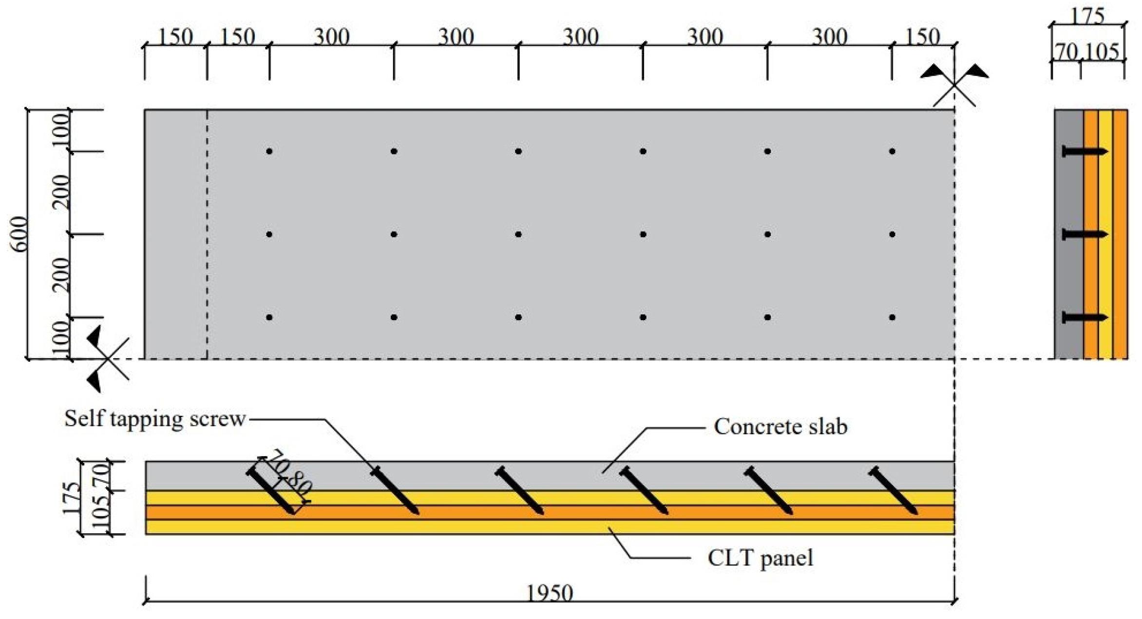
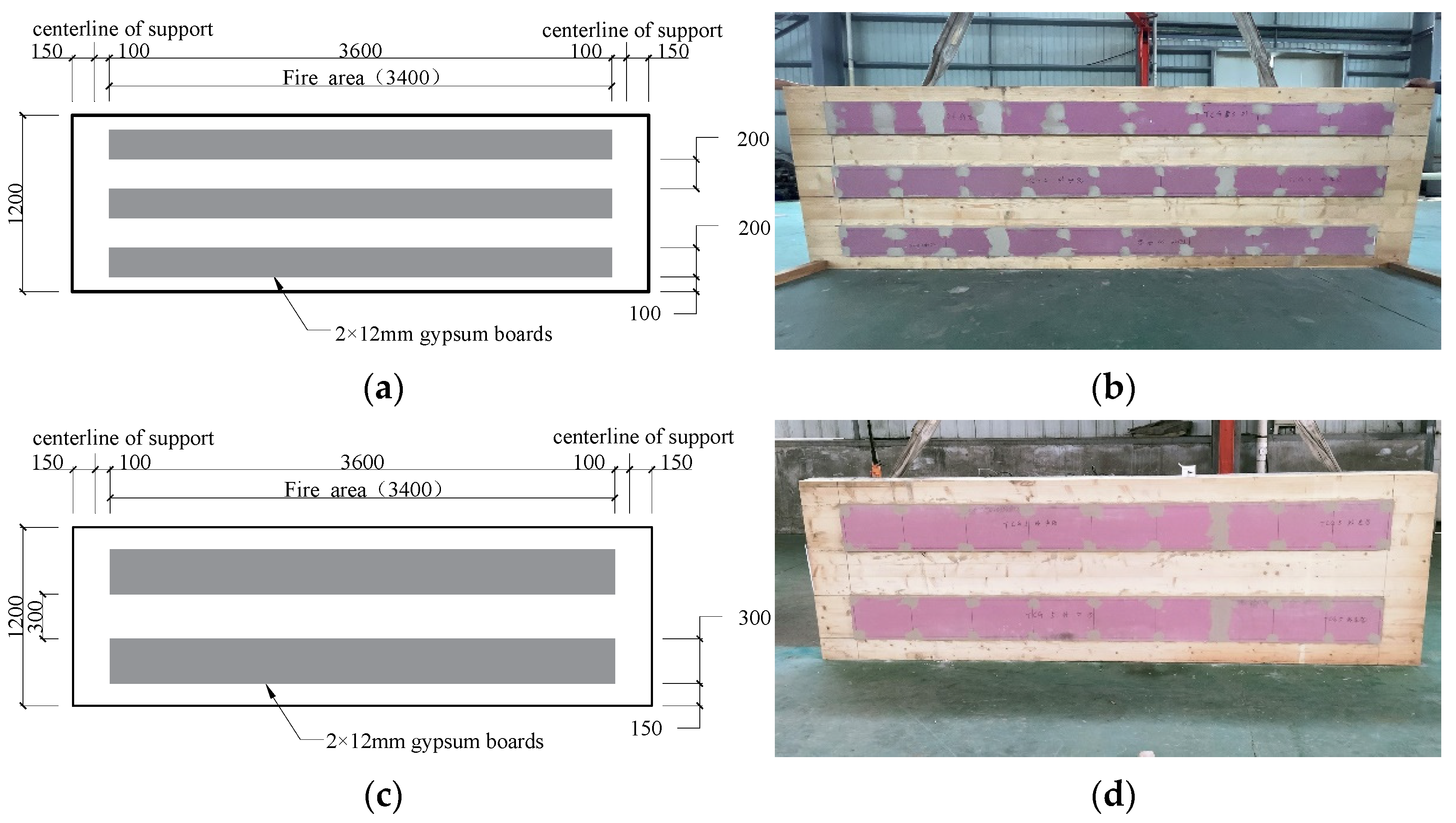
2.1. CLT–Concrete Composite Specimens

Three full-scale CLT–concrete composite board specimens with self-tapping screw connections were designed and assembled. The principal variable of the composite board specimens TCG2 and TCG3 was the form of protection covering the fire-exposed face. The control specimen TCC1 was constructed without protection. The parameters of the composite board specimens are listed in Table 1. The unloaded specimens were designed for 60 min of fire exposure.
Regarding the composite board specimens, a 3 ply, 105 mm thick CLT panel was connected to a 70 mm thick concrete board through self-tapping screw connections. The CLT–concrete composite specimens were 1200 mm wide and 3900 mm long, as shown in Figure 1. The diameter of the longitudinal and transverse reinforcing steel bars in the concrete was 8 mm. The spacing of the steel bar was 150 mm. The screws were drilled into the CLT panel with an inclination angle of 45°, angled away from the centerline and parallel to the length of the panel, to connect the CLT panel and the concrete board. Along the 1200 mm width, the spacing of the screws was 200 mm in the center and 100 mm from the edges. In the long direction, the screws were spaced at 300 mm both in the center and from either end. The embedded length of the self-tapping screws, which had a diameter of 12 mm, into the timber and concrete was 80 mm and 70 mm, respectively.
As shown in Figure 2, the composite board specimens TCG2 and TCG3 had the same coverage ratio of 50% of the Type X gypsum boards, but the width of the single protected area varied between them. The protection of the composite board specimen TCG2 consisted of three areas that were 200 mm wide. Along the 1200 mm width, the protected area was spaced 200 mm in the center and 100 mm from the edges. The single plasterboard width of the composite board specimen TCG3 was 300 mm. Along the 1200 mm width, the protected area was spaced 300 mm in the center and 150 mm from the edges. For either TCG2 or TCG3, along the 3900 mm long direction, the protected area was spaced 250 mm from the edges. Double 12.7 mm Type X gypsum boards were used for each protected area. The 50 mm long screws were used to attach the gypsum boards directly to the CLT. In the long direction, screws were spaced at 305 mm in the center. In the short direction, for the 200 mm width and the 300 mm width, the screws were spaced at 160 mm and 260 mm in the center, respectively. If there was a joint, the screws were located 20 mm from both sides of the joint. The joints of the gypsum boards were staggered between the base layer and face layer. The heads of the exposed screws and any exposed joints were covered with joint compound prior to the tests.

2.2. Materials

Spruce was used in the CLT panels. The thickness of each layer was 35 mm, and the strength of CLT was determined to be E3 according to ANSI/PRG320 [27]. Material tests were performed to obtain the mechanical properties. The average compressive strength, bending strength, and modulus of elasticity of the timber were 18.8 MPa, 29.3 MPa, and 10,102 MPa, respectively. The average moisture and density were 12.45% and 490 kg/m3, respectively. Through relevant cubic tests, the average compressive strength of the concrete was determined to be 29.5 MPa.
In addition, to measure the shear behavior of the connectors, push-out tests were performed by Bao et al. [8]. The dimensions and test setup of the push-out specimens are shown in Figure 3. According to the results, the slip modulus and the shear strength of a single screw were 29.1 kN/mm and 22.3 kN, respectively.

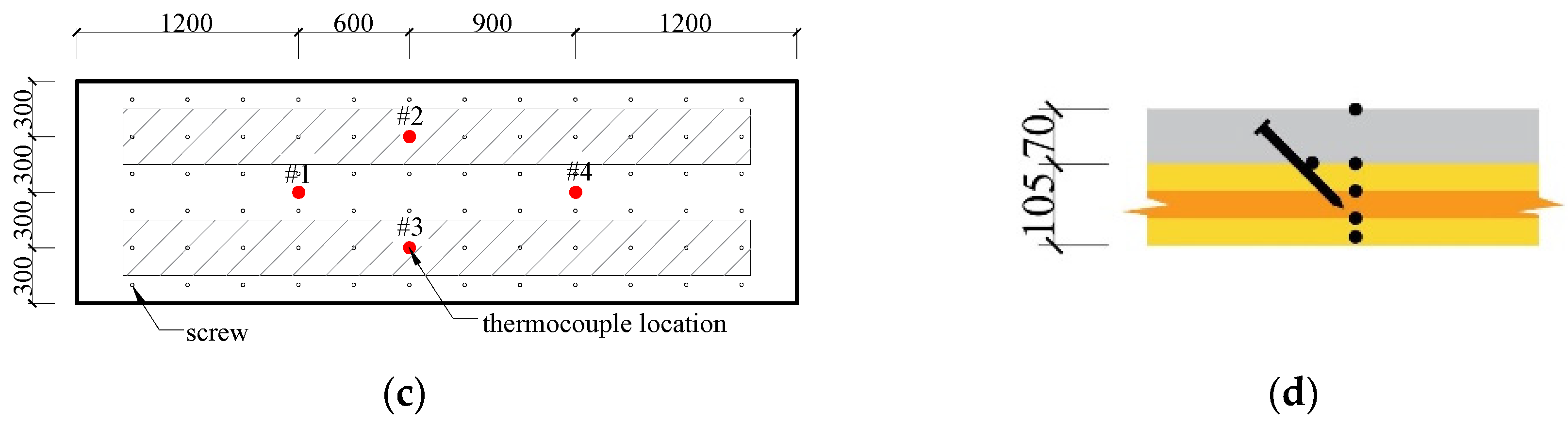
2.3. Large-Scale Fire Tests

Fire tests were performed in a large-scale horizontal fire furnace, following the ISO 834 standard heating curve [28], and lasting for 60 min. For convenient extinguishing, no load was applied during the fire tests, as shown in Figure 4. To simulate one-dimensional fire exposure, fire-resistant cotton was wrapped around the edges of the specimens.
The temperature distribution was measured using Type K thermocouples. Four locations were selected for each set of thermocouples, including the fire-exposed timber and the protected area. Five thermocouples were embedded at each location at depths of 10 mm, 35 mm, 70 mm, and 105 mm (the timber–concrete interface) and on the fire-unexposed face of the specimens. The locations of the thermocouples are shown in Figure 5. At locations #2 and #3 of specimens TCC1 and TCG3, a thermocouple was also placed in contact with the shear connector and epoxied in place.

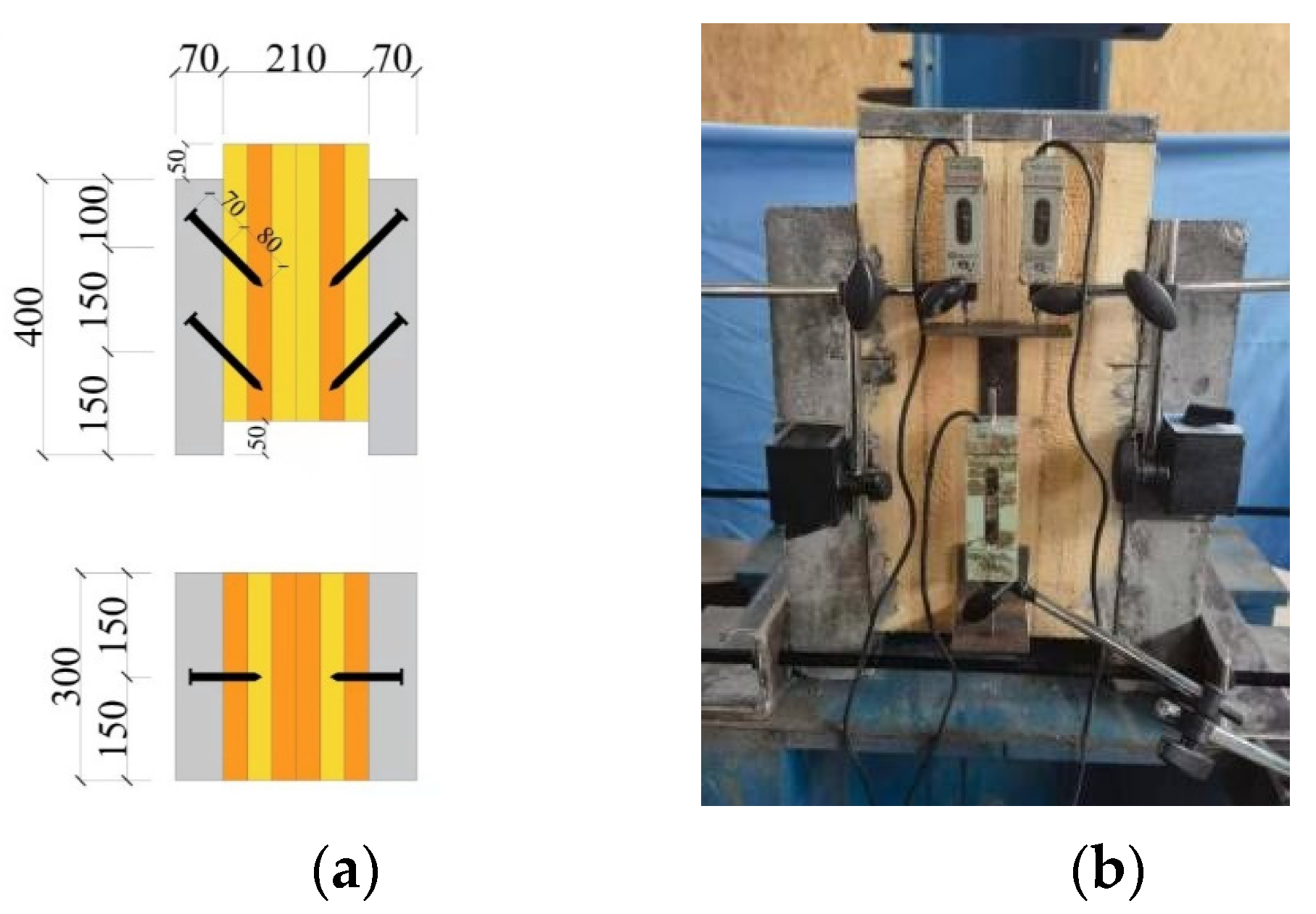
2.4. Residual Load-Carrying Capacity Tests after Fire

After the fire tests, the charred timber of the three specimens was removed, and residual load-carrying capacity tests were performed using the four-point bending method. The apparatus used for the residual load-carrying capacity tests is shown in Figure 6. A 32 T hydraulic jack was used to apply the loads. According to GB/T 50329-2012 [29], steel beams were used to distribute the load over the two loading points. The distance between the hinge supports was 150 mm. The loading process was divided into preloading and loading. The purpose of the preloading was to eliminate interface gaps before the tests and check whether the test instrument was working properly. The preloading ceased when the load reached 5 kN, lasted for 5 min, and was followed by unloading. For continuous loading, a loading method without impact effect was adopted. Mid-span loading was applied step by step. Each load increment was 10 kN and lasted for 1 min. When the specimen experienced obvious fracture or the load dropped to 80% of the ultimate load, the specimen was judged to be damaged. The displacement transducer was installed at the mid-span to capture the deflection of the mid-span.

3. Results and Discussion

3.1. Fire Tests

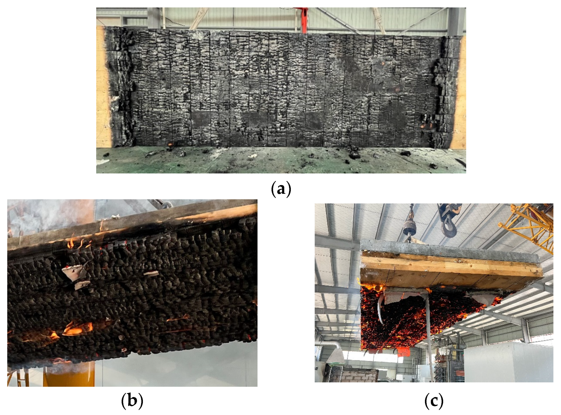
3.1.1. Experimental Phenomena

After 60 min of fire exposure, the burners were quickly turned off, and the specimens were lifted out for extinguishing. As shown in Figure 7, because of the effect of gravity on the charred timber, the timber on the fire-exposed face of specimen TCC1 partly fell off. However, it was observed that almost no charred timber fell from specimens TCG2 and TCG3 when they were lifted out from the furnace, even from the unprotected area. Due to the gaps between the embryo materials and the property of wood shrinking under heat, many cracks were observed in specimen TCC1. This would speed up the heat transfer at the cracks. However, because of the partial protection, this situation was greatly improved in specimens TCG2 and TCG3. Moreover, it was observed that the ends of all the screws of the three TCC boards were covered with timber and were not exposed.

3.1.2. Temperature Distribution

Figure 8 shows the comparison of the ISO 834 standard heating curve and the furnace temperature curve. The average temperature distribution of each measuring point during the fire tests is shown in Figure 9. During the 60 min fire test, only the measuring points 10 and 35 mm away from the fire-exposed face had a significant temperature rise. The time–temperature curves of these two measuring points under fire exposure are shown in Figure 10. There was a temperature plateau when the temperature reached 100 °C because the evaporation of water in the wood absorbed a large amount of heat; thus, the specific heat of the wood increased, and the change in the specific heat of wood with temperature was consistent with that in EN 1995-1-2 [22]. The experimental results show that the longer the distance from the fire-exposed side, the longer the duration of the temperature plateau of 100 °C.
By comparing the temperature curves of three CLT–concrete composite board specimens, it was found that the temperature rising speed of specimen TCC1 was significantly faster than that of specimens TCG2 and TCG3. The temperature rising speed of the exposed face of the wood area without protection for specimens TCG2 and TCG3 was also lower than that of specimen TCC1. On one hand, the timber on the fire-exposed face of specimen TCC1 charred and cracked with the increase in, and some charred timber fell off, leading to an increase in heat transfer and an increase in temperature. In addition, the gypsum boards in the protected area affected the temperature increase in the unprotected area. When the gypsum boards were exposed to a fire, the free water was driven off first, absorbing a small amount of heat, and then the water of crystallization was driven off, absorbing a large amount of heat [30]. In this process, the temperature around the gypsum boards was lowered, and there was a delay in the evolution of temperature until the gypsum boards had been completely dehydrated [30]. These results indicate that this form of partial protection delayed the development of the temperature field of the timber panel and had a good fire-protective effect on the timber panel.
All other measuring points of each specimen were below 40 °C during the test, close to the room temperature of 20 °C. The maximum average temperature at the screw connectors of specimen TCC1 was 31 °C at 60 min (the end of the test). When they were only 10 °C hotter than the timber at the same location, the mechanical properties of the shear connector were not changed. The concrete also retained its ambient temperature material properties in tension and compression [31] when the temperatures were not higher than 100 °C.

3.1.3. Charred Depth and Charring Rate

With the increase in fire exposure time, the timber on the fire-exposed face of the TCC specimens was charred. Due to the reduction in the cross-sections of the timber, the loading carrying capacity of the structural components decreased [32]. It was generally assumed that 300 °C is the critical temperature for charred timber by EN 1995-1-2 [22], and the value of the total average charring rate was equal to the charred depth divided by the fire resistance time. When the fire exposure lasted for a short time, the average charring rate of specimen TCC1 was 0.77 mm/min, which is higher than the recommended value in the standard EN 1995-1-2 [22]. With the increase in the fire exposure time, the average charring rate decreased to 0.65 mm/min, which is equal to the recommended value in standard EN 1995-1-2 [22].
The residual cross-sections of the CLT panel after the tests are shown in Figure 11. It can be seen that a charred layer of specimen TCC1 completely developed on the second layer of the CLT panel. However, this situation greatly improved in specimens TCG2 and TCG3. Almost no charred layer developed on the second layer of the CLT panel of the unprotected area for specimens TCG2 and TCG3. For the protected area of specimens TCG2 and TCG3, only more than half of the first layer of the CLT panel was charred. A total of three measuring points for each area, the midpoint and one-third point of each area, were selected for measurement. The charred depth and charring rate of the three specimens are summarized in Table 2. The average charred depth of specimen TCC1 was 42.91 mm, and the average charring rate of specimen TCC1 was 0.74 mm/min, which is higher than the recommended value in the standard EN 1995-1-2 [22]. The obtained results can be explained by charred timber falling off. Due to the uncharred wood being directly exposed to the fire, increased charring occurred [33]. Therefore, the value of the charring rate given in EN 1995-1-2 [22] was not conservative if used in the structural fire design of CLT–concrete composite boards.
When the CLT panel was covered with partial Type X gypsum boards, the average charring rates for the unprotected areas of specimens TCG2 and TCG3 were 0.59 mm/min and 0.60 mm/min, respectively. For the protected area, the average charring rates of specimens TCG2 and TCG3 were 0.36 mm/min and 0.34 mm/min, respectively. The experimental results indicate that the charring rate of the CLT panel covered with partial protection was clearly lower than that of the CLT panel without any protection.

3.1.4. Effect of the Protection

The effect of protection mainly refers to the delay in the beginning of timber charring [26]. In this study, it refers to the delay in the measuring points, which were 10 mm away from the fire-exposed face, reaching 300 °C (the critical temperature for charred timber). Table 3 presents the protection times. The timber at 10 mm away from the fire-exposed face in the unprotected area of specimens TCG2 and TCG3 reached 300 °C (the critical temperature for charred timber) after 26 and 24 min of fire exposure, respectively. By comparing this value with that of specimen TCC1, it can be seen that even in the unprotected area, the charred time of the timber 10 mm away from the fire-exposed face of specimens TCG2 and TCG3 was delayed by 13 and 11 min, respectively. This was equivalent to a 9.5 mm thick gypsum board, which can provide 10 min of fire-resistance time [24]. For the protected area, the protection times of specimens TCG2 and TCG3 were 40 and 42 min, respectively. These results were slightly lower than the reference protection time of 50 min given in [25] for completely covered double Type X gypsum boards. This can be explained by the fact that the unprotected area sped up the heat transfer in the timber with protection. According to the mentioned results, this form of partial protection demonstrated a good fire-protective effect.

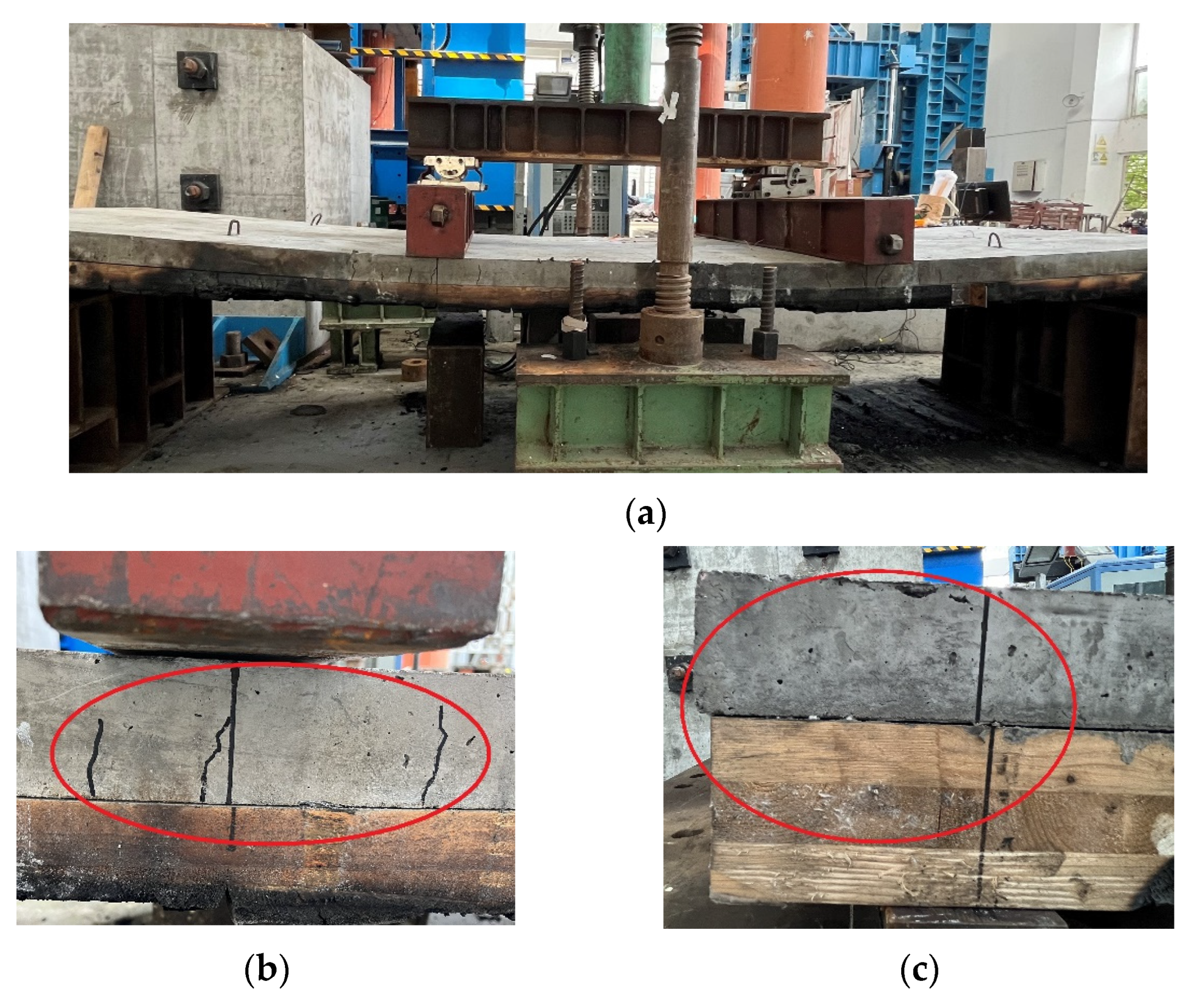
3.2. Residual Load-Carrying Capacity Tests after Fire

The failure modes of the three CLT–concrete composite board specimens were similar in the residual load-carrying capacity tests, as shown in Figure 12. The specimens were in an elastic state in the initial loading stage. When the load was about to reach the ultimate load, the interface between the screw thread and the CLT was destroyed. The interface between the CLT panel and the concrete board underwent a clear relative slip. As the applied loads increased, cracks appeared in the tensile zone of the concrete board centered on the loading point, and the length of these cracks continuously increased. After reaching the ultimate load, the load sharply dropped with increasing deflection, which can be interpreted as the failure of the CLT–concrete composite board specimens.
According to the test data, the load–deflection curves are presented in Figure 13. The TCC board specimen TCC1 reached an ultimate load of 52 kN, corresponding to a maximum deflection of 55.9 mm. The ultimate loads of specimens TCG2 and TCG3 were 71 and 73 kN, respectively. Compared with TCC1, the ultimate bearing capacity of TCG2 and TCG3 clearly increased (by 36.5% and 40.4%, respectively), indicating that this form of protection had a good fire-protective effect on the TCC board. If the coverage ratio was identical, a wider single gypsum board could slightly increase the residual carrying capacity. This result can be explained by the fact that the charred layer of all unprotected areas in specimens TCG2 and TCG3 completely developed to the second layer of the CLT panel; however, in specimen TCG2, the remaining amount of longitudinal timber of the CLT panel was less than that in specimen TCG3.

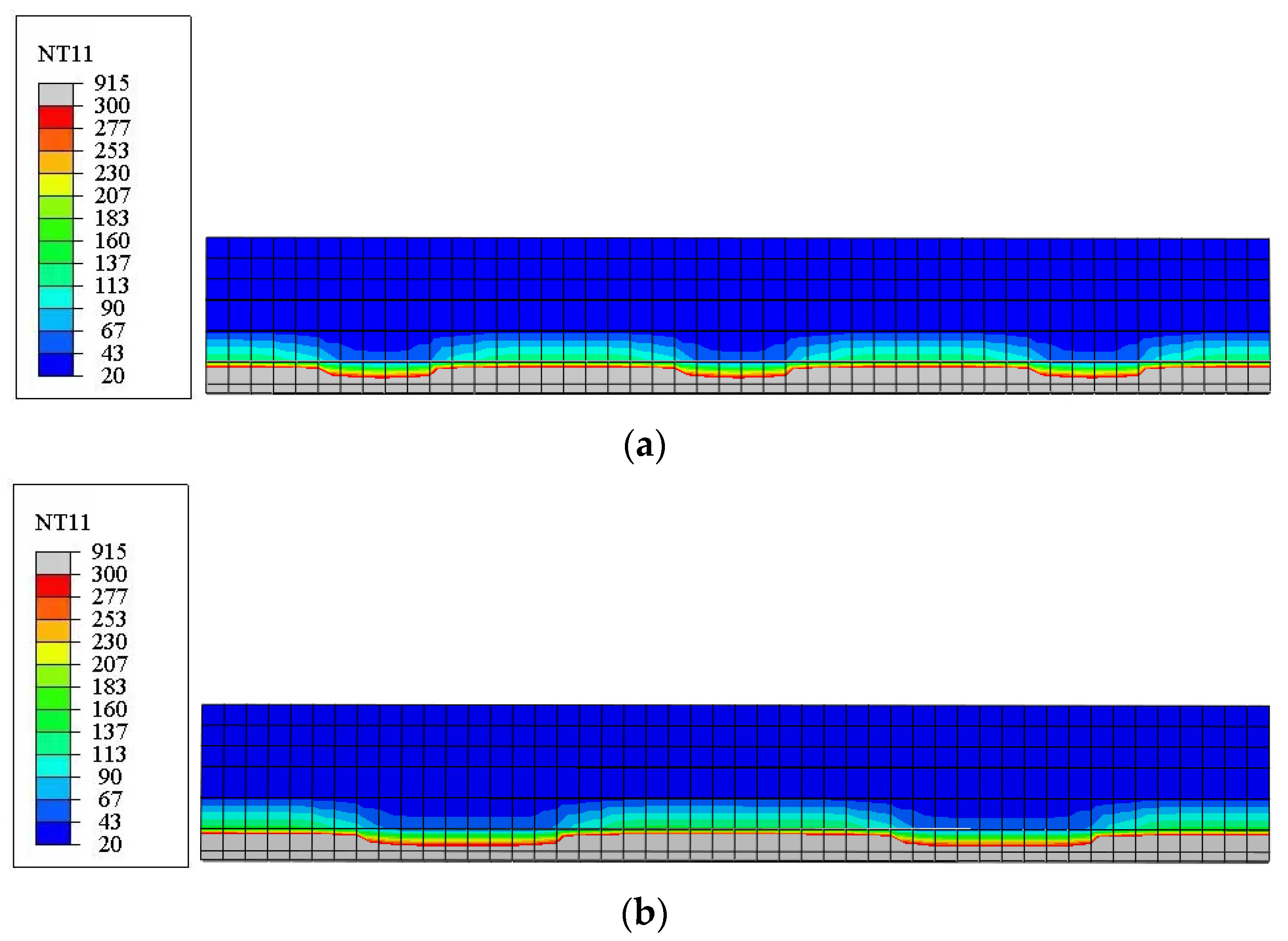
4. Finite Element Simulations

In this study, fire tests of CLT–concrete composite board specimens were first modelled using ABAQUS (v6.14) to investigate the temperature field of the specimens. In this part, the 3D, eight-node heat transfer element DC3D8 was utilized to simulate transient heat transfer, and the size of the element was meshed to approximately 25 mm after analyses. The main thermal properties of the concrete, timber, and gypsum board are the specific heat, thermal conductivity, and density, which play an important role in the temperature field distribution. These thermal properties of timber and concrete under standard fire exposure were determined from EN 1995-1-2 [22] and EN 1994-1-2 [34], respectively. The densities of the timber and the concrete used in the heat transfer models were 490 and 2500 kg/m3, respectively. These thermal properties of the gypsum board under standard fire exposure were provided by Keerthan [30]. The density of the gypsum board used in the heat transfer models was 900 kg/m3, provided by the supplier. Most of the tests state that when the protected face of the CLT reaches 600 °C, the directly applied Type X gypsum board will start falling off [26]. The finite element simulation was set according to this standard using the “model change” tool in ABAQUS.
According to the results of the tests and the results of Shephard [16], it was found that the temperature rise of the shear connectors was not obvious. Therefore, the heat transfer effect of the shear connectors was assumed to be neglected in the heat transfer models. The adhesive part demonstrated little influence on the numerical simulation, and the numerical model without the adhesive part agrees well with the results of tests, including both ambient tests and fire tests [34,35]. To simplify the numerical model, the adhesive part was not simulated. The concrete and timber were assumed to be isotropic materials in the heat transfer models, having the same thermal conductivity in all directions. The fire-exposed side of the models adopted a one-dimensional fire simulation following the ISO 834 standard heating curve. The convection coefficient was set as 25 W/(m2K) [22], and the emissivity of the timber was set as 0.8 [22]. A room temperature of 20 °C was set as the predefined temperature field for the models. The other boundary conditions were not set, and the transient heat transfer analysis step lasted 60 min.
The comparisons of the temperature test values and finite element values at each measuring point are shown in Figure 14. The temperature of the finite element result was slightly higher than the test result in the beginning; later, the finite element result was lower. This can be explained by the furnace temperature being below the standard curve at the beginning of the test and, as the duration of fire exposure increased, the crack sped up the heat transfer, increasing the temperature of the measuring point. The cross sections of the temperature distributions of specimen TCG2 and specimen TCG3 under 60 min of fire exposure are shown in Figure 15, and a critical temperature of 300 °C was set to evaluate the charred depth. The results of the comparison indicated that the thermal model established in this study demonstrates high applicability and can accurately simulate the change in temperature.
After the transient heat transfer analysis, a thermomechanical analysis was conducted to study the residual load-carrying capacity of the CLT–concrete composite board specimens following fire exposure. The final temperature field of the transient heat transfer models was set as the predefined temperature field for the models in this analysis. The mechanical properties of the timber were different from those at room temperature after being subjected to high temperature. Its mechanical properties can be fully restored to the initial level if it is heated to temperatures below 100 °C [36]. If the temperature exceeded 100 °C and was lower than 300 °C, its mechanical properties were reduced. The timber was assumed to be charred when the temperature reached 300 °C. Therefore, the reduction factors were assumed in the mechanical properties after being subjected to a high temperature. The reduction factor was set to one if the temperature was lower than 100 °C. The reduction factors were assumed to be in accordance with EN 1995-1-2 [22] when the temperature was between 100 and 300 °C. When the temperature was over 300 °C, the strength and MOE were taken to be 1/100 of their values at room temperature [37]. The initial density and elastic modulus of spruce are 490 kg/m3 and 11,000 MPa, respectively. The Poisson ratio of spruce is 0.48 [38].
By establishing local datum coordinate systems [39], the CLT (i.e., spruce) was simulated as an orthogonal configuration with different longitudinal layers and transverse layers with two material orientations. Engineering constants, e.g., elastic modulus, Poisson’s ratio, and shear modulus in three directions, were used to define the timber. The relationship between the elastic modulus and the shear modulus of timber was taken from EN 338 [40]. The orthotropic yield criterion and the input of six parameters in ABAQUS were defined as the plasticity of timber. The coefficients used to define the characteristics of timber were taken from the study by Dias [41].
It is known from the experimental results that 60 min of fire exposure has little influence on the temperature change of the concrete and shear connectors; therefore, the mechanical properties of the concrete and shear connectors were assumed to be the same as those at room temperature in this analysis. According to Eurocode 2 [31], the elastic modulus and the Poisson ratio of concrete were set as 30,000 MPa and 0.2, respectively. The compressive stress–strain curve of concrete is given in [41], and the compressive strength of concrete was 29.5 MPa, according to the results of the tests. It has been confirmed that it is feasible to replace solid shear connector elements with nonlinear spring elements [42]. In this analysis, nonlinear spring elements were used, and their parameters were determined according to the load–slip curves obtained from push-out tests and compiled in an input (INP) file. More details of the set of nonlinear spring elements can be found in the study by Bao et al. [8]. The adhesive part was not simulated as discussed above. Due to the gypsum board falling off after the fire tests, it was no longer simulated in this analysis. The 3D, eight-node, hexahedral, linear, reduced-integral element C3D8R was utilized in this simulation. The comparisons of the experimental and finite element results are shown in Figure 16, and the simulated results were consistent with the test results. The residual load-carrying capacity of the TCC board received from the finite element simulation was slightly higher than the test results. This may have occurred because the final finite element temperature result was lower than the test results, and natural defects were not simulated.

5. Conclusions

The improvement in the fire resistance of CLT–concrete composite boards with innovative partial protection was investigated by carrying out three full-scale fire tests and residual load-carrying capacity tests after fire exposure. In addition, finite element models of the CLT–concrete composite boards were established to determine the temperature field during fire exposure and the residual load-carrying capacity after the fire exposure of TCC boards. Based on the results of this study, the following main conclusions can be made:
  • In comparison to the TCC board without any protection, the fire resistance of the TCC board using a partial double, 12.7 mm thick Type X gypsum board protection was greatly improved. The unprotected area provided over 10 min of protection time, which is equivalent to the protection effect of a 9.5 mm thick gypsum board. The protected area provided a protection time of approximately 40 min. These conclusions can provide a reference for fire design in engineering;
  • For the TCC board with innovative partial protection, if the coverage ratio is identical, a wider single gypsum board can slightly increase the residual carrying capacity. After 60 min of fire exposure, the residual load-carrying capacity of the TCC board with 50% protection was approximately more than 35% higher than the capacity of the TCC board without any protection. The test results showed that this form of protection could effectively improve the fire resistance of CLT–concrete composite boards;
  • According to the results in this study, the maximum average temperature at the screw connectors was only 10 °C hotter than the timber in the same location at the end of the test. The shear connectors had a negligible impact on the heat transfer and the charring rate of the timber. When the CLT–concrete composite boards were exposed to fire, the timber can char and fall off, resulting in a charring rate higher than the reference value of 0.65 mm/min provided by the standard EN 1995-1-2. It is not conservative if used in the structural fire design of CLT–concrete composite boards. When an innovative form of partial protection is used, the start of timber charring is effectively delayed and the charring rate is reduced;
  • A numerical approach was established to investigate the temperature field during fire exposure and the residual load-carrying capacity after fire exposure of TCC boards. The comparison results clearly indicated that the numerical models demonstrated a high applicability and accuracy for temperature distribution during fire exposure and residual load-carrying capacity after fire exposure.

Author Contributions

H.Z.: methodology, investigation, writing—original draft, and software; W.L.: conceptualization, resources, supervision, project administration, and funding acquisition; Y.B.: validation and visualization; L.W.: data curation; B.L.: visualization; J.Z.: preparation for tests; Z.C.: preparation for tests. All authors have read and agreed to the published version of the manuscript.

Funding

This work was carried out as part of projects entitled “the General Project of National Natural Science Foundation of China” (51878345) and “Postgraduate Research & Practice Innovation Program of Jiangsu Province” (KYCX22_1330).

Institutional Review Board Statement

Not applicable.

Informed Consent Statement

Not applicable.

Data Availability Statement

No further data are available.

Acknowledgments

The authors wish to acknowledge the General Project of National Natural Science Foundation of China (Grant No. 51878345) and the Postgraduate Research & Practice Innovation Program of Jiangsu Province (No. KYCX22_1330).

Conflicts of Interest

The authors declare no conflict of interest.

References

  1. Pajchrowski, G.; Noskowiak, A.; Lewandowska, A.; Strykowski, W. Wood as a building material in the light of environmental assessment of full life cycle of four buildings. Constr. Build. Mater. 2014, 52, 428–436. [Google Scholar] [CrossRef]
  2. Brandner, R.; Flatscher, G.; Ringhofer, A.; Schickhofer, G.; Thiel, A. Cross laminated timber (CLT): Overview and development. Eur. J. Wood. Wood. Prod. 2016, 74, 331–351. [Google Scholar] [CrossRef]
  3. Barber, D. Determination of fire resistance ratings for glulam connectors within US high rise timber buildings. Fire Saf. J. 2017, 91, 579–585. [Google Scholar] [CrossRef]
  4. Yeoh, D.; Fragiacomo, M.; De Franceschi, M.; Boon, K.H. State of the art on timber-concrete composite structures: Literature review. J. Struct. Eng. 2011, 137, 1085–1095. [Google Scholar] [CrossRef]
  5. Xie, Z.; Hu, X.M.; Du, H.; Zhang, X.Y. Vibration behavior of timber-concrete composite floors under human-induced excitation. J. Build. Eng. 2020, 32, 101744. [Google Scholar] [CrossRef]
  6. Mai, K.Q.; Park, A.; Lee, K. Experimental and numerical performance of shear connections in CLT–concrete composite floor. Mater. Struct. 2018, 51, 84. [Google Scholar] [CrossRef]
  7. Mai, K.Q.; Park, A.; Nguyen, K.T.; Lee, K. Full-Scale Static and Dynamic Experiments of Hybrid CLT-Concrete Composite Floor. Constr. Build. Mater. 2018, 170, 55–65. [Google Scholar] [CrossRef]
  8. Bao, Y.W.; Lu, W.D.; Yue, K.; Zhou, H.; Lu, B.H.; Chen, Z.T. Structural performance of cross-laminated timber-concrete composite floors with inclined self-tapping screws bearing unidirectional tension-shear loads. J. Build. Eng. 2022, 55, 22. [Google Scholar] [CrossRef]
  9. Shi, B.K.; Zhu, W.X.; Yang, H.F.; Liu, W.Q.; Tao, H.T.; Ling, Z.B. Experimental and theoretical investigation of prefabricated timber-concrete composite beams with and without prestress. Eng. Struct. 2020, 204, 16. [Google Scholar] [CrossRef]
  10. Frangi, A.; Fontana, M.; Hugi, E.; Jobstl, R. Experimental analysis of cross-laminated timber panels in fire. Fire Saf. J. 2009, 44, 1078–1087. [Google Scholar] [CrossRef]
  11. Menis, A.; Fragiacomo, M.; Clemente, I. Fire resistance of unprotected cross-laminated timber floor panels: Parametric study and simplified design. Fire Saf. J. 2019, 107, 104–113. [Google Scholar] [CrossRef]
  12. Liu, J.; Fischer, E.C. Review of large-scale CLT compartment fire tests. Constr. Build. Mater. 2022, 318, 126099. [Google Scholar] [CrossRef]
  13. Osborne, L.; Sc, M.A. Fire Resistance of Long Span Composite Wood-Concrete Floor Systems; FPInnovations Project: Quebec, QC, Canada, 2015. [Google Scholar]
  14. Dagenais, C.; Ranger, L.; Auclair, S.C. Understanding fire performance of wood-concrete composite floor systems. In Proceedings of the World Conference on Timber Engineering, Vienna, Austria, 22–25 August 2016. [Google Scholar]
  15. Frangi, A.; Knobloch, M.; Fontana, M. Fire design of timber-concrete composite boards with screwed connections. J. Struct. Eng. 2014, 136, 219–228. [Google Scholar] [CrossRef]
  16. Shephard, A.B.; Fischer, E.C.; Barbosa, A.R. Fundamental behavior of timber concrete-composite floors in fire. J. Struct. Eng. 2021, 147, 04020340. [Google Scholar] [CrossRef]
  17. Du, H.; Hu, X.M.; Xie, Z.; Meng, Y.F. Experimental and analytical investigation on fire resistance of glulam-concrete composite beams. J. Build. Eng. 2021, 44, 103244. [Google Scholar] [CrossRef]
  18. Bedon, C.; Fragiacomo, M. Timber-concrete composite structures in fire conditions-Finite Element numerical modelling of tensile tests. In Proceedings of the Final Conference COST FP1404 “Fire Safe Use of Bio-Based Building Products”, Zurich, Switzerland, 2 October 2018. [Google Scholar]
  19. Muszynski, L.; Gupta, R.; Hong, S.H.; Osborn, N.; Pickett, B. Fire resistance of unprotected cross-laminated timber (CLT) floor assemblies produced in the USA. Fire Saf. J. 2019, 107, 126–136. [Google Scholar] [CrossRef]
  20. Hozjan, T.; Bedon, C.; Ogrin, A.; Cvetkovska, M.; Klippel, M. Literature review on timber–concrete composite structures in fire. J. Struct. Eng. 2019, 145, 04019142. [Google Scholar] [CrossRef]
  21. EN 1995-1-2; Eurocode 5: Design of Timber Structures, Part 1–2: General -Structural Fire Design. European Committee for Standardization: Brussels, Belgium, 2004.
  22. Kolaitis, D.I.; Asimakopoulou, E.K.; Founti, M.A. Fire protection of light and massive timber elements using gypsum plasterboards and wood based panels: A large-scale compartment fire test. Constr. Build. Mater. 2014, 73, 163–170. [Google Scholar] [CrossRef]
  23. Richardson, L.R.; Batista, M. Fire resistance of timber decking for heavy timber construction. Fire Mater. 2001, 25, 21–29. [Google Scholar] [CrossRef]
  24. White, R.H. Fire resistance of wood members with directly applied protection. In Proceedings of the Fire and Materials 2009: 11th International Conference and Exhibition, San Francisco, CA, USA, 26–28 January 2009. [Google Scholar]
  25. Osborne, L.; Dagenais, C.; Bénichou, N. Preliminary CLT Fire Resistance Testing Report; FPInnovations Project: Quebec, QC, Canada, 2012. [Google Scholar]
  26. Hasburgh, L.; Bourne, K.; Dagenais, C.; Ranger, L.; Roy-Poirier, A. Fire performance of mass-timber encapsulation methods and the effect of encapsulation on char rate of cross-laminated timber. In Proceedings of the World Conference on Timber Engineering, Vienna, Austria, 22–25 August 2016. [Google Scholar]
  27. ANSI/PRG320-2012; Standard for Performance-Rated Cross-Laminated Timber. Standardization Administration of the United States: New York, NY, USA, 2012.
  28. ISO 834-1; Fire-Resistance Tests-Elements of Building Construction-Part1: General Requirements. International Organization for Standardization: Geneve, Switzerland, 1999.
  29. GB/T 50329; Standard for Test Methods of Timber Structures. Standardization Administration of China: Beijing, China, 2012. (In Chinese)
  30. Keerthan, P.; Mahendran, M. Numerical studies of gypsum plasterboard panels under standard fire conditions. Fire Saf. J. 2012, 53, 105–119. [Google Scholar] [CrossRef] [Green Version]
  31. EN 1992-1-1; Eurocode 2: Design of Concrete Structures—Part 1: General Rules and Rules for Buildings. European Committee for Standardization: Brussels, Belgium, 2004.
  32. Maraveas, C.; Miamis, K.; Matthaiou, C.E.; Maraveas, C. Performance of timber connections exposed to fire: A review. Fire Technol. 2015, 51, 1401–1432. [Google Scholar] [CrossRef]
  33. Klippel, M.; Schmid, J. Design of cross-laminated timber in fire. Struct. Eng. Int. 2017, 27, 224–230. [Google Scholar] [CrossRef]
  34. Fragiacomo, M.; Menis, A.; Clemente, I.; Bochicchio, G.; Ceccotti, A. Fire resistance of cross-laminated timber panels loaded out of plane. J. Struct. Eng. 2013, 139, 04013018. [Google Scholar] [CrossRef]
  35. Audebert, M.; Dhima, D.; Taazount, M.; Bouchair, A. Behavior of dowelled and bolted steel-to-timber connections exposed to fire. Eng. Struct. 2012, 39, 116–125. [Google Scholar] [CrossRef]
  36. Gerhards, C.C. Effect of moisture-content and temperature on the mechanical-properties of wood—An analysis of immediate effects. Wood and Fiber. 1982, 14, 4–36. [Google Scholar]
  37. Fragiacomo, M.; Menis, A.; Moss, P.J.; Clemente, I.; Buchanan, A.H.; De Nicolo, B. Predicting the fire resistance of timber members loaded in tension. Fire Mater. 2013, 37, 114–129. [Google Scholar] [CrossRef]
  38. Chybinski, M.; Polus, L. Theoretical, experimental and numerical study of aluminium-timber composite beams with screwed connections. Constr. Build. Mater. 2019, 226, 317–330. [Google Scholar] [CrossRef]
  39. Wang, Y.X.; Zhang, J.; Mei, F.; Liao, J.N.; Li, W.B. Experimental and numerical analysis on fire behaviour of loaded cross-laminated timber panels. Adv. Struct. Eng. 2020, 23, 22–36. [Google Scholar] [CrossRef]
  40. EN 338-2016; Structural Timber—Strength Classes. European Committee for Standardization: Brussels, Belgium, 2015.
  41. Dias, A.; Van de Kullen, J.W.; Lopes, S.; Cruz, H. A non-linear 3D FEM model to simulate timber–concrete joints. Adv. Eng. Softw. 2007, 38, 522–530. [Google Scholar] [CrossRef]
  42. Lopes, S.; Jorge, L.; Cruz, H. Evaluation of non-linear behavior of timber–concrete composite structures using FE model. Mater. Struct. 2012, 45, 653–662. [Google Scholar] [CrossRef]
Figure 1. The arrangement of CLT–concrete composite board and distribution of screw connectors (units: mm).
Buildings 13 00725 g001
Figure 2. The forms of protection: (a) schematic diagram of TCG2; (b) photo of TCG2; (c) schematic diagram of TCG3; and (d) photo of TCG3 (units: mm).
Buildings 13 00725 g002
Figure 3. (a) Schematics of push-out tests (units: mm) and (b) the photograph of the push-out test system (Reproduced with permission from Ref. [8]. Copyright 2022 Elsevier.).
Buildings 13 00725 g003
Figure 4. (a) Fire test setup (units: mm) and (b) the photograph of TCC1 and TCG2 being tested together.
Buildings 13 00725 g004
Figure 5. Location of the thermocouples: (a) TCC1; (b) TCG2; (c) TCG3; and (d) the depths of the thermocouples (units: mm).
Buildings 13 00725 g005aBuildings 13 00725 g005b
Figure 6. Residual load-carrying capacity test setup (units: mm).
Buildings 13 00725 g006
Figure 7. (a) Appearance of TCC1 after extinguishing; (b) TCG2 being lifted out; and (c) TCG3 being lifted out.
Buildings 13 00725 g007
Figure 8. Furnace temperature-rising curves.
Buildings 13 00725 g008
Figure 9. Temperature–time curves of the TCC boards under fire: (a) TCC1; (b) TCG2; and (c) TCG3.
Buildings 13 00725 g009
Figure 10. Temperature–time curves of the measuring points under fire: (a) 10 mm; and (b) 35 mm.
Buildings 13 00725 g010
Figure 11. The residual cross sections of the CLT panel after tests: (a) TCC1; (b) TCG2; and (c) TCG3.
Buildings 13 00725 g011
Figure 12. (a) Bending deformation in the elastic stage; (b) vertical crack in the concrete; and (c) interfacial relative slip.
Buildings 13 00725 g012
Figure 13. Load-deflection curves of composite boards.
Buildings 13 00725 g013
Figure 14. Comparison of the temperature test values and finite element values: (a) TCC1; (b) TCG2; and (c) TCG3.
Buildings 13 00725 g014
Figure 15. The cross section of temperature distributions: (a) TCG2; and (b) TCG3.
Buildings 13 00725 g015
Figure 16. Comparison of experimental and finite element results of the load–deflection curves.
Buildings 13 00725 g016
Table 1. Main parameters of composite board specimens.
Test SpecimensProtection MaterialWidth of Single Protected Area (mm)Coverage Ratio
TCC1---
TCG2Double 12.7 mm thick Type X gypsum boards20050%
TCG330050%
Note: The coverage ratio is equal to the area of the gypsum boards divided by the area of direct fire action.
Table 2. Charred depth and the average charring rate.
Test SpecimensMeasurement AreaResidual Height (mm)Charred Depth (mm)Charring Rate (mm/min)
TCC1-62.0942.910.74
TCG2Unprotected68.8635.140.59
Protected83.5021.500.36
TCG3Unprotected68.2935.710.60
Protected84.8820.120.34
Table 3. Protection times.
Test SpecimensMeasurement AreaCharred Time (min)Protection Time (min)
TCC1-13-
TCG2Unprotected2613
Protected5340
TCG3Unprotected2411
Protected5542
Note: Charred time is the time at which the measuring points 10 mm from the fire-exposed side reached 300 °C.
Disclaimer/Publisher’s Note: The statements, opinions and data contained in all publications are solely those of the individual author(s) and contributor(s) and not of MDPI and/or the editor(s). MDPI and/or the editor(s) disclaim responsibility for any injury to people or property resulting from any ideas, methods, instructions or products referred to in the content.

