Article

Dynamic Properties of Timber–Concrete Composite Beams with Crossed Inclined Coach Screw Connections: Experimental and Theoretical Investigations

1
College of Civil Engineering, Nanjing Tech University, Nanjing 211816, China
2
College of Architecture, Sanjiang University, Nanjing 210012, China
3
School of Civil Engineering, Southeast University, Nanjing 211189, China
*
Author to whom correspondence should be addressed.
Buildings 2023, 13(9), 2268; https://doi.org/10.3390/buildings13092268
Submission received: 29 June 2023 / Revised: 29 August 2023 / Accepted: 4 September 2023 / Published: 6 September 2023
(This article belongs to the Special Issue Timber, Bamboo and Hybrid Structures)

Abstract

:
Due to the low density and stiffness of wood, traditional timber floor systems are prone to producing large vibration responses. By combining timber beams with concrete floors, timber–concrete composite (TCC) floor systems show stronger bearing capacity, higher bending stiffness, and better thermal and sound insulation behaviors when compared with traditional timber floor systems. In this study, the vibration performance of TCC beams with crossed inclined coach screw connectors was investigated using dynamic tests. The influence of the screw diameters and slab dimensions on the dynamic performance of the composite beams was evaluated. The test results demonstrated that TCC beams show good dynamic performance when used as a floor component and meet the preliminary requirements of floor vibration comfort for fundamental frequency. The fundamental frequency and damping ratio of TCC beams decreases with the increase in slab dimensions. The bending stiffness and natural frequency of TCC beams decrease smoothly when reducing the screw diameter from 16 to 12 mm. Additionally, two theoretical models were used to predict the natural frequencies of the TCC beams, and the predicted values show good consistency with the measured ones.

1. Introduction

Timber members, characterized by light mass and high strength, are easily fabricated and assembled in construction [1,2,3]. However, compared to concrete or steel, timber shows apparent disadvantages in density and modulus of elasticity. Timber floors easily produce annoying vibrations, which affect the comfort of users, and even cause resonance that endangers the safety of the structure. Therefore, scholars have focused on the vibration problem of timber floors since the 1970s, forming a series of design methods and controlling indicators [4,5]. The controlling vibration factors include deformation modal parameters and excitation responses, such as deflection d, fundamental frequency f, speed v, and acceleration a, under dynamic load [6,7,8,9,10].
Existing investigations found that adding concrete to timber beams can significantly improve the vibration performance of the floor system. Compared to pure timber floors, timber–concrete composite (TCC) floors show significant improvement in the sound insulation effect and in reducing the sensitivity of vibration comfort, by means of increasing the stiffness of the components through the composite action [11,12,13].
Studies on TCC structures are mainly focused on static properties, but there are limited studies on vibration behavior. Deam et al. [14] experimentally investigated the dynamic performance of laminated veneer lumber (LVL)–concrete composite beams. Their study showed that the concrete slab is beneficial in reducing fundamental frequency and acceleration sensitivity when compared with pure timber floors, which can effectively avoid the sensitive perception range of people. Mertens et al. [15] conducted dynamic tests both on timber floors and TCC floors and evaluated vibration comfort according to the European standard EN 1995-1-1 (Eurocode 5) [10]. They found that TCC floors could meet the requirements of fundamental frequency and that TCC connections are crucial to the vibration response of TCC floors. Rijal et al. [16] discussed the influences of different connection types on the dynamic performances of TCC beams. Through experimental research, they found that different shear connectors influence beams’ natural frequencies and damping ratios.
The interlayer connection is a crucial aspect of research in timber–concrete composite structures. Various types of fasteners have been reported for TCC structures. Chybiński and Polus [17] developed an aluminum–timber composite connection with hexagonal head wood screws and reinforced with toothed plates. Through an experimental study, it was found that bearing strength can be significantly improved after strengthening with a toothed plate. Lukaszewska et al. [18] developed a novel composite floor system by connecting prefabricated concrete slabs to timber joists. They developed and tested various types of shear connectors for the floor system, including metal plates, dowels, toothed metal plates, and hexagonal head wood screws with steel tubes. Through experiments and numerical analysis, they found that the connections all have good structural performance, especially the coach screws and notch connections. Szumigała et al. [19] developed new connectors for timber–concrete composite structures, consisting of a headed stud and a steel screw. Through experiments and analyses, it was found that the significant advantage of the new connection is ductility. Tao et al. [20,21] studied the feasibility of glued perforated steel plates in prefabricated timber–concrete composite structures. Their results showed that the glued perforated steel plate connections have high slip stiffness and shearing capacity. Gutkowski et al. [22] studied a composite concrete–wood floor system using a novel notched shear key/anchor connection. Their results indicated its structural merit compared with ordinary mechanical connectors.
In this study, connections with crossed inclined coach screws were used for TCC beams considering their high construction efficiency and good shear performance [23]. Wen et al. [24] investigated the vibration performance of timber–lightweight aggregate concrete composite beams using three different connection methods. Among them, the natural frequency of composite beams connected with crossed inclined screw connections is lower than those with notch-screw connections or glued-steel plate connections. There are limited studies available in the literature on the dynamic performance of TCC beams with crossed inclined coach screw connections. Therefore, this study aimed to investigate the dynamic properties of TCC beams that utilize crossed inclined coach screws. Experimental investigations were conducted to evaluate the modal dynamic properties of TCC beams, including their fundamental frequency and damping ratio. Moreover, the effects of concrete slab dimensions and screw diameter on the dynamic performance of TCC beams are discussed.

2. Materials and Methods

2.1. Materials

2.1.1. Timber

The glulam beams were made with Douglas fir lumber from North America. The lumber has a density of 456 kg/m3 and a moisture content of 11.2%. Their moisture content was determined using tests according to GB/T 1931-2009 [25], and their density was measured following the GB/T 1933-2009 [26] guidelines. For the tests, a drying oven with machine model DHG-9140(A) (101-2), produced by Yiheng Scientific Instrument Co., LTD., Shanghai, China, was used. The basic mechanical properties of glulam were obtained using material tests according to EN 408 [27]. The dimensions of the samples used in the tensile, compressive, and shear tests were 30 mm × 10 mm × 300 mm (height × width × length), 50 mm × 50 mm × 300 mm, and 55 mm × 32 mm × 300 mm, respectively. A testing machine produced by MTS System (China) Co., Ltd. (Shanghai, China) with a maximum capacity of 300 kN, was used for the material tests. The corresponding test results are shown in Table 1.

2.1.2. Concrete

The concrete slabs were poured with C40 grade cast in situ concrete. The compression tests were conducted on the concrete cubes with a side length of 150 mm under natural curing for 28 days. The Young’s modulus and the tensile strength of the concrete were obtained via tests according to GB50010-2010 [28]. The tests were conducted using a Microcomputer-controlled automatic pressure tester produced by Sansi Instrument Manufacturing Co., Ltd. (Shanghai, China). The basic mechanical properties of the concrete are shown in Table 2.

2.1.3. Steel

The steels used in this test mainly include the reinforcing bars, bearing supports, and coach screws. The strength grade of the steel made for the reinforcing bars and coach screws was S355 with a yield strength of 345 MPa and a modulus of elasticity of 200 GPa. The bearing supports were manufactured with high strength steel with a yield strength of 640 MPa and a modulus of elasticity of 210 GPa. The diameter of the reinforcing bars was 8 mm at a spacing of 150 mm. The thickness of the bearing support plate was 30 mm. Coach screws with diameters of 12 mm or 16 mm and a length of 200 mm were used as the timber–concrete interfacial connections, as shown in Figure 1.

2.2. Specimens

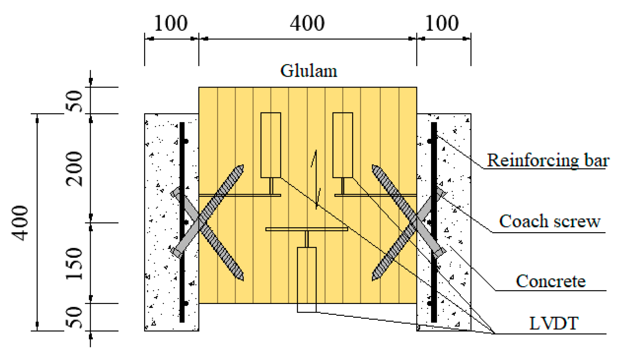
2.2.1. Shear Connectors

To evaluate the shear performance of the crossed inclined coach screws, the push-out tests were carried out in preliminary tests according to EN26891 [29]. Two groups of specimens with 3 samples in each group were analyzed in this study by adopting screws with different diameters. The specimens with 16 mm diameter screws were named CBIS16-200 and those with 12 mm diameter screws were named CBIS12-200. The length of the screws was 200 mm and the inclined angle was 45°. The test sample is shown in Figure 2. The predrilling diameter for CBIS16-200 was 12 mm, while that for CBIS12-200 was 9 mm. The screws were inserted using an electric wrench with a maximum torque moment of 200 N·m. A multifunctional testing device with a maximum load capacity of 250 kN produced by Hangzhou POPWIL electromechanical control engineering co., ltd., China was used for the test. The test setup for the push-out test is shown in Figure 3.

2.2.2. Timber–Concrete Composite (TCC) Beams
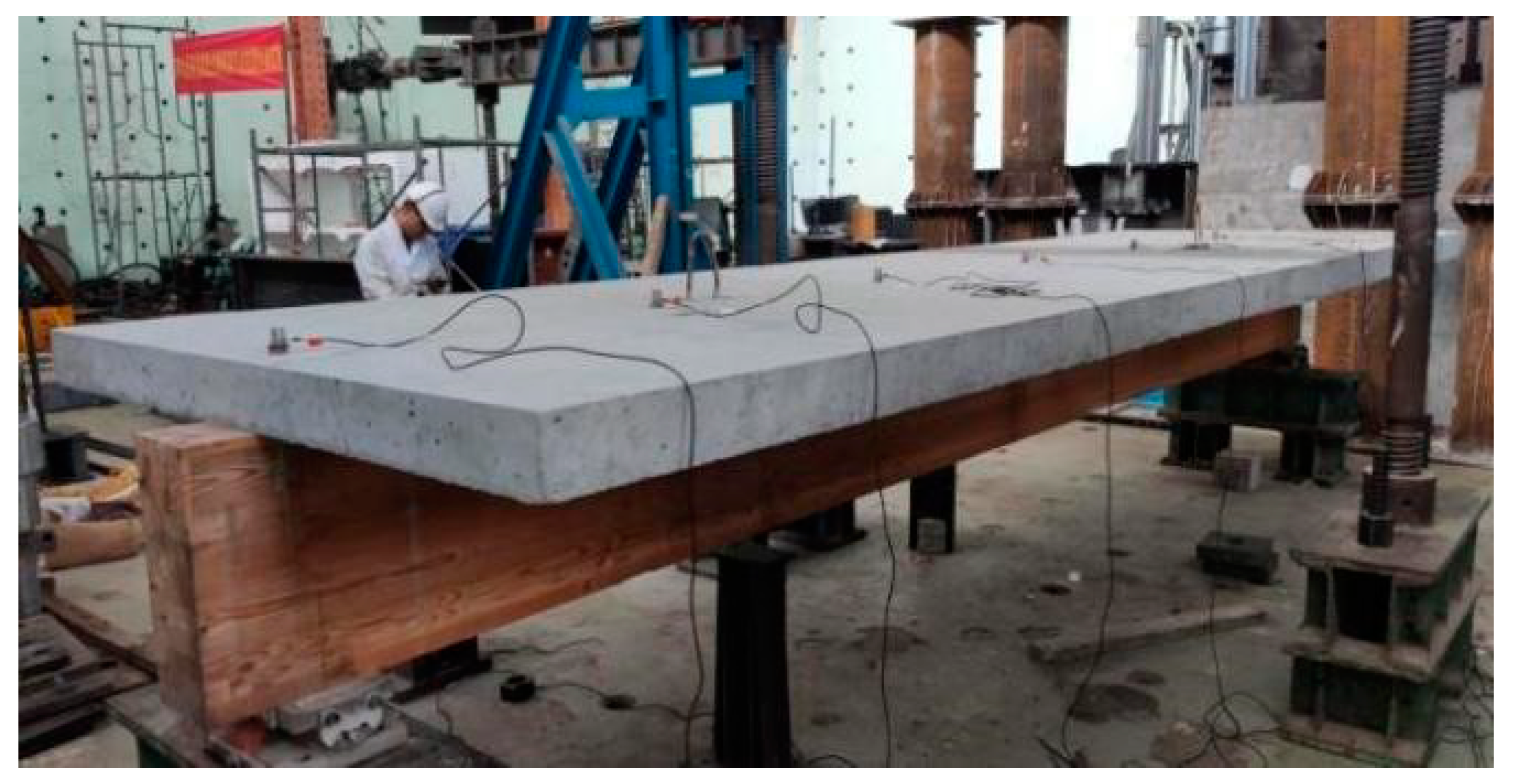
To evaluate the effects of concrete slab dimensions and screw diameter on the dynamic performance of the TCC beams, five TCC beam specimens were designed. The dimensions of the timber beams were 5000 mm × 150 mm × 400 mm (length × width × height), and the dimensions of the concrete slabs were 4800 mm in length with different widths and heights.
To explore the influence of concrete slab width on vibration performance, three slab widths of 930 mm, 1395 mm, and 1860 mm were designed under the clear span of 4650 mm. The parameter bc/l is the width-to-span ratio, which was 0.2, 0.3, and 0.4 in this study. Therefore, the TCC beams were named after bc/l, which are TCC0.2, TCC0.3, and TCC0.4, respectively. Also, this study tested two different concrete slab heights, 100 mm and 120 mm. The TCC beam with a 100 mm high concrete slab was designated as TCC0.4; while the TCC beam with a 120 mm thick concrete slab was specified as TCC0.4-hc120.
The timber beams and the concrete slabs were connected with crossed inclined coach screws. The test explored two sizes of coach screws, the beam with 12 mm diameter screws was named TCC0.4-CO12, and the others were all 16 mm. The spacing between the connectors was 300 mm in length of beam and 70 mm in width. The details of the parameters of the TCC beams are listed in Table 3, and an example of the TCC beam is shown in Figure 4.

2.3. Test Set-Up

All of the TCC beam specimens were tested under the same boundary conditions, with one hinge support at one end and a roller support at the other end, as shown in Figure 5. The specimens were placed in the central line of the supports, and the clear span of all beams was 4650 mm.

2.4. Equipment and Experimental Procedure

Acceleration sensors were arranged equidistantly along the central line of the upper surface of the concrete slabs, as shown in Figure 6 and Figure 7. The dynamic test was stimulated using a pulsed hammer. The response signal was collected using the dynamic signal test system TST3828E, and the modal analysis of dynamic properties was performed using the signal processing software DASP-V11. To improve the accuracy and reliability of the data, each TCC beam was tested twice, and the dynamic properties were determined using the average values from the two tests.
The TCC beams were tested under bending load, and the test set-up is shown in Figure 8 and Figure 9. The testing equipment comprises a hydraulic jack and a load cell produced by OVM Machinery Co., Ltd. in Liuzhou, China and Jiangsu Guo Yan Li Zhun Detection Instrument Technology Co., Ltd. in Nanjing, China, respectively. The hydraulic jack with counter-force frames provided the load, and the values of the applied forces were recorded with the load cell. The deflections of the TCC beans were recorded with linear variable displacement transducers (LVDTs).

3. Experimental Results

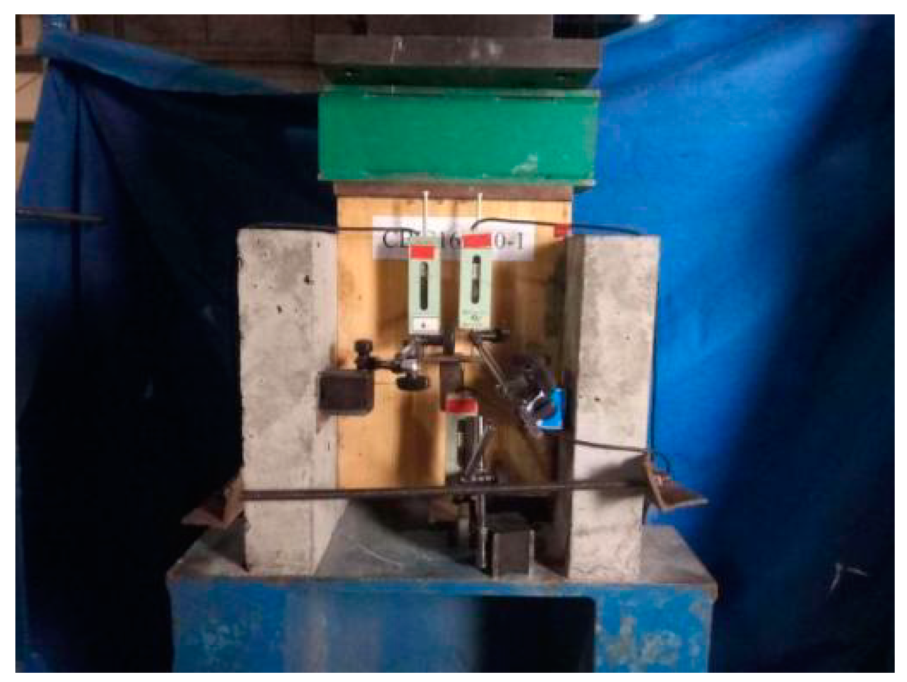
3.1. Push-Out Test of Connectors

According to the European standard EN26891 [29], the load, interfacial slip, and the slip stiffness of the connector were obtained. The shear properties of the connections are listed in Table 4.

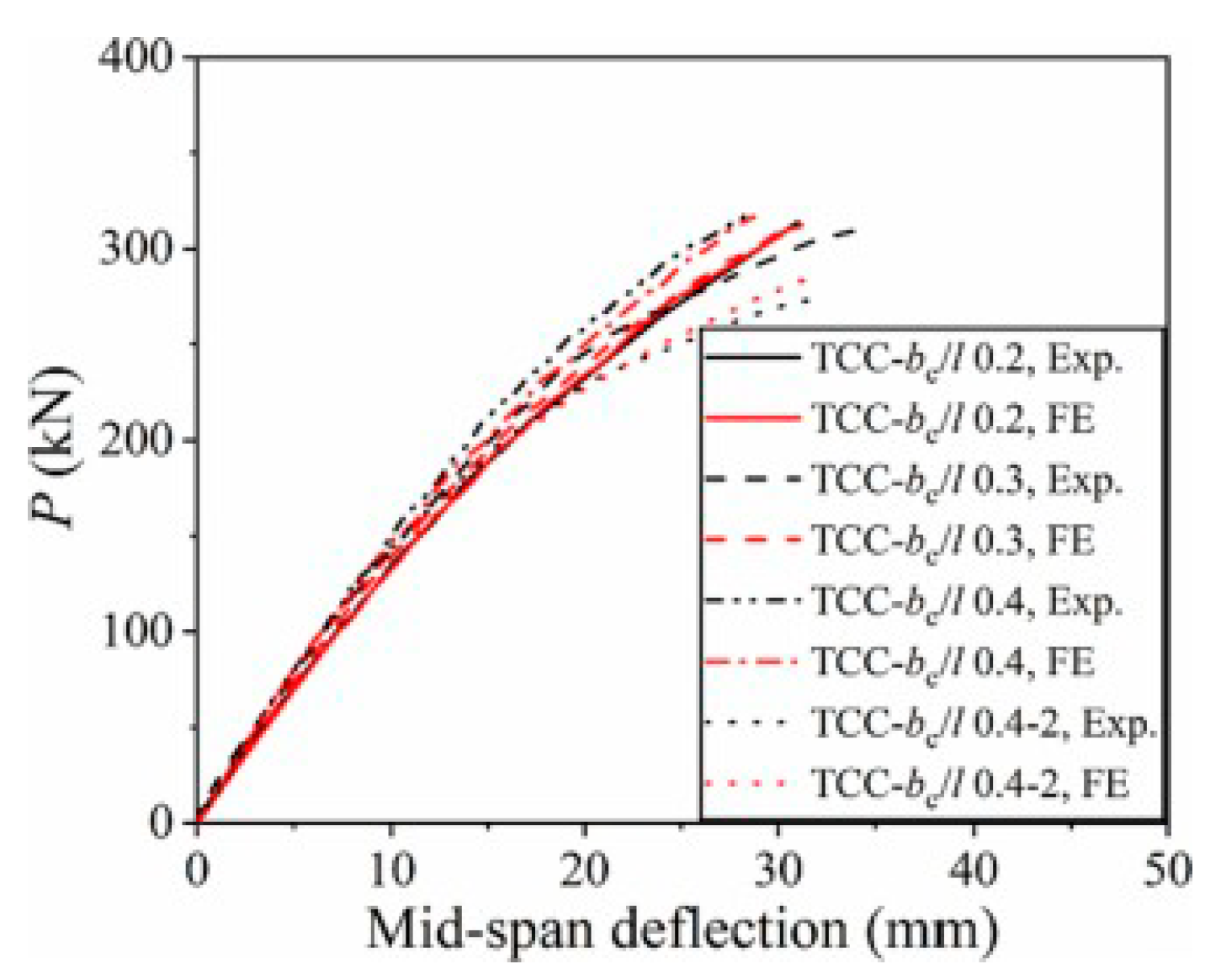
3.2. Dynamic and Bending Test of the TCC Beams

The TCC beams were stimulated with a hammer, and the time domain signals of acceleration responses (as shown in Figure 10) were collected from sensors. The time domain signals were subjected to fast Fourier transform (FFT); then, the natural frequencies (as shown in Figure 11) and damping ratio of the TCC beams could be calculated. The symbol f1(exp) denotes the measured values of fundamental frequencies of the first flexural modal, and ζ1 was used to indicate the first modal damping ratio of the TCC beams. The specific test results are listed in Table 5.
The load (P) was applied at the rate of 20 kN/min using a hydraulic jack with counterforce frames. The deflections were recorded via the LVDTs, and the load–deflection curves are shown in Figure 12. The bending properties at the serviceability state of the TCC beams are also listed in Table 5, including the mid-span deflection d and the bending stiffness (EI)(exp). The beams were tested to the ultimate load; Pu is the ultimate load and presents the failure mode, as shown in Figure 13.

4. Analytical Investigation

Studies have shown that people are most likely to feel uncomfortable when the floor is characterized by low-frequency vibrations, especially for frequencies in the range of 4–8 Hz [31]. Combined with research and ISO standards [32,33], scholars have given relevant indicators to control the vibration of timber floors for comfort. An important one of which is that the fundamental frequency (f1) should be greater than 8 Hz. If f1 is lower than 8 Hz, it is easy to cause discomfort to the users, and even footfall will cause resonance of the floor, causing safety problems [6,7,32,33]. For example, Eurocode 5 [10] stipulates that the f1 should be greater than 8 Hz. If the f1 of the floor is estimated to be lower than 8 Hz, special analysis and design should be carried out. As one of the important indicators of the dynamic properties of the floor, the fundamental frequency is an important indicator to evaluate whether the vibration performance of the floor is good. Therefore, the analysis of the f1 of the TCC beam is an important task of this study.

4.1. Theoretical Calculation

Eurocode 5 provides a calculation model for estimating the fundamental frequency (f1) of the floor system, as shown in Formula (1):
f 1 = π 2 l 2 E I m
where EI is the bending stiffness of the TCC beam; l is the span of the TCC beam; and m is the unit length mass of the TCC beam, including the beam self-weight and other permanent loads. In addition, the bending stiffness of the partially composite beams uses the effective bending stiffness (EI)eff, which is based on the ‘γ-method’, as shown in Formula (2):
( E I ) e f f = E c I c + E t I t + γ E c A c a c 2 + E t A t a t 2
γ = 1 1 + π 2 E c A c s K L 2
where the subscripts c and t designate the concrete and timber, respectively; E is the modulus of elasticity; I is the moment of inertia; γ is the reduction coefficient for the combined action; Ac and At are the section area of concrete slab and timber beam, respectively; ac and at are the distance between the centroid of concrete slab or timber beam to the neutral axis of the composite section, respectively; s is the distance of shear connectors; K is the slip stiffness of shear connections; and L is the clear span of beams.
Murray [34] also provides a calculation model that could estimate the fundamental frequency (f1) of the simply supported beams, as shown in Formula (4):
f 1 = π 2 g E I w L 4
where g is the acceleration of gravity; EI is the bending stiffness of the TCC beam; L is the clear span of the beam; and w is the uniformly distributed load in unit length.
The parameters adopted in the theoretical calculation are shown in the previous text. It is worth noting that Table 4 shows the shear properties of the connectors. Ks and Ku are the slip moduli of the connector at the serviceability limit and the ultimate state, respectively. When studying the vibration behavior of beams, the values of Ks were used to calculate the (EI)eff of TCC beams in the serviceability limit state. Using the Eurocode 5 and Murray methods, the semi-theoretical predicted values f1(EC5) and f1(M) of the fundamental frequencies of the TCC beams can be obtained, respectively, as shown in Table 6. Additionally, Tao et al. [23] have provided a theoretical calculation method of connector stiffness. Based on the connection stiffness calculation method, the full-theoretical predicted values of the fundamental frequencies can be obtained, as the values of f1(EC5) and f1(M) shown in Table 6.

4.2. Discussion

4.2.1. Fundamental Frequency

As shown in Table 6, the fundamental frequencies of the five composite beams ranged from 18 Hz to 26 Hz. If the TCC beams are considered as one-way floors, the control requirements of f1 > 8 Hz for the floor can be satisfied. From the comparison between the measured values and the calculated values, the value of the maximum difference between experimental frequency and full calculated frequency is 2.13 Hz, it can be seen that the calculation methods in the Eurocode 5 and Murray methods have good reliability.

4.2.2. Effect of the Dimensions of Concrete Slabs

From the data in Table 6, as the width of the slab increases, the flexural stiffness (EI)eff and (EI)(exp) of TCC beams increases, while the fundamental frequency decreases both in the calculated value and in the measured value. According to Equation (1), although the stiffness of the concrete slab increases with the increase in the slab width, the increase in self-weight caused by the increase in slab width still reduces the fundamental frequency of the TCC beams. Similarly, when the slab heights of the concrete are increased from 100 mm to 120 mm, the flexural stiffness (EI)eff of the TCC beam also increases significantly, but its fundamental frequency still decreases. Therefore, it can be preliminarily identified that the self-weight of concrete slab changes, caused by the dimension change, has a greater effect on the fundamental frequency of the TCC beams than the flexural stiffness (EI)eff, and the values of fundamental frequency using the Murray method have a similar pattern. In addition, the damping ratio decreases significantly as the width and height size of the concrete slab increase.

4.2.3. Effect of the Connection

This study tested two different connectors for the TCC beams. It can be seen in Table 4 and Table 6 that the flexural stiffness (EI)eff and (EI)(exp) of the TCC beam decreases when reducing the shear stiffness of the connectors. Meanwhile, when changing the screw diameter from 16 mm to 12 mm, the fundamental frequency of the TCC beams decreases smoothly, but the damping ratio increases notably, according to Table 6. This indicates that under the same conditions, the natural frequency of the specimen is inversely proportional to the damping ratio.

5. Conclusions

In this study, five TCC beams with a clear span of 4650 mm were tested under dynamic excitation. The vibration behavior of the TCC beams was evaluated based on the fundamental frequency and damping ratio. The fundamental frequency of the TCC beams was predicted and calculated using the calculation models in Eurocode 5 and the Murray method, respectively. The calculated values and the experimental values were compared and discussed. The generalized conclusions are as follows:
The TCC beams in this study can be used as the one-way floor unit and meet the requirement of f1 > 8 Hz for floor comfort.
The increase in the dimensions of the concrete slab can increase the flexural stiffness of the TCC beams, but the consequent increase in the self-weight of concrete causes a reduction in the fundamental frequency. The fundamental frequency of the composite beams decreases with the decrease in the connection shear stiffness, while the damping ratio increases with the reduction in the connection stiffness.
Both the methods provided by Eurocode 5 [10] and Murray [34] have certain reliability in predicting the vibration behavior of the TCC beams, but their calculation values are smaller than the experimental values. Therefore, a more in-depth study needs to be conducted, and our next research plan will try to optimize the existing predictive method.

Author Contributions

B.W.: methodology, investigation, writing—original draft preparation, funding acquisition; H.Y.: conceptualization, supervision, project administration, and funding acquisition, H.T.: visualization, test, writing—review and editing; B.S.: validation, writing—review and editing. All authors have read and agreed to the published version of the manuscript.

Funding

This research was funded by the General Project of National Natural Science Foundation of China, grant number 51878344; the Natural Science Foundation of the Jiangsu Higher Education Institutions of China, grant number 20KJB560002; the Science and Technology Project of Construction System of Jiangsu Province, grant number 2019ZD001205.

Data Availability Statement

No further data are available.

Conflicts of Interest

The authors declare no conflict of interest.

References

  1. Ramage, M.H.; Burridge, H.; Busse-Wicher, M.; Fereday, G.; Reynolds, T.; Shah, D.U.; Wu, G.; Yu, L.; Fleming, P.; Densley-Tingley, D.; et al. The wood from the trees: The use of timber in construction. Renew. Sust. Energ. Rev. 2017, 68, 333–359. [Google Scholar] [CrossRef]
  2. Asif, M. Sustainability of timber, wood and bamboo in construction. In Sustainability of Construction Materials; Jamal, K., Ed.; Woodhead Publishing Limited: Abington Hall, Granta Park, Great Abington, Cambridge, UK, 2009; pp. 31–54. [Google Scholar]
  3. Hafner, A.; Schäfer, S. Environmental aspects of material efficiency versus carbon storage in timber buildings. Eur. J. Wood Prod. 2018, 76, 1045–1059. [Google Scholar] [CrossRef]
  4. Weckendorf, J.; Toratti, T.; Smith, I.; Tannert, T. Vibration serviceability performance of timber floors. Eur. J. Wood Prod. 2016, 74, 353–367. [Google Scholar] [CrossRef]
  5. Ussher, E.; Arjomandi, K.; Smith, I. Status of vibration serviceability design methods for lightweight timber floors. J. Build. Eng. 2022, 50, 104–111. [Google Scholar] [CrossRef]
  6. Onysko, D.M. Serviceability Criterion for Residential Floors Based on a Field Study of Consumer Response; Project No. 03-50-10-008; Canadian Forestry Service (CFS): Ottawa, ON, Canada, 1985. [Google Scholar]
  7. Smith, I.; Chui, Y.H. Design of lightweight wooden floors to avoid human discomfort. Can. J. Civil. Eng. 1988, 15, 254–262. [Google Scholar] [CrossRef]
  8. Ohlsson, S. Ten years of floor vibration research: A review of aspects and some results. In Proceedings of the Symposium/Workshop on Serviceability of Buildings (Movements, Deformations, Vibrations), Ottawa, ON, Canada, 16–18 May 1988; pp. 435–450. [Google Scholar]
  9. National Building Code of Canada 2015; National Research Council (NRC), Institute for Research in Construction: Ottawa, ON, Canada, 2015.
  10. EN 1995-1-1:2009; Eurocode 5: Design of Timber Structures—Part 1-1: General-Common Rules and Rules for Buildings. European Committee for Standardization (CEN): Brussels, Belgium, 2009.
  11. Skinner, J.; Martins, C.; Bregulla, J.; Harris, R.; Paine, K.; Walker, P.; Dias, A.M.P.G. Concrete upgrade to improve the vibration response of timber floors. Str. B 2014, 167, 559–568. [Google Scholar] [CrossRef]
  12. Natterer, J.; Hamm, J.; Favre, P. Composite wood-concrete floors for multi-story buildings. In Proceedings of the International Wood Engineering Conference, New Orleans, LA, USA, 28–31 October 1996; pp. 3.431–3.435. [Google Scholar]
  13. Perković, N.; Rajčić, V.; Barbalić, J. Analytical and Numerical Verification of Vibration Design in Timber Concrete Composite Floors. Forests 2021, 12, 707. [Google Scholar] [CrossRef]
  14. Deam, B.L.; Fragiacomo, M.; Gross, L.S. Experimental behavior of prestressed LVL-concrete composite beams. J. Struct. Eng. 2008, 134, 801–809. [Google Scholar] [CrossRef]
  15. Mertens, C.; Martin, Y.; Dobbels, F. Investigation of the vibration behaviour of timber-concrete composite floors as part of a performance evaluation for the Belgian Building Industry. Build. Acoust. 2007, 14, 25–36. [Google Scholar] [CrossRef]
  16. Rijal, R.; Samali, B.; Shrestha, R.; Crews, K. Experimental and analytical study on dynamic performance of timber-concrete composite beams. Constr. Build. Mater. 2015, 75, 46–53. [Google Scholar] [CrossRef]
  17. Chybiński, M.; Polus, Ł. Mechanical behaviour of aluminium-timber composite connections with screws and toothed Plates. Materials 2022, 15, 68. [Google Scholar] [CrossRef] [PubMed]
  18. Lukaszewska, E.; Fragiacomo, M.; Johnsson, H. Laboratory tests and numerical analyses of prefabricated timber-concrete composite floors. J. Struct. Eng. 2009, 136, 46–55. [Google Scholar] [CrossRef]
  19. Szumigała, M.; Szumigała, E.; Polus, Ł. Laboratory tests of new connectors for timber-concrete composite structures. Eng. Trans. 2018, 66, 161–173. [Google Scholar]
  20. Tao, H.; Shi, B.; Yang, H.; Wang, C.; Ling, X.; Xu, J. Experimental and finite element studies of prefabricated timber-concrete composite structures with glued perforated steel plate connections. Eng. Struct. 2022, 268, 114778. [Google Scholar] [CrossRef]
  21. Yang, H.; Lu, Y.; Ling, X.; Tao, H.; Shi, B. Experimental and theoretical investigation on shear performances of glued-in perforated steel plate connections for prefabricated timber–concrete composite beams. Case Stud. Constr. Mater. 2023, 18, e01885. [Google Scholar] [CrossRef]
  22. Gutkowski, R.M.; Brown, K.; Shigidi, A.; Natterer, J. Investigation of notched composite wood– concrete connections. J. Struct. Eng. 2004, 130, 1553. [Google Scholar] [CrossRef]
  23. Tao, H.; Yang, H.; Liu, W.; Wang, C.; Shi, B.; Ling, X. Mechanical behavior of crossed inclined coach screw shear connections for prefabricated timber-concrete composite structures. J. Build. Struct. 2022, 43, 164–174. (In Chinese) [Google Scholar]
  24. Wen, B.; Shi, B.; Tao, H.; Yang, H.; Huang, B. Experimental investigations on vibration performance of timber- concrete composite beams using lightweight aggregate concrete. In Proceedings of the World Conference on Timber Engineering, Oslo, Norway, 19–22 June 2023; pp. 1888–1893. [Google Scholar] [CrossRef]
  25. GB/T 1931-2009; Method for Determination of Moisture Content of Wood. AQSIQ-China & SAC-China: Beijing, China, 2009. (In Chinese)
  26. GB/T 1933-2009; Method for Determination of the Density of Wood. AQSIQ-China & SAC-China: Beijing, China, 2009. (In Chinese)
  27. EN 408-2010; Timber Structures. Structural Timber and Glued Laminated Timber—Determination of Some Physical and Mechanical Properties. European Committee for Standardization (CEN): Brussels, Belgium, 2010.
  28. GB 50010-2010; Code for Design of Concrete Structures, (Modified in 2015). MOHURD-China & AQSIQ-China: Beijing, China, 2015. (In Chinese)
  29. EN 26891-1991; Timber Structures. Joints Made with Mechanical Fasteners. General Principles for the Determination of Strength and Deformation Characteristics. European Committee for Standardization (CEN): Brussels, Belgium, 1991.
  30. Tao, H.; Yang, H.; Ju, G.; Xu, J.; Shi, B. Effective width of timber-concrete composite beams with crossed inclined coach screw connections at the serviceability state. Eng. Struct. 2022, 267, 114716. [Google Scholar] [CrossRef]
  31. Bernard, E. Dynamic serviceability in lightweight engineered timber floors. J. Struct. Eng. 2008, 134, 258–268. [Google Scholar] [CrossRef]
  32. Ohlsson, S. Springness and Human Induced Floor Vibration: A Design Guide; Document No. D 12-1988; Sweden Council for Building Research: Stockholm, Sweden, 1988. [Google Scholar]
  33. Standard 2631-2: 2003; Evaluation of Human Exposure to Whole-Body Vibration-Part 2: Continuous and Shock-Induced Vibration in Buildings (1 to 80 Hz). International Organization for Standardization (ISO): Geneva, Switzerland, 1989.
  34. Murray, T.M.; Allen, D.E.; Ungar, E.E. Steel Design Guide Series 11: Floor Vibrations Due to Human Activity; American Institute of Steel Construction (AISC): Chicago, CA, USA, 2003. [Google Scholar]
Figure 1. Coach screws.
Buildings 13 02268 g001
Figure 2. The pushout specimen.
Buildings 13 02268 g002
Figure 3. The push-out test for the shear connector.
Buildings 13 02268 g003
Figure 4. Specimen of TCC0.4.
Buildings 13 02268 g004
Figure 5. The supports of the test: (a) the hinge support; (b) the roller support.
Buildings 13 02268 g005
Figure 6. Dynamic test of TCC beam.
Buildings 13 02268 g006
Figure 7. Dynamic test set-up.
Buildings 13 02268 g007
Figure 8. Bending test of TCC beam.
Buildings 13 02268 g008
Figure 9. Bending test set-up. Reprinted with permission from Ref. [30]. 2023, Elsevier.
Buildings 13 02268 g009
Figure 10. The time domain signals of acceleration response: (a) TCC0.2; (b) TCC0.3; (c) TCC0.4; (d) TCC0.4-CO12; (e) TCC0.4-hc120.
Buildings 13 02268 g010
Figure 11. The frequency spectrum: (a) TCC0.2; (b) TCC0.3; (c) TCC0.4; (d) TCC0.4-CO12; (e) and TCC0.4-hc120.
Buildings 13 02268 g011
Figure 12. Load–deflection curves. (Exp.: experimental results). Reprinted with permission from Ref. [30]. 2023, Elsevier.
Buildings 13 02268 g012
Figure 13. The failure mode.
Buildings 13 02268 g013
Table 1. Mechanical properties of timber.
PropertiesEt (MPa)fcl (MPa)ftl (MPa)ftp (MPa)
Value13,50038.239.49.4
Notes: Et is the modulus of elasticity, fcl is the compression strength in the longitudinal direction, ftl is the tension strength in the longitudinal direction, and ftp is the shear strength parallel to the grain.
Table 2. Mechanical properties of concrete.
PropertiesEc (MPa)fc (MPa)ft (MPa)
Value33,00028.32.5
Notes: Ec is the elastic modulus of concrete, fc is the compression strength, and ft is the tension strength.
Table 3. Parameter details of TCC beams.
Specimen
Code
bc/lbc (mm)hc (mm)Connector
TCC0.20.2930100CBIS16-200
TCC0.30.31395100CBIS16-200
TCC0.40.41860100CBIS16-200
TCC0.4-CO120.41860100CBIS12-200
TCC0.4-hc1200.41860120CBIS16-200
Notes: bc is the concrete slab width, hc is the concrete slab height, l is the span of the beam, and bc/l is the concrete slab width-to-span ratio.
Table 4. Shear properties of connectors.
Connector
Code
Screw Diameter
(mm)
Screw Length (mm)Penetration Depth (mm)Ks
(kN/mm)
Ku
(kN/mm)
Fmax
(kN)
CBIS16-2001620013542.9239.3173.50
CBIS12-2001220013540.5434.3058.40
Notes: Ks is the slip modulus of the connection at the serviceability limit, Ku is the slip modulus of the connection at the ultimate state, and Fmax is the shear capacity of the connection.
Table 5. Measured values of bending and dynamic properties of TCC beams.
Specimen
Code
(EI)(exp)
(×1012 N⋅mm)
Pu (kN)d (mm)f1(exp) (Hz)ζ1 (%)
TCC0.225.6313.79.325.602.9
TCC0.327.4310.68.521.852.7
TCC0.428.8316.78.319.542.2
TCC0.4-CO1228.2273.27.119.042.8
TCC0.4-hc12028.3242.26.618.072.1
Notes: (EI)(exp) is the bending stiffness, d is the mid-span deflection at 0.4 Pu, Pu is the ultimate load, f1(exp) is the measured values of fundamental frequencies of the first flexural modal, and ζ1 is the first modal damping ratio of the TCC beams.
Table 6. Bending stiffness and dynamic properties of TCC beams.
Specimen
Code
(EI)eff (×1012 N·mm)(EI)(exp) (×1012 N·mm)f1(EC5) (Hz)f1(EC5)
(Hz)
f1(M) (Hz)f1(M)
(Hz)
f1(exp) (Hz)ζ1 (%)
TCC0.226.525.623.0823.7122.8523.4725.602.9
TCC0.328.127.419.7820.2319.5820.1121.852.7
TCC0.429.528.817.7418.2117.5618.0319.542.2
TCC0.4-CO1229.028.217.5817.2517.4017.0819.042.8
TCC0.4-hc12034.528.317.5818.0217.4017.8418.072.1
Notes: (EI)eff is the bending stiffness of the TCC beams calculated based on the γ-method, (EI)(exp) is the experimental bending stiffness of the TCC beams, f1(EC5) is the fundamental frequency calculated according to Eurocode 5 with the experimental stiffness of the connector, f1(M) is the fundamental frequency calculated according to Murray [34] with the experimental stiffness of the connector, f1(EC5) is the fundamental frequency calculated according to Eurocode 5 with the theoretical stiffness of the connector, and f1(M) is the fundamental frequency calculated according to Murray [34] with the theoretical stiffness of the connector.
Disclaimer/Publisher’s Note: The statements, opinions and data contained in all publications are solely those of the individual author(s) and contributor(s) and not of MDPI and/or the editor(s). MDPI and/or the editor(s) disclaim responsibility for any injury to people or property resulting from any ideas, methods, instructions or products referred to in the content.

