Article

Numerical Simulation of Impact Effect on Stability of Transmission Tower Foundation

1
Department of Civil and Architectural Engineering, Xi’an Jiaotong University City College, Xi’an 710018, China
2
School of Civil Engineering, Chang’an University, Xi’an 710064, China
*
Author to whom correspondence should be addressed.
Buildings 2023, 13(12), 3047; https://doi.org/10.3390/buildings13123047
Submission received: 17 October 2023 / Revised: 4 December 2023 / Accepted: 5 December 2023 / Published: 7 December 2023

Abstract

:
The impact effect can cause structural damage to a transmission tower’s foundation and affect its overall stability. In order to study the influence of the impact effect on the stability of transmission tower foundations, a three-dimensional finite element numerical simulation method was used to investigate the variations in the extent of damage, displacement, and inclination degree of a transmission tower foundation under different impact velocities, impact durations, impactor shapes, and impact locations. The results show that as the impact velocity increases, the damage value of the transmission tower foundation continuously increases, and the damaged area expands. The lateral displacement value increases continuously with the duration of the impact effect, and the variation in lateral displacement follows a linear function distribution. The inclination degree of the transmission tower foundation increases continuously with increased impact duration and can lead to overturning failure. A smaller impact contact area results in a larger compressive damage value for the transmission tower foundation, and different impact contact areas lead to different modes of failure for the transmission tower foundation. The damage value and damaged area of the transmission tower foundation vary with the location of the impact. By comparing the deformation of the transmission tower foundation before and after reinforcement, it is evident that the reinforcement design can significantly improve the deformation resistance and anti-overturning capacity of the transmission tower foundation.

1. Introduction

In order to keep up with the rapid development of the national economy and the ever-increasing demand for electricity and achieve wider implementation of optimized resource allocation and the construction of modern intelligent power grid, the construction of transmission engineering infrastructure needs to continue at a fast pace [1]. As a carrier for high-capacity power transmission and a crucial lifeline project which is part of the lifeblood of national economic construction and development [2,3], the safe and stable operation of transmission engineering infrastructure is vital for the country’s economic growth and the normal needs of people’s lives. Once failure or damage occurs, it will cause significant economic losses and trigger various secondary disasters [4,5,6,7,8,9,10]. Transmission tower foundations, which play the role of pillar in the transmission engineering infrastructure, have an irreplaceable role in maintaining the stability of transmission towers and transferring load. Ensuring the safety and stability of transmission tower foundations under adverse external factors is the key focus of engineering design and operational maintenance. Therefore, it is of great engineering significance to study the deformation and stability of transmission tower foundations under adverse effects.
With the increasing number of transmission tower foundations installed on the Earth’s surface, the safety and stability of transmission tower foundations have drawn significant attention from scholars. Relevant research on the stability of transmission tower foundations has been carried out by some scholars [11,12,13]. For example, Gao et al. [14] studied the failure location of transmission towers and the stress characteristics of key components through a full-scale experiment. Taking a transmission tower in a coal-mining subsidence area as an example, Shu et al. [15] adopted finite element numerical simulation to analyze the deformation resistance of the transmission tower under the action of foundation displacement, wind load, and ice cover load. Zhou et al. [16] studied the influence of the number, distribution characteristics, and development model of soil caves on the stability of transmission tower foundations using a numerical simulation method. Based on the construction project of a double-line loess tunnel near a transmission tower, Yao et al. [17] established a finite element numerical model with the ABAQUS software (https://www.hindawi.com/journals/ace/2023/2533212/, accessed on 16 October 2023) to study the influence of different tunnel construction methods on the deformation and stress of transmission tower foundations. Wang et al. [18] studied the dynamic response of tunnels in the surrounding rock and a high-voltage transmission tower under an explosion load by numerical analysis in a FLAC finite difference program. In order to analyze the frost heave characteristics of a prefabricated cone column foundation, Xin et al. [19] carried out physical experiments on the frost heave characteristics of a prefabricated cone column foundation under different temperature conditions and studied the temperature field distribution characteristics and the frost heave displacement mode. Yuan et al. [20] studied the failure mode of transmission tower foundations under large spans and then proposed improvement measures to enhance the stability of transmission tower foundations. In summary, the above studies have investigated the stability of transmission tower foundations under conditions such as soil cave development, construction disturbance, and ultimate loads and revealed the variations in the stability of transmission tower foundations under adverse effects to some extent. However, transmission tower foundations often suffer various impact effects in practical engineering, yet there is a lack of research on the influence of impact loading on the deformation and stability of transmission tower foundations. In particular, for transmission tower foundations installed in farmland areas, due to the popularization of automation of farming operations such as sowing and harvesting, agricultural equipment and agricultural vehicles frequently appear in such farmland areas. Due to limited visibility and improper handling of personnel, incidents of agricultural equipment and agricultural vehicles hitting transmission tower foundations occur frequently. The impact effect in such a case will cause certain structural damage to and displacement of a transmission tower foundation, which will seriously affect the overall stability of the foundation. There is even a risk of instability and collapse of the upper transmission tower, which would result in the paralysis of the power grid system and serious economic losses.
Based on the above problems, in this paper, a three-dimensional finite element numerical simulation method was used to investigate the influence of impact loading on the stability of transmission tower foundations, and then the variations of damage degree, displacement, and inclination degree of transmission tower foundations under different impact speeds, different impact durations, different impactor shapes, and different impact positions are analyzed. Further comparative analysis of the deformation characteristics and damage values of transmission tower foundations before and after reinforcement and the influence law of the impact effect on the deformation and stability of transmission tower foundations are revealed. Based on this paper, this research enriches the study of the stability of transmission tower foundations under adverse conditions and provides references for the assessment and safety analysis of the stability of transmission tower foundations under impact effects in practical engineering.

2. Numerical Modeling

The ABAQUS software is used in this study to conduct three-dimensional finite element numerical simulation, and the model is established according to the specifications of a specific transmission tower in practical engineering. The transmission tower foundation has a length of 6.8 m, a height of 3.5 m, and a column width of 0.8 m. The concrete grade used for the transmission tower foundation is C30, and the load borne by the transmission tower foundation is determined based on the actual conditions. The numerical model includes the soil mass, impactor, transmission tower, and transmission tower foundation, in which a tie constraint between the transmission tower foundation and soil mass is adopted. Constraints are applied to the surrounding boundaries of the soil mass in the form of normal displacement, while three-directional displacement constraints are imposed at the bottom of the soil mass. The top surface of the soil mass is a free boundary. A vertical displacement constraint is applied to the bottom of the impactor, and the horizontal velocity is applied to the impactor to realize the impact to the transmission tower foundation. A dynamic implicit step is used for impact analysis in the numerical simulation process. In order to eliminate the influence of boundary constraints and enhance the computational efficiency, the horizontal distance between the boundary of the numerical model and the edge of the transmission tower foundation is 3 times the width of the transmission tower foundation, and the vertical distance is 7 times the height of the transmission tower foundation. A solid element is adopted for the model of the impactor, transmission tower foundation, and soil mass. The grid adopts the solid reduction integration C3D8R element, including the Mohr–Coulomb model of soil mass, and the concrete damaged plasticity (CDP) model is used for the transmission tower foundation. It has been proven that the CDP model can effectively simulate the stress state, damage degree, and failure form of concrete materials [21,22], and its uniaxial compression and tensile stress–strain relationships are determined by referencing existing literature [23]. The numerical model is divided into 78,252 grid cells, as shown in Figure 1. The detailed parameters of the numerical model are shown in Table 1, and the parameters of the CDP model are shown in Table 2.
In the actual farmland areas, it is often agricultural equipment and agricultural vehicles that impact transmission tower foundations. However, due to the diverse and complex specifications of agricultural equipment and agricultural vehicles and the difficulty of modeling, simplified impactors are adopted to simulate actual agricultural equipment and agricultural vehicles; three different shapes of impactors are used to simulate the different impact surfaces of agricultural equipment and agricultural vehicles. The authors of [24] conducted numerical simulation studies on the direct impact of impactors on a transmission tower structure. The focus of this study is to analyze the deformation and stability of a transmission tower foundation under the impact effect, which means the impactor does not directly impact the transmission tower structure; that is, the influence of the impact effect on the upper transmission tower structure cannot be considered, so the transmission tower structure is not considered in the calculation and analysis process. In order to further improve the calculation efficiency of the numerical model, an equivalent force is applied to the top of the transmission tower foundation to replace the self-weight of the transmission tower structure and the load transmitted by the transmission lines. The vertical force and horizontal force applied to the transmission tower foundation are 1000 kN and 150 kN, respectively.

3. Result Analysis

3.1. Different Impact Velocities

In practical engineering, agricultural vehicles will impact a transmission tower foundation at different speeds. Considering that these vehicles do not travel at high speeds in farmland areas, impact velocities of 10, 20, and 30 km/h are selected to analyze the deformation and damage to the transmission tower foundation under different impact velocities. The simulation results indicate that the stress and lateral displacement of the transmission tower foundation at the initial impact time are different under different impact velocities, and the values increase with increasing impact velocity. Taking the type I impactor as an example, Figure 2 shows the compression damage contour of the transmission tower foundation at the initial impact time under different impact velocities. From Figure 2, it can be observed that the transmission tower foundation exhibits a certain degree of damage at the initial impact time, and the damage values are different for different impact velocities. When the impact velocity is taken as 10 km/h, the maximum damage value is 0.265; when the impact velocity is taken as 20 km/h, the maximum damage value is 0.318, which is an increase of 20% compared with the impact velocity of 10 km/h; when the impact velocity is taken as 30 km/h, the maximum damage value is 0.601, which is an increase of 131% compared with the impact velocity of 10 km/h. It is evident that with the increase of the impact velocity, the damage value of the transmission tower foundation increases significantly. It can also be found from Figure 2 that with the increase of the impact velocity, the damage area of the transmission tower foundation expands continuously, which indicates that the damage degree of the transmission tower foundation is more serious under high-velocity impacts.
In order to further investigate the variations in the lateral displacement of the impacted area under different impact velocities, a unit node of the transmission tower foundation numerical model was selected for analysis (point A in Figure 2), and the lateral displacement time history curves of unit node A under different impact velocities within the time range of 20 ms after the initial impact time were extracted, as shown in Figure 3. Under different impact velocity conditions, the lateral distance between the impactor and the transmission tower foundation remains unchanged, and it takes a certain time for the impactor to impact the transmission tower foundation after the velocity is given to the impactor. The difference in the given velocity causes the moment of impact on the transmission tower foundation to be different. It can be seen from Figure 3 that within the time range of 20 ms after the initial impact time, when the impact velocity is taken as 10, 20, and 30 km/h, the lateral displacement increases from 0 mm to 64 mm, 122 mm, and 186 mm respectively. The results show that with the increase of the impact velocity, the incremental value of the lateral displacement within the same impact duration increases continuously. At the same impact velocity, the lateral displacement value of unit node A increases with the duration of the impact effect. It can be found through function fitting that the growth trend of the lateral displacement value conforms to linear function distribution, and the slopes of the fitting curves are 2.91, 2.96, and 8.90 when the impact velocity is taken as 10, 20, and 30 km/h, respectively. The different slopes of the lateral displacement numerical fitting curves at different impact velocities indicate that the varying rate of the lateral displacement is different, which indicates that the varying rate of the lateral displacement of the transmission tower foundation increases with increasing impact velocity.

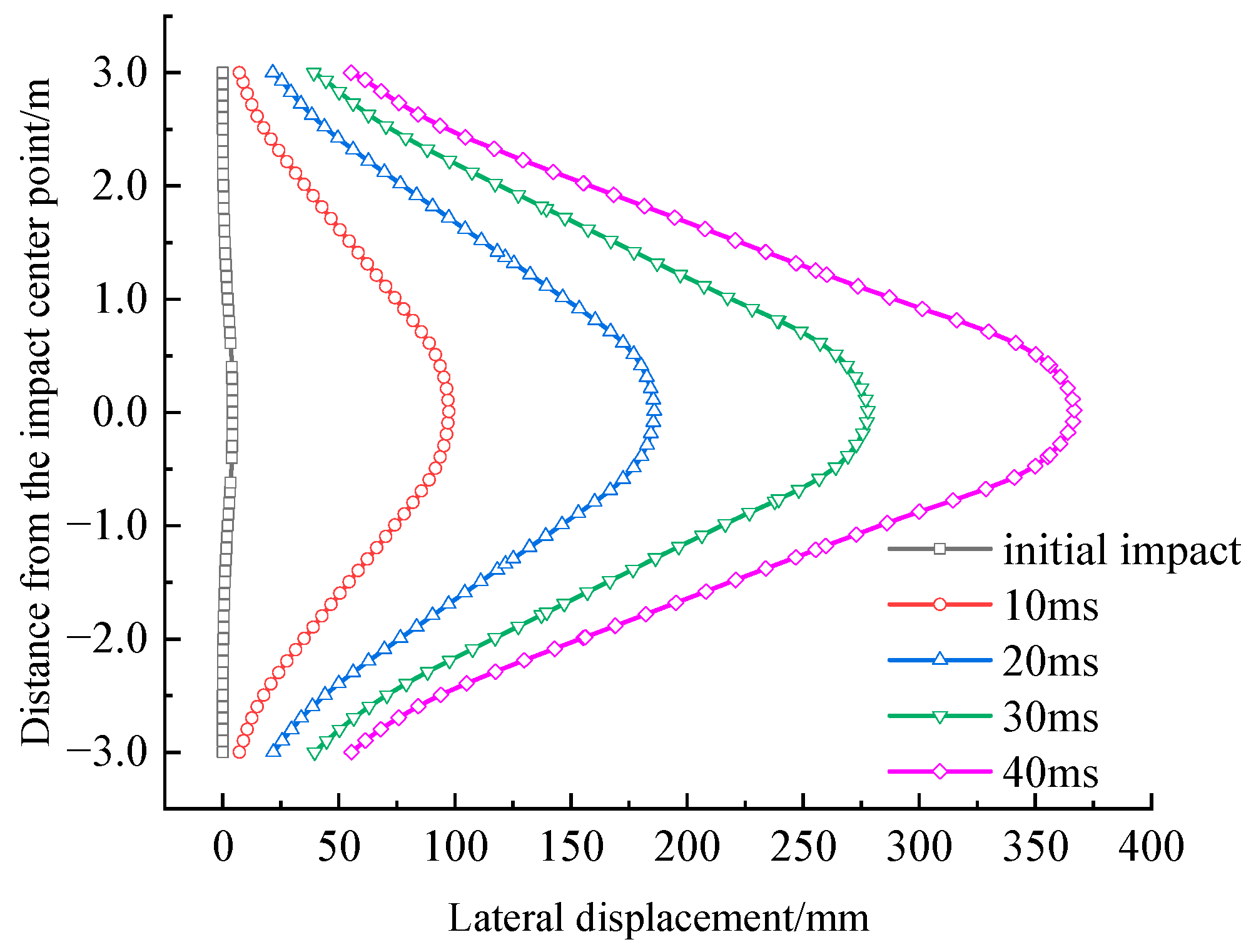
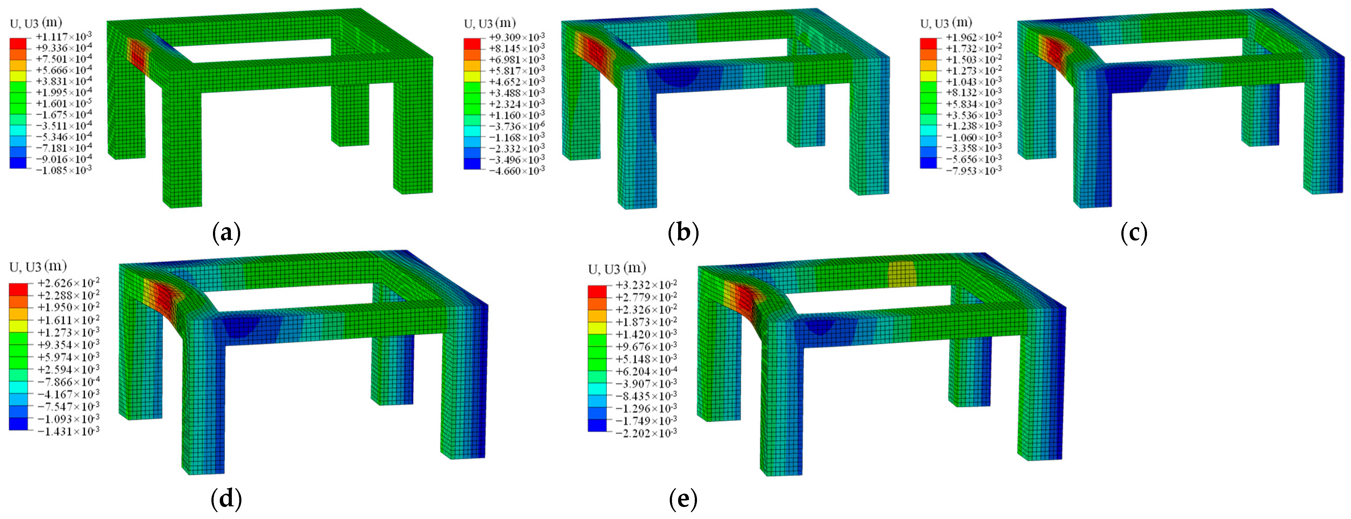
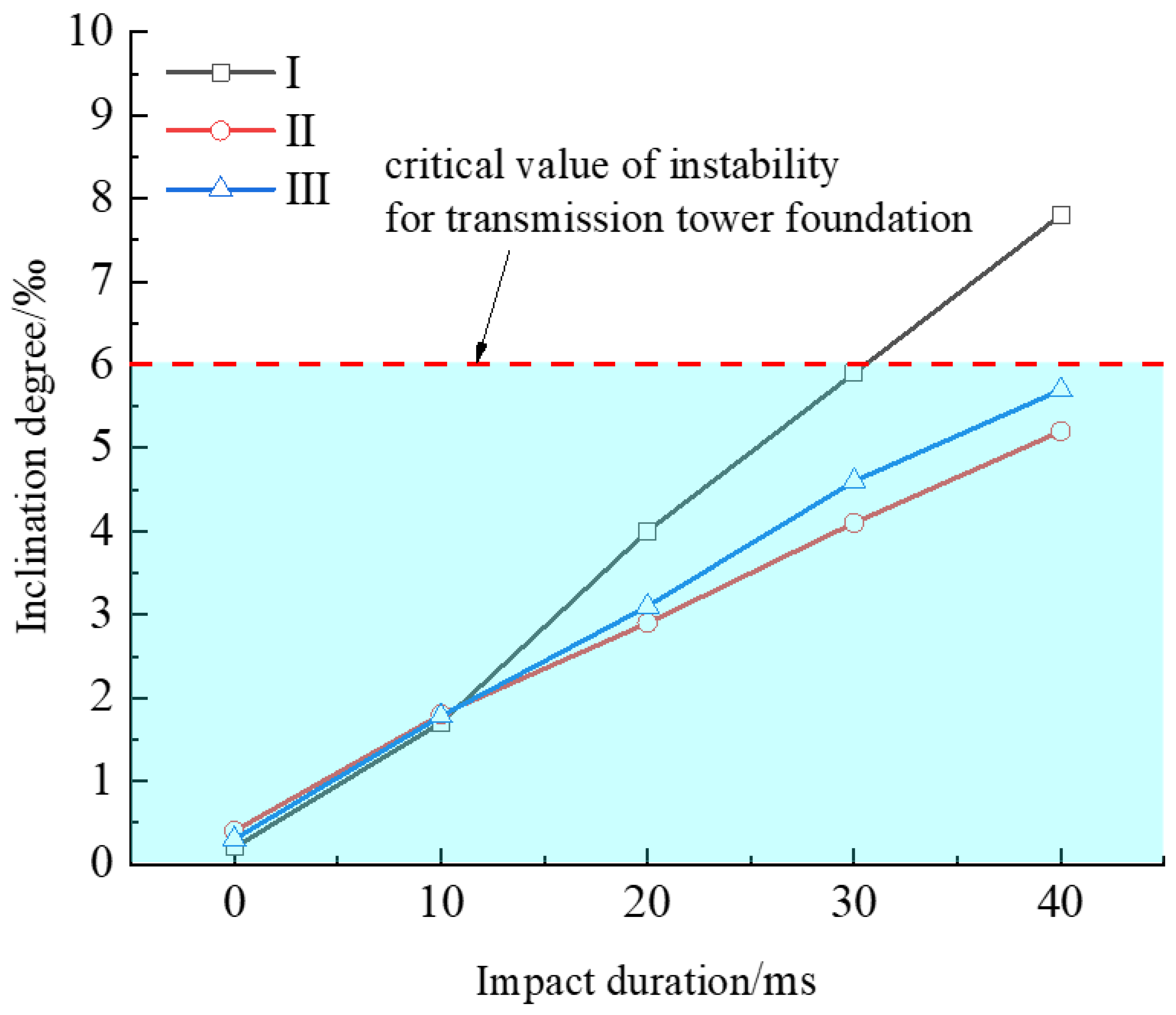
3.2. Different Impact Durations

Agricultural equipment and agricultural vehicles often stop when impacting a transmission tower foundation in practical engineering; that is, the impact duration is an instant. In some cases, agricultural equipment and agricultural vehicles still maintain a certain speed after impacting a transmission tower foundation, causing sustained damage to the transmission tower foundation. Therefore, it is necessary to study the deformation responses of a transmission tower foundation under different impact durations. Figure 4 illustrates the lateral displacement contours of the transmission tower foundation under different impact durations of the type I impactor.
As can be seen from Figure 4, a 4.4 mm lateral displacement occurred at the central point of the transmission tower foundation at the initial impact time. With the increase of the impact duration, the lateral displacement value increased continuously, and the area where the lateral displacement occurred gradually expanded. When the impact duration is taken as 10 ms, 20 ms, 30 ms, and 40 ms, the lateral displacement values of the impact center are 96.8 mm, 186.2 mm, 278.8 mm, and 368.8 mm, respectively. The lateral displacement values of individual points along the longitudinal center line of the connected beam under the impact effect were extracted (as shown in Figure 5). It can be found that the lateral displacement value increases with a smaller distance from the impact center point, and the lateral displacement values exhibit a parabolic shape along the longitudinal center line of the connected beam. In addition, it can be seen that with the increase of the impact duration, the lateral displacement curves of individual points along the longitudinal center line of the impacted connected beam move to the right continuously, and the bending degree of the impacted connected beam increases with the increase of the impact duration.
Figure 6 shows the vertical displacement contours of the transmission tower foundation under different impact durations with the type I impactor. It can be observed that with increasing impact duration, the left side of the transmission tower foundation will uplift to a certain extent, while the right side will sink to a certain extent, indicating that the transmission tower foundation has an obvious tendency to overturn in the rightward direction. Overturning failure is a common mode of instability failure in transmission tower foundations. The inclination degree index is defined as the ratio of the vertical maximum displacement difference between the near and far ends of the transmission tower foundation to the length of the transmission tower foundation. According to the maximum inclination degree rate of 6‰ stipulated in the Technical Code for Design of Overhead Transmission Line Foundation (DL/T519-2014) [25], the inclination degrees of the transmission tower foundation under different impact durations with the type I impactor are calculated. When the impact duration is taken as initial impact time plus 10, 20, 30, and 40 ms, the inclination degrees of the transmission tower foundation are 0.2‰, 1.7‰, 4.0‰, 5.9‰, and 7.8‰, respectively, indicating that the continuous impact effect will have a serious influence on the inclination degree of the transmission tower foundation. It is also found that when the impact duration exceeds 30 ms, the inclination degree of the transmission tower foundation surpasses the prescribed limit value, which indicates that the transmission tower foundation will sustain an obvious overturning failure under the continuous impact of the type I impactor.

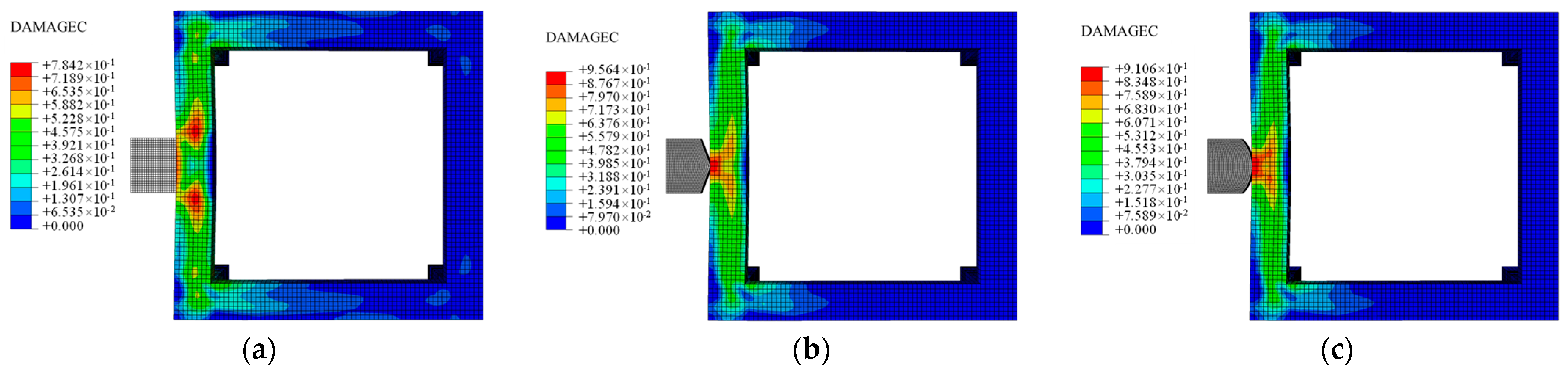
3.3. Different Shapes of Impactor

In practical engineering, there are various shapes and specifications of agricultural equipment and agricultural vehicles, resulting in a variety of different shapes of impact surfaces. In this study, these are simplified into a square impact surface, triangular impact surface, and semi-circular impact surface, corresponding to the type I, type II, and type III impactors, respectively. Figure 7 shows the pressure damage contours of the type I, type II, and type III impact objects on the transmission tower foundation at an impact speed of 30 km/h and an impact time of 5 ms.
It can be seen from Figure 7 that the damage position distributions and damage degrees of the transmission tower foundation are different under the impact effects of differently shaped impactors. The damage degree of the type I impactor is small in the front position, and there are two obvious damage areas at the corner position of the type I impactor. The obvious damage areas of the transmission tower foundations using the type II and type III impactors appear at the front positions of the impactors; that is, the obvious damage areas are mainly concentrated at the end positions of the impactors. It can also be seen from Figure 7 that under the impact effects of the type I, type II, and type III impactors, the compression damage values of the transmission tower foundation are 0.784, 0.956, and 0.911, respectively, which indicates that at the same impact time, the sharper the impactor is—that is, the smaller the impact contact area—the greater the compression damage value of the transmission tower foundation. With the continuation of the impact, the compression damage value of the transmission tower foundation under the Impact of the type II impactor reaches 0.99 first, which indicates that the sharper the impact object, the more likely the transmission tower foundation is to experience structural failure at an earlier stage.
In order to further compare the inclination degrees of the transmission tower foundation under the impact effects of the differently shaped impactors, the inclination degrees of the transmission tower foundation under different impact durations of the type I, II, and III impactors are shown in Figure 8. It can be seen that at the initial impact time, the inclination degrees of the transmission tower foundation for the different shapes are, from largest to smallest: type II, type III, and type I. This indicates that the smaller the impact contact area, the more susceptible the transmission tower foundation is to deformation under the impact effect. The inclination degree of the transmission tower foundation increases with increasing impact duration, and the variation law approximately follows a linear relationship. With the continuation of the impact, the inclination degree of the transmission tower foundation with the type I impactor exceeds the prescribed critical value of instability. Although the inclination degrees of the transmission tower foundation with the type II and type III impactors do not reach the prescribed critical values of instability, the small impact contact area causes the phenomenon of stress concentration, and the affected beam will take the lead in a structural failure during the impact process. The above results show that different impact contact areas will lead to different damage forms of the transmission tower foundation. When the impact contact area is small, structural failure is more likely to occur, while when the impact contact area is large, the transmission tower foundation is prone to overturning failure.

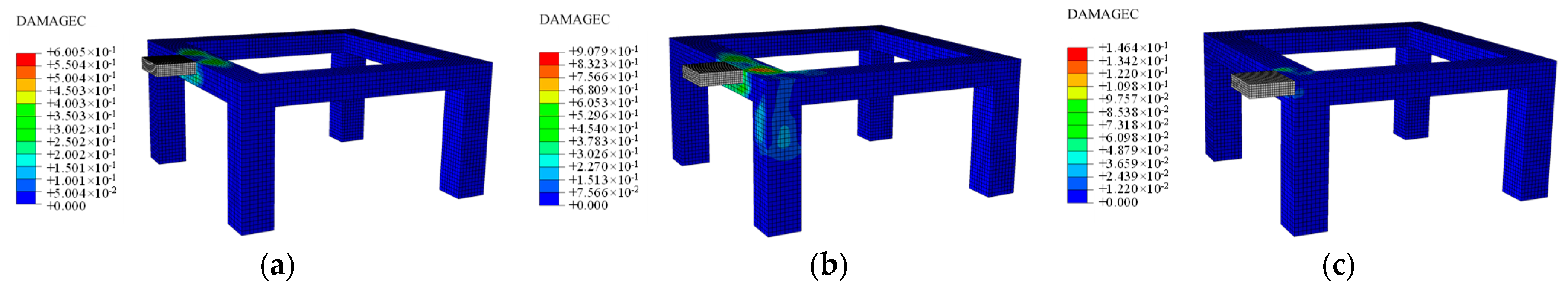
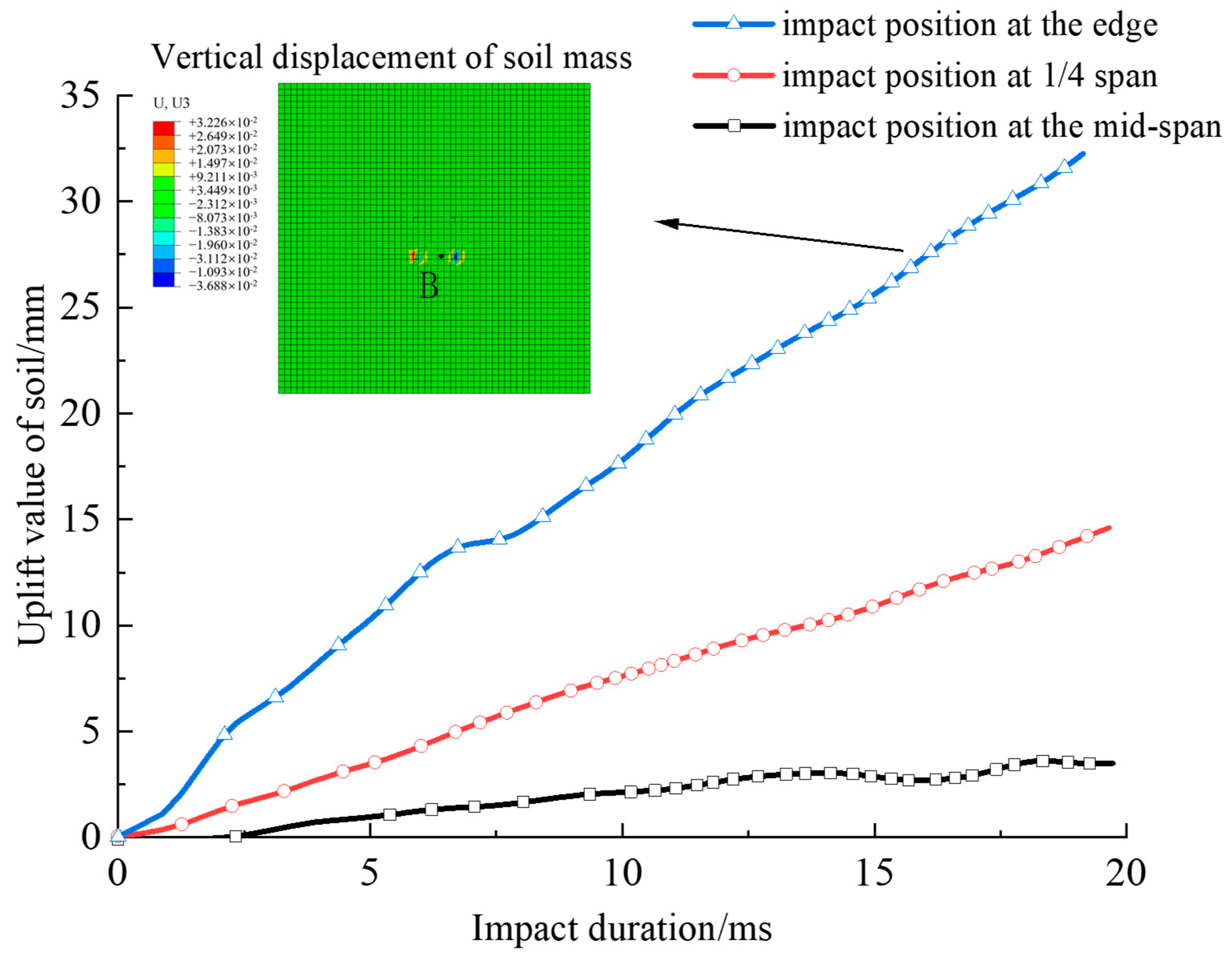
3.4. Different Impact Positions

When the position of the impact is different, the damage to the transmission tower foundation is also different. The center points of impacts are selected as the mid-span, quarter-span, and edge positions of the connecting beams of the transmission tower foundation. Figure 9 shows the compression damage contours of the transmission tower foundation when the type I impactor impacts different positions at the initial impact time.
As can be seen from Figure 9, there are significant differences in the damage to the transmission tower foundation when it is impacted at different locations at the initial impact time, and the maximum damage value is 0.60 when the impact position is the mid-span point; the maximum damage value is 0.91 when it is impacted at the quarter-span position; the maximum damage value is 0.15 when it is impacted at the edge position. A comparison reveals that when impacted at the edge position, the damage area of the transmission tower foundation is the smallest; that is because the impact load is shared by the connecting beam and the column foundation, and the impact load can be transmitted to the adjacent connecting beam. However, when impacted at the quarter-span position, the damage value and damage area of the transmission tower foundation are the largest, and certain damage areas also appear at the column position, among which the edge of the connecting beam connected to the column foundation is the most seriously damaged. With the continuation of the impact, the damage value of this position first reaches 0.99, indicating that this position is the weakest position of the transmission tower foundation and should be paid special attention in engineering design and protection.
During the impact process, the deformation and failure of the soil mass are observed at the same time. Because the deformation and failure of the soil mass can easily lead to rainwater infiltration and decrease the bearing capacity of the foundation, the deformation and failure of the soil mass are related to the stability of the foundation and can further affect the long-term stability of the transmission tower foundation. The variation curves of the uplift values of unit node B at the left front corner of the transmission tower foundation during the impact process were extracted, as shown in Figure 10. It can be observed that the uplift values of unit node B increase with continuous impacting, and the increase rates of the uplift values of unit node B are different when different positions are impacted. At the same impact time, the uplift value of unit node B is the largest when the impact occurs at the edge position; the uplift value of unit node B at the quarter-span position is the second largest; the uplift value of unit node B is the smallest when the impact occurs at the mid-span position, and the uplift value of unit node B when the impact occurs at the edge position is significantly greater than the uplift values of element node B in the other two impact cases. It can be seen that an impact at the edge position has a significant influence on the deformation of the surrounding soil of the transmission tower foundation.

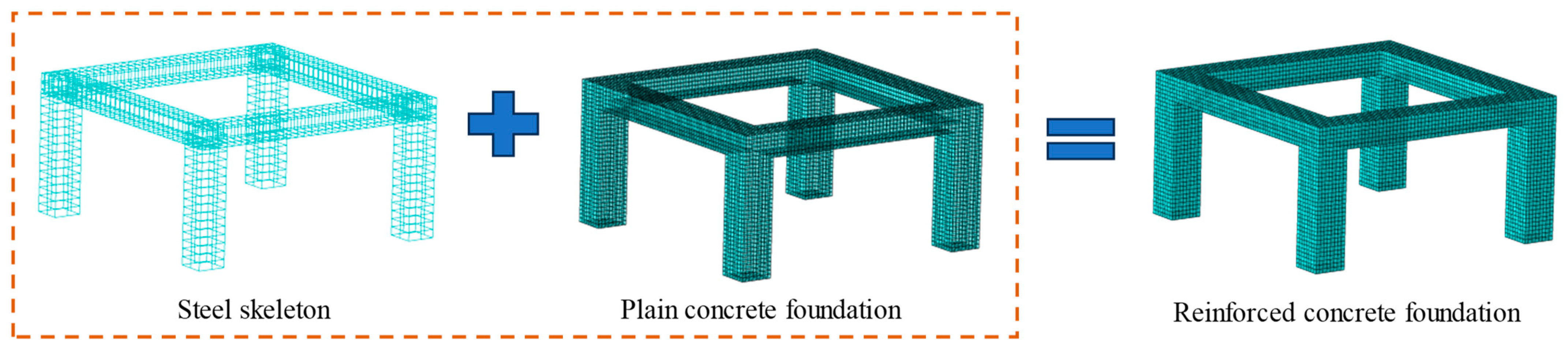
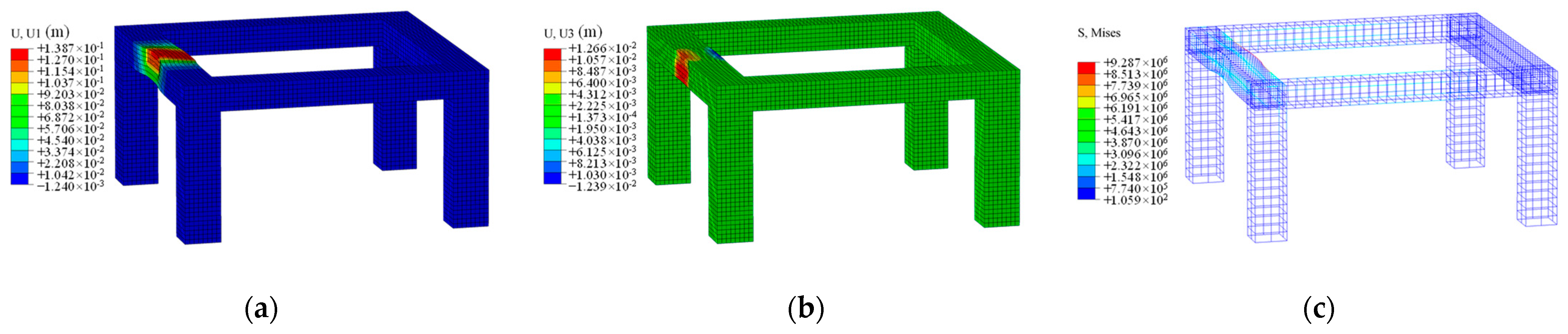
4. Comparative Analysis before and after Reinforcement Design

Longitudinal reinforcement bars and stirrups installed inside the transmission tower foundation can improve the bearing capacity and resistance to external loads of the transmission tower foundation and increase its overall stability, as shown in Figure 11. The density of the rebars in the model is 7800 kg/m3, the elastic modulus is 2.06 × 10⁵ MPa, and Poisson’s ratio is 0.3. The element was the three-dimensional truss element T3D2, and an ideal elastic–plastic model was used to simulate the stress and deformation characteristics of the rebars. Then, the rebar model was built into the transmission tower foundation model by embedding command [26,27].
Rebars of different types, that is, of different strengths, are used to reinforce the transmission tower foundation. Table 3 shows the deformation and damage values of the transmission tower foundation strengthened with rebars of different strengths when the impact velocity is 30 km/h and the impact duration is 20 ms. It can be seen that with the increase of the reinforcement strength, the maximum lateral displacement, maximum vertical displacement, inclination degree, and damage value of the transmission tower foundation decrease continuously. The reinforcement design using rebars of type HRB400 is taken as an example. Figure 12 shows the lateral displacement and vertical displacement contours of the reinforced transmission tower foundation when the impact velocity is 30 km/h and the impact duration is 20 ms. It can be seen that only the impacted beam of the reinforced transmission tower foundation deforms to a certain extent under the impact effect, while the impact has minimal effect on the other parts of the transmission tower foundation. In order to compare and analyze the deformation characteristics of the transmission tower foundation before and after reinforcement, Figure 12a,b are compared with Figure 4c and Figure 6c. It can be found that the maximum lateral displacement and vertical displacement of the transmission tower foundation before reinforcement are 186.2 mm and 19.6 mm, respectively, at the same impact time, while the maximum lateral displacement and vertical displacement of the transmission tower foundation after reinforcement are 138.7 mm and 12.7 mm, respectively, and the lateral displacement and vertical displacement of the transmission tower foundation after reinforcement have been reduced by 25.5% and 35.2%, respectively. This indicates that the lateral displacement and vertical displacement of the transmission tower foundation are significantly reduced, and the deformation area is significantly reduced after reinforcement. It is further calculated that the inclination degree of the transmission tower foundation after reinforcement is reduced by 47%, indicating that the reinforcement design can significantly improve the anti-deformation and anti-overturning ability of the transmission tower foundation. The main reason for the above phenomenon is that the steel skeleton participates in resisting the external impact load during the impact process. It can also be seen from the stress contours of the steel skeleton (Figure 12c) that the rebars built into the connecting beam generate a large resistance to stress and share the stress of the original concrete structure. In addition, during the impact, the steel skeleton dissipates a portion of the impact energy through plastic deformation, thereby reducing the overall deformation of the structure, which can better prevent the expansion of cracks and the occurrence of fractures.

5. Conclusions

In response to engineering accidents involving impacts on transmission tower foundations by agricultural equipment and agricultural vehicles in practice, a finite element numerical simulation method is used to study and analyze the variations in the damage degree, displacement, and inclination degree of a transmission tower foundation under different impact velocities, different impact durations, different shapes of impactor, and different impact positions. An exploratory study was conducted to investigate the influence of impacts on the stability of the transmission tower foundation. This study provides guidance for assessments of the stability and safety analyses of transmission tower foundations under impact loads in actual engineering applications. The main conclusions can be drawn as follows:
(1).
With increasing impact velocity, the damage value of the transmission tower foundation increases, and the damage area expands. The lateral displacement value of the transmission tower foundation increases with continuous impacting, the variation trend of the lateral displacement accords with a linear function distribution, and the lateral displacement of the transmission tower foundation increases with increasing impact velocity.
(2).
With the increase of the impact duration, the lateral displacement curves of individual points along the longitudinal center line of the impacted connected beam move to the right continuously, and the lateral displacement values show a parabolic shape along the longitudinal center line of the connected beam. The inclination degree of the transmission tower foundation increases with increasing impact duration, which indicates that continuous impacting will seriously affect the inclination degree of the transmission tower foundation and even cause overturning failure.
(3).
Different shapes of impactors have different damage position distributions and damage degrees for the transmission tower foundation under the impact effect. The sharper the impactor is—that is, the smaller impact contact area—the greater the compression damage value of the transmission tower foundation, and the more likely the transmission tower foundation is to experience structural failure at an earlier stage. The study also indicates that different impact contact areas lead to different modes of failure in transmission tower foundations. When the impact contact area is small, structural failure is more likely to occur, while when the impact contact area is large, a transmission tower foundation is prone to overturning failure.
(4).
The damage values and damage areas of the transmission tower foundation are different when the positions of the impactors are different. The damage value and damage area of the transmission tower foundation are the largest when the impact occurs at the quarter-span position, and the edge of the beam connected with the column foundation is the most seriously damaged, which means that this position is the weakest position of the transmission tower foundation. At the same impact time, the uplift value of unit node B is the largest when the impact occurs at the edge position, which means that an impact at the edge position has a significant influence on the deformation of the surrounding soil of the transmission tower foundation.
(5).
By using reinforcement bars of different strengths, the maximum lateral displacement, maximum vertical displacement, inclination degree, and damage values of the transmission tower foundation are continuously reduced. During the impact process, the steel skeleton participates in resisting the external impact load and shares the stress of the original concrete structure. Additionally, the steel skeleton dissipates a portion of the impact energy through plastic deformation. The reinforcement design significantly improves the deformation resistance and overturning resistance of the transmission tower foundation.

Author Contributions

L.S.: writing, methodology, conceptualization, data curation, and validation; S.C.: reviewing and funding acquisition; L.C.: supervision and writing; X.L.: data analysis and reviewing; J.L.: methodology and data analysis. All authors have read and agreed to the published version of the manuscript.

Funding

This research was funded by the National Natural Science Foundation of China (Grant No. 41902277 and 42172302) and Fundamental Research Funds for the Central Universities, CHD (Grant No. 300102282201), for which the authors are very thankful.

Institutional Review Board Statement

The study did not require ethical approval, and can exclude this statement.

Informed Consent Statement

The study did not involve humans, and can exclude this statement.

Data Availability Statement

The data used to support the findings of this study are included in the article.

Conflicts of Interest

The authors declare no conflict of interest.

References

  1. Liang, H.B.; Xie, Q.; Bu, X.H.; Cao, Y.X. Shaking table test on 1000 kV UHV transmission tower-line coupling system. Structures 2020, 27, 650–663. [Google Scholar] [CrossRef]
  2. Tian, L.; Pan, H.Y.; Ma, R.S. Probabilistic seismic demand model and fragility analysis of transmission tower subjected to near-field ground motions. J. Constr. Steel Res. 2019, 156, 266–275. [Google Scholar] [CrossRef]
  3. Fu, Z.Y.; Tian, L.; Liu, J.C. Seismic response and collapse analysis of a transmission tower-line system considering uncertainty factors. J. Constr. Steel Res. 2022, 189, 107094. [Google Scholar] [CrossRef]
  4. Park, H.; Choi, B.H.; Kim, J.J.; Lee, T.H. Seismic performance evaluation of high voltage transmission towers in South Korea. KSCE J. Civ. Eng. 2015, 20, 2499–2505. [Google Scholar] [CrossRef]
  5. Albayrak, U.; Morshid, L. Evaluation of seismic performance of steel lattice transmission towers. Civ. Eng. J. 2020, 6, 2024–2044. [Google Scholar] [CrossRef]
  6. Nazemi, M.; Dehghanian, P. Seismic-resilient bulk power grids: Hazard characterization, modeling, and mitigation. IEEE Trans. Eng. Manag. 2020, 67, 614–630. [Google Scholar] [CrossRef]
  7. Pan, H.Y.; Tian, L.; Fu, X.; Li, H.N. Sensitivities of the seismic response and fragility estimate of a transmission tower to structural and ground motion uncertainties. J. Constr. Steel Res. 2020, 167, 105941. [Google Scholar] [CrossRef]
  8. Li, J.K.; Gao, F.; Wang, L.H.; Ren, Y.N.; Liu, C.C.; Yang, A.Q.; Yan, Z.; Tao, J.; Li, C.B. Collapse mechanism of transmission tower subjected to strong wind load and dynamic response of Tower-Line system. Energies 2022, 15, 3925. [Google Scholar] [CrossRef]
  9. Ma, L.Y.; Khazaali, M.; Bocchini, P. Component-based fragility analysis of transmission towers subjected to hurricane wind load. Eng. Struct. 2021, 242, 112586. [Google Scholar] [CrossRef]
  10. Bernuzzi, C.; Crespi, P.; Montuori, R.; Nastri, E.; Simoncelli, M.; Stochino, F.; Zucca, M. Resonance of steel wind turbines: Problems and solutions. Structures 2021, 32, 65–75. [Google Scholar] [CrossRef]
  11. Mozakka, I.; Zeynalian, M.; Hashemi, M. A feasibility study on construction methods of high voltage transmission towers’ foundations. Arch. Civ. Mech. Eng. 2021, 21, 41. [Google Scholar] [CrossRef]
  12. Liu, H.Y.; Du, M.R.; Zhang, B.Y.; Lin, Z.B.; Liu, C.W.; Wang, F. Study on the combined mining scheme for coal resources under high-voltage pylons and the reinforcement for pylons. Energies 2022, 15, 3978. [Google Scholar] [CrossRef]
  13. Yang, F.L.; Yang, J.B.; Han, J.K.; Zhang, Z.F. Study on the limited values of foundation deformation for a typical UHV transmission tower. IEEE Trans. Power Deliv. 2010, 25, 2752–2758. [Google Scholar] [CrossRef]
  14. Gao, X.Y.; Yi, R.; Zhang, L.Q.; Jiang, X.; Li, J.X. Failure analysis of transmission tower in full-scale tests. Buildings 2022, 12, 389. [Google Scholar] [CrossRef]
  15. Shu, Q.J.; Yuan, G.L.; Guo, G.L.; Zhang, Y.F. Limits to foundation displacement of an extra high voltage transmission tower in a mining subsidence area. Int. J. Min. Sci. Technol. 2012, 22, 13–18. [Google Scholar] [CrossRef]
  16. Zhou, Y.B.; Zhou, L.; Duan, Z.Q.; Ke, F.C.; Liu, H. Analysis of the influence of the distribution and development of soil caves on the stability of High-Voltage Transmission Tower foundations. Adv. Civ. Eng. 2022, 2022, 2856947. [Google Scholar] [CrossRef]
  17. Yao, A.J.; Lin, J.B.; Ren, B. The influence of small clear-distance tunnel construction on adjacent high-voltage transmission tower foundation. Adv. Civ. Eng. 2023, 2023, 2533212. [Google Scholar] [CrossRef]
  18. Wang, F.; Zhang, G.H.; Li, W.W.; Nie, H.W. Numerical investigation into the effects of controlled tunnel blast on dynamic responses of the transmission tower. Arch. Civ. Mech. Eng. 2023, 2023, 6021465. [Google Scholar] [CrossRef]
  19. Xin, W.S.; Liu, J.K.; Li, X.; Hu, T.F.; Kolos, A. Frost jacking characteristics of prefabricated cone cylindrical tower foundation in cold regions. Cold Reg. Sci. Technol. 2023, 211, 103847. [Google Scholar] [CrossRef]
  20. Yuan, H.P.; Zhao, P.; Wang, Y.X.; Zhou, H.L.; Luo, Y.H.; Guo, P.P. Mechanism of deformation compatibility and pile foundation optimum for Long-Span tower foundation in Flood-Plain deposit zone. Int. J. Civ. Eng. 2016, 15, 887–894. [Google Scholar] [CrossRef]
  21. Chi, Y.; Yu, M.; Huang, L.; Xu, L.H. Finite element modeling of steel-polypropylene hybrid fiber reinforced concrete using modified concrete damaged plasticity. Eng. Struct. 2017, 148, 23–35. [Google Scholar] [CrossRef]
  22. Van Nguyen, D.; Kim, D.; Nguyen, D. Nonlinear seismic soil-structure interaction analysis of nuclear reactor building considering the effect of earthquake frequency content. Structures 2020, 26, 901–914. [Google Scholar] [CrossRef]
  23. Xiang, S.; Zeng, L.; Liu, Y.H.; Mo, J.X.; Ma, L.L.; Zhang, J.C.; Chen, J. Experimental study on the dynamic behavior of T-shaped steel reinforced concrete columns under impact loading. Eng. Struct. 2020, 208, 110307. [Google Scholar] [CrossRef]
  24. Bian, M.H.; Peng, J.N.; Qin, S.L.; Zhang, X.S.; Li, J.H. A simplified analytical method for lateral dynamic responses of a transmission tower due to rockfall impact. Front. Mater. 2023, 10, 1229327. [Google Scholar] [CrossRef]
  25. DL/T5219-2014; Power Industry Standard of the People’s Republic of China, Technical Code for Design of Overhead Transmission Line Foundation. China Planning Press: Beijing, China, 2014.
  26. Lee, S.; Abolmaali, A.; Shin, K.; Lee, H. ABAQUS modeling for post-tensioned reinforced concrete beams. J. Build. Eng. 2020, 30, 101273. [Google Scholar] [CrossRef]
  27. Quan, D.Z.; Chai, S.B.; Wang, Y.L.; Fan, Z.S.; Bu, Y.H. 3-D numerical simulation of seismic response of the induced joint of a sub-way station. Buildings 2023, 13, 1244. [Google Scholar] [CrossRef]
Figure 1. Schematic diagram of the numerical model of the transmission tower foundation.
Buildings 13 03047 g001
Figure 2. Compression damage contours of the transmission tower foundation at initial impact time under different impact velocities: (a) v = 10 km/h; (b) v = 20 km/h; (c) v = 30 km/h.
Buildings 13 03047 g002
Figure 3. Lateral displacement time history curves of unit node A under different impact velocities.
Buildings 13 03047 g003
Figure 4. Contours of the lateral displacement of the transmission tower foundation under different impact durations: (a) initial impact time; (b) 10 ms; (c) 20 ms; (d) 30 ms; (e) 40 ms.
Buildings 13 03047 g004
Figure 5. Lateral displacement values of individual points along the longitudinal center line of the impact beam.
Buildings 13 03047 g005
Figure 6. Vertical displacement contours of the transmission tower foundation under different impact durations: (a) initial impact time; (b) 10 ms; (c) 20 ms; (d) 30 ms; (e) 40 ms.
Buildings 13 03047 g006
Figure 7. Contours of the compression damages of the transmission tower foundation under different impactor shapes: (a) type I; (b) type II; (c) type III.
Buildings 13 03047 g007
Figure 8. Inclination degrees of the transmission tower foundation under different impactor shapes.
Buildings 13 03047 g008
Figure 9. Compression damage contours of the type I impactor at different locations at the initial impact time: (a) impact mid-span position; (b) impact quarter-span position; (c) impact edge position.
Buildings 13 03047 g009
Figure 10. Variation curves of the uplift value of unit node B at the left front corner of the transmission tower foundation.
Buildings 13 03047 g010
Figure 11. Schematic diagram of the numerical model of the reinforced transmission tower foundation.
Buildings 13 03047 g011
Figure 12. Contours of the lateral displacement, vertical displacement, and rebar cage stress of reinforced transmission tower foundation: (a) lateral displacement; (b) vertical displacement; (c) steel skeleton stress contour.
Buildings 13 03047 g012
Table 1. Material parameters of individual components of the numerical model.
ComponentDensity (kg/m3)Elastic Modulus (MPa)Poisson’s RatioFriction Angle (°)Cohesive Force (kPa)
Clay1700280.352020
Limestone2100560.322517
Transmission tower structure7850206,0000.30--
Transmission tower foundation250030,0000.15--
Impactor7850206,0000.30--
Table 2. Parameters of the concrete damage plastic model.
ParameterDilation AngleEccentricityfb0/fc0Invariant Stress Ratio KViscosity
Parameter
Value300.11.160.66670.001
Table 3. Deformation and damage values of the transmission tower foundation after reinforcement with rebars of different strengths.
Rebar TypeMaximum Lateral Displacement (mm)Maximum Vertical Displacement (mm)Inclination
Degree (‰)
Damage Value
HRB335152.315.82.60.836
HRB400138.712.72.10.818
HRB500127.911.21.90.792
Disclaimer/Publisher’s Note: The statements, opinions and data contained in all publications are solely those of the individual author(s) and contributor(s) and not of MDPI and/or the editor(s). MDPI and/or the editor(s) disclaim responsibility for any injury to people or property resulting from any ideas, methods, instructions or products referred to in the content.

