Article

Assessment of Existing Masonry Resistance Using Partial Factors Approaches and Field Measurements

Faculty of Civil Engineering, University of Zagreb, 10000 Zagreb, Croatia
*
Author to whom correspondence should be addressed.
Buildings 2023, 13(11), 2790; https://doi.org/10.3390/buildings13112790
Submission received: 16 October 2023 / Revised: 31 October 2023 / Accepted: 3 November 2023 / Published: 6 November 2023

Abstract

:
The vast majority of existing structures in Croatia, as well as in other European countries, are made of unreinforced masonry. The seemingly ideal building material presents a great challenge for engineers in earthquake-prone zones. Given that structural failure can have significant consequences in terms of loss of human lives as well as financial losses, a comprehensive structural reliability assessment is needed. Old existing masonry structures often do not have design documentation, and even when they do, the initial mechanical properties have almost certainly degraded over time. That is why in situ testing is of great importance, but masonry is also characterized by a large scattering of results. After recent severe earthquakes in Croatia, more than ever, there is a need for a more reliable assessment of existing masonry structures. This paper presents reliability approaches for resistance evaluation of existing masonry in a real case study where basic failure modes of the masonry were observed. First, the data recommended in standards were used, followed by the updated data obtained from the flat-jack test. Finally, the design value method (DVM) and the adjusted partial factor method (APFM) were used. These methods align with Eurocode standards for new structures but are also adaptable for the assessment of existing structures. Differences in the results between the existing and the new version of the standard were observed, as well as an increase in the obtained resistances with an increase in the complexity of the methods used. Also, the influence of in situ testing proved to be an important factor in the analysis.

1. Introduction

Throughout history, masonry has been used extensively. Over time, due to the gradual development of modern materials, the use of masonry slowly decreased. Nevertheless, masonry structures are still widely used worldwide due to their good thermal and acoustic properties, good fire resistance as well as fast and simple construction [1,2]. The vast majority of existing structures in Croatia, as well as in other European countries, are made of unreinforced masonry (URM). This seemingly very good building material presents a great challenge for engineers when combined with significant seismic risk [3,4,5,6], as can be found in Zagreb and other regions in Croatia [7]. Existing URM structures are characterized by significant weight, flexible timber diaphragms and high rigidity. In addition, they have low ductility as well as scarce dissipation of seismic energy [8]. Also, out-of-plane failure, formation of local mechanisms and disaggregation are frequent occurrences in existing URM structures built before seismic regulations [9,10]. Today, after recent devastating earthquakes in 2020, ML = 5.5 in Zagreb and ML = 6.3 in Petrinja, there is, more than ever, a need for a more reliable assessment of existing masonry structures. Such an assessment will provide important information essential for further decision-making and have a positive long-term effect on the safety and economic aspects of existing building stock management. Hence, different reliability approaches for resistance assessment of existing masonry are presented through a real case study. Such case studies are generally rapidly evaluated immediately after an earthquake to determine usability according to the EMS-98 scale [11]. Afterward, more detailed inspection and in situ tests are conducted to determine the current state of the geometric and mechanical properties as well as the detailing of the structure. The results obtained from the investigative work are essential since they serve as input data for further analysis [12]. Furthermore, input data and knowledge essential for post-earthquake assessment can be updated through novel methods such as value of information (VoI) analysis. Also, the use of machine-learning techniques can be useful in the seismic assessment of existing structures [13]. Various methods are used for investigative work. Some are non-destructive, such as ultrasound, sonic pulse velocity, operational modal analysis, photogrammetry and close-range remote sensing using unmanned aerial vehicles. Common semi-destructive methods are flat-jacks, shear tests, compression tests and core sampling. Some of the mentioned methods are explained in more detail in the following papers [14,15]. The typical in-plane failure modes used in this research as well as out-of-plane failure modes of URM walls, are explained in more detail in [16,17]. During earthquakes, structures made of different materials and built in various periods are damaged. Therefore, they should be approached properly [18,19]. For example, vernacular architecture combines a cultural tradition and adaptation, resulting in resilient and sustainable systems [20,21]. Hence, it should be strengthened accordingly. On the other hand, more modern structures should be strengthened with a modern solution, but again, their cultural value should be preserved. Therefore, a less invasive and reversible strengthening technique like textile-reinforced mortar (TRM) [8] can be used.
When it comes to the reliability assessment of new versus existing structures, three major differences arise [22]. First, due to age, the remaining service life and, thus, the reference period of the existing structure is noticeably shorter than the design service life of 50 years assumed for new structures. This leads to reduced load values. Second, the geometric and mechanical properties of the structure change and/or degrade over time. Therefore, a detailed survey of the existing structure is required, while, on the other hand, the new structure has predefined geometric and material properties with known reliability. Third, if an increase in the reliability level is required, integrating strengthening procedures into the new structure during the design phase is much easier and more cost-effective than retrofitting the existing structure.
This manuscript aims to determine the resistance level of an existing URM wall through several approaches. Four basic failure modes of the masonry are observed. These are bending, shear sliding, flat and stepped diagonal failure [23]. Initially, data that are a combination of recommendations from standards and assumptions are used. Then, the data obtained by flat-jack testing are used to update previously used data. Moreover, the adjusted partial factor method (APFM) and the design value method (DVM) [24,25] are conducted to obtain adjusted partial safety factors for the safety evaluation of the analyzed URM wall.
In the first part of the paper, a brief overview of various methods used in the field of structural reliability assessment is provided. The second part presents the application of the mentioned methods in a real case study of a URM building. Finally, the discussion and conclusions follow.

2. Input Data and Methods

Given that structural failure can have significant consequences in terms of loss of human lives as well as financial losses, a comprehensive structural reliability assessment is needed. Some methods make it relatively easy to solve everyday problems with sufficient precision. In contrast, some methods are more suitable for more complicated problems requiring high precision levels when performing reliability verification. Examples of structural reliability methods used in structural engineering are ref. [26] for timber structures, ref. [27,28] for steel structures, ref. [29,30,31,32] for masonry structures and ref. [33,34,35] for concrete structures. Several factors influence the reliability of structures designed according to Eurocodes. In the case of input data, mechanical properties are one of these since they are not constant but vary randomly [36]. The following sub-section provides a brief overview of various methods used in the field of structural reliability assessment.

2.1. Structural Reliability Methods

Every structure is designed with a certain reliability to fulfill particular safety, serviceability and durability requirements during its service life. In general, structural reliability methods can be divided into three basic categories. The deterministic approach is based on experience and is simpler to apply. Due to its shortcomings, it is slowly falling out of use. It is replaced by a semi-probabilistic approach based on limit states. The idea is to prevent the failure of the element or the structure itself. The last and most advanced approach is probabilistic. It is similar to the previous approach and is slowly being applied more and more [37]. The full probabilistic analysis is the most detailed and sophisticated of all the mentioned analyses. Its advantage is that partial factors are not used to account for the variation in input parameters. Instead, distribution functions are used to represent the natural dispersion of the values of the input parameters in more detail. In this way, excessive design is avoided, leading to more economical and sustainable management of the existing building stock. The mentioned approaches and associated methods are shown in Table 1.
Currently, a semi-probabilistic or level I approach (level II is FORM and level III is a full probabilistic method) is implemented in Eurocode 0–Annex C [38], which is a transitional phase between the two approaches mentioned above.
For every structure, the ultimate limit states and the serviceability limit states must be met with an appropriate reliability level throughout the service life and in line with the purpose of the structure. Also, a reliable structure implies the existence of a reliability or safety margin that delimits a reliable and unreliable state in which the structure can be found [39]. The determination of the reliability margin, i.e., the assessment of the reliability of the structure, is obtained by comparing the effects of actions (E) and resistance (R) characterized by uncertainties that change/degrade over time. The basic semi-probabilistic verification format according to the Eurocode is shown by Equation (1):
R k γ R E k γ E
where Ek and Rk are the main groups of characteristic value of basic variables, while γR and γE are partial factors for resistance and loads, respectively [40]. Basic variables are all random values described by distribution functions. For example, a Gaussian or lognormal distribution can be assumed for geometric and material properties [41].
When using reliability-based methods, the reliability index β and the probability of failure Pf tell us whether the structure is safe, β = Φ 1 ( P f ) . We can calculate the probability of failure Pf, which can be expressed with the limit state function g (or performance function) and the vector of base variables X. The limit state function g(X) = 0 divides the total space, described by X, into safe and unsafe areas. The mentioned failure probability Pf can be expressed as Pf = P(RE < 0) where R is the resistance function and E is the load function. The uncertainty and randomness of these events are fundamental principles in the structural reliability theory. These principles are the leading cause of the gradual change in structural reliability verification from a deterministic approach to a more complete probabilistic approach.

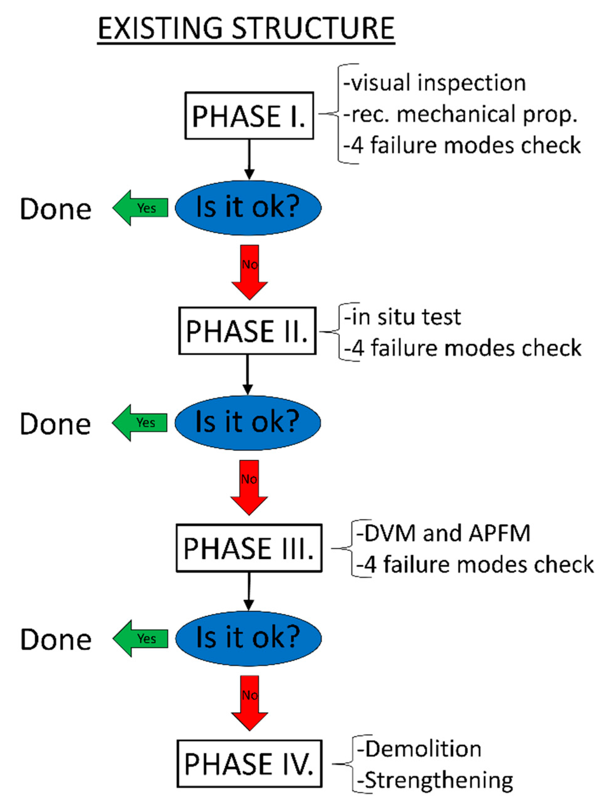
2.2. Procedures in the Assessment of Existing Masonry Structures and Target Reliability Levels

Assessing existing structures is necessary concerning load changes and degradation of mechanical properties associated with time. The assessment procedures themselves differ according to the scope of the work, its complexity and the methods used. According to the Structural Assessment, Monitoring and Control (SAMCO) network [37], six assessment levels exist. These range from an informal qualitative assessment based only on visual inspection (level 1) to a quantitative assessment which can be divided into a measurement-based and model-based assessment that ends with a full probabilistic assessment where the results of testing and monitoring with their statistical properties and probabilistic modeling of uncertainty are used (level 6) [37]. All levels are shown in more detail in Table 2.
Existing structures are a large part of the building stock, and thus, their management constitutes a significant part of the total investments in construction. Since using the same reliability procedures for existing and new structures is not economical, the target reliability levels should not be the same. The existing structures are also specific because the return to the original state regarding load-bearing capacity and/or safety is not often economically justified; therefore, a compromise can be agreed upon to reduce reliability by reducing the reliability index. A similar situation occurred in Zagreb after the earthquake, where a new law [43] allowed the restoration of damaged existing structures to lower levels of resilience than new structures must meet. Thus, seismic resistance levels of 50%, 75% and 100% of the required resistance of new structures are created. Considering the age and levels of damage to existing structures, the renovation formulated in this way enabled flexibility depending on the wishes of the owner, the level of damage and financial possibilities, and thus, greater efficiency. Indeed, the safety of human lives must be given priority over economic benefits. Consequently, a reduced value of the reliability index causes a decrease in the value of the partial safety factors. Appropriately, the levels of reductions should be different for different consequence classes.
Acceptable levels of safety, serviceability and durability requirements or targeted reliability levels are quite important, especially for the assessment of existing structures. Relevant guidelines and standards such as fib Bulletin 80 [25], EN 1990 [38], ISO 13822 [44], ISO 2394 [45], CEN/TS 17440:2020 [46], SAMCO [37] and JCCS [47] have a lot to offer on the subject. According to ISO 13822 [44] and ISO 2394 [45] the remaining service life, human safety and economic aspects of the existing structures have a significant impact on obtaining the target reliability level. The values are given for a service life of 50 years, and it is questionable what to do with the shorter remaining service life. As for the current EN 1990 [38], it provides target reliability values that are more suitable for new structures. In addition, the new proposal of EN 1990-2 [48] allows lower target reliability values for existing and rehabilitated structures because the relative cost of increasing the reliability of an existing structure is higher than that of a new structure. Table 3 shows the target reliability values proposed in SAMCO [37], which are based on the ISO 13822 standard [44]. This provides minimum reliability index values for various limit states with a remaining life of 50 years.
Table 4 shows the minimum reliability index values depending on the reliability class and the remaining service life proposed in EN 1990 [38]. The reference periods are 50 years, while the reliability classes have 3 categories. EN 1990 classifies all common structures, regardless of material and static system, in RC2 and the calculation procedure of such structures is based on the standardized method of partial factors. In practice, exceptional structures classified as RC3 are also possible. Although EN 1990 gives reliability index values for such structures, it does not propose corresponding partial factors, but generally, such structures require higher partial factors.

2.3. DVM and APFM

The design value method (DVM) and adjusted partial factor method (APFM) are given in fib 80 [25,38]. These methods align with Eurocode standards for new structures but are also adaptable for the reliability assessment of existing structures. In the case of the latter, only the target reliability levels and the remaining service life must be adjusted. In addition, the update procedure can also be used when the prior information about the basic variables of the existing structure is obtained indirectly. Overall, the DVM and APFM methods are more suitable for the assessment of existing structures than the standard verification methods used for new structures [24]. Similar case study analyses with the application of modified partial factors for reliability verifications were carried out in [33,41].

2.3.1. Design Value Method (DVM)

The design value approach for the partial factor method determines the partial factor in accordance with the distribution of the observed variable. The obtained partial factor considers the variability of the material, model uncertainty and geometric uncertainty. It can be determined by Equation (2):
γ M = γ R d γ m = γ R d 1 γ R d 2 γ m
where γM is the final partial factor for resistance, γm the partial factor accounting for material variability, γRd1 the partial factor accounting for model uncertainty and γRd2 the partial factor accounting for geometrical uncertainties [25]. Partial factors accounting for the variability of the material can be determined by Equation (3):
γ m = x k x d = μ x exp ( 1.645 V x ) μ x exp ( α R β V x ) = e ( 1.645 V x ) e ( 0.8 β V x )
where Xk is the characteristic value for material properties, Xd the design value for material properties, µx the mean value of variable X, β the reliability index and Vx the coefficient of variation of variable X. Partial factor accounting for model uncertainty can be determined by Equation (4):
γ R d 1 = μ θ R θ R d = 1 1 α R β V θ R = 1 1 0.4 0.8 β V θ R
where µϴR is the mean value of variable ϴ, ϴRd the random variable, αR the sensitivity factor for resistance (0.32 according to [49]) and VϴR the coefficient of variation of variable ϴ.
Partial factor accounting for geometrical uncertainties can be assumed to be γRd2 = 1.0 if measurements of a structure indicate insignificant variability of geometrical properties.

2.3.2. Adjusted Partial Factor Method (APFM)

The product of the partial factor for the new structure and the adjustment factor is used in the adjusted partial factor approach. It can be determined by Equation (5):
γ x = w y γ x , n e w
where γx is the partial factor for resistance, wy the adjustment factor and γx,new the partial factor for resistance for new structures.
The equation for the adjustment factor calculation is different depending on whether the representative value of the material property is characteristic or mean and whether it is a normally distributed variable or a lognormally distributed variable. Here, the adjustment factor for the mean value of material properties and a lognormal distribution can be determined by Equation (6):
w y = γ Rd ( β ) γ Rd ( β ) exp ( α R β V x ( β β V x V x 1 ) )
where γRd is the partial factor accounting for model and geometrical uncertainty (same as in the DVM method), β′ the reliability index for new structures, β″ the reliability index for existing structures, αR the sensitivity factor for resistance and Vx the coefficient of variation of variable X.

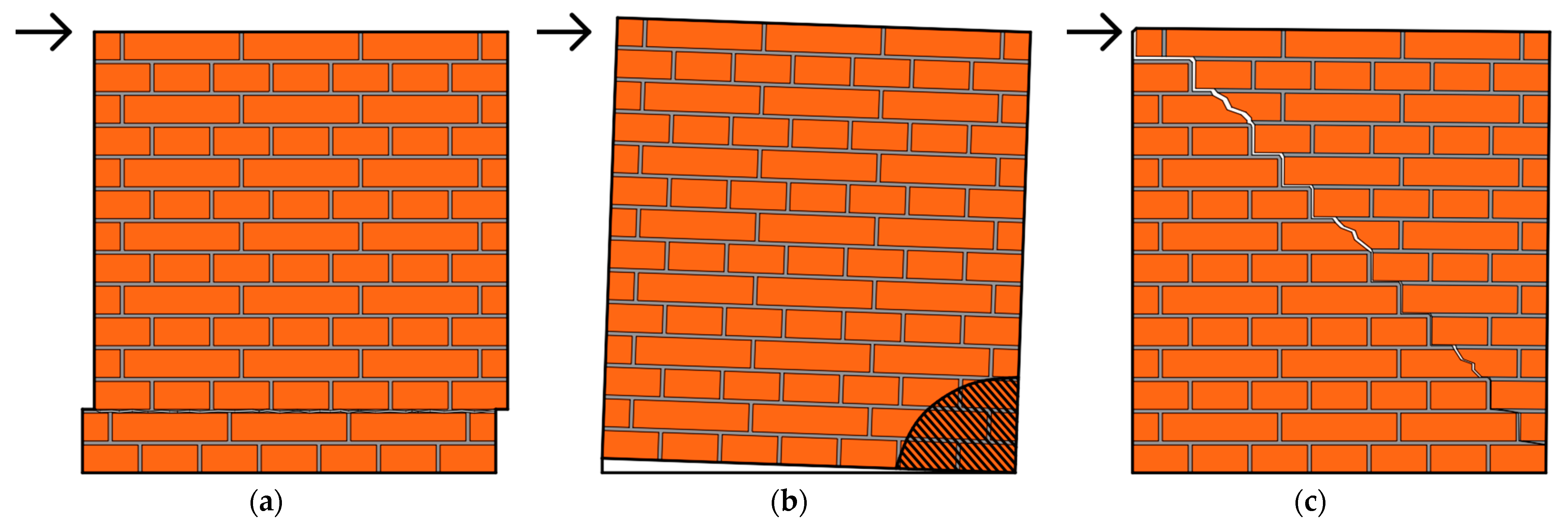
2.4. Failure Modes of URM According to the Current and New Proposal of EN 1998-3

There are three basic failure modes for masonry (Figure 1). These are shear sliding (Equations (7)–(9)), bending (Equations (10)–(14)) and diagonal failure (which further can be divided into flat (Equations (15)–(16)) and stepped diagonal failure (Equation (17)).
All equations used for the resistance calculation for the mentioned failure modes for both the existing and the new proposal of standard EN 1998-3 [50,51] are listed in Table 5. The dominant failure mode is the one that has the least resistance. It depends on the material quality, the state of vertical stress in the masonry and the typology of the masonry. A detailed resistance calculation for mentioned failure modes can be found in [8].

3. Case Study

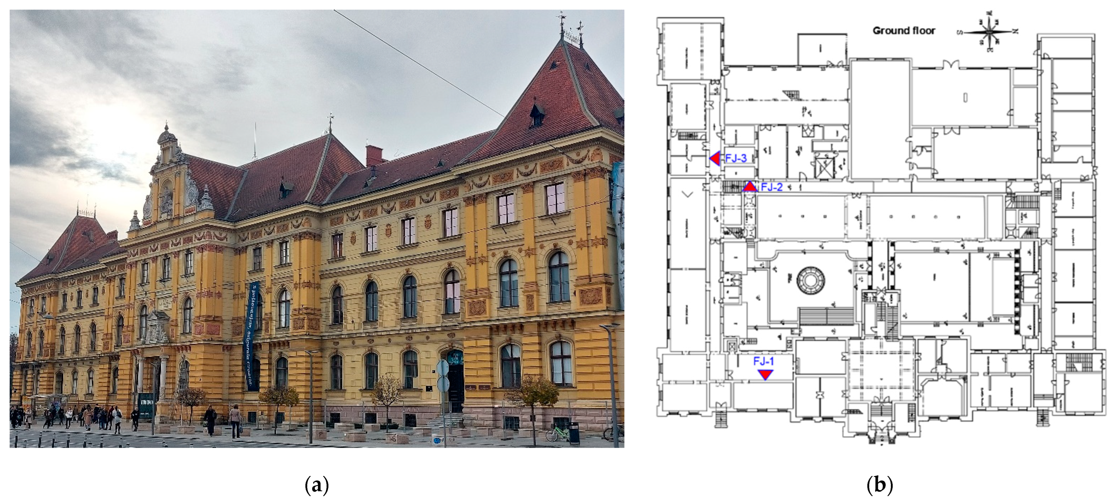
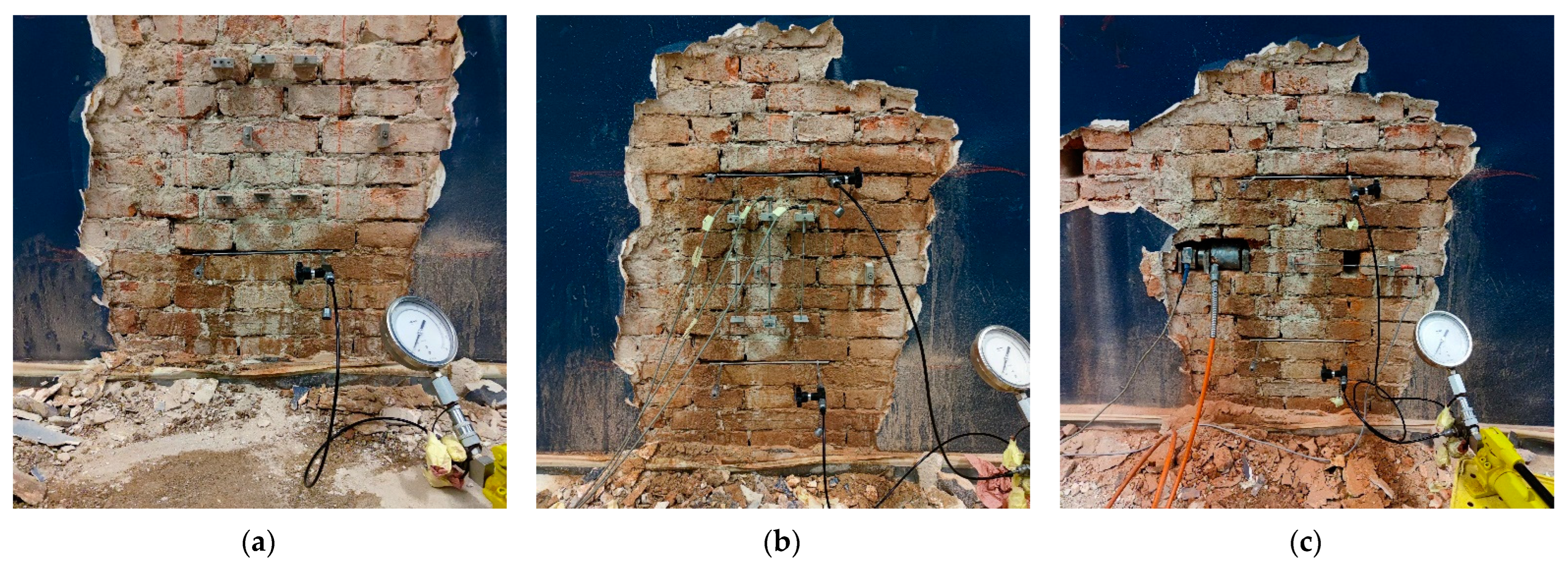
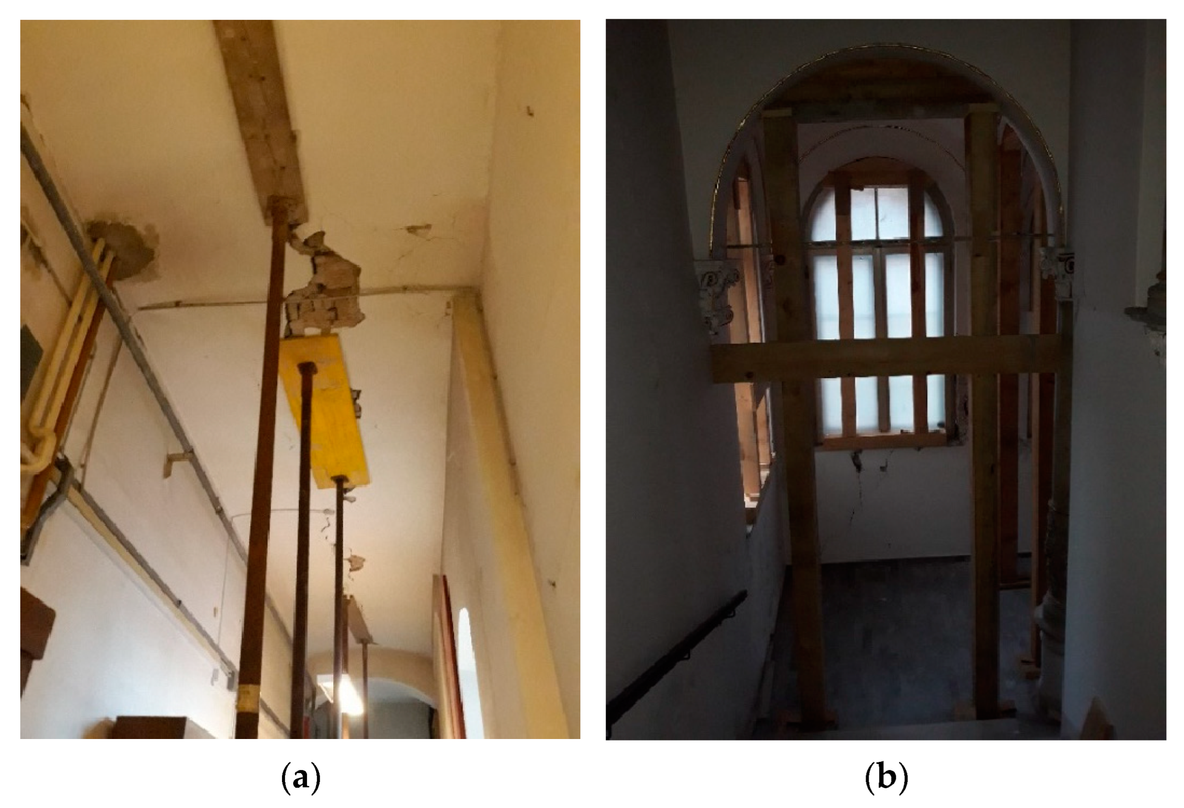
3.1. Case Study Information

The selected case study building is located in one of the most impressive squares in the historical center of Zagreb. The building has a cultural and artistic purpose, as it houses a museum of arts and crafts. Usually the host of various highly attended cultural events, the building is currently closed due to damage caused by recent earthquakes. The building was built in 1888 in the spirit of the German Renaissance and has a basement, ground floor, two floors and attic. The main load-bearing structure is URM (50–60 cm thick walls) with low-stiffness floor structures (masonry vaults in the basement and timber beams on other floors). The roof structure is also made of timber. The east facade and ground floor plan of the building are shown in Figure 2a,b.
Given that the mechanical properties of existing masonry structures can vary greatly, it is very useful to determine the actual values of these properties through in situ testing [52]. As part of the investigative work, flat-jack tests were performed on three original load-bearing walls from the same construction period that have a similar thickness. The locations of the tests are marked with red triangles in Figure 2b. All phases of the test itself are shown in Figure 3.
Using only conservative values of the material mechanical properties, without in situ tests, can result in a significant overestimation or underestimation of the structural capacity. In situ, semi-destructive methods such as flat-jack can significantly contribute to the quality of the assessment procedure. It provides values for the state of vertical stress, modulus of elasticity and shear strength of the masonry. The flat-jack test is not the main focus of this paper and, therefore, will not be explained in detail. For more specific information about the test itself and its application, see [53,54].
The possible progression of damage caused by the earthquake is a threat to global resistance and structural stability. Therefore, it is important to repair the damage and strengthen the structure to current standards. With this in mind, emergency measures are taken throughout the building to ensure the safety of workers as well as the stability of the damaged vaults and staircases. The application of the mentioned measures can be seen in Figure 4.
In the presented case study, diagonal failure is predominant, which is usually the most relevant in existing URM buildings. It can be easily spotted because specific diagonal x-shaped cracks characterize it. Given that the building is over 135 years old, greatly exceeding the designed lifespan of 50 years, a decision on the remaining lifespan had to be made. In this study, the remaining reference period is estimated at 30 years. In accordance with [25], a reliability index was selected for the selected reference period, taking into account the individual risk criterion for buildings. The target reliability index is 2.5 for the observed consequence class CC2.
The verification of the selected masonry wall is carried out in three phases. The schematic representation of phases shown in Figure 5 is an adaptation according to [47]. The dominant mode of failure, that is, the mode with the least resistance is most often diagonal failure, but all four failure modes should be checked for every wall because the typology of the wall, the boundary conditions and the distribution of internal forces can affect the dominant failure mode.
Initially, data combining recommendations from standards and assumptions are used (phase 1). Then, the data obtained by flat-jack testing are used to update previously used data (phase 2). And finally, DVM and APFM analysis is conducted (phase 3). Phases 1 and 2 are conducted through a semi-probabilistic approach defined in Eurocode.

3.2. Results and Discussion

The results are obtained based on the calculation of the in-plane resistance of the masonry element based on a series of Eurocodes, namely EN 1996-1-1 [55] and EN 1998-3 [50]. It is important to note that it is assumed that the box behavior of the structure is ensured and therefore, the potential out-of-plane failure of the masonry wall is neglected. In-plane resistances determined according to the existing EN 1998-3 standard are compared with the proposal of a new generation of EN 1998-3 standards [51]. Also, the results obtained with the recommended values of mechanical properties from the literature and Eurocodes are compared with the mechanical properties obtained based on in situ tests. Finally, the results obtained by calibrating partial safety factors for materials obtained using the DVM and APFM methods from fib bulletin 80 [25] are compared to the rest of the results.
The values of geometric and mechanical properties used for the calculation are listed in Table 6. All symbols in Table 6 are explained in Section 2.4.
Table 7 shows the statistical data used in the DVM analysis and the obtained values of the mentioned factors. The distribution functions for the variables are assumed following [56,57]. The mean and CoV values are obtained from the experimental data and the following factors are calculated according to expressions (3), (4) and (2), respectively. Due to the insignificant variability of geometric properties, γRd2 = 1.0 is assumed.
Table 8 shows the statistical data used in the APFM analysis and the obtained values of the mentioned factors. The mean and CoV values are obtained from the experimental data and the following factors are calculated according to expressions (4) and (6), respectively.
The results obtained for all levels of analysis are shown below in tabular and graphical form. The results of Phase 1 are shown in Table 9, the results of Phase 2 in Table 10 and the results of Phase 3 in Table 11.
For a more complete understanding, Figure 6 graphically represents the obtained results. It shows a clear trend for all failure modes, with resistance increasing as a function of the complexity of the method used. The colors of the columns represent the failure modes, while the intensity of these colors represents the version of the standard used. A lighter color is used for the current EN 1998-3, while a darker color is used for the new proposal of EN 1998-3. The yellow indicates an additional failure mode, diagonal stepped failure, that is not in the current standards. It is similar to diagonal flat failure and produces similar results, but diagonal stepped failure is slightly more dominant. Diagonal straight cracks characterize diagonal flat failure, which is typical for irregular masonry. It can also occur in regular masonry if the masonry units have low strength compared to the mortar strength. Diagonal stepped failure is characterized by a diagonal stepped crack propagating through the mortar joints and is more typical of regular masonry. Diagonal flat failure is predominant in all cases considered for the current EN 1998-3, except for the case where there are no in situ tests. This can be explained by the fact that the initially assumed values differ from the measured ones. However, diagonal stepped failure predominates in three of four cases for the new EN 1998-3 proposal. For this reason, the incorporation of the diagonal stepped failure mode in the new version of the Eurocode standard is certainly positive. Also, the observed change in the dominant failure mode by phases emphasizes the importance of checking all four failure modes in order not to overestimate the resistance.
The differences in the results (difference between max and min value divided by the minimum value) for the existing EN 1998-3 amount to 161% for the sliding failure, 48% for the bending failure and 70% for the diagonal flat failure. On the other hand, the differences in the results for the new proposal of EN 1998-3 are 112% for the sliding failure, 95% for the bending failure, 105% for the diagonal flat failure and 114% for diagonal stepped failure.
The results are mostly similar when comparing the current and the new proposal of the standard EN 1998-3. Alongside different initially assumed values, the differences in results also stem from a different definition of the partial factors. In the existing version of the standard, the product of the partial factor for the material γM and the confidence factor CF is used, while in the new version, these two factors are combined in the form of γRd. A more pronounced difference can be seen in the case of bending failure mode. This difference can be explained by the different positions of the partial safety factors within the same formula. In the first case, the partial safety factor reduces the compressive strength of the masonry, while in the second case, it reduces final resistance, resulting in a much smaller value. The values of the partial safety factors also differ slightly between the mentioned standards, but they are not the main reason for this difference in the final results.
In general, comparing phase 1 with the other phases, a large difference in the results is observed, which clearly shows that in situ investigative tests are of great importance for existing masonry structures. The results of phase 2 are much more similar to the results of phase 3, but due to lower complexity and larger partial factors, smaller values are still noticeable. The last phase, phase 3, gives the highest results, which is expected due to the aforementioned reasons, but there is also a difference between the DVM and APFM methods due to a different approach and way of modifying the partial factors. It can be concluded that as the complexity of the methods increases, so does their accuracy. At the same time, the resistance also increases.
Based on the experience from the conducted study, a larger volume of in situ tests is certainly recommended for future work with the aim of reducing the variation in the obtained values for the mechanical properties of masonry. Although increased variation in the measured values is expected in masonry, every effort should be made to try to reduce it. Also, it would be desirable to further deepen the analysis with a full probabilistic analysis in order to obtain a more comprehensive and deeper insight into the current state of the structure.
In case the APFM and DVM methods show insufficient results, it is necessary to perform appropriate structural strengthening. Although not the most important, the economic aspect of architecture and construction has been an important part throughout history [58]. Therefore, it is also important for reconstruction and strengthening to be efficient and sustainable. The strengthening itself should be in line with the purpose of the building as well as its cultural value. Strengthening methods are used depending on the situation and they can use FRP materials [8], steel, timber, or concrete [59] as strengthening materials. In the case of minor damage, the usual methods of strengthening are grouting, mortar replacement (repointing) with the insertion of reinforcing bars, and removal and rebuilding of the damaged part of the wall. In the case of major damage, strengthening methods that include the use of concrete jacketing (shotcrete), fiber-reinforced polymers (FRP), fabric-reinforced cementitious matrix (FRCM), the insertion of steel ties and the installation of reinforced concrete confining elements are used [60]. Strengthening also includes the stiffening of a flexible timber floor structure by connecting existing beams with timber panels, diagonal steel bracing or the use of a reinforced concrete slab. Given that the renovation process is characterized by multidisciplinarity, i.e., collaborative design experience, the application of software based on the principles of building information modeling is also of great importance [61].
When renovating, it is advisable to consider minimizing the environmental footprint through energy efficiency and building back better principles [62]. The use of environmentally friendly materials in innovative ways [63] to ensure sustainability while at the same time increasing the level of seismic resistance is of great importance in the long run. Integration and optimization of simultaneous procedures to improve the energy and seismic behavior of the buildings through the utilization of exoskeletons [64] and green spaces [65] can also significantly contribute to the added architectural value of urban city centers and greener infrastructure.

4. Conclusions

Existing masonry structures are extremely vulnerable to seismic effects, and it is of great importance to carry out a detailed assessment, especially in earthquake-affected areas. Otherwise, there is a high risk of significant loss of life, loss of cultural value and economic consequences due to unpreparedness and a lack of necessary strengthening. Given that the typology of existing masonry structures is very similar all over the world, and especially in the Mediterranean area, the presented work is also applicable to these buildings. Also, new in situ tests are always welcome both to expand the database of existing test results of masonry’s mechanical properties and to compare and validate assumed values. It is also important to note that the paper assumes that the basic prerequisites for favorable global behavior of the structure, i.e., box behavior, have been met. Therefore, local out-of-plane failure mechanisms were not considered. In case the box behavior is not expected, it is necessary to take local failures into account. Also, in the study, one wall was evaluated, not the entire structure.
The current Eurocode EN 1998-3 and the newly proposed version give different values for the resistance of URM walls. It is also an improvement that the diagonal stepped failure mode has been included in the new proposal of EN 1998-3, as diagonal failure modes are often dominant in existing URM structures, especially for walls on lower floors with higher compressive forces.
This paper is intended as an example of the application of post-earthquake assessment to evaluate the resistance of existing URM walls through DVM and APFM methods. The failure mode resistances from existing and proposed EN 1998-3 standards are used. The obtained results, based on recommended values of mechanical properties from the standards and mechanical properties determined by in situ tests, are compared.
Phase 1 of the assessment is the simplest and gives the most conservative results. In the following phases, the complexity increases, but so does the precision as well as the resistance values of the masonry. Such a trend is a consequence of the reduction in partial factors. This reduction in partial factors is a result of a shorter service life and a lower target reliability level for existing structures. A lower safety level in the form of a reduced reliability level is acceptable for existing structures due to economic reasons.
The main conclusions reached can be summarized as follows:
  • Considering that the results of the mechanical properties vary considerably in relation to the recommended values, in situ testing is desirable for all structures, especially for more important structures such as critical infrastructure and cultural heritage, for which testing should be mandatory;
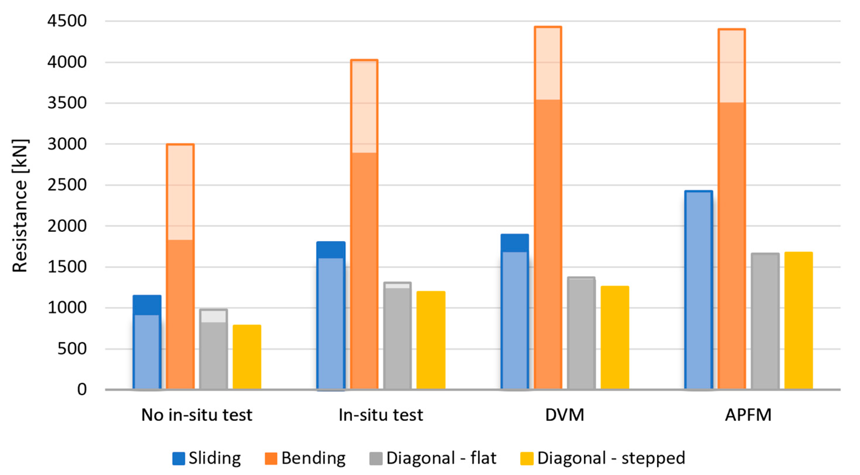
  • The calculated resistances increase with the increasing complexity of the methods used;
  • The observed differences in the results for the resistance of analyzed masonry wall obtained with different methods can vary from 48% to 161% depending on the failure mode;
  • Methods such as DVM and APFM can contribute to a more efficient and high-quality renovation of numerous existing masonry structures in earthquake-affected areas without unreasonably greater design efforts.

Author Contributions

Conceptualization, I.L. and D.S.; methodology, M.S. and L.L.; software, L.L.; validation, I.L. and D.S.; formal analysis, L.L.; investigation, M.S. and L.L.; resources, M.S.; writing—original draft preparation, L.L.; writing—review and editing, I.L., D.S. and M.S.; visualization, L.L.; supervision, I.L., D.S. and M.S.; funding acquisition, M.S. All authors have read and agreed to the published version of the manuscript.

Funding

This research was funded by the Croatian Science Foundation, grant number UIP-2019-04-3749 (ARES project-Assessment and rehabilitation of existing structures–development of contemporary methods for masonry and timber structures), project leader: Mislav Stepinac.

Data Availability Statement

The data presented in this study can be shared on request from the corresponding author.

Conflicts of Interest

The authors declare no conflict of interest.

References

  1. Gu, J.-B.; Tao, Y.; Xin, R.; Yang, Z.; Shi, Q.-X. Seismic Performance of Multistorey Masonry Structure with Openings Repaired with CFRP Grid. Adv. Civ. Eng. 2018, 2018, 4374876. [Google Scholar] [CrossRef]
  2. Canditone, C.; Diana, L.; Formisano, A.; Rodrigues, H.; Vicente, R. Failure Mechanisms and Behaviour of Adobe Masonry Buildings: A Case Study. Eng. Fail. Anal. 2023, 150, 107343. [Google Scholar] [CrossRef]
  3. Bernardo, V.; Sousa, R.; Candeias, P.; Costa, A.; Campos Costa, A. Historic Appraisal Review and Geometric Characterization of Old Masonry Buildings in Lisbon for Seismic Risk Assessment. Int. J. Archit. Herit. 2022, 16, 1921–1941. [Google Scholar] [CrossRef]
  4. Blagojević, P.; Brzev, S.; Cvetković, R. Seismic Retrofitting of Mid-Rise Unreinforced Masonry Residential Buildings after the 2010 Kraljevo, Serbia Earthquake: A Case Study. Buildings 2023, 13, 597. [Google Scholar] [CrossRef]
  5. Bilgin, H.; Leti, M.; Shehu, R.; Özmen, H.B.; Deringol, A.H.; Ormeni, R. Reflections from the 2019 Durrës Earthquakes: An Earthquake Engineering Evaluation for Masonry Typologies. Buildings 2023, 13, 2227. [Google Scholar] [CrossRef]
  6. Kržan, M.; Bosiljkov, V. Compression and In-Plane Seismic Behaviour of Ashlar Three-Leaf Stone Masonry Walls. Int. J. Archit. Herit. 2023, 17, 829–845. [Google Scholar] [CrossRef]
  7. Šipoš, T.K.; Hadzima-Nyarko, M. Seismic Risk of Croatian Cities Based on Building’s Vulnerability. Teh. Vjesn. 2018, 25, 1088–1094. [Google Scholar] [CrossRef]
  8. Kišiček, T.; Stepinac, M.; Renić, T.; Hafner, I.; Lulić, L. Strengthening of Masonry Walls with FRP or TRM. Gradjevinar 2020, 72, 937–953. [Google Scholar]
  9. Wilson, R.; Szabó, S.; Funari, M.F.; Pulatsu, B.; Lourenço, P.B. A Comparative Computational Investigation on the In-Plane Behavior and Capacity of Dry-Joint URM Walls. Int. J. Archit. Herit. 2023, 2023, 2209776. [Google Scholar] [CrossRef]
  10. Tomić, I.; Penna, A.; DeJong, M.; Butenweg, C.; Correia, A.A.; Candeias, P.X.; Senaldi, I.; Guerrini, G.; Malomo, D.; Wilding, B.; et al. Shake-Table Testing of a Stone Masonry Building Aggregate: Overview of Blind Prediction Study. Bull. Earthq. Eng. 2023, 1–43. [Google Scholar] [CrossRef]
  11. EMS Comision Sismologica Europea. Escala Macro Sísmica Europea EMS-98; European Seismological Commission: Luxembourg, 1998; Volume 15. [Google Scholar]
  12. Hogan, L.S.; Giongo, I.; Walsh, K.Q.; Ingham, J.M.; Dizhur, D. Full-Scale Experimental Pushover Testing of an Existing URM Building. Structures 2018, 15, 66–81. [Google Scholar] [CrossRef]
  13. Xu, J.; Feng, D.; Mangalathu, S.; Jeon, J. Data-driven Rapid Damage Evaluation for Life-cycle Seismic Assessment of Regional Reinforced Concrete Bridges. Earthq. Eng. Struct. Dyn. 2022, 51, 2730–2751. [Google Scholar] [CrossRef]
  14. Krolo, J.; Damjanović, D.; Duvnjak, I.; Smrkić, M.F.; Bartolac, M.; Košćak, J. Methods for Determining Mechanical Properties of Walls. Gradjevinar 2021, 73, 127–140. [Google Scholar] [CrossRef]
  15. Ortega, J.; Stepinac, M.; Lulić, L.; García, M.N.; Saloustros, S.; Aranha, C.; Greco, F. Correlation between Sonic Pulse Velocity and Flat-Jack Tests for the Estimation of the Elastic Properties of Unreinforced Brick Masonry: Case Studies from Croatia. Case Stud. Constr. Mater. 2023, 19, e02467. [Google Scholar] [CrossRef]
  16. Tomazevic, M. Earthquake-Resistant Design of Masonry Buildings; Imperial College Press: London, UK, 1999; Volume 1, ISBN 978-1-86094-066-8. [Google Scholar]
  17. Albanesi, L.; Morandi, P. Lateral Resistance of Brick Masonry Walls: A Rational Application of Different Strength Criteria Based on In-Plane Test Results. Int. J. Archit. Herit. 2023, 17, 846–867. [Google Scholar] [CrossRef]
  18. Romão, X.; Bertolin, C. Risk Protection for Cultural Heritage and Historic Centres: Current Knowledge and Further Research Needs. Int. J. Disaster Risk Reduct. 2022, 67, 102652. [Google Scholar] [CrossRef]
  19. D’Ayala, D.; Speranza, E. Definition of Collapse Mechanisms and Seismic Vulnerability of Historic Masonry Buildings. Earthq. Spectra 2003, 19, 479–509. [Google Scholar] [CrossRef]
  20. Khafizova, A. Vernacular Architectural Preservation of Material and Spiritual Interconnected Cultural Heritage. J. Contemp. Urban Aff. 2018, 2, 10–19. [Google Scholar] [CrossRef]
  21. Ramírez Eudave, R.; Ferreira, T.M.; Vicente, R.; Lourenco, P.B.; Peña, F. Parametric and Machine Learning-Based Analysis of the Seismic Vulnerability of Adobe Historical Buildings Damaged After the September 2017 Mexico Earthquakes. Int. J. Archit. Herit. 2023, 2023, 2200739. [Google Scholar] [CrossRef]
  22. Vrouwenvelder, T.; Scholten, N. Assessment Criteria for Existing Structures. Struct. Eng. Int. 2010, 20, 62–65. [Google Scholar] [CrossRef]
  23. Szabó, S.; Funari, M.F.; Lourenço, P.B. Masonry Patterns’ Influence on the Damage Assessment of URM Walls: Current and Future Trends. Dev. Built Environ. 2023, 13, 100119. [Google Scholar] [CrossRef]
  24. Caspeele, R.; Sykora, M.; Allaix, D.L.; Steenbergen, R. The Design Value Method and Adjusted Partial Factor Approach for Existing Structures. Struct. Eng. Int. 2013, 23, 386–393. [Google Scholar] [CrossRef]
  25. Fib. Bulletin 80: Partial Factor Methods for Existing Concrete Structures; Recommendation Task Group 3.1; Fib: Lausanne, Switzerland, 2016. [Google Scholar]
  26. Sousa, H.; Sørensen, J.; Kirkegaard, P. Reliability Analysis of Timber Structures through NDT Data Upgrading Short Term Scientific Mission, COST E55 Action; Aalborg University: Aalborg, Denmark, 2010. [Google Scholar]
  27. Mohsenian, V.; Padashpour, S.; Hajirasouliha, I. Seismic Reliability Analysis and Estimation of Multilevel Response Modification Factor for Steel Diagrid Structural Systems. J. Build. Eng. 2020, 29, 101168. [Google Scholar] [CrossRef]
  28. Androić, B.; Dujmović, D.; Lukačević, I. Razlike u Procjeni Pouzdanosti Uobičajenih i Iznimnih Konstrukcija. J. Croat. Assoc. Civ. Eng. 2009, 61, 943–953. [Google Scholar]
  29. Domański, T.; Matysek, P. The Reliability of Masonry Structures—Evaluation Methods for Historical Buildings. Tech. Trans. 2018, 115, 91–108. [Google Scholar] [CrossRef]
  30. Schueremans, L.; Van Gemert, D. Reliability Analysis in Structural Masonry Engineering. In Proceedings of the IABSE Colloquium—Saving Buildings in Central and Eastern Europe, Berlin, Germany, 4–5 June 1998. [Google Scholar]
  31. Sykora, M.; Holicky, M. Probabilistic Model for Masonry Strength of Existing Structures. Eng. Mech. 2010, 17, 61–70. [Google Scholar]
  32. Skrzypczak, I.; Kujda, J.; Buda-Ożóg, L. The Use of Probabilistic Methods in Assessing the Reliability of Masonry Structures. Procedia Eng. 2017, 193, 160–167. [Google Scholar] [CrossRef]
  33. Lara, C.; Tanner, P.; Zanuy, C.; Hingorani, R. Reliability Verification of Existing RC Structures Using Partial Factor Approaches and Site-Specific Data. Appl. Sci. 2021, 11, 1653. [Google Scholar] [CrossRef]
  34. Holický, M.; Jung, K. Reliability Verification of an Existing Reinforced Concrete Slab. TCES 2019, 18, 11–14. [Google Scholar] [CrossRef]
  35. Grubišić, M.; Ivošević, J.; Grubišić, A. Reliability Analysis of Reinforced Concrete Frame by Finite Element Method with Implicit Limit State Functions. Buildings 2019, 9, 119. [Google Scholar] [CrossRef]
  36. Skejić, D.; Dokšanović, T.; Čudina, I.; Mazzolani, F.M. The Basis for Reliability-Based Mechanical Properties of Structural Aluminium Alloys. Appl. Sci. 2021, 11, 4485. [Google Scholar] [CrossRef]
  37. Rücker, D.W.; Hille, D.-I.F.; Rohrmann, D.-I.R. F08a Guideline for the Assessment of Existing Structures; Federal Institute of Materials Research and Testing (BAM): Berlin, Germany, 2006. [Google Scholar]
  38. EN 1990; Eurocode—Basis of Structural Design. European Committee for Standardization: Brussels, Belgium, 2002.
  39. Dujmović, D.; Lukačević, I.; Androić, B. Design of Structures According to EN 1990: Theory and Worked Examples; IA Projektiranje: Zagreb, Croatia, 2020. [Google Scholar]
  40. Diamantidis, D. Reliability Assessment of Existing Structures. Eng. Struct. 1987, 9, 177–182. [Google Scholar] [CrossRef]
  41. Tanner, P.; Lara, C.; Bellod, J.L.; Sanz, D. “The Plastic Cathedral”: Innovation to Extend the Service Life of a Heritage Structure. Struct. Concr. 2020, 21, 1425–1440. [Google Scholar] [CrossRef]
  42. Borri, A.; Corradi, M.; Castori, G.; De Maria, A. A Method for the Analysis and Classification of Historic Masonry. Bull. Earthq. Eng. 2015, 13, 2647–2665. [Google Scholar] [CrossRef]
  43. Croatian Parliment. Law on the Reconstruction of Earthquake-Damaged Buildings in the City of Zagreb, Krapina-Zagorje County and Zagreb County (NN 102/2020); Croatian Parliament: Zagreb, Croatia, 2020.
  44. ISO 13822; Bases for Design of Structures—Assessment of Existing Structures. ISO: Geneva, Switzerland, 2010.
  45. ISO 2394; General Principles on Reliability for Structures. ISO: Geneva, Switzerland, 2015.
  46. CEN/TS 17440:2020; Assessment and Retrofitting of Existing Structures. CEN: Brussels, Belgium, 2020.
  47. Diamantidis, D. JCSS: Probabilistic Assessment of Existing Structures; RILEM: Paris, France, 2001. [Google Scholar]
  48. EN 1990-2 CEN/TC 250/SC 10; “EN 1990-2 Basis of Structural and Geotechnical Assessment of Existing Structures” Working Draft. CEN: Brussels, Belgium, 2022.
  49. Konig, G.; Hosser, D. The Simplified Level II Method and Its Application on the Derivation of Safety Elements for Level I, CEB, Bulletin No. 147; Fib: Lausanne, Switzerland, 1982. [Google Scholar]
  50. HRN EN 1998-3:2011; Eurocode 8: Design of Structures for Earthquake Resistance—Part 3: Assessment and Retrofitting of Buildings (EN 1998-3:2005+AC:2010). NSAI: Dublin, Ireland, 2005.
  51. EN 1998; CEN/TC 250/SC 8, Final Document EN1998-3 NEN SC8 PT3, Working Draft. European Committee for Standardization: Brussels, Belgium, 2018.
  52. Joanna, K. Analysis of Limit State of Load Resistance and Reliability of Masonry Structures Made of AAC Blocks. MATEC Web Conf. 2019, 262, 02001. [Google Scholar] [CrossRef]
  53. Lulić, L.; Stepinac, M.; Bartolac, M.; Lourenço, P.B. Review of the Flat-Jack Method and Lessons from Extensive Post-Earthquake Research Campaign in Croatia. Constr. Build. Mater. 2023, 384, 131407. [Google Scholar] [CrossRef]
  54. Stepinac, M.; Lulić, L.; Damjanović, D.; Duvnjak, I.; Bartolac, M.; Lourenço, P.B. Experimental Evaluation of Unreinforced Brick Masonry Mechanical Properties by the Flat-Jack Method—An Extensive Campaign in Croatia. Int. J. Archit. Herit. 2023, 2023, 2208542. [Google Scholar] [CrossRef]
  55. HRN EN 1996-1-1:2012; Eurocode 6: Design of Masonry Structures—Part 1-1: General Rules for Reinforced and Unreinforced Masonry Structures (EN 1996-1-1:2005+A1:2012). CEN: Brussels, Belgium, 2005.
  56. Schueremans, L.; Van Gemert, D. Probability Density Functions for Masonry Material Parameters—A Way to Go? In Proceedings of the Structural Analysis of Historical Constructions—Possibilities of Numerical and Experimental Techniques; Lourenco, P.B., Roca, P., Modena, C., Agrawal, S., Eds.; Macmillan India Ltd.: New Delhi, India, 2006; pp. 921–928. [Google Scholar]
  57. Graubner, C.A.; Brehm, E. JCSS Probabilistic Model Code Part 3: Resistance Models. In Joint Committee 12th Draft on Structural Safety; JCSS: Zurich, Switzerland, 2011. [Google Scholar]
  58. Madrigal, J.M.P. Some Notes about Architecture, Urbanism and Economy. J. Contemp. Urban Aff. 2018, 2, 1–11. [Google Scholar] [CrossRef]
  59. Churilov, S.; Dumova-Jovanoska, E. In-Plane Shear Behaviour of Unreinforced and Jacketed Brick Masonry Walls. Soil Dyn. Earthq. Eng. 2013, 50, 85–105. [Google Scholar] [CrossRef]
  60. Hafner, I.; Kišiček, T.; Gams, M. Review of Methods for Seismic Strengthening of Masonry Piers and Walls. Buildings 2023, 13, 1524. [Google Scholar] [CrossRef]
  61. Acikgoz, E.K. Catching Up With BIM: A Curriculum Re-Design Strategy. J. Contemp. Urban Aff. 2018, 2, 40–48. [Google Scholar] [CrossRef]
  62. Sassu, M.; Stochino, F.; Mistretta, F. Assessment Method for Combined Structural and Energy Retrofitting in Masonry Buildings. Buildings 2017, 7, 71. [Google Scholar] [CrossRef]
  63. Valluzzi, M.R.; Saler, E.; Vignato, A.; Salvalaggio, M.; Croatto, G.; Dorigatti, G.; Turrini, U. Nested Buildings: An Innovative Strategy for the Integrated Seismic and Energy Retrofit of Existing Masonry Buildings with CLT Panels. Sustainability 2021, 13, 1188. [Google Scholar] [CrossRef]
  64. D’Urso, S.; Cicero, B. From the Efficiency of Nature to Parametric Design. A Holistic Approach for Sustainable Building Renovation in Seismic Regions. Sustainability 2019, 11, 1227. [Google Scholar] [CrossRef]
  65. Privitera, R.; La Rosa, D. Reducing Seismic Vulnerability and Energy Demand of Cities through Green Infrastructure. Sustainability 2018, 10, 2591. [Google Scholar] [CrossRef]
Figure 1. Masonry failure modes (a) shear sliding, (b) bending and (c) diagonal failure.
Buildings 13 02790 g001
Figure 2. Case study building (a) east facade and (b) ground floor plan.
Buildings 13 02790 g002
Figure 3. Flat-jack test setup for determining (a) vertical stress state, (b) modulus of elasticity and (c) shear strength.
Buildings 13 02790 g003
Figure 4. Emergency interventions taken to ensure the stability of (a) damaged vaults and (b) staircases.
Buildings 13 02790 g004
Figure 5. Assessment phases.
Buildings 13 02790 g005
Figure 6. Results for URM wall resistance according to the current EN 1998-3 and the new proposal for EN 1998-3.
Buildings 13 02790 g006
Table 1. Structural reliability methods adopted from [37].
MethodApproach
Allowable stressDeterministic
Plastic design
Partial safety factorsSemi-probabilistic
Analytical and numericalProbabilistic
Simulation
Table 2. Structural assessment levels for existing (masonry) structures adopted from [37].
LevelReliability Class
1only visual assessment of damage and methods like MQI [42]
2simple hand calculations
3simple small-scale model-based assessment with assumed mechanical properties from the literature (no in situ tests)
4more detailed large-scale model-based assessment with real mechanical properties obtained through detailed in situ tests
5assessment considering target reliability and modified parameters of the structure through VoI analysis or Bayesian updating
6probabilistic assessment through full probabilistic analysis (in situ tests)
Table 3. Target reliability indices for ultimate limit state adopted from [37].
Service LifeβConsequences of Failure
50 years2.3very low
50 years3.1low
50 years3.8medium
50 years4.3high
Table 4. Target reliability indices adopted from [38].
Service LifeβReliability Class
50 years3.31
50 years3.82
50 years4.33
Table 5. Equations for the resistance calculation for all four failure modes.
EN 1998-3 [50]New Proposal EN 1998-3 [51]
f v = f v 0 + μ σ d (7) V 1 , Rd = f v γ Rd L c t w (9)
V 1 , Rd = f v C F γ M L c t w (8)
f d = f m C F γ M (10) ν = N L t w f m (13)
ν = N L t w f d (11)
V 2 , Rd = L N 2 h 0 ( 1 1 , 15 ν ) (12) V 2 , Rd = 1 γ Rd L N 2 h 0 ( 1 1 , 15 ν ) (14)
V 3 , Rd = L t w f t γ M C F b 1 + γ M C F σ 0 f t (15) V 3 , Rd = L t w f t γ Rd b 1 + σ 0 f t (16)
/ V 4 , Rd = L t w γ Rd b ( f v 0 ( 1 + μ j ϕ ) + μ j 1 + μ j ϕ σ 0 ) (17)
where:
fv—shear strength of masonry;
fv0—initial shear strength of the masonry (independent of vertical force);
μ—coefficient of friction (tanφ), where φ is the angle of internal friction;
σd—design vertical compressive stress;
γM—partial safety factor for the material;
CF—confidence factor;
Lc—length of the masonry in compression;
tw—wall thickness;
L—wall length (total);
N—vertical compressive force;
h0 = h/2—the height of the inflexion point (fixed-fixed boundary conditions assumed);
h—height of the wall;
ν—normalized axial force;
fd—design compressive strength of masonry;
fm—compressive strength of masonry;
ft—tensile strength of masonry;
σ0—average vertical compressive stress (over the entire surface of the wall);
b—geometry factor (b = h/L, but in between 1 and 1.5);
γRd—partial safety factor;
µj—local coefficient of friction of the joint (can be taken as 0.6);
Ø—clamping coefficient.
Table 6. Assumed and measured geometrical and mechanical properties of the investigated wall.
Assumed Properties Measured Properties
h [m]5.255.25
h0 [m]2.632.63
L [m]1111
Lc [m]1111
b [/]11
tw [m]0.450.45
N [kN]22002970
e [m]1.11.1
M [kNm]24203267
V [kN]9201244
fvo [MPa]0.2 (0.16 *)0.22
μ [/]0.4 (0.5 *)0.45
σd [MPa]0.450.6
CF [/]1.351.0
γM [/]1.51.5
γRd [/]****
K [/]0.450.45
fb [MPa]1011
fm [MPa]2.51.93
ft [MPa]0.15 (0.114 *)0.15
μj [/]0.60.45
Ø [/]11
* values from the proposed new version of the EN 1998-3 standard [50]. ** γRd varies for every failure mode and knowledge level KLM (shear sliding KLM1-1.65, KLM3-1.35, bending KLM1-2.15, KLM3-1.65, diagonal flat KLM1-1.55, KLM3-1.35, diagonal stepped KLM1-1.7, KLM3-1.4) [51].
Table 7. Statistical information on the basic variables obtained by on-site testing and factors obtained with DVM.
VariableDistr.MeanCoVγmγRdγM = γm × γRd
fb [MPa]Lognormal110.441.171.041.22
fm [MPa]Lognormal1.930.161.061.041.10
fv0 [MPa]Lognormal0.220.291.141.251.43
μ [/]Lognormal0.450.381.111.251.39
Table 8. Statistical information on the basic variables obtained by on-site testing and factors obtained with APFM.
VariableDistr.MeanCoVγRd(β′)γRd(β″)wy
fb [MPa]Lognormal110.441.061.040.62
fm [MPa]Lognormal1.930.161.061.040.83
fv0 [MPa]Lognormal0.220.291.441.250.59
μ [/]Lognormal0.450.381.441.250.64
Table 9. Load-bearing capacity according to Phase I.
Phase I.EN 1998-3 [50]New Proposal of EN 1998-3 [51]
Shear sliding929 kN1147 kN
Bending3003 kN1822 kN
Diagonal flat975 kN810 kN
Diagonal stepped/783 kN
Table 10. Load-bearing capacity according to Phase II.
Phase II.In situ Test (EN 1998-3 [50])In situ Test (New Proposal of EN 1998-3 [51])
Shear sliding1617 kN1797 kN
Bending4030 kN2885 kN
Diagonal flat1310 kN1230 kN
Diagonal stepped/1195 kN
Table 11. Load-bearing capacity according to Phase III.
Phase III.In Situ Test (EN 1998-3 [50])In Situ Test (New Proposal of EN 1998-3 [51])
DVMAPFMDVMAPFM
Shear sliding1696 kN2426 kN1884 kN2426 kN
Bending4442 kN4406 kN3554 kN3483 kN
Diagonal flat1371 kN1660 kN1331 kN1660 kN
Diagonal stepped//1253 kN1673 kN
Disclaimer/Publisher’s Note: The statements, opinions and data contained in all publications are solely those of the individual author(s) and contributor(s) and not of MDPI and/or the editor(s). MDPI and/or the editor(s) disclaim responsibility for any injury to people or property resulting from any ideas, methods, instructions or products referred to in the content.

