1. Introduction
In many technical applications, above-ground steel tanks are used for the storage of various liquids or bulk materials. Such tanks have a relatively simple geometry. They consist of steel sheets that are bolted or welded together. Tanks are produced with various types of roofs or open-topped. Commonly, there is a risk of buckling under load due to tanks being made of thin steel sheets. For this reason, wind girders are mounted to the tanks. In the case of open-topped tanks, the risk of buckling is more significant due to negative pressures (suction), as mentioned by the authors Uematsu et al. [
1]. The girders are used to increase the tank’s stiffness and buckling capacity. In some cases, the girder is mounted only on the top of the tank. However, using more grinders is practical for increasing buckling capacity. The number of girders and their placement are determined by the design according to the specific type and location of the tank. It is necessary to provide the tank wall with a special coating, e.g., enameling, anti-corrosion coatings, or use stainless steel as a material. Potential corrosion also significantly reduces buckling capacity, which has been investigated by the authors Zhao and Lin [
2] and Shokrzadeh and Sohrabi [
3]. Another risk of buckling occurs during the construction of the tank, as discussed by Jaca and Godoy [
4], and therefore, recommended principles during construction should be followed.
Bolted tanks consist of sheets with drilled holes, which are also used for mounting the above-mentioned wind girders onto the tank wall. Each country defines the standards for the design of cylindrical above-ground tanks. The European single market is subjected to Eurocodes. For tank design, it is possible to use Eurocode 3 Part 4-2: Tanks [
5] and for loads Eurocode 1 Part 4: Loads on tanks and reservoirs [
6] together with others. AWWA D103-09 [
7] is the most commonly used standard for the design of bolted tanks in the American continent. When designing tanks, it is necessary to take into account in particular (I) the load from the storage medium, (II) the wind load, (III) the dead load, (IV) the snow load for roofed tanks, (V) the operating load, and (VI) possible seismic effects. In this paper, the authors focused on the use of Eurocodes and the wind load (II) because wind girders are mainly used to prevent buckling under wind action.
1.1. Procedures for the Evaluation of Tank Buckling Capacity
The load-bearing capacity of the tanks is mainly affected by the hydrostatic pressure load and seismic effects at low wind speeds—i.e., a full tank. Wind load greatly affects buckling capacity, especially for higher wind speeds and empty tanks. The bottom section of the tank usually has thicker sheets due to the higher hydrostatic pressure load, so the wind girders reinforce mainly the top section.
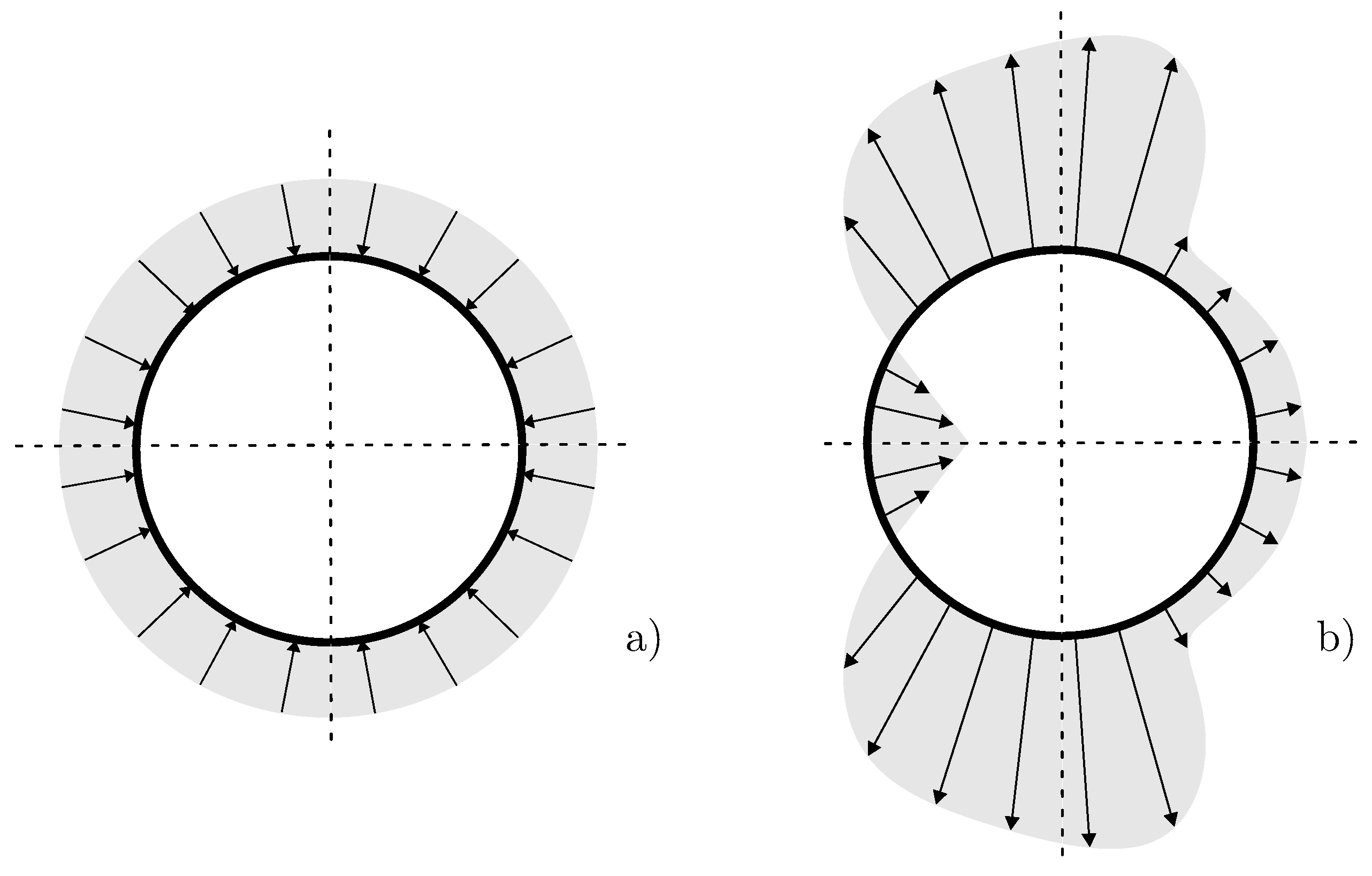
The wind load can be implemented in the numerical model using an equivalent axisymmetric pressure-idealized (see
Figure 1a) or the real pressure distribution based on the relevant standard, testing, or numerical simulation (see
Figure 1b). The Eurocode EN 1991-1-4 [
8] specifies a coefficient
to convert the real pressure distribution to the axisymmetric pressure. The substitution of this distribution is used by Uematsu et al. [
1]. The authors Zhao and Lin [
2] and Burgos et al. [
9] studied both types of wind pressure distribution, and according to their study, axisymmetric pressure is conservative for the buckling of tanks. However, this simplified pressure distribution is only used for analytical designs or initial analyses.
Tanks can be classified as thin-walled structures; therefore, membrane theory can be used to evaluate tank limit states. Membrane theory is an analysis that predicts the behavior of thin-walled structures under continuous loading, assuming only membrane forces in equilibrium with the external load. The assumptions of membrane theory are published in the literature [
10] and cannot account for many real cases. In current practice, numerical models using the shell theory with different accuracy are used. Types of the shell theories specified in EN 1993-1-6 [
11] are listed in
Table 1. Four limit states, which should be considered when evaluating tanks according to EN 1993-1-6, are
Because this paper is focused on wind girders, the authors mainly dealt with the buckling of tanks. According to EN 1993-1-6, buckling is defined as
“the limit state at which the structure suddenly loses stability under membrane compression or shear”. For these tank analyses, numerical models using the finite element method (FEM) are most commonly used. The least accurate and unsuitable in relation to the stability of thin-walled structures is linear elastic shell analysis (LA). The implementation of LA using a numerical model was studied by Kminek et al. [
12]. The most accurate results are given by geometrically and materially non-linear analysis with imperfections (GMNIA).
Elkholy et al. [
13] investigated the use of six different shell elements in Ansys Mechanical (Ansys, Canonsburg, PA, USA) for tank analysis considering structure–fluid–soil interaction. They used the experimental model and theoretical solution obtained by Mazuch et al. [
14] to validate the numerical results. Two cases, an empty and a filled tank, were tested. The performed analyses showed that the number of elements significantly affects the accuracy of obtained results.
A parametric study for four different large-capacity open-topped tanks was presented by Pan and Liang [
15]. They performed linear and non-linear numerical analyses with imperfections. The results show that the main effect on the buckling under wind action is due to the pressure of the windward side, and the use of girders can significantly increase buckling capacity. Chen and Rotter [
16] performed an analysis of cylindrical shells with uniform thickness. They considered a stocky cylinder, an intermediate cylinder, and a slender cylinder. In their paper, they found that different dimensionless length parameters play the main role in buckling capacity, and plasticity has a minor role for cylinders with
500. Cao and Zhao [
17] carried out a parametric study on the buckling capacity of filled silos with various slendernesses. They applied an axisymmetric pressure, which allowed them to simplify the model of the tank. They performed six different linear and non-linear analyses to study buckling capacity. The analyses showed that material non-linearity strongly influences the behavior of all selected tank slendernesses. The distribution of the wall thickness over the height of the tank also has a significant additional influence on buckling capacity. However, the study by Zhao et al. [
18] described that material non-linearities have only a relevant effect when modeling the buckling of a filled tank. In the case of an empty tank, this effect is negligible. However, the implemented imperfections have a significant effect, which reduces buckling capacity in both cases. For this reason, linear bifurcation analysis (eigenvalue buckling) is suitable as an initial indicator of buckling capacity. Eigenvalue buckling shape should be used as imperfections for the following non-linear analysis, which is also recommended by Maraveas et al. [
19].
Dynamic analysis of open-topped tanks has been discussed by Chiang and Guzey [
20], who performed a modal analysis and obtained mode shapes and natural frequencies. Modal analysis of tanks is important to determine a critical wind speed. The critical wind speed occurs when the vortex shedding frequency is close to the natural frequency of the tank. To estimate the vortex shedding frequency, the Strouhal number is used. Strouhal number is a dimensionless number, which gives the ratio of vortex shedding frequency multiplied by characteristic dimension and flow velocity. A more detailed description of vortex shedding and the Strouhal number for cylinders is given in the publication by the authors Alam and Zhou [
21]. An experimental determination of the Strouhal number in a wind tunnel was performed by the authors Ellingsen et al. [
22].
Shokrzadeh and Sohrabi [
3] investigated the effect of corrosion on buckling. In their paper, they considered both cases of wind pressure distribution and observed that in the case of non-uniform pressure distribution, the effect of corrosion is more significant. The distribution of the wind pressure acting on the tank is also influenced by whether it is an isolated tank or several tanks located close to each other. The effect of several tanks placed behind each other with different distances between them has been studied by Godoy [
23] or also Burgos et al. [
24].
1.2. Description of Wind Girders
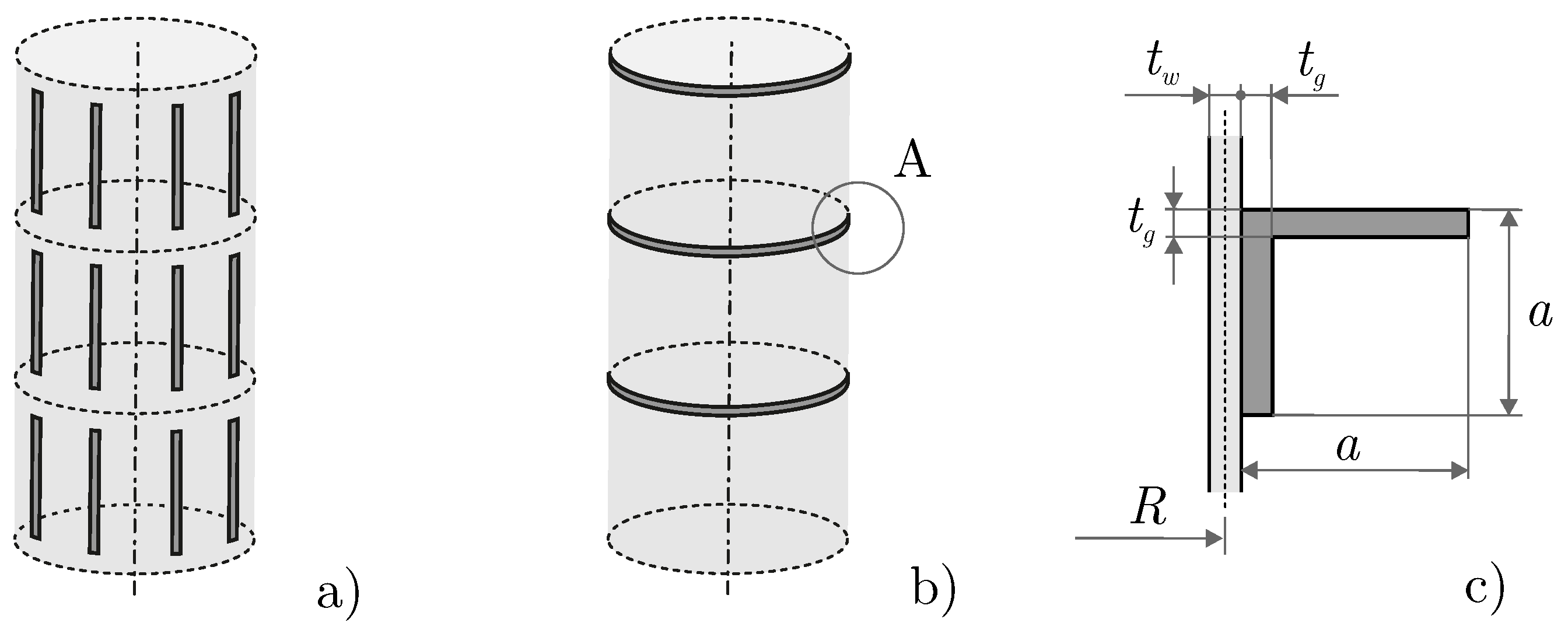
In engineering applications, stiffeners are divided into vertical and horizontal, as shown in
Figure 2. Vertical stiffeners (see
Figure 2a) are mainly used to increase stiffness in the lower part of the tank or areas with high axial loads. However, these stiffeners are not used very often because of their efficiency. Horizontal stiffeners (
Figure 2b) are used to reinforce the tank due to wind action and to prevent buckling. Therefore, they are called wind girders. Wind girders usually take the form of round-edged steel bars of various dimensions, as illustrated in detail A of
Figure 2c. These girders are mounted on the top of the tank and eventually between selected rows of the tank wall. The location and dimensions of the girders are specified in the design process. The use of appropriate girders, including their correct placement, increases the buckling capacity of the tanks, which was also confirmed by the authors Pan and Liang [
25]. Standard EN ISO 28765 [
26] defines the minimum moment of inertia to be used for the upper girder and also for the intermediate girders, depending on their spacing, the loads, and the dimensions of the tank. In the case of conventional girders, the moment of inertia (as well as the stiffness) of the girder is uniform around the circumference of the tank. The dimensions of the girders can be thus easily determined. The most common placement of girders is the upper part because the thinnest sheets are usually placed from the upper edge.
Conventional girders with uniform cross-sections are not very efficient in terms of production technology, especially for large cross-sections of girders or large curvature of tanks. Uematsu et al. [
1] have analyzed the stiffness of girders and they show that there is a limiting “stiffness” value of girders. When increasing the stiffness of the girder above the limit value, there is no longer a noticeable increase in buckling capacity. The aspect ratio of the tank and whether the bottom of the tank affects the overall stiffness also matter when designing girders, which was discussed by Bu and Qian [
27]. The use of intermediate girders changed the single-mode shapes during buckling and also increased buckling capacity. The study of the geometrical parameters of the girders was carried out by Bu and Qian [
28] and Lewandowski et al. [
29]. The authors’ findings can be summarized that the design of the dimensions of the girders specified in the standards is conservative. And detailed non-linear analysis is recommended for better use of the material, taking into account all possible factors.
1.3. Possibilities of New Girders Design
As mentioned above, wind girders have a significant effect on the behavior of tanks, especially for buckling. The stiffness requirements for wind girders in open-top tanks were published by the authors Zebyek and Topkaya [
30]. They propose a minimum requirement for the second moment of area with respect to negative internal pressure (suction). The possibility of replacing the girder with various modifications and the usage of boundary conditions was studied by Burgos et al. [
9]. By designing the optimal type and placing them correctly, buckling capacity can be greatly increased. The main idea of the new shape of the girder is the use of a simple profile (segment) with a rectangular cross-section, which is intricately curved around the circumference of the tank. The new girder design is composed of many segments mounted together around the circumference of the tank. The bend of the segment easily adapts to different tank diameters, and these new profiles are easy to store for use on any tank. For this reason, it is easier to manufacture and customize. The total cost of tank construction (after accounting for production costs) is thus reduced. The new girder shape is used experimentally by several companies, but it is not possible to get details of the geometry, overlapping of the sheets, and design data. The new shape also needs to be customized to the sheet metal punching and designed to the producer’s requirements.
The behavior of the new girders, especially ones with variable moment of inertia around the circumference of the tank, is required to be analyzed using a numerical model. The girders are mainly designed to resist wind load. This means that it is necessary to assess the condition in the case of an empty tank and the application of external pressure. The axisymmetric pressure around the circumference of the tank is conservative for buckling; therefore, this pressure distribution is considered in this paper.
This paper aims at the non-linear modeling of a new type of horizontal wind girder concerning the above-mentioned disadvantages of profiles with uniform cross-sections. For this purpose, a numerical model of the tank with the new type of girder is designed. The numerical model consists of buckling analyses (using GMNIA) and modal analyses for various tank dimensions. By using a more efficient and reliable shape of the girder, the cost of the tanks is reduced through easier production technology. Preliminary results were published by the first author of this paper in his master’s thesis [
31].
2. Materials and Methods
This section is divided into 3 parts. In the first part, a description of the design of the new wind girder (NWG) is presented. In the second part, the numerical model of the tank is designed. This part focuses on the material model, boundary conditions, and solution assumptions. To study the behavior of the new design, buckling capacity of the tank with NWG is compared with the tank with round-edged equal leg steel angle bar EN 10056-1 [
32] - L60 × 60 × 6 - EN 10025-2 [
33]—corresponds to
mm,
mm (L60) (see
Figure 2c). Replacement of L60 is selected based on experience of the company WITKOWITZ ENVI a.s. The same material-steel S235JR EN 10025-2—is considered for NWG and L60. In the third part, a parametric study of low-height to high tanks is presented.
2.1. Design of New Wind Girder
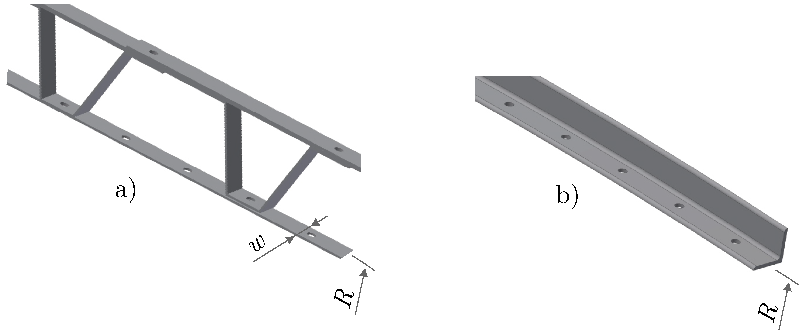
The innovation in NWG compared to the conventional girder is the use of two differently curved thin sheets (V-segment and P-segment) adapted to the tank wall (tank radius is
R). A shape of NWG formed by segments is shown in
Figure 3a. The illustrated holes are intended for mounting bars or segments to the tank wall. The displayed configuration is repeated around the circumference of the tank, and thus the whole girder is formed. The shape of a conventional girder is shown in
Figure 3b. The bar of the given length is bent to the required curvature, and then it is mounted to the tank using the depicted openings.
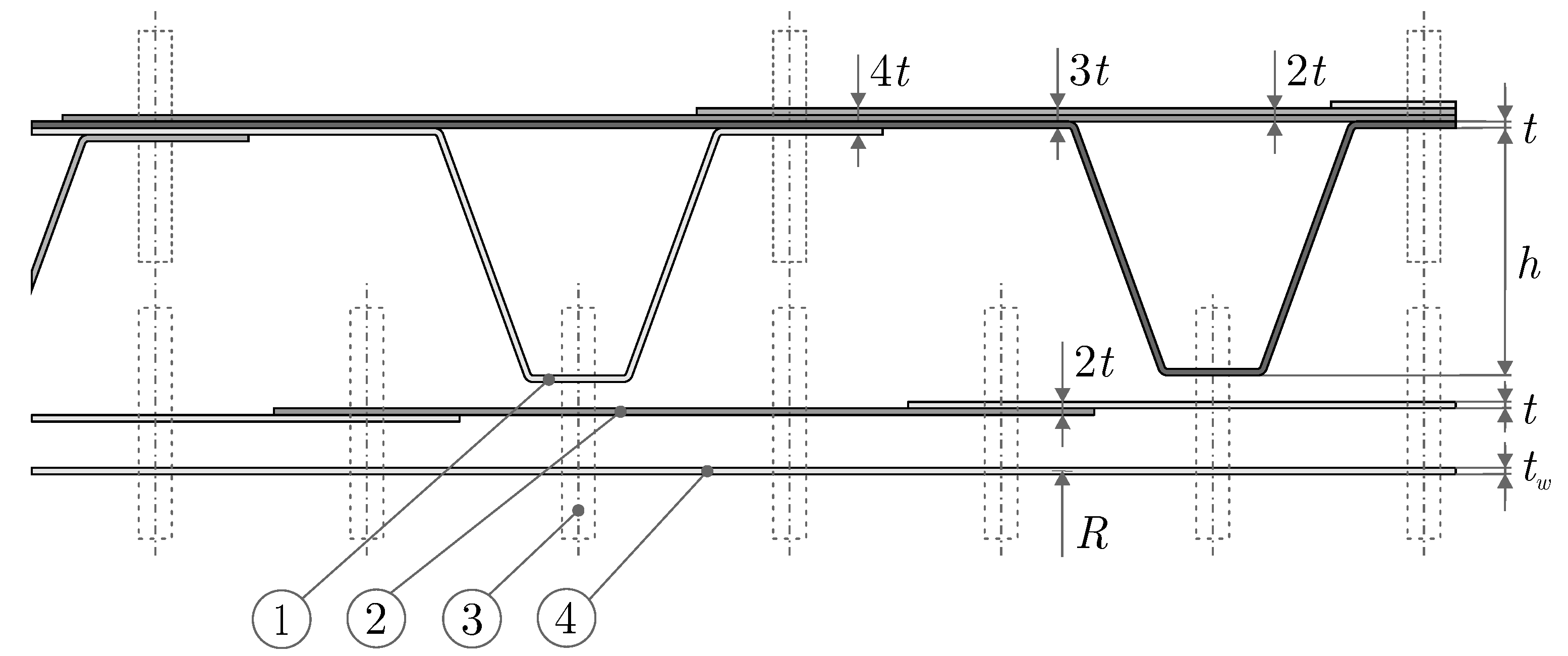
The detail of NWG is shown in
Figure 4. The V-shape segment of height
h (Item 1) is further supplemented by the plate (P-segment) of the same thickness
t and width
w (Item 2). The segments are further bolted (Item 3) together and attached to the tank wall (Item 4) to form a trapezoidal girder shape. All these segments have a simple rectangular cross-section, but by overlapping each other, the thickness is strengthened. This effect leads to a local increase in the moment of inertia. According to the designed geometry, the thickness is increased up to four times in some regions.
During manufacturing, distortion of the V-segment and the P-segment does not occur as in conventional profiles. In the case of insufficient rigid girders in the design of the structure, the stiffness of the girder can be easily increased by modifying the selected parameters (especially h and t), and thus a higher buckling capacity can be achieved. Therefore, it is possible to manufacture many segments of NWG according to tank size for efficient mass production.
Standards for designing bolted tanks define the minimum moment of inertia or the section modulus of the wind girders [
7,
26]. The main difference in the new shape is the fact that NWG does not have a uniform moment of inertia in the circumferential direction like conventional profiles. For this reason, it is advisable to investigate the behavior of the girder by using a numerical model for a reliable design. The proposed basic dimensions of the segment forming NWG are listed in
Table 2. Dimensions are designed using a numerical model and adapted to the manufacturer’s structural capabilities.
2.2. Design of Non-Linear Numerical Model
Large-capacity tanks can be considered as thin-walled structures, satisfying the condition
10, where
R is the radius of the tank, and
is the thickness of the tank wall. For buckling capacity study, geometrically (large deflections and strains) and materially non-linear analysis with imperfections (GMNIA) under external pressure is performed. To implement the imperfections, linear elastic bifurcation analysis (LBA) was used. Displacements in each node were exported, and further, this mesh was imported as an initial shape in GMNIA. The imperfection amplitude was applied to
. The influence of the imperfection amplitude has been studied by many authors [
2,
15,
24,
34]. In this paper, a sensitivity study of imperfection amplitude was performed for three variants with NWG (TK1, TK4, and TK7), which varied a lot from the model with L60. Results of this study are presented in
Section 3.5. Further, a modal analysis (MA) of all investigated tank types was performed. The mode shapes and natural frequencies are important factors as they can affect the possible vibrations of the tanks during airflow and vortex shedding. The natural frequencies of the tank should be sufficiently different from the vortex shedding frequency. The authors of this paper have many years of experience in the application of numerical methods to solve the behavior of complex structures [
35,
36,
37,
38,
39]. For this reason, the authors used FEM and designed a parametric numerical model of the tank in ANSYS Workbench 2022 R2 (Ansys, Canonsburg, PA, USA).
A 3D numerical model combines two types of finite elements (shell and beam elements are used). A 4-node shell element SHELL181 with linear displacement approximation using 6 degrees of freedom per node (3 displacements and 3 rotations) is used for the discretization of the tank wall. The girders are modeled using the 2-node beam element BEAM188 with linear displacement approximation using 6 degrees of freedom per node (3 displacements and 3 rotations). Because applied element types (shells and beams) use the same number of degrees of freedom, the connection of these elements is achieved through the node merge. To simplify a girder model, different cross-sections are defined for each part with different shapes. For the V-segment are defined rectangular cross-sections from 50 × 4 mm to 50 × 12 mm according to different thicknesses of the shape in
Figure 4. Thus, a different number of the overlapped sheets is taken into account, and it is not required to use the mutual contacts of the individual segments. The P-segment is modeled as an additional thickness of the tank wall so that a rigid connection between the segment and the tank is defined. Due to low stiffness at the top edge of the tank, for the upper girder, the number of P-segments is doubled. For numerical model with L60 is defined as a beam with a uniform cross-section 60 × 60 × 6 according to
Figure 2c.
Because in this paper a parametric study was carried out for different tank sizes (see
Section 2.4), the finite element mesh parameters are given for multiple models. A sensitivity analysis of the mesh size influence on buckling capacity was performed. Therefore, the shell element edge length in the circumferential direction is set to 32.5 mm for all variants. Element size in axial direction varies for each variant and is between 25 mm for small tanks and 150 mm for large tanks. In the case of L60, the beam element length is the same as the shell element length in the circumferential direction. In the case of NWG, the beam element length varies. The connection part to the tank wall of the V-segment is divided into two elements, and the element length of the remaining parts depends on the size of the overlap of sheets and dimensions of the segment (see
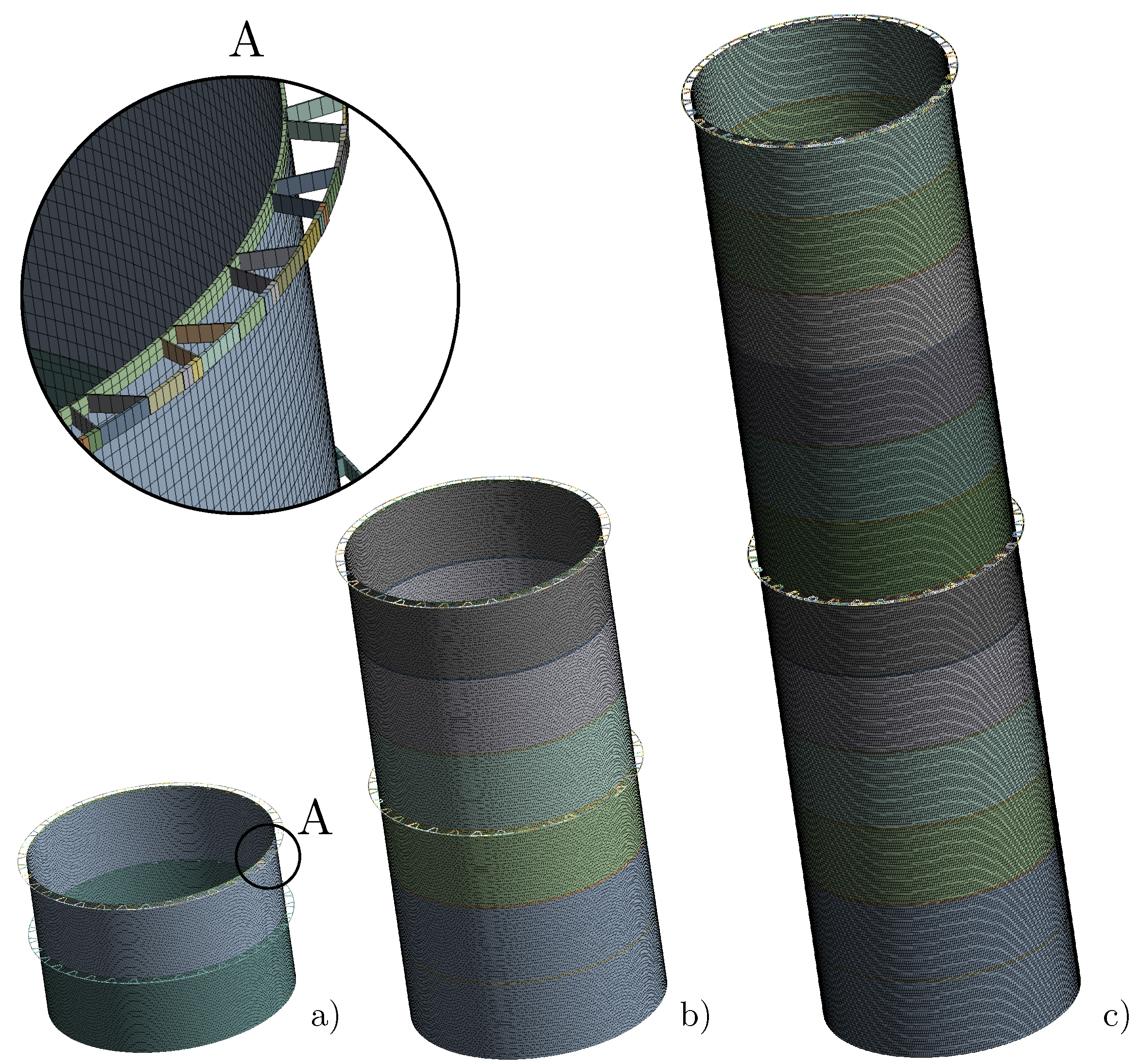
Figure 4). However, the preferred length of these parts is set to 32.5 mm. The total number of nodes of the finite element mesh of the model with NWG ranged from 28,815 to 598,640 nodes. For cases with L60, the number of nodes is a bit lower due to simpler geometry, but similar to variants with NWG. The finite element meshes for a model with an NWG and a diameter of 4.3 m are shown in
Figure 5. Detail A shows detailed connections of nodes of tank wall and girder, which was performed by node merge in the appropriate places. One can also observe the single cross-sections of NWG, which are discretized by beam elements.
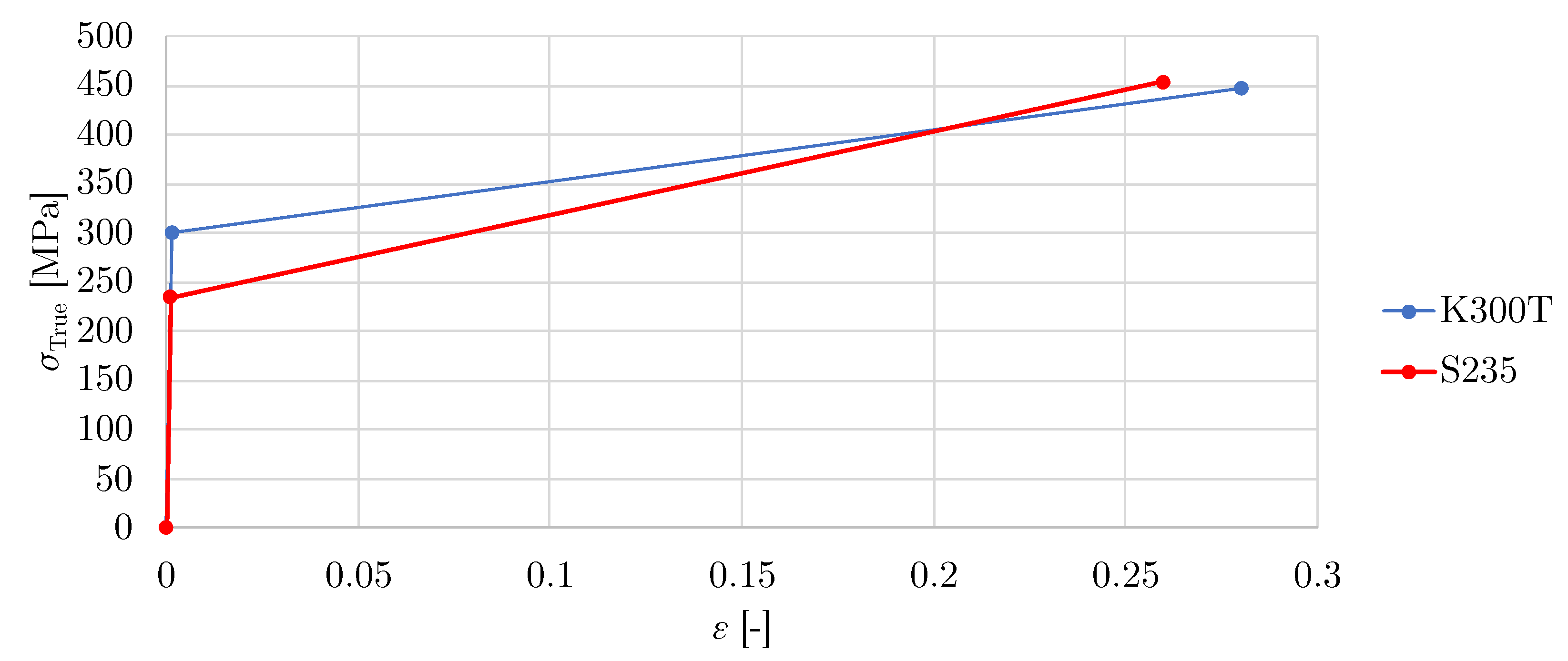
The tank wall and girders materials are considered to be ideally isotropic and homogeneous. The yield stress is typically greater for the tank wall material than for the girder material because the tank wall is usually more loaded. For girders, the yield stress and the tangent modulus play a minor role. A bilinear elastoplastic material model with isotropic hardening was used for both materials. Relation between true stress
and deformation
is in
Figure 6. The elastic part is defined by Young’s modulus
E and Poisson’s ratio
. The plastic part is from yield stress
to ultimate stress
with tangent modulus
. The tangent modulus
is calculated from the elongation and ultimate stress. Young’s modulus and Poisson’s ratio are taken as standard values for conventional structural steels specified in Eurocode EN 1993-1-1 [
40]. For the tank wall, KOSMALT E 300 T (K300T) is selected with the mechanical properties given in the U. S. Steel Košice catalog [
41]. The girder material is chosen S235JR EN 10025-2 (S235) with the mechanical properties given in Eurocode EN 1993-1-1 [
40]. The material constants used for the tank wall and girders are given in
Table 3.
To determine buckling capacity, axisymmetric pressure distribution around the tank circumference (see
Figure 1a) is gradually applied. The axisymmetrical load pressure is prescribed in the range from
0.2–50 kPa depending on the dimensions of the tanks. The full Newton–Raphson method is applied to solve the non-linear model. The number of minimum executed substeps of the Newton–Raphson method is set to 100 and the maximum substeps to 100,000 for all variants. Maximum displacement corresponding to the current pressure level is determined in each substep. From this relation (displacement vs. pressure) are determined the slopes
k and their relative deviations
At the moment when deviation
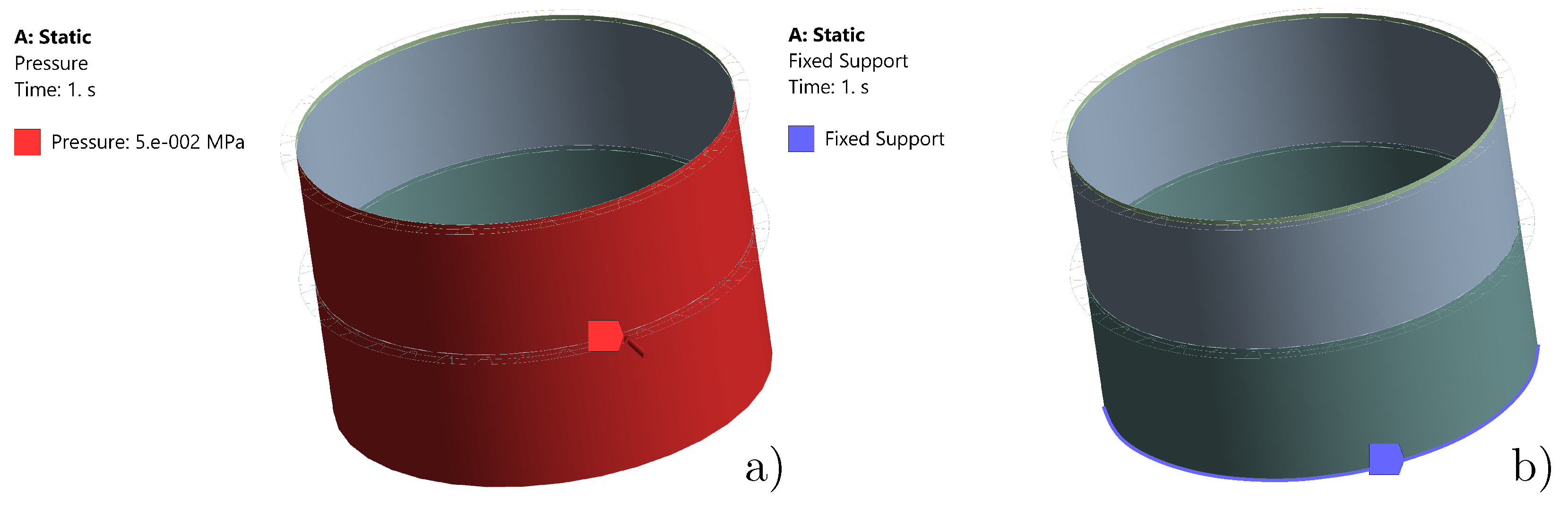
is not positive or the method fails to converge, the buckling capacity of the tank is assumed to be reached. The critical pressure corresponds to buckling capacity, which is obtained as the previous substep. Typically, the tanks are anchored to a concrete foundation; therefore, fixed support is used at the bottom of the tank to eliminate displacement and rotation of the nodes at the bottom edge of the tank. Only the empty tank case is considered in the whole study, as in this case, there is a higher risk of buckling due to external pressure. The self-load of the tank and the girders is neglected as it has only a minimal effect on the given configuration. Applied boundary conditions are shown in
Figure 7. The maximum value of pressure for this variant was prescribed to 50 kPa (see
Figure 7a). The bottom edge of the tank wall was fixed as is shown in
Figure 7b.
2.3. Analytical Models According to European Standards
This section presents a view on the issue of tank buckling concerning two methods of critical pressure assessment according to European standards. The following simplified analytical models were used in the next section to compare with numerical models. The first way is to evaluate the buckling according to the EN 1993-1-6 [
11]. In this evaluation, the wind and subsequent external pressure have a major role in circumferential stress. According to this standard, the critical pressure using membrane theory
can be determined from the limiting value of the circumferential stress
(mainly a function of tank geometrical dimensions and position of girders, production quality, or size of imperfections and material mechanical properties). For comparison purposes, quality class A according to EN 1993-1-6 was selected in the results presented in
Section 3.4.
Another possibility is the use of EN ISO 28765, where the limit external pressure is explicitly defined using Donnell’s theory. This limit value is a function of Young’s modulus, Poisson’s ratio, wall thickness, distance between girders, and tank radius. However, the size of imperfections does not appear as a separate parameter that could be easily changed in this formula.
2.4. Parametric Study
A parametric study is performed on selected tanks to analyze the behavior of the girders under axisymmetrical pressure acting on an empty tank. Three different diameters
D and three different tank heights
H for each diameter are taken, as listed in
Table 4. Tank wall thickness
= 3 mm is considered. The range of tanks
D = 4.3–42 m and
H = 2.9–17.2 m is chosen based on the selection from the production list of the company WITKOWITZ ENVI a.s. The considered tank dimensions with mesh statistics and number of segments (V-segment + P-segments) per girder are listed in
Table 4.
To analyze NWG behavior, the numerical model including L60 girders is designed. The model has the same mesh for the tank wall but the mesh of the girder is different due to geometry. For the reference numerical model, girders with a standardized profile are used and placed in the same positions as the new girder shape. The girders are placed above the top ring of the tank and between the middle rings. This distribution is only for comparison purposes and does not respect the design distances between the girders or dimensions according to the relevant standards. The critical pressure and associated shape from GMNIA are evaluated in both models. From the modal analysis, the first natural frequency with the corresponding mode shape is evaluated.
3. Results
This section summarizes the results of the behavior of NWG by the parametric study using GMNIA and MA. The calculated results are divided into three categories according to the height of the tanks with NWG compared with L60. The evaluated parameters are: critical pressure for the model with L60 , first natural frequency for the model with L60 , critical pressure for the model with NWG , first natural frequency for the model with NWG , maximum equivalent stress (HMH) in tank wall and girder for model with L60 and maximum equivalent stress (HMH) in tank wall and girder for model with NWG. In addition, the relative deviation between the standardized profile and the new shape for both variables is listed.
3.1. Application of New Wind Girder to Low-Height Tanks
The first evaluated set is for the low-height tanks with height
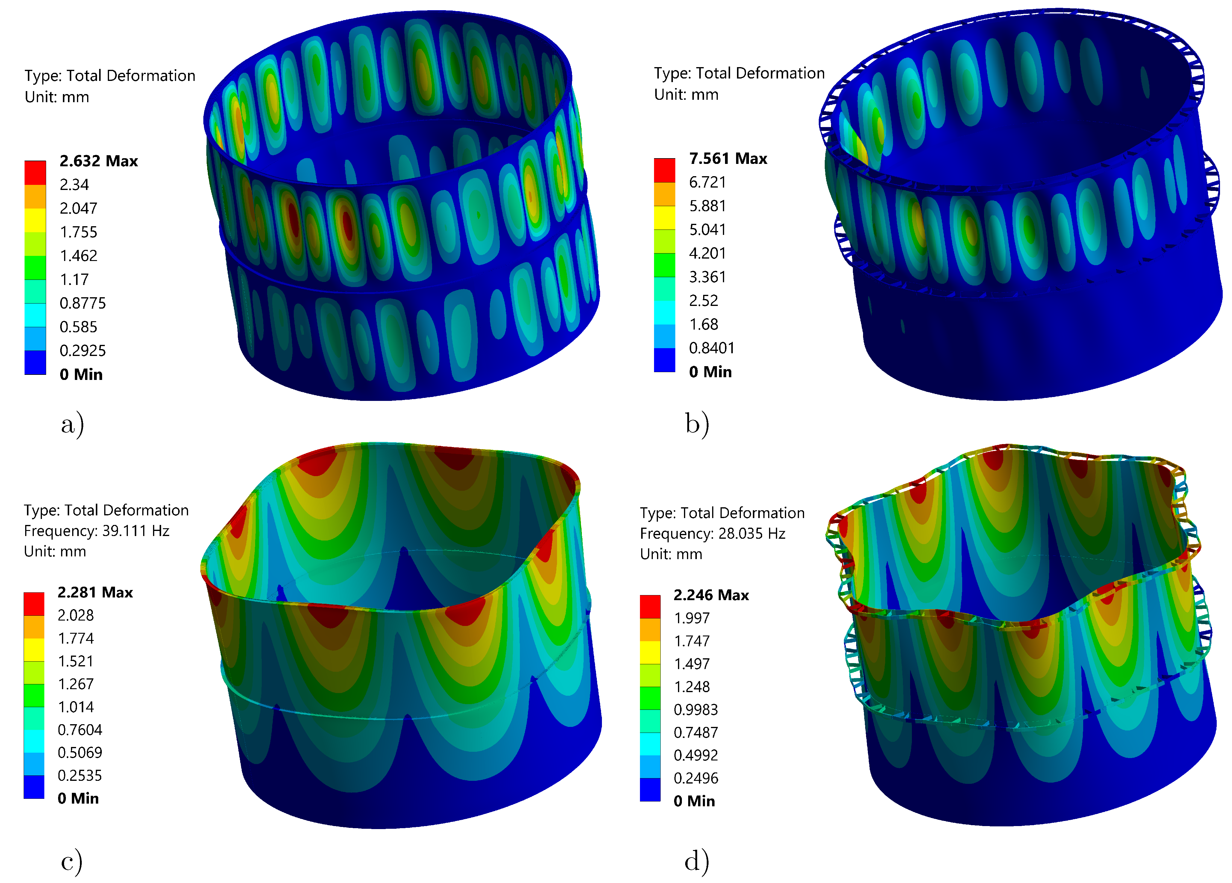
= 2.9 m (TK1, TK2, and TK3). The results obtained for TK1 presented as shape under critical pressure from GMNIA and also the first mode shape from MA for both types of girders are shown in
Figure 8.
The results show that shapes obtained from GMNIA are slightly different and total deformation is significantly higher for the NWG model. The value of critical pressure obtained from the GMNIA is also higher for the model with L60 and is given in
Table 5. Mode shapes from MA are quite different for both models too. This is also associated with the values of the first natural frequencies, where for the model with L60, the first natural frequency is
= 39.111 Hz, and the model with NWG is much lower
= 28.035 Hz.
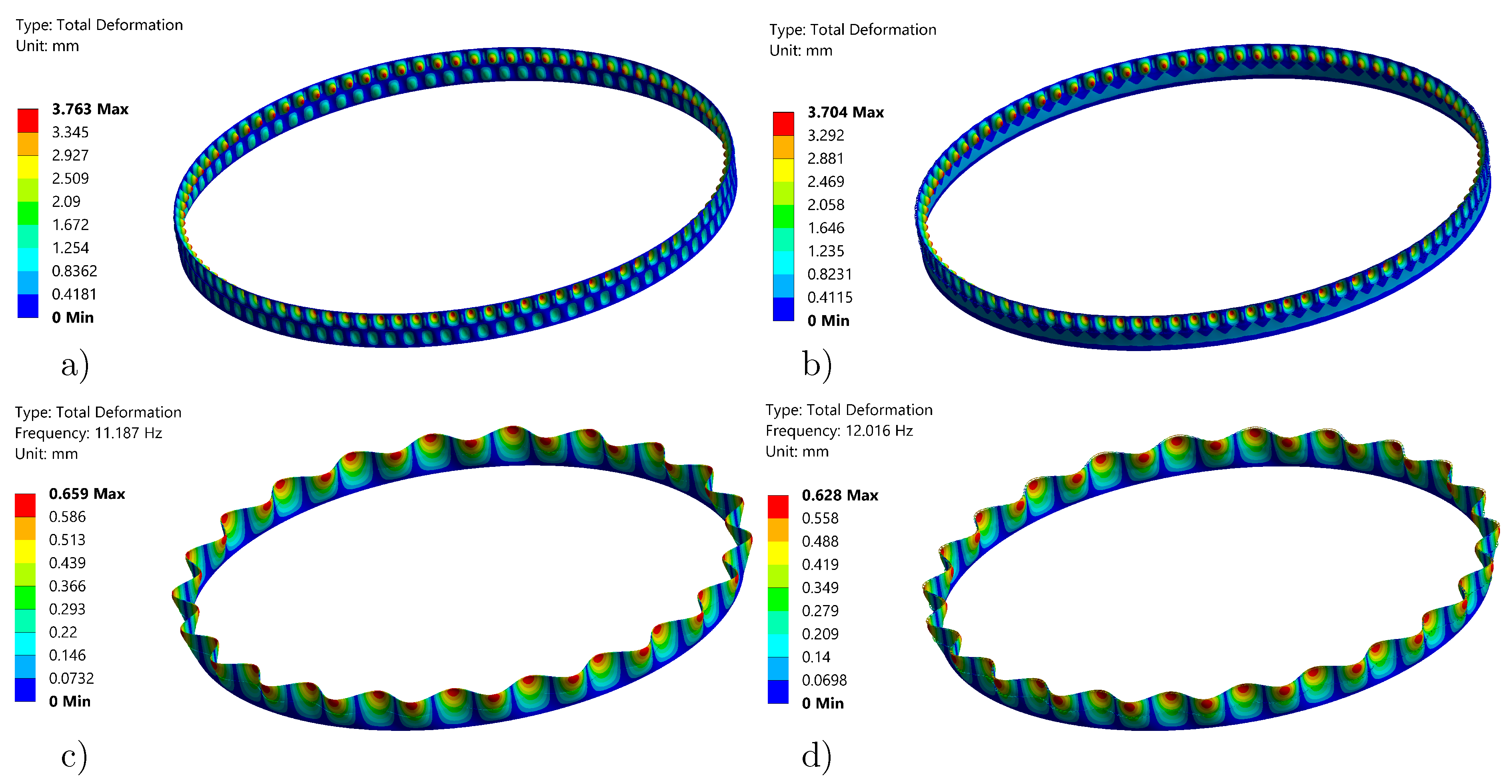
In the case of the larger diameter tanks (TK2 and TK3), the natural frequencies of both models decrease and also get closer to each other. The results for the TK3 variant are shown in
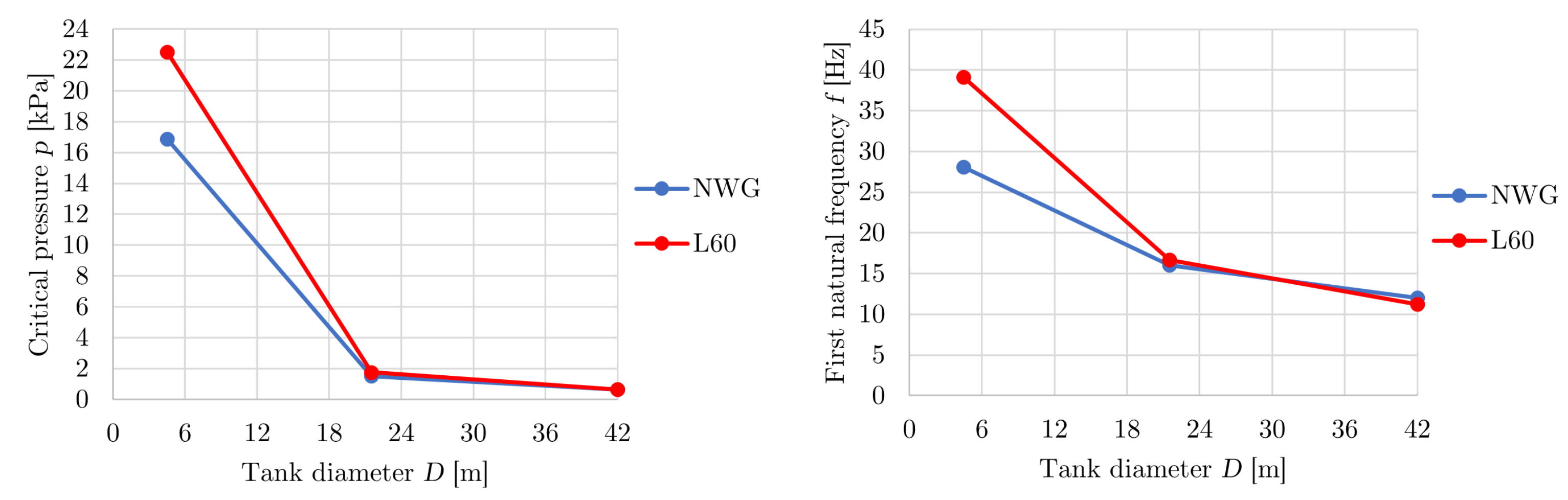
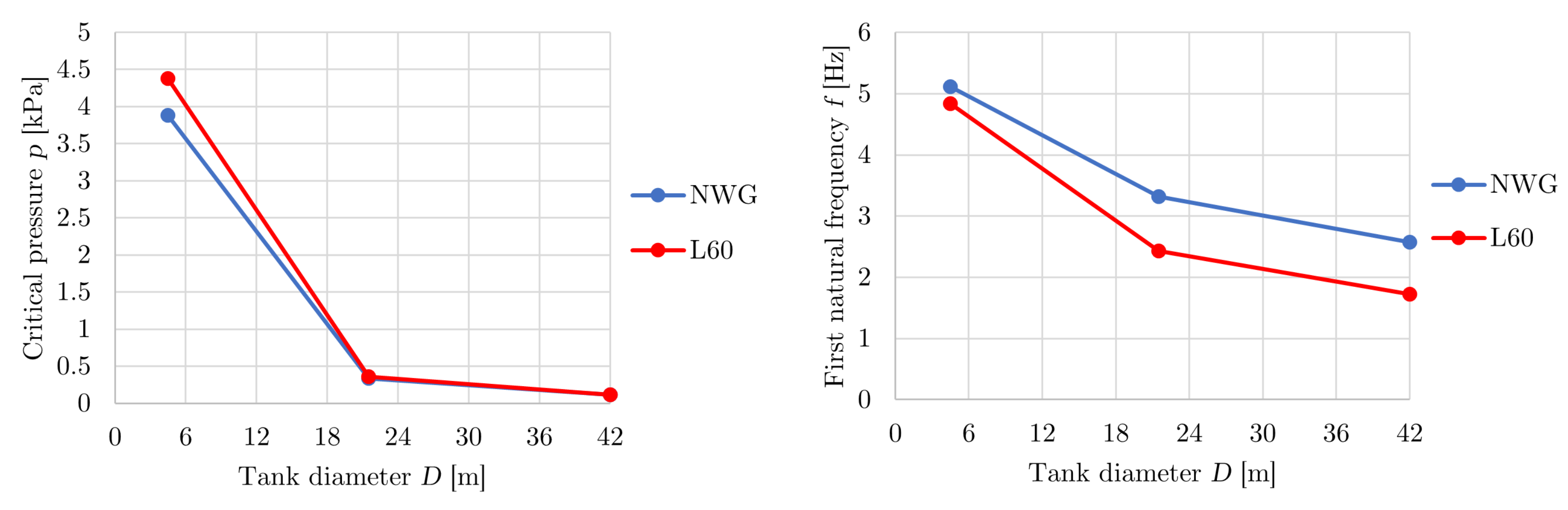
Figure 9. As one can observe from the figure, the mode shapes are already comparable, although the natural frequency is slightly higher in the case of the model with NWG. Shapes at buckling from GMNIA are similar to TK1, but maximum deformation in this case is close to each other. Maximum deformation is also more concentrated in the upper part of the model with NWG, similar to TK1. The comparison of critical pressure and first natural frequency plotted as a function of tank diameter for the low-height tanks is shown in
Figure 10. From the plotted comparison, it is obvious that both the critical pressure and the first natural frequency decrease with increasing diameter, and the biggest differences are in variant with diameter
D = 4.3 m (TK1).
3.2. Application of New Wind Girders to Middle-Height Tanks
For the middle-height tanks
m (TK4, TK5, and TK6), the first mode shapes and the shapes from GMNIA are comparable, and only the values of critical pressure and natural frequencies are varied and are published in
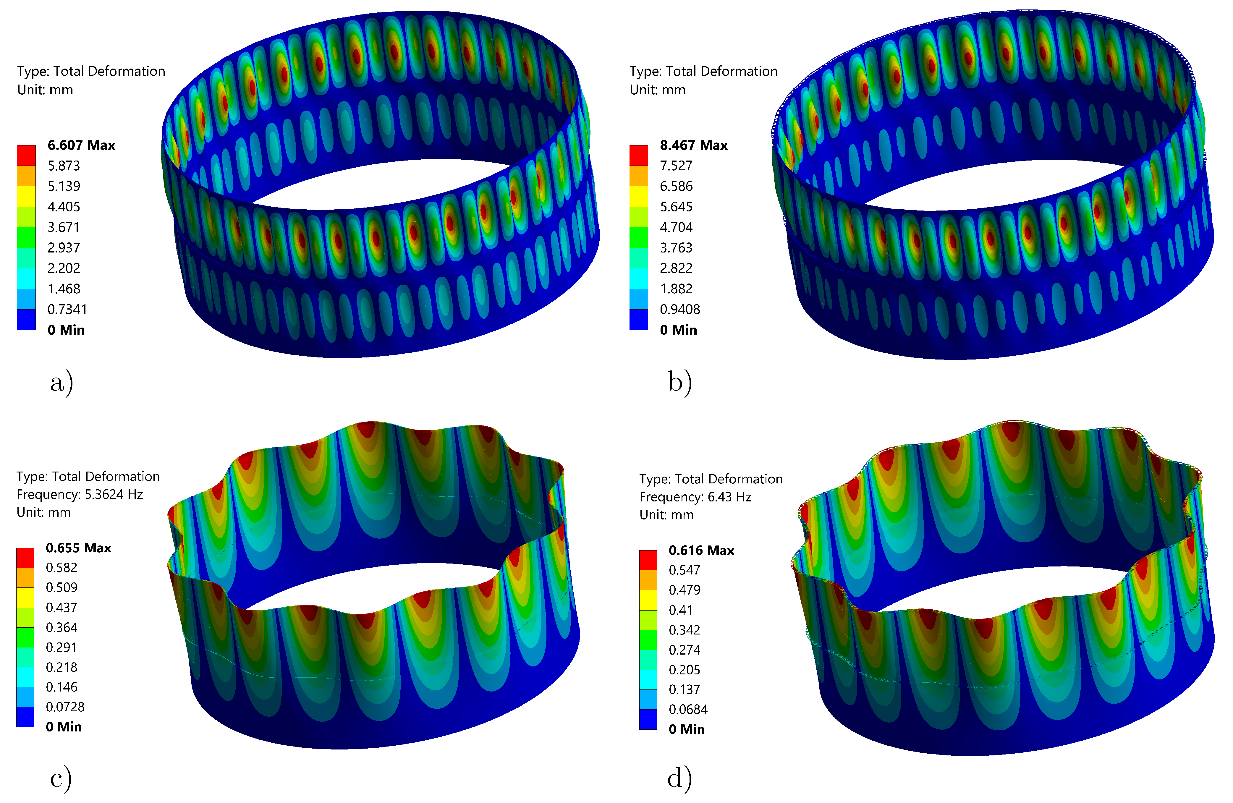
Table 6. The biggest relative deviation of critical pressure is in TK4, but the first natural frequency differs the most in TK6. For the variant TK5, the first mode shape from MA and the shape under critical pressure are shown in
Figure 11.
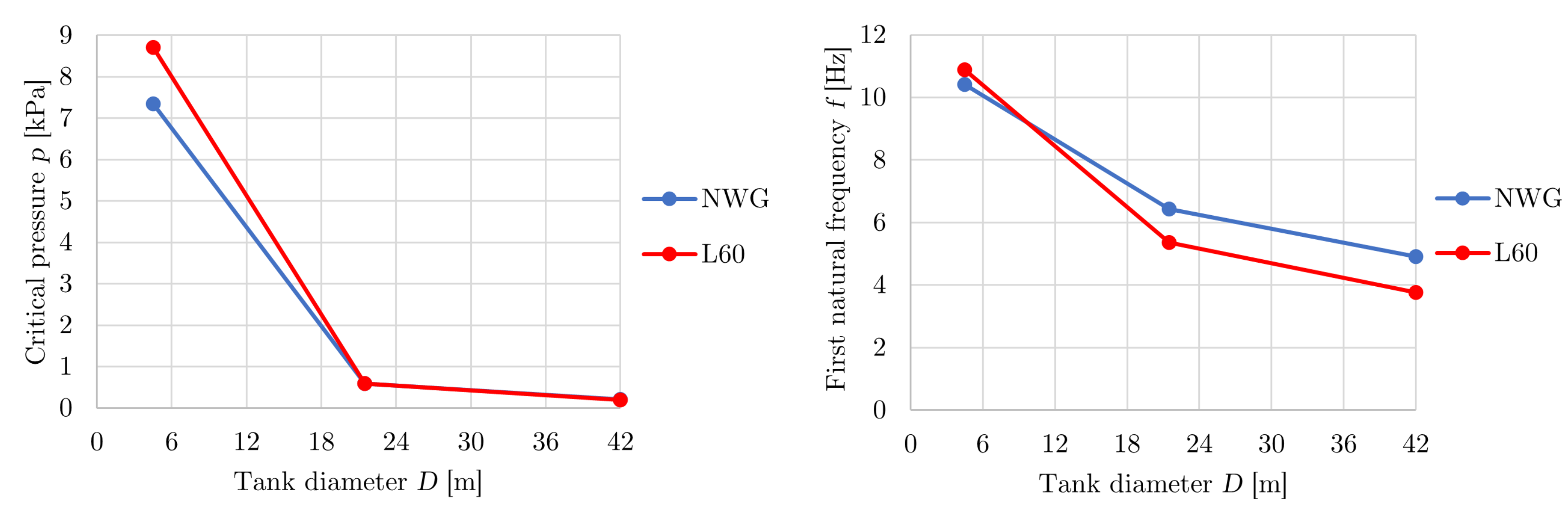
Figure 12 presents critical pressure and the first natural frequency of the models with both types of girders. As with the low-height tanks, there is an obvious trend that as the diameter of the tank increases, both evaluated values decrease.
3.3. Application of New Wind Girders to High Tanks
The results for the high tanks
m (TK7, TK8, and TK9) are similar to those for the middle-height tanks. The shapes from the individual analyses are comparable but critical pressure values, maximum displacements, and natural frequencies vary. As can be observed from
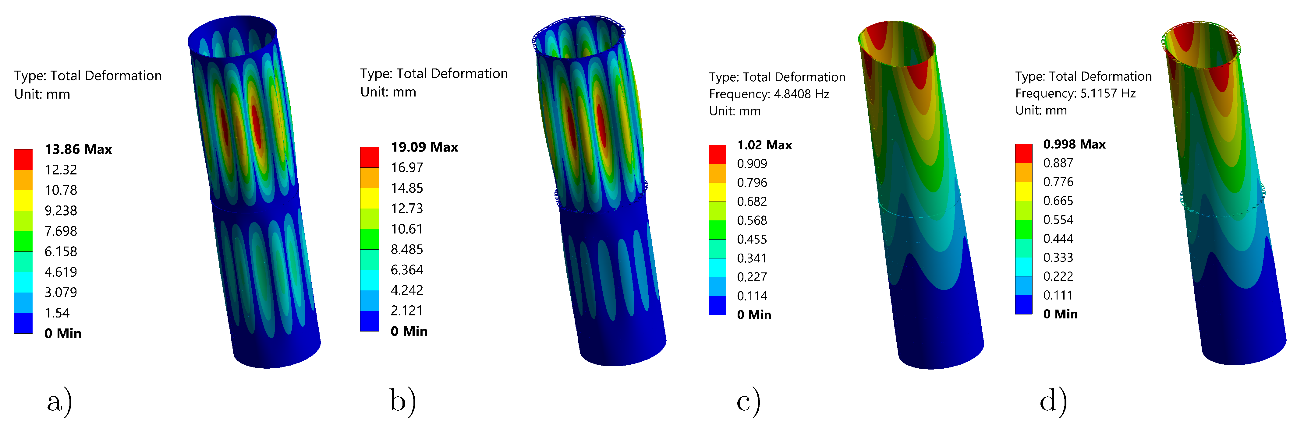
Figure 13, the first natural frequency is higher for a model with NWG for all three variants in this evaluated set. However, the critical pressure varies for each variant and the biggest difference is again for a variant with a small diameter (TK7). The mode shapes and shapes under critical pressure for variant TK7 are shown in
Figure 14 and the corresponding values are listed in
Table 7. For this variant, maximum displacement is higher for a model with NWG, although the shapes are similar.
3.4. Comparison of Results Obtained from LBA and GMNIA with Analytical Models
In this section, the comparison of results from LBA and GMNIA with analytical models is presented. Because LBA is not suitable for thin shell structures, this paper focused on GMNIA, which is more precise. But to compare the results obtained from GMNIA, the above-mentioned methods were also used. Critical pressure from LBA was obtained as eigenvalue, which was multiplied by the defined initial load. Values are listed in
Table 8, where
is critical pressure for the model with L60 and
is critical pressure for the model with NWG. Critical pressure from analytical models
and
were determined based on standards described in
Section 2.3. However, the different types of girders have not been taken into account in these analytical models. In the last two columns in
Table 8 is the ratio between GMNIA and LBA for both numerical models. As one can observe, the critical pressures obtained from GMNIA were lower for all variants. When comparing the analytical solution and LBA, one can see that the critical pressure is significantly lower for both methods. An interesting comparison is between the analytical solution and GMNIA. The critical pressure values according to EN ISO 28765 (
) were very close to the numerical results for both types of girders for most variants. In some cases, the critical pressure was even higher, so the standard gives less conservative results. The second analytical approach (EN 1993-1-6) is rather more conservative, which may be due to a more detailed implementation of imperfections.
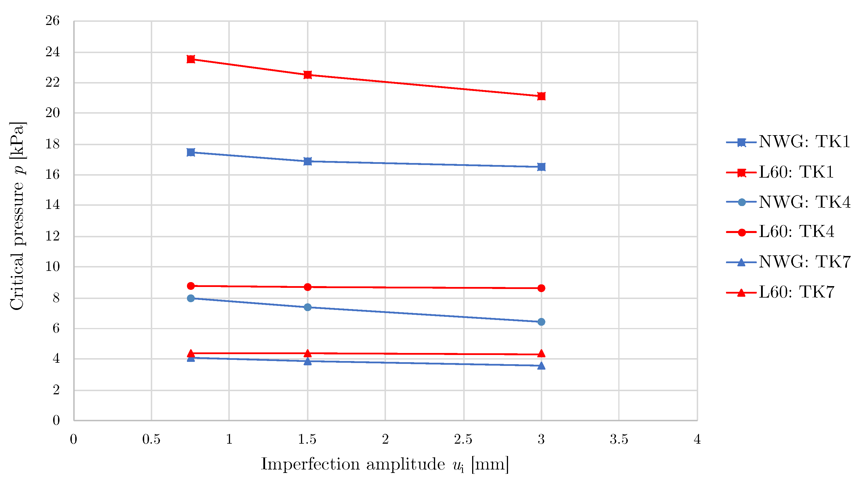
3.5. Geometrical Imperfection Study
In this section, results of the influence of imperfection sizes are presented for three variants (TK1, TK4, and TK7), which differed greatly from the L60 model. These variants include a sample from the low-height, middle-height, and high tanks. The magnitudes of the imperfection amplitudes were selected based on the thickness of the tank wall. Three sizes of amplitudes were considered 0.25
, 0.5
, and 1
and calculated critical pressures are listed in
Table 9. The dependence of the critical pressure on the imperfection amplitude is plotted in
Figure 15 for both models.
As can be observed from
Table 9, increasing the imperfection amplitude decreases the value of critical pressure. The maximum deviation from the imperfection amplitude used in this paper (0.5
) was about 12%.
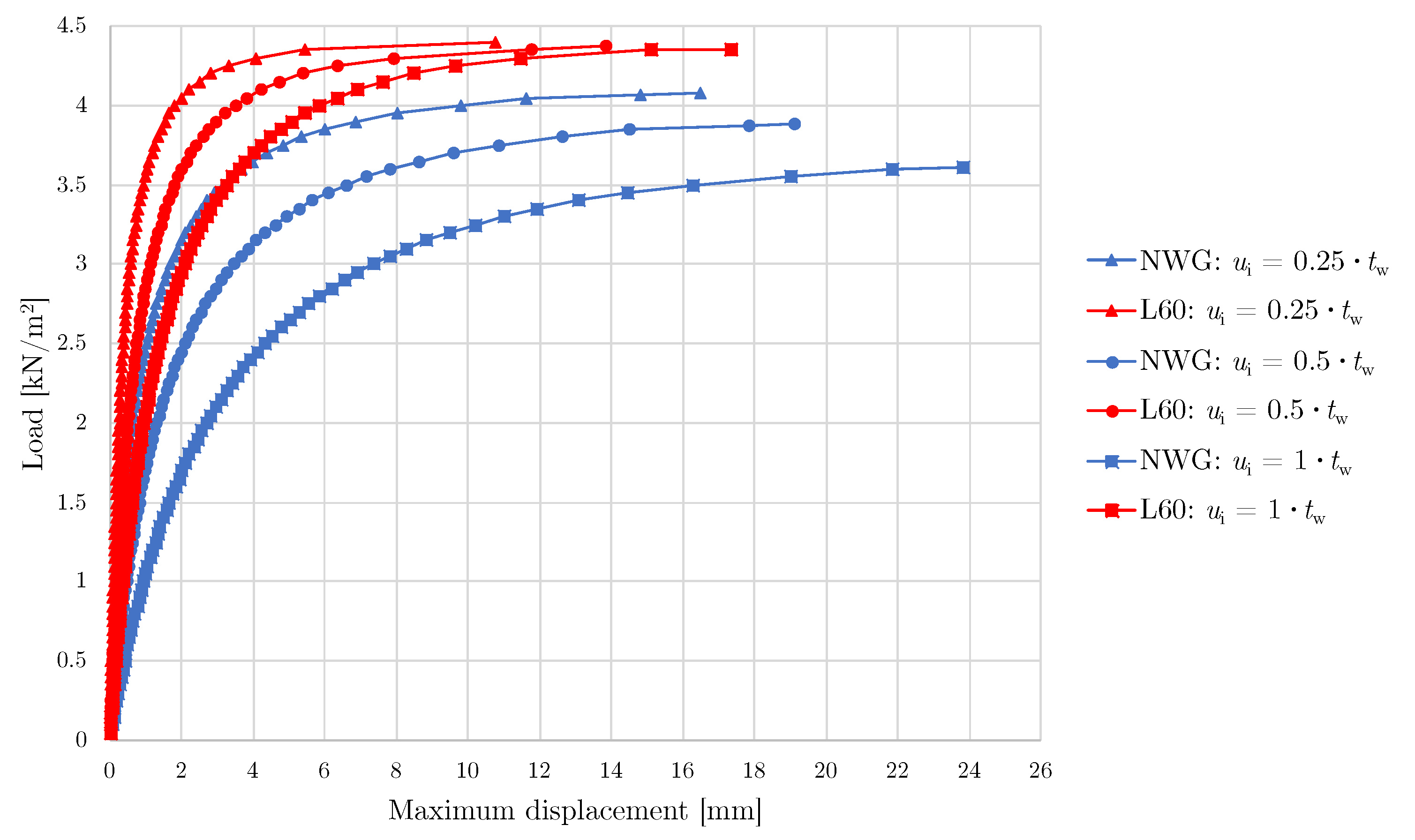
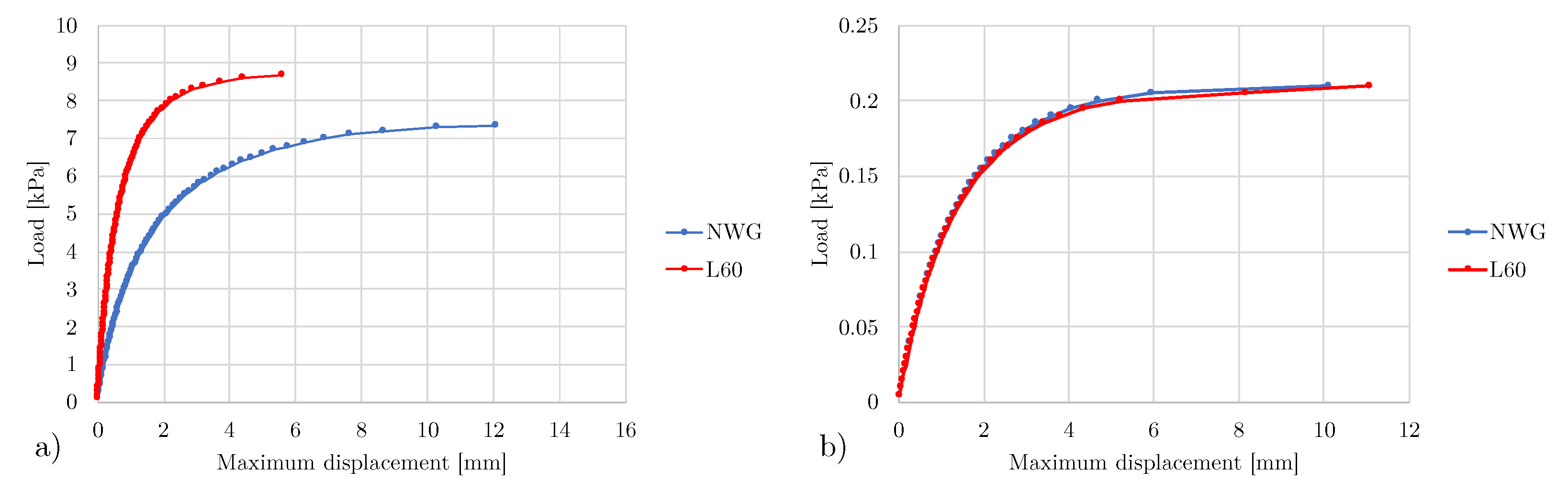
Figure 16 shows load–deflection curves for variant TK7 for the L60 model and the NWG model. It can be seen from the results that the NWG model is more sensitive to the size of imperfections.
3.6. Evaluation of NWG Results
For some variants (TK3, TK5, TK6, and TK9), buckling capacity is higher for models with NWG. The smallest difference is for variant TK5, where the relative deviation is only 1.5%. On the other hand, the biggest difference is in variant TK6, where the relative deviation is 2.5%. It means that for these variants, the difference in buckling capacity is negligible. An important observation is the higher buckling capacity of a model with L60 for the rest of the variants (TK1, TK2, TK4, TK7, and TK8). The biggest deviations are in variants with small diameters (TK1, TK4, and TK7), specifically 25.1% for variant TK1. The critical pressure values are closest to each other for TK8 with a relative deviation of 7.6%. For these variants, it would be possible to increase the thickness of NWG segments from which the girder is made to increase buckling capacity. The obtained results show the variable behavior of the girders for different tank variants.
Maximum equivalent stresses in tank walls were comparable for both models for most of the variants, except small-diameter tanks (TK1 and TK4). In girders, the stress results were quite different. These differences were probably most affected by the influence of the variable stiffness of NWG and stress concentration. It means that NWG is formed by segments, and in certain places, the thickness is only 4 mm. However, in all variants, the maximum equivalent stress (HMH) did not exceed the yield stress when the load reached the evaluated critical value. So, evaluated failures were due to large deflection or zero tangent stiffness.
Load–deflection curves for two middle-height variants (TK4 and TK6) are plotted in
Figure 17. One can observe that for variant, TK6 load–deflection curves were very comparable. It also corresponds to the value of critical pressures, which were almost equal. On the other hand, for variant TK4, it is evident that the curves for the L60 model are above the NWG model. Displacements were smaller at higher levels of load, and critical pressure was larger. So, in this case, the L60 model seems to be more rigid.
Also important are the results of MA, in which the values of the first natural frequency differ significantly. Especially for TK1, where the value of the first natural frequency is considerably lower for the model with NWG. The relative deviation is 28.3%, the absolute deviation is 11.1 Hz and the first mode shape also differs markedly, which is a significant difference for this type of construction. This may be due to insufficient stiffness of NWG in the upper part. If the first natural frequency had to be increased to achieve the same mode shape as the model with L60, the tank wall had to be additionally reinforced or different dimensions of NWG had to be used. On the other hand, the biggest difference is for TK9, where the first natural frequency is almost 50% higher for the NWG model. However, first mode shapes do not differ much in this case. For the remaining variants, mode shapes are already comparable to each other, and only first natural frequencies differ.
Figure 10,
Figure 12 and
Figure 13 show the trend of the studied variables depending on the tank diameter for both types of girders. From the figures, it can be seen that the natural frequencies of the model with NWG come out worse for low tanks. It is also noticeable that as the tank diameter increases, NWG performs better compared with L60. This reflects the better behavior for the given design of NWG for large tanks (TK3, TK6, and TK9). This makes the use of NWG easier to manufacture, especially for large-diameter tanks, where they represent a significant part of the total mass. On the other hand, L60 shows better behavior for tanks with a diameter of 4.3 m.
4. Discussion
Wind girders are mainly used to increase buckling capacity. The new design of a girder in the form of segments (
Figure 3a) can be used to replace the conventional girders (
Figure 3b). As the shape of the girder is designed, the basic geometrical parameters given in
Table 2 can be modified to achieve higher stiffness of the girder and consequently increase the overall buckling capacity for individual tank applications. The main difference with commonly used girders is their changing stiffness in the circumferential direction, so the numerical model is needed for further evaluation. As the study is used to compare NWG with L60, the values of the loading pressure do not correspond to the specific location of the tank and the real wind distribution according to EN 1993-1-4 [
8]. For a concrete application, it would be advisable to implement this and assess the influence of these specific parameters for a given location.
The presented analyses are focused on the non-linear buckling analysis of empty tanks. To assess the stress–strain behavior, it would be possible to design a more precise model and evaluate the stresses and strains in the girders and the tank wall. Only tanks without roofs are included in the analyses, as there is a higher risk of buckling due to negative pressures acting on the inner tank wall. In the case of tanks with a fixed roof, there is partial stiffening of the roof structure at the top edge, and as the tank is closed, no suction from wind occurs in the inner part of the tank. The effect of internal pressures is also considered in publications [
1,
25].
A study was carried out in the field of testing large-capacity tanks. Based on the obtained information, it is not possible to test the analyzed tanks even in the largest wind tunnels, e.g., in the “Jules Verne climatic wind tunnel” [
42] in France. Testing smaller tanks is possible but very expensive. In the case of testing scaled models, it is difficult to perform experiments that are valid for application to analyzed tanks. This is mainly due to the availability of very thin plates and small girders and bolt connections. For these reasons, the experiment of each model is not implemented in this paper. Simplified analytical models according to EN 1993-1-6 and EN ISO 28765 were used to compare with the numerical results (LBA and GMNIA).
In this paper, the seismic load is not considered, which also has a major influence on the tank configuration if the tank is located in the seismic area. Numerical evaluation of tanks excited by seismic loads was carried out by authors Spritzer and Guzey [
43]. To model the seismic load, it would be useful to design a more precise 3D model with the replacement of the fluid with finite elements and simulate the problem as a fluid–structure interaction (FSI) as presented in the publication of the authors Compagnoni and Curadelli [
44]. In this case, it would be appropriate to investigate both roofed and open-topped tanks and also determine the height of the sloshing wave during the earthquake and the forces acting on the foundation. For roofed tanks with an insufficient height of the water level from the top edge (so-called freeboard), the roof could be damaged due to the effect of the sloshing wave, which is described in more detail in References [
45,
46]. In terms of the assessment of NWG, the influence of the occurring hydrodynamic effects and the vibration of the tank on the behavior of the wind girders could be investigated.
These analyses are focused on bolted tanks (not welded), and for this reason, it is recommended to have a more precise model with substitution of the real bolts, e.g., by beam elements, and also evaluate the stress in the bolts and the tank wall due to the net section. In this way, it would be possible to design the ideal bolt spacing and size for each tank design under known loads. To perform a more detailed analysis, it is also advisable to consider a full shell model by replacing the single sheets with shells and implementing the contacts between the single segments making up the girder and also between the girder and tank wall. In this paper, simplification is applied and the nodes at the contacts between the girder and the tank are merged. However, for tank analyses, a combined model with shell and beam elements is often used, for example, by Zeybek et al. [
47], who dealt with the evaluation of stress resultants in the girders.
As the tank problem is a symmetrical thin-walled structure, it is not recommended to apply a linear buckling analysis. The resulting eigenvalues do not exactly predict the real global buckling and collapse of the tank. Therefore, the linear buckling analysis is preferably used as an input preliminary shape to the following more precise GMNIA, as is also recommended by Maraveas et al. [
19]. In this analysis, the imperfections that are present in real structures are already implemented. Similarly, imperfections are included in the analytical equations for a simplified assessment of buckling, given in EN 1993-1-6 [
11]. A sensitivity analysis of the imperfections can be performed, and the size of the imperfections modified. The imperfection amplitude can affect buckling capacity, which is also seen in the publication of the authors Chiang and Guzey [
20].
The parametric study is performed for tank variants with uniform wall thickness
= 3 mm. This is not very common in industrial applications, especially for larger tanks. The resulting values of the critical pressure are only used for a clearer comparison of the different types of girders and to realize a parametric study, so the thickness variation in each row is not considered. Three different tank diameters and three heights for each diameter are selected. The values in
Figure 10,
Figure 12, and
Figure 13 show the non-linear trends. To smooth the curves, more values in the diameter interval
D = 4.3–42 m should be used. Furthermore, an axisymmetric pressure is applied as a load over the entire circumference and height of the tank, which is conservative to buckling. However, when designing tanks according to real local conditions, the non-uniform distribution of wind pressure according to EN 1994-1-4 [
8] is usually applied, where the effect of the negative pressure occurring in open-topped tanks should be included as well.
In
Table 10, the main advantages of both wind girders are summarized. Based on the obtained results, NWG has more benefits compared to conventional profiles. Except mass per length is larger for NWG compared to L60, it may not mean that the total price is also higher.
5. Conclusions
This paper has presented the design and numerical analysis of a new wind girder (NWG) and the subsequent comparison of the designed shape with the model using the smallest used round-edged equal leg steel angle bar EN 10056-1 - L60 × 60 × 6 - EN 10025-2-S235JR (L60). The geometric design is based on a research study and on tank dimensions taken from technical applications. After designing the basic dimensions of the girder listed in
Table 2, a parametric study of nine tank variants is carried out to compare buckling capacity and modal properties of tanks with conventional profile L60.
The shape of NWG (
Figure 3a) is composed of segments with a rectangular cross-section that are bolted to the tank wall and to each other. This shape with a rectangular cross-section is easy to produce and also can be easily bent to the required curvature compared to the commonly used profiles. The designed girder can be quickly modified while retaining the geometry concept by only changing the thickness of the used plates. This increases their moment of inertia and thus buckling capacity of the whole tank. As listed in
Table 11, the total mass of NWG is slightly higher than L60. However, due to the simpler cross-section of NWG, the production costs are lower. The main disadvantage of the new shape compared to the conventional girders is the variable moment of inertia around the circumference of the tank. This causes a different behavior, and it is not easy to design the dimensions of the girders using analytic approaches based on the comparison of the moment of inertia or the section modulus. The mentioned standards specify a minimum moment of inertia (or section modulus) for the upper and intermediate girders; therefore, the design of NWG should be verified by the non-linear numerical model. Based on the obtained results, NWG can replace L60; however, a more detailed numerical analysis is required for tank design to verify the application.
A non-linear analysis with imperfections (GMNIA) was used to compare the buckling capacity of girders. The imperfections were taken from the linear bifurcation analysis (LBA). The girders were analyzed on several tank variants of different diameters and heights. The results show that the designed shape of the wind girder can be used instead of the conventional girders. As the results obtained for the analyzed variants are relatively varied, it is advisable to assess the specific tank configuration with a given load using numerical analysis. For some variants, the new design gives a better result, while in other cases, the currently used girders appear to be better. According to the achieved results for the given configuration and chosen variants, NWG seems to be better for tanks with larger diameters. This may be due to the fact that for tanks with larger diameters more segments are used, whereas for small-diameter tanks, the number of segments is insufficient. Different punching and segment geometries could be used to achieve a larger number of V-segments in these cases. It is evident from the modal analysis that, mainly in the cases of low tanks, the first natural frequency for the tanks with the new girder design is lower than for the conventional profiles. In one variant (TK1), the first mode shape was also different and indicates that, in some cases, the tank is not adequately stiffened and a more rigid profile should be used. The lower first natural frequency may also have an influence on the formation of the resonance under wind or seismic action. Conclusions can be summarized in the following terms.
The cross-section of NWG segments is very simple and can be easily produced by common manufacturers.
Although the total mass of NWG is slightly higher than for L60, due to the obtained results, NWG could be compared with the larger cross-section profiles usually used for tanks with larger diameters and possibly replace them.
Although the total mass of NWG is slightly higher than for L60, the total price should be less because of the simpler cross-section and therefore lower material prices.
The geometry is designed so that NWG can be used for different tank curvatures and stiffness requirements. By modifying the basic dimensions of segments, the stiffness is increased and overall buckling capacity is also increased.
Because NWG is composed of simple segments with various curvatures, it is convenient for storage and assembly.
An important difference of NWG compared to conventional girders is the variable moment of inertia around the circumference of the tank, which requires a more detailed assessment using GMNIA.

 ,
, 


