1. Introduction
In Europe, Italy represents one of the most seismically active countries. On the 20th and 29th May 2012, Northern Italy was struck by two earthquakes, which hit the territory of Modena, Ferrara and Bologna in the Emilia-Romagna region, as well as Rovigo and Mantua in the Veneto region and Lombardia, respectively [
1]. The moment magnitude M
w of the first seismic event, having an epicentre in Finale Emilia, was 5.9, whereas that of the second one, with an epicentre between Mirandola and San Felice sul Panaro, was 5.8. The peak ground accelerations (PGA) measured by the Italian National Accelerometric Network (NAN) station located near Mirandola, a city close to the epicentre of the first seism, were reported to be about 0.31 and 0.29 g for the 20th and 29th May earthquakes, respectively [
1].
There were 28 deaths (17 victims during working time), 390 injured and 19,000 evacuated people. Even if the Northern Italy earthquakes were among the less hazardous seismic events that have occurred in Italy in the last fifty years in terms of deaths, these events had a strong repercussion on the economy of the Emilia-Romagna region [
2]. In fact, several industrial warehouses collapsed due to the seismic sequence [
3,
4]. This was due to the construction typology of these artworks, usually vulnerable to earthquakes, as well as to both the recent seismic classification of the area and the earthquake type inducing strong accelerations in tall storerooms [
5].
Since racking collapse can be very dangerous for both workers and stored goods, it is fundamental to boost earthquake preparedness for the warehouse industry, especially in high-intensity seismic regions, such as Italy [
6]. While global collapses and high numbers of victims affect structures of different construction technologies, the damage could be drastically reduced by using steel structures [
7].
In the Emilia-Romagna territory, as for other seismic events, the steel structures responded adequately to the induced ground shaking. Considering that Italy entered the whole seismic classification in 2003, all the buildings erected before that year were practically designed in agreement with an obsolete standard based on wind-induced forces as the only horizontal actions. Consequently, numerous constructions collapsed under earthquake actions. As an example, several precast RC sheds underwent seismic failures due to many reasons, which were mainly due to poor connections among structural elements and lack of structural redundancy. Contrarily, the last earthquakes demonstrated a more satisfactory behaviour of steel constructions, highlighting an intrinsic capacity of the metal structures to fight well against earthquakes. This was due to the main features of these structures that, other than the good characteristics of the basic material in terms of strength, stiffness and ductility, are provided with rightly conceived connections and possess appropriate structural robustness [
7,
8]. In addition, while RC precast industrial buildings are heavy structures for which seismic actions are significantly larger than wind ones, steel ones are light structures where earthquake and wind actions are usually comparable to each other. The result was that steel structures designed toward wind forces also behaved well under seismic actions.
On the other hand, with reference to precast RC warehouses, the most frequent causes of partial and global collapses are [
9,
10]:
- (a)
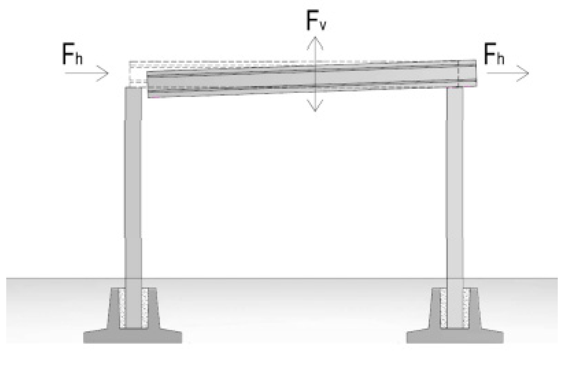
Loss of support and damage of connections among structural elements (
Figure 1). The greatest number of cases fell because of the failure of connections (beam-to-column and tile-to-beam). In fact, for these structures, columns simply support beams so that the transfer of the horizontal action is delegated to purely friction joints.
- (b)
Collapse of infill panels (
Figure 2). The boundary walls of these buildings are made of bricks in recent constructions and of precast RC panels, arranged horizontally or vertically, for buildings of more recent conception. In the former case, the infill walls either reported serious cracks due to in-plane forces or showed overturning mechanisms due to the failure of infill-structure connections. In the latter case, hammering between the rigid boundary walls and the main structure resulted in much greater deformation of the main structural members. Furthermore, the loss of anchoring due to the differential displacements of the main structural elements eventually contributed to the system’s instability.
- (c)
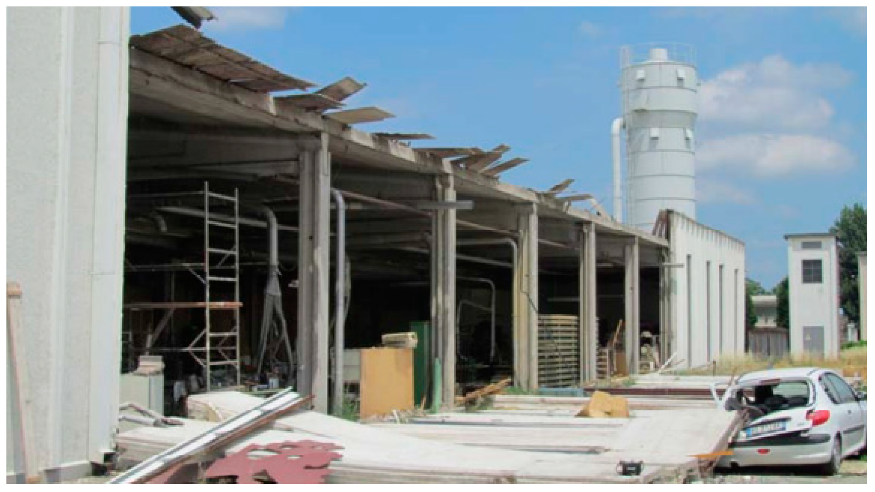
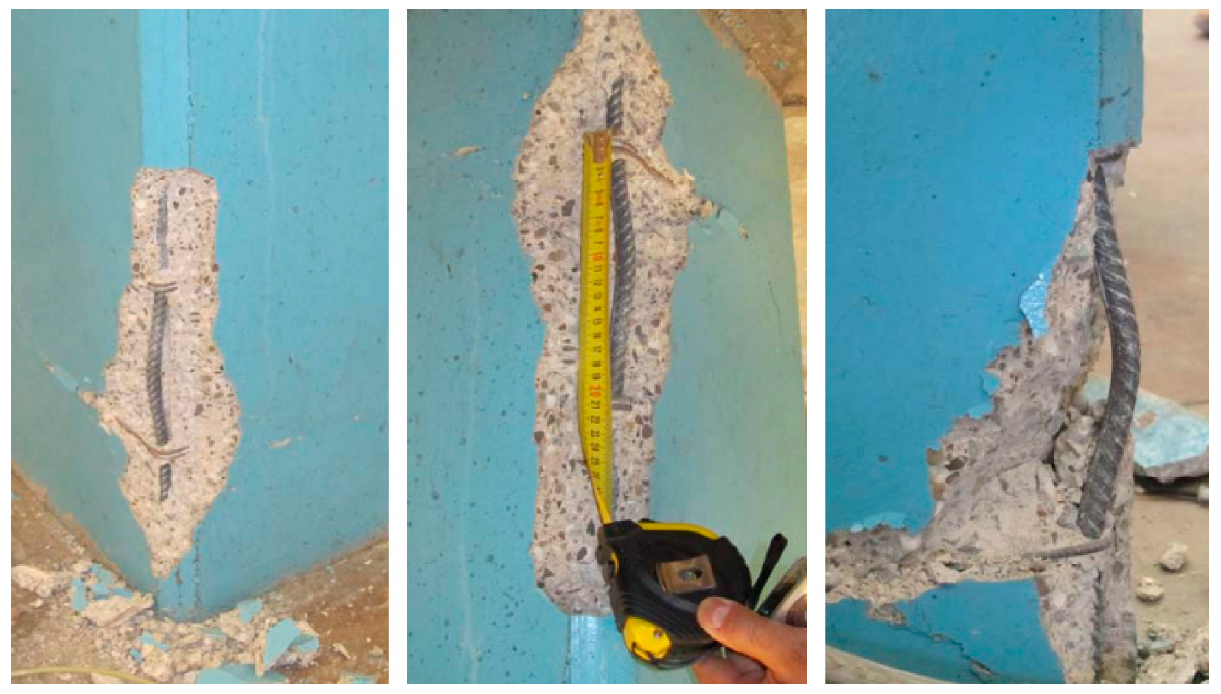
Damages to the columns (
Figure 3). In the area of interest, the damages of vertical members were ascribable to the loss of verticality, which was either caused by the rotation of the entire foundation system or produced by the formation of a plastic hinge at the base with consequent cracking. Several damages to the columns were also caused via impact with collapsed beams or tiles.
- (d)
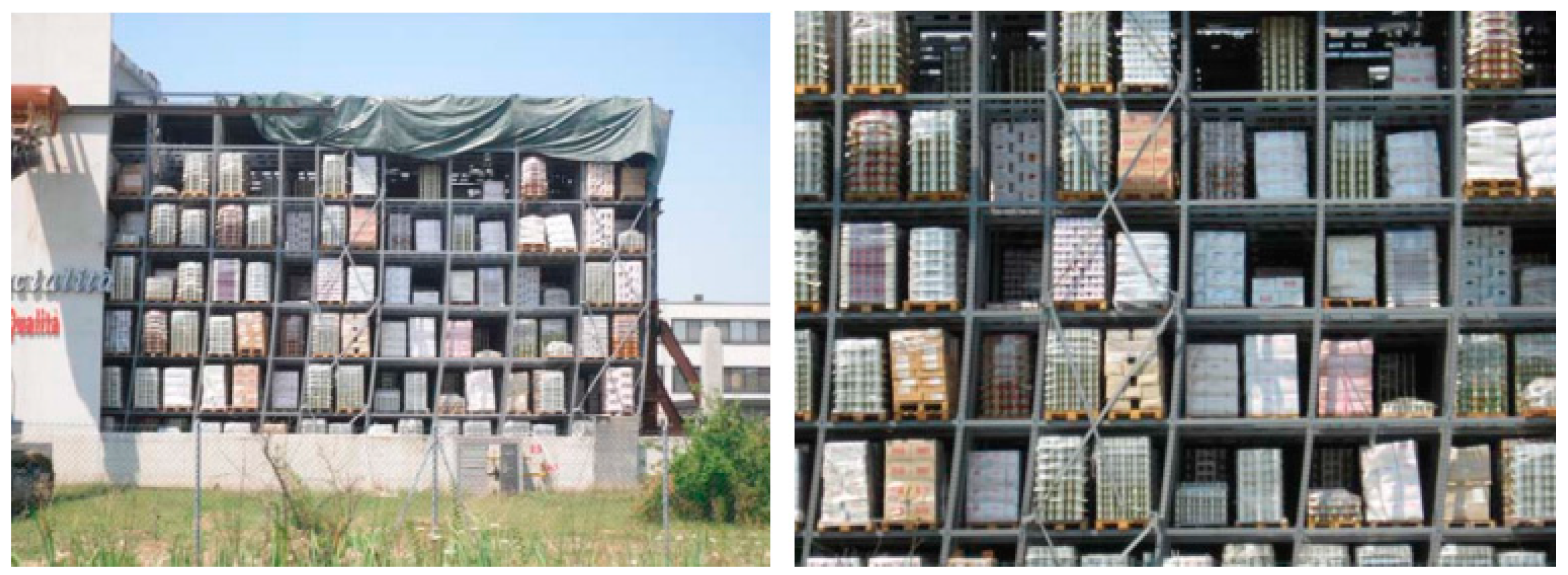
Damages and collapse of indoor shelves (
Figure 4). This classification includes all shelving units available either for goods storage or open to the public. These are metal constructions made of thin cold-formed steel profiles, continuously drilled and connected with bolts or hook devices. As an example, with reference to the Emilia-Romagna earthquake, such structures, generally having a height of 10 to 12 m, were mainly used to store Parmesan cheeses. This earthquake highlighted the limits of this type of shelving, usually designed only to resist gravity actions, which were incapable of sustaining seismic forces.
In this situation, it is important to analyse studies about seismic assessment and the retrofit of existing buildings, which were usually performed through non-linear static and fragility analyses [
11,
12]. A wide investigation aimed at inspecting the different technologies used for seismic upgrading or the retrofit of structures was carried out in [
13]. In this paper, about 20,000 projects were examined to evaluate the technical solutions, and the related financial contributions requested to recover the damaged buildings in the aftermath of the earthquake. Even if this study referred to the earthquake that struck Central Italy in 2009, it is useful to observe how the choice of steel-based technologies was not common among designers. After this earthquake, the different technologies used for seismic upgrading projects of damaged buildings, which should attain a seismic safety index of at least 60% to receive financial support, were intensively summarized in [
8]. From this study, it was noticed that, among the various technologies, Carbon Fibre Reinforced Polymers (C-FRP) represented the most used solution, which was always present in mixed interventions. In fact, the designers considered the carbon fibres more reliable and economically convenient, as shown by the calculations attached to the projects. Nonetheless, as observed in [
14], this trend was in contrast with the effectiveness and cheapness of steelwork interventions, which were widely used in the past for repairing and reinforcing existing structures. For this reason, in the current paper, the use of steelwork under the form of local interventions was applied to a case study of a precast RC warehouse, which was analysed to show the reliability, both locally and globally, of steel to improve the inspected building.
2. The Case Study
The need to protect industrial buildings against earthquakes has guided the choice of a warehouse in Ferrara, a municipality hit by the 2012 earthquake, as a case study for many structures in the Emilia-Romagna region of Italy.
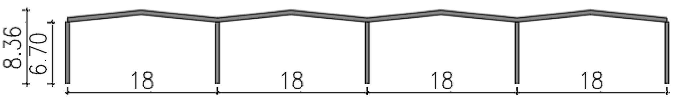
Erected at the end of the 1980s, the structure occupies a surface of 120 × 72 m with an internal height of 6.70 m, and it is covered by a pitched roof. The law in force at the time of the building erection was in contrast with the actual standard prescriptions, especially in terms of the design of connections. In fact, in the examined building, simple supports based on friction only are used as both roof tiles–beams and beams–columns constraints. Only with the Ministerial Decree for Public Works promulgated in Italy on 3rd December 1987 [
15] the use of purely frictional connections was neglected for structures in seismic areas. Nevertheless, when the building was built, this prescription was not considered since the Emilia-Romagna region was not considered a seismic zone.
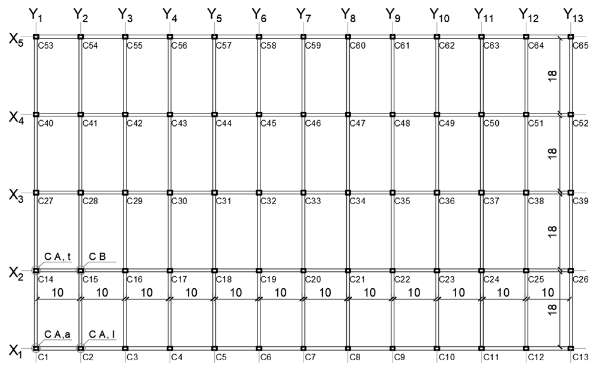
For what concerns the building materials, foundations and vertical structures were made of precast reinforced concrete, while prestressed RC was used for beams and roof tiles. The characteristics of the building and the structural elements are deduced from the original project of the building. The frames along the
Y-direction have been named from Y1 up to Y13, while the ones in the
X-direction have been indicated with the acronyms from X1 to X5 (
Figure 5). Sections of the building in the
X-direction and
Y-direction are depicted in
Figure 6 and
Figure 7, respectively.
In the transverse direction, the warehouse has four naves, while in the longitudinal one, there are 12 bays. The cross-section of all of the precast columns is 54 × 44 cm, whose reinforcement, dictated by a vertical load-based design, is different depending on the position of elements (perimeter columns, named type-A, with As = 12.56 cm2 and the reinforcement-to-section ratio of 0.5% and central columns, named type-B, with As = 25.12 cm2 and the reinforcement-to-section ratio of 1%), which are all oriented with the strong axis in the same direction. Precast RC double-tapered beams having a variable cross-section (75 cm at supports and 165 at mid-span) and with a span of 10 m are used as roof members. Perimeter and central beams have L-shaped and T-shaped cross-sections, respectively, in the longitudinal direction. Double T prestressed RC beams are roof elements sustained by the main beams through friction only. All precast elements are stretched using harmonic steel wires (15 ½-inch wires for variable cross-sections beams, 17 ⅜-inch wires for perimeter beams and 29 ⅜-inch wires for inverted-T-shaped beams) having conventional yielding stress and ultimate stress of 1350 and 1900 MPa, respectively.
3. Structural Modelling
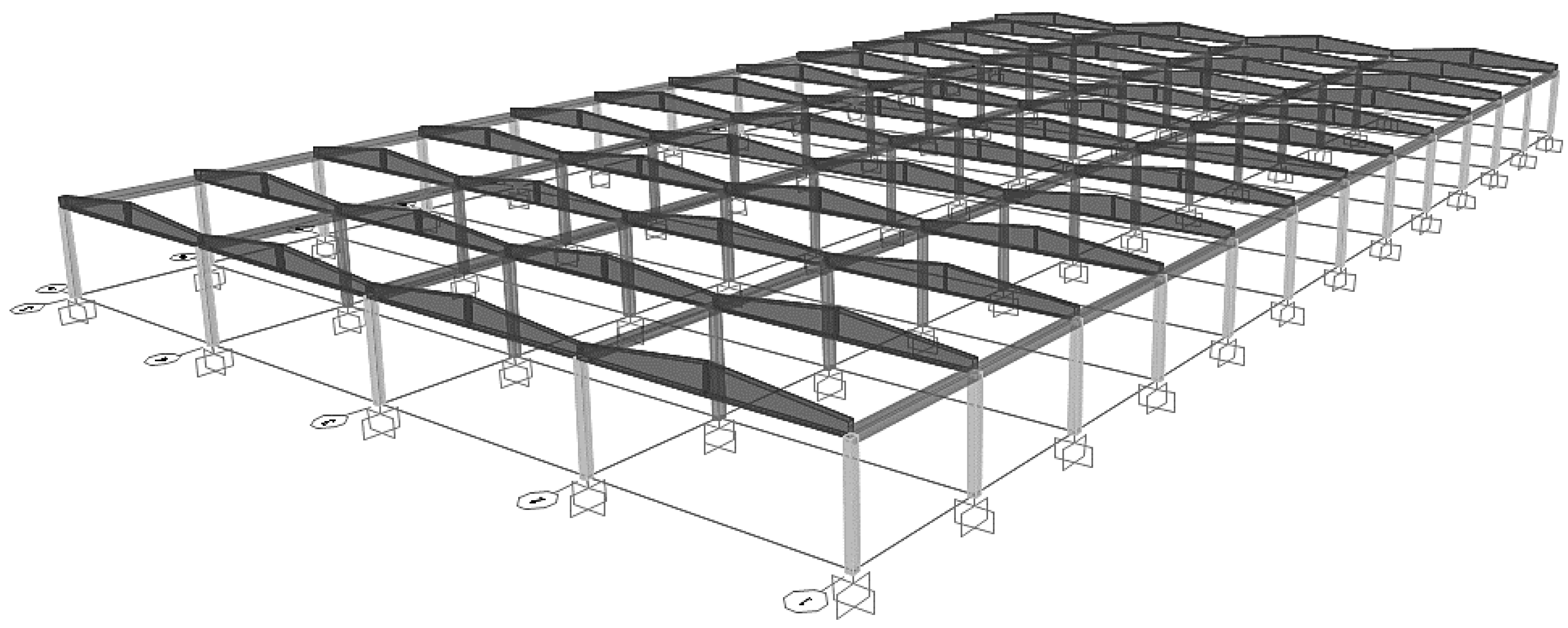
The structure has been modelled with linear elements using the software SAP2000 v.20 (Computer and Structures, Inc., Berkeley, CA, USA) [
16] (
Figure 8). From a seismic point of view, the improvement of the connection degree among elements assumes primary relevance. Therefore, starting from the actual static scheme of the warehouse with columns fully restrained at the base and beams simply supported by the columns, different types of connections have been investigated to evaluate a possible improvement of the structural response to seismic actions.
Hinge, semi-rigid and rigid joints have been considered as possible alternatives to connect beams to columns. Further, the assumption of an infinitely rigid roof has been assumed as the fourth (ideal) condition to evaluate the influence of a stiff floor on the building behaviour. The different connection types have been modelled by changing the internal constraint of beam-to-column joints (0 for hinges, 0.5 for semi-rigid joints, 1 for rigid joints and the “diaphragm” command for an infinitely rigid roof) to reproduce their different rotation capability.
The non-linear behaviour of RC members was taken into account through a concentrated plasticity model. The cracking of the structural elements subjected to seismic actions has been considered following the indications provided by the American Society of Civil Engineers (ASCE) [
17]. The column bending stiffness was reduced by 30%, while the shear by 40%. For prestressed beams, only the shear strength was reduced by 40%. The mechanical properties of materials are taken from laboratory tests. In particular, 30 tests on concrete cylinders and 3 tests on steel rebars were carried out. Moreover, the placement of rebars and stirrups was checked for at least 50% of the structural elements. In
Table 1, where γ
c indicates the concrete safety factor, the values of compressive strengths considered in the structural verification of various RC elements are reported. The prestressed RC components are made of C40/50 concrete, while C35/45 concrete is used for precast RC components. The mild steel used for the longitudinal rebars corresponds to the FeB44K type, whose mechanical properties are reported in
Table 2, where γ
s indicates the steel safety factor. Considering the number of tests on materials and knowledge of the original executive construction drawings of the building, an accurate knowledge level (LC3), with a unitary confidence factor (CF), has been used according to the Italian technical code [
18,
19].
4. Linear Dynamic Analysis
The maximum stress and displacement values associated with each vibration mode have been first calculated with the linear dynamic analysis, using a behaviour factor q = 1.5 [
18]. From the calculation of the first three vibration modes of a structure, it has been found that, as expected, the periods tend to reduce as the connection rigidity increases, as shown in
Table 3, where the periods of the first three vibration modes, the percentage of period reduction with respect to the static hinge scheme and the participating mass (M
x in
X-direction and M
y in
Y-direction) are reported.
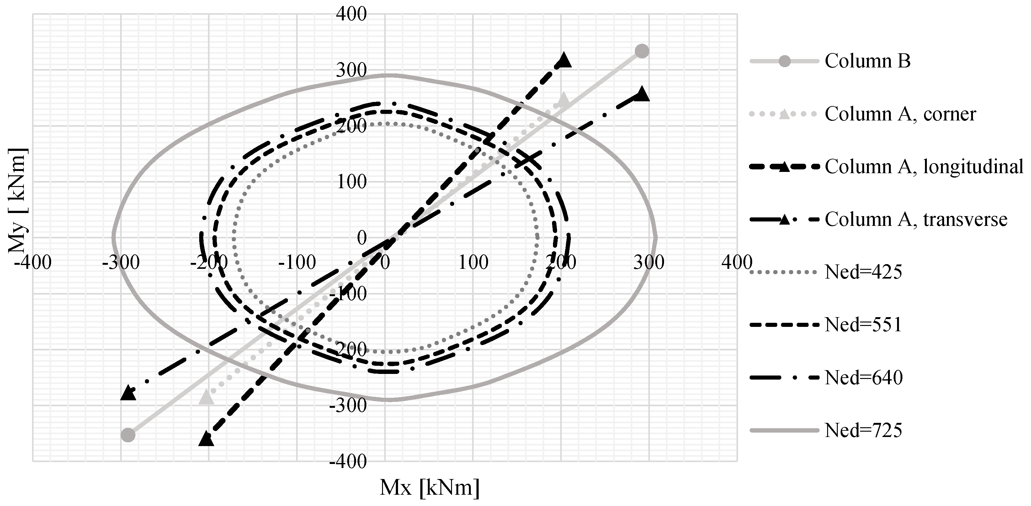
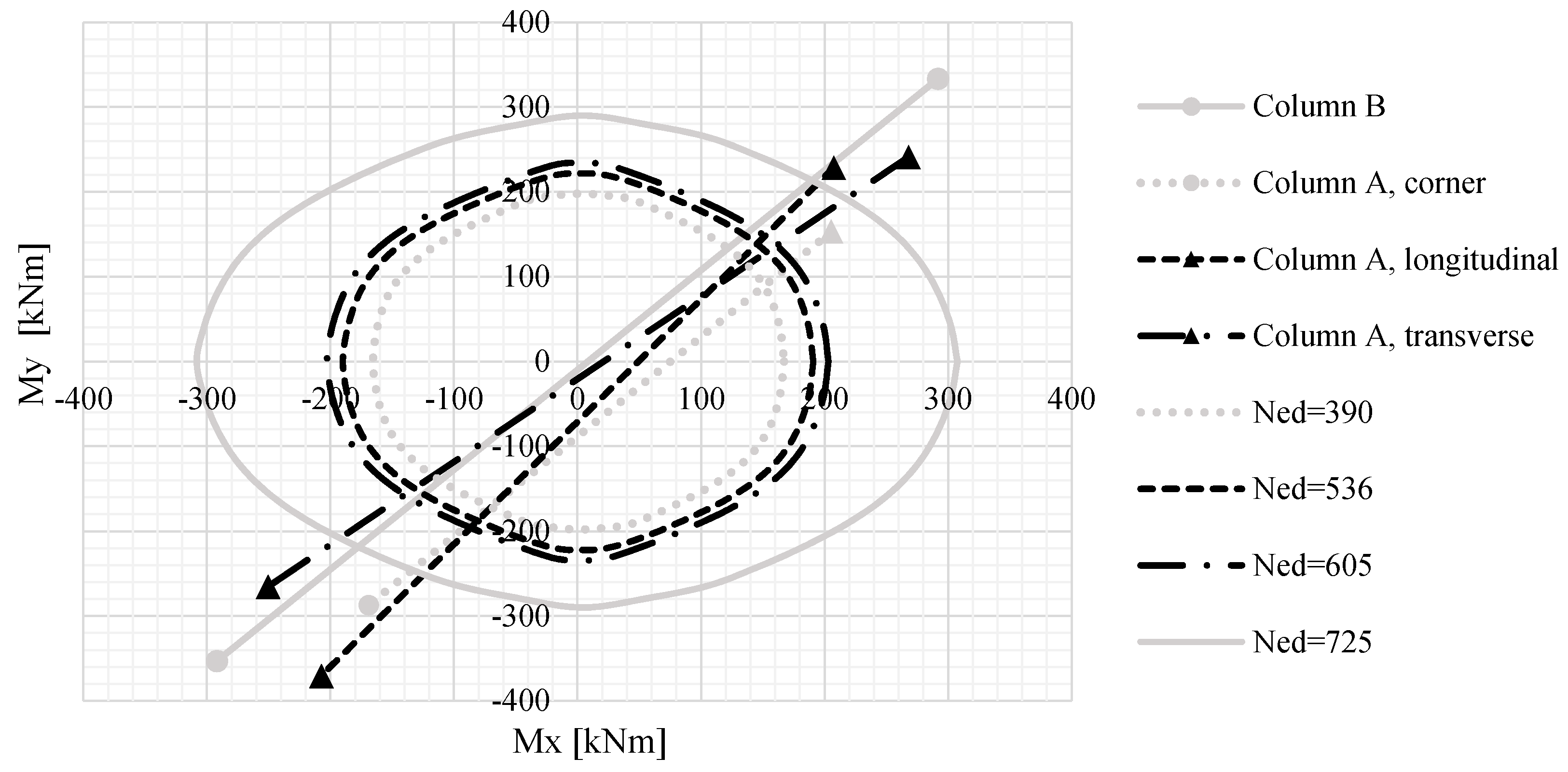
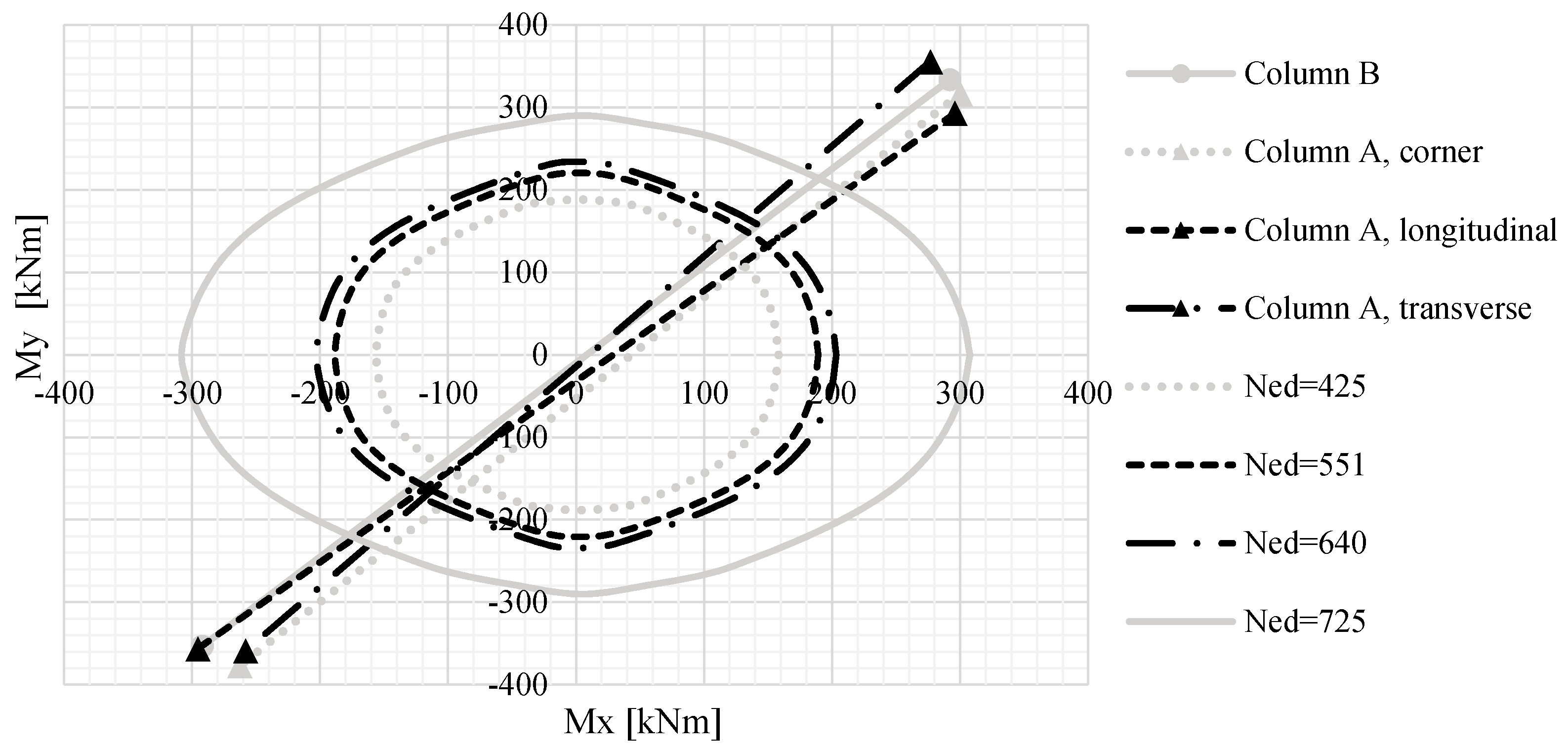
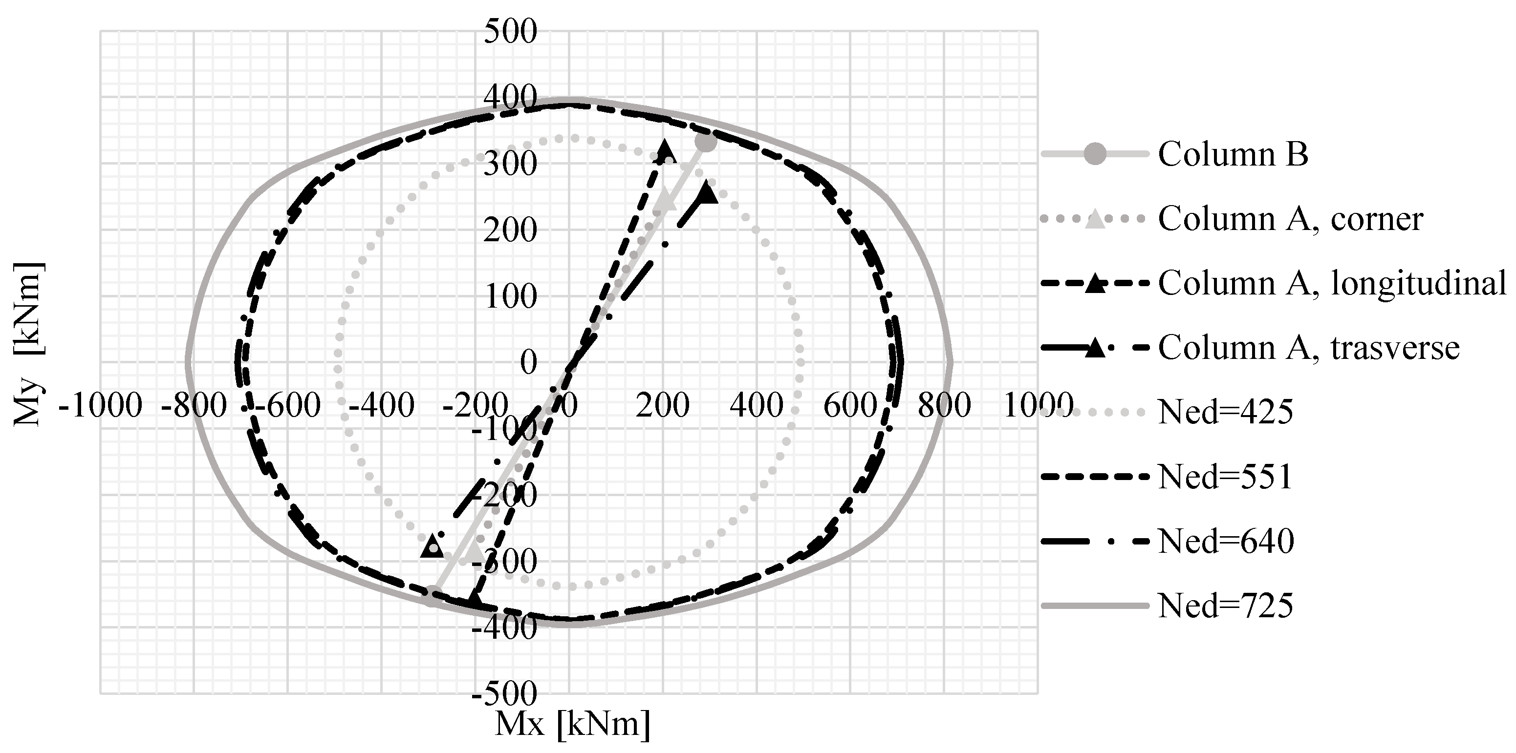
Since the seismic actions are applied in two orthogonal directions, the verification of columns in terms of bi-axial bending moment-axial force has been performed. Therefore, the software VCASLU v. 7.8 (Prof. Piero Gelfi, Brescia, Italy) [
20] has been used to plot the resistance domains M_(R
d,x)-M_(R
d,y) for the normal acting stress [
21]. As the axial stress N
Ed increases, the resistant moment raises and vice versa. Because the resistance domains are influenced by the intrinsic properties of the sections, as well as by reinforcement, both column types (type-A and type-B) have been examined. For type-A columns, a diagram of the variation of the normal stress has been plotted for corner (C A,a), longitudinal perimeter (C A,l) and transverse perimeter (C A,t) elements depicted in
Figure 5. Instead, considering the application of the same normal stress, a unique resistance domain has been built for a type-B column (named C B in
Figure 5). Resistance domains of all the building columns are shown in
Figure 9,
Figure 10,
Figure 11 and
Figure 12. For what concerns the beams, the verification against the bending moment is always fulfilled, as depicted in
Table 4.
5. Non-Linear Static Analysis
To learn more about the safety level of the existing warehouse and, therefore, to identify the post-elastic behaviour of structural elements, the response of the structure has been verified via a non-linear static analysis. This analysis highlights the performance of the structure regardless of the actual seismic demand. The plastic hinges have been assigned using a concentrated plasticity modelling approach according to the FEMA 356 prescriptions [
17]. They have been placed at the extremities of columns and beams in the models with semi-rigid joints, rigid joints and rigid roofs. Instead, with reference to the static scheme with hinges, the plastic hinges have been concentrated only at the base of the columns.
In the examined case study, the distribution of forces has been taken proportionally to the building masses due to the absence of an infinitely rigid diaphragm. Therefore, seismic forces have been laterally applied at the top of the different frames.
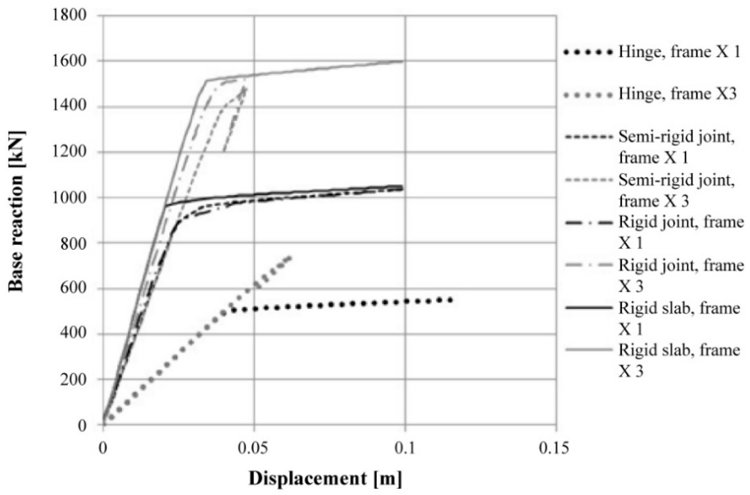
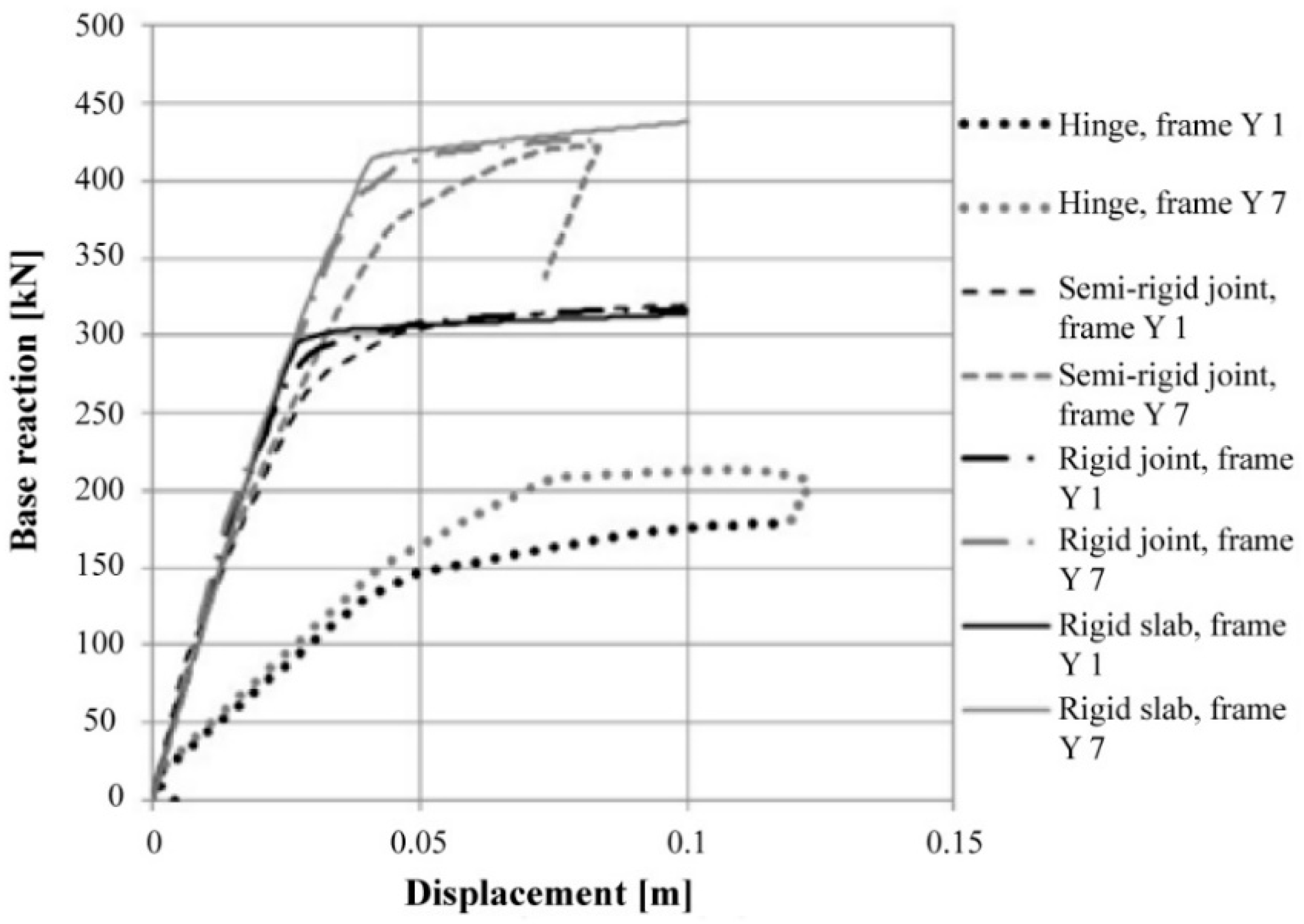
To better appreciate the seismic behaviour of the examined building with different connection types, the pushover curves of both intermediate and perimeter frames considered in the two analysis directions with the various beam-to-column joints and rigid slab assumptions have been reported altogether in
Figure 13 and
Figure 14, respectively. The curves showing an extremely accentuated plastic branch have been interrupted using the displacement limits provided by the FEMA 356 standard [
17]. Instead, the curves with a softening branch have been interrupted at a displacement corresponding to a reduction in the maximum resistance equal to 15% [
18]. From the pushover curves, it appears that central frames exhibit a base shear greater than that of end frames and that there is not a significant difference in terms of strength between the rigid joints scheme and rigid slab one. Moreover, for the central frame, the behaviour of three different static schemes (semi-rigid joints, rigid joints and rigid slab) is basically the same in terms of ductility.
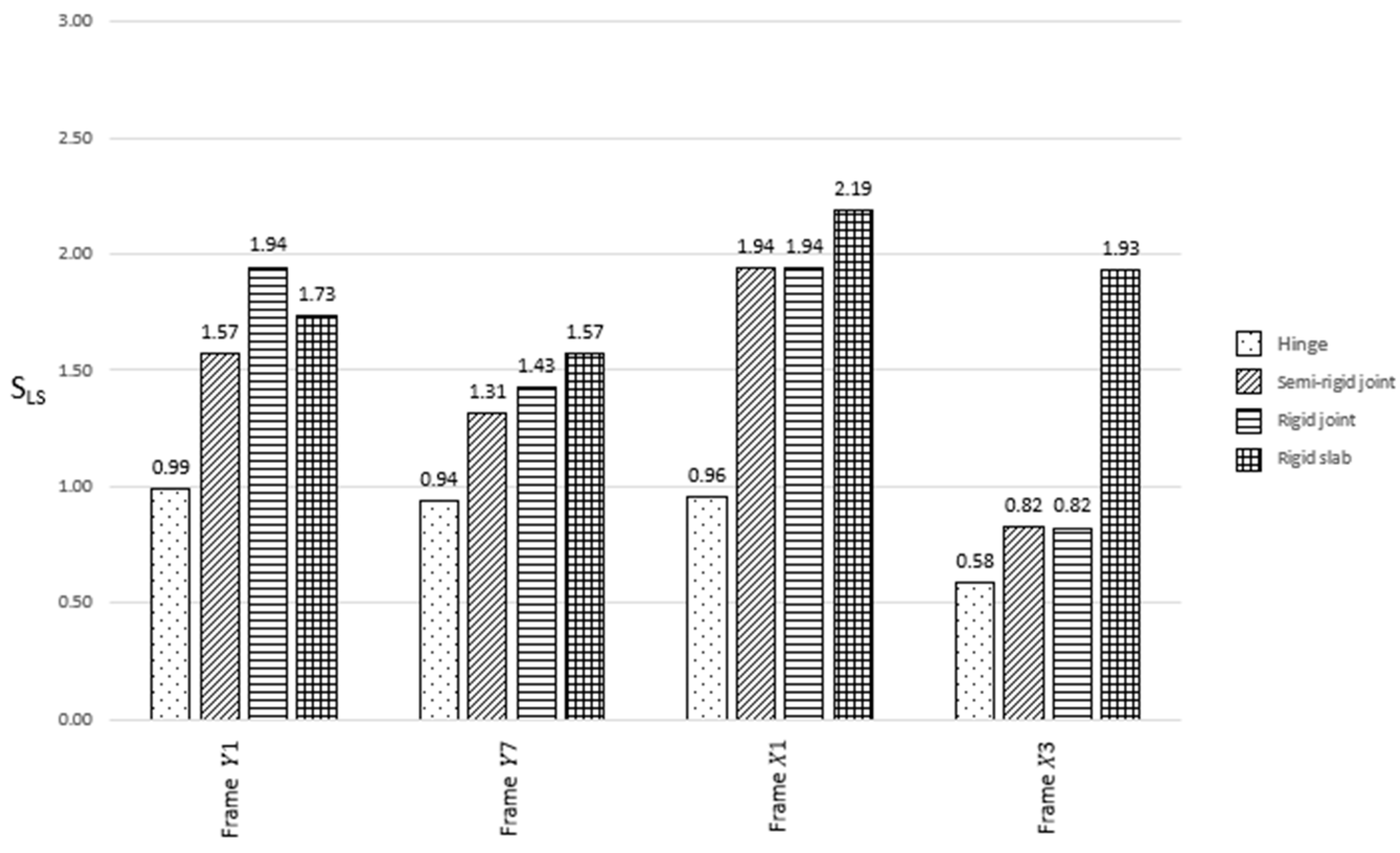
The capacity curves are based on the rigidity of the structures, which, in turn, essentially depends on their geometrical and mechanical characteristics. Due to the used distribution of forces, the N2 method cannot be applied to the whole structure. For this reason, the structure is broken up into frames considered SDOF systems. Since the frames have the same participating mass, the modal participation coefficient can be assumed to be equal to 1. The capacity curves are plotted in the ADRS plane, thereby scaling the ordinates by the frame relative mass with the aim of being comparable to spectral ordinates. With these conversion plots, the seismic safety factors at the Life Safety lit state (S
LS), intended as the ratios between capacity and demand in terms of displacement, of the four examined structures are plotted in
Figure 15.
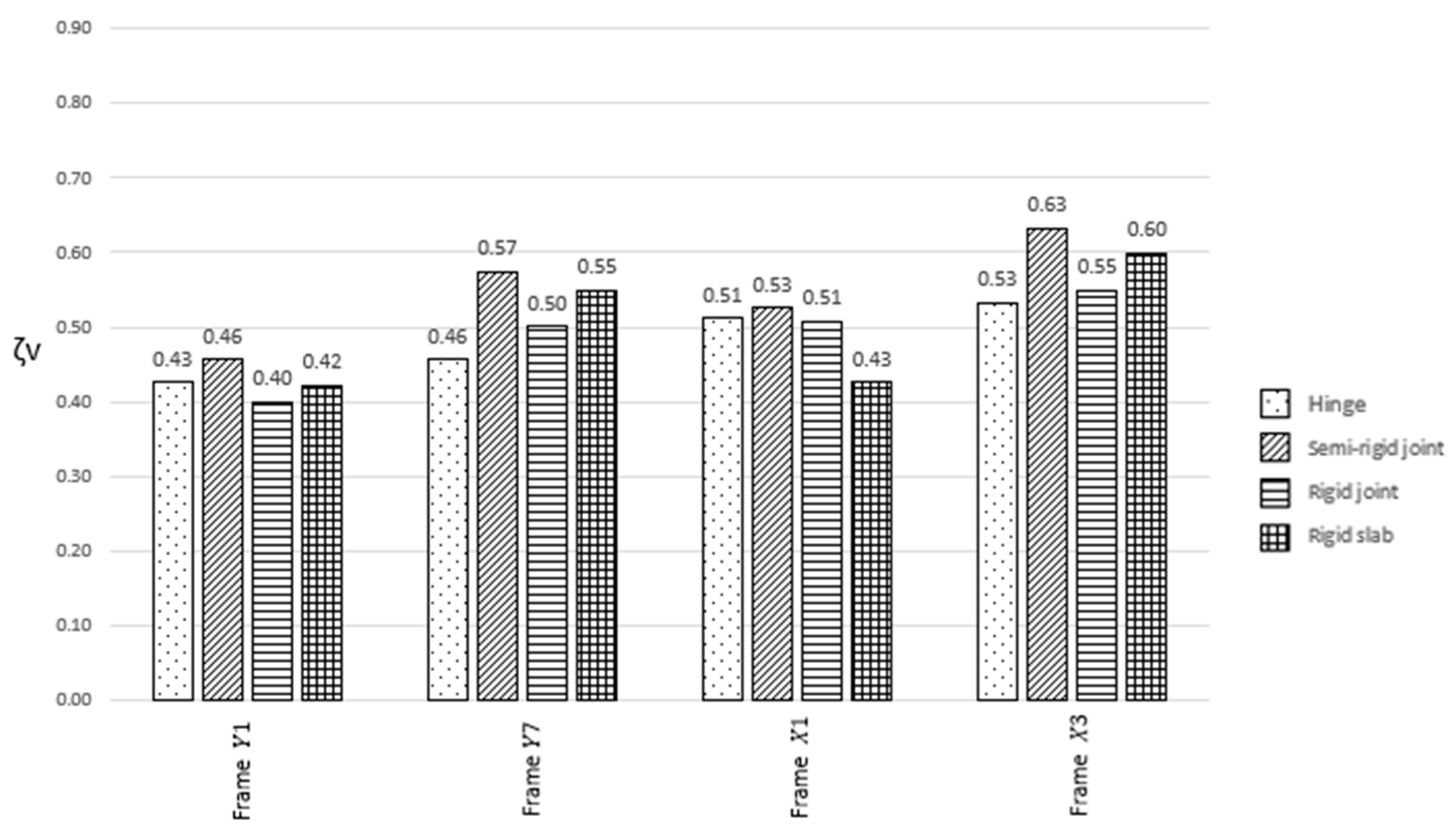
The risk indicators can be expressed in terms of either accelerations or return periods. In the first case, they can be calculated as:
where:
ζLS is the risk indicator referred to as the considered Life Safety (LS) limit state;
ag,max is the acceleration leading to the attainment of the considered limit state (i.e., the maximum seismic action that the structure can bear);
ag,NTC is the seismic reference action of the LS limit state, which is used in the design of a new building on the same ground and with the same characteristics.
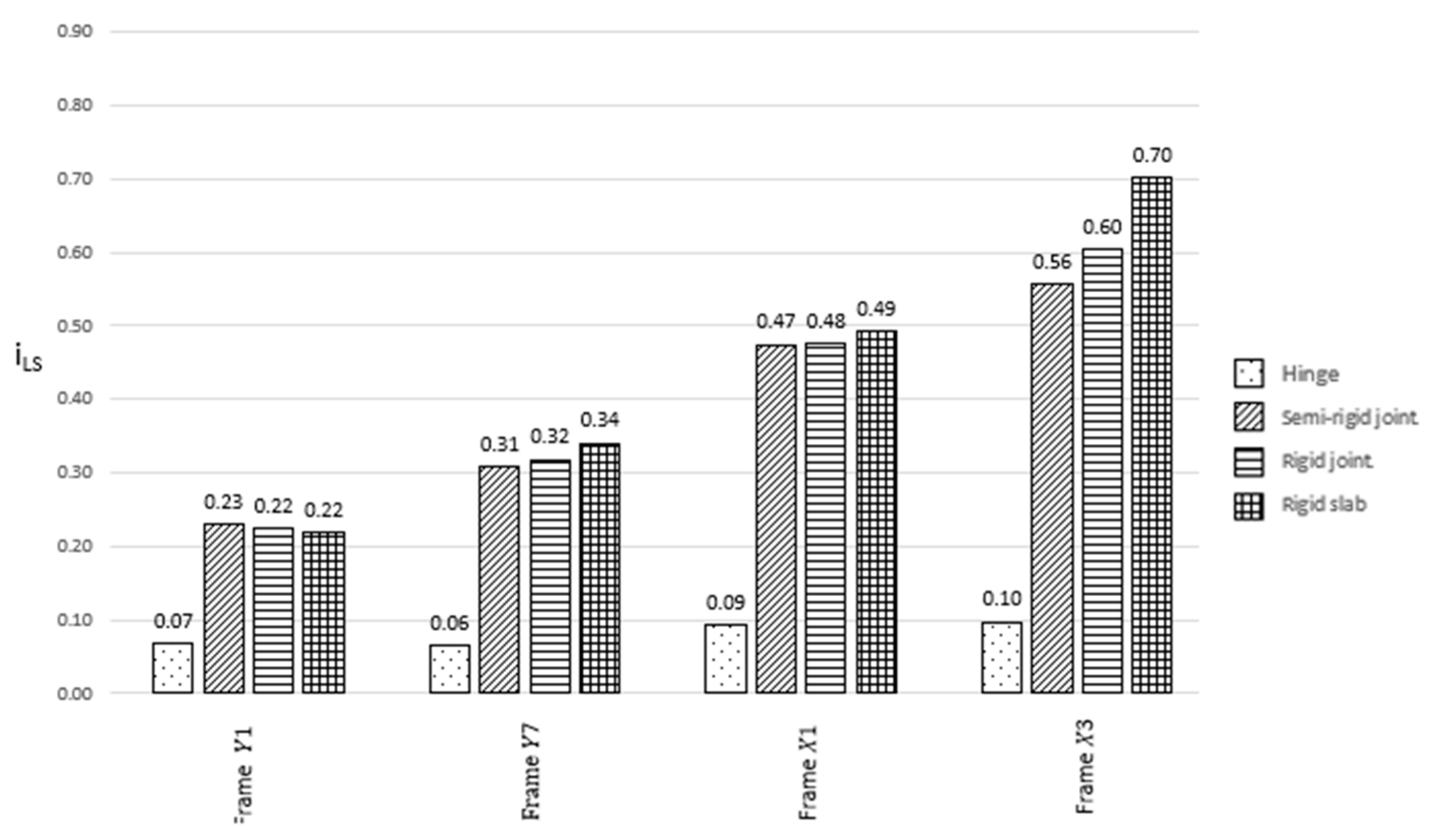
Instead, if the risk indicator is expressed in terms of the return period, it can be calculated as follows:
where:
The risk indicator can have a value greater than or equal to zero, which indicates that the structure is not able to withstand any seismic action. Contrarily, an indicator greater than 1 implies that the building fully meets the regulatory requirements to resist seismic actions. Instead, if the value is between 0 and 1, the structure has a certain resistance against seismic actions, but not enough to meet the regulatory requirements. In the cases under study, all calculated values in terms of acceleration and return period have been reported in the histograms of
Figure 16 and
Figure 17, respectively.
6. Fragility Curves
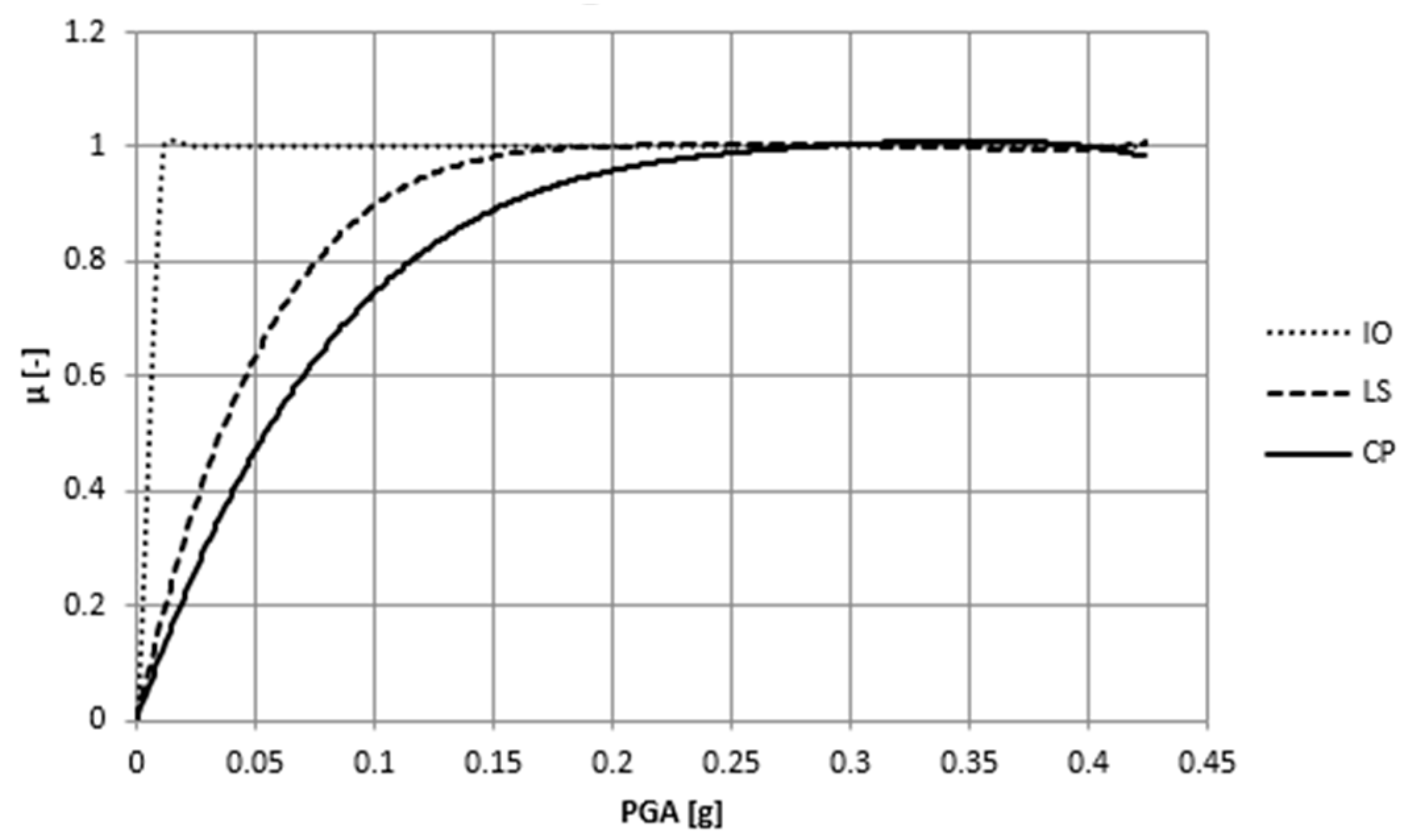
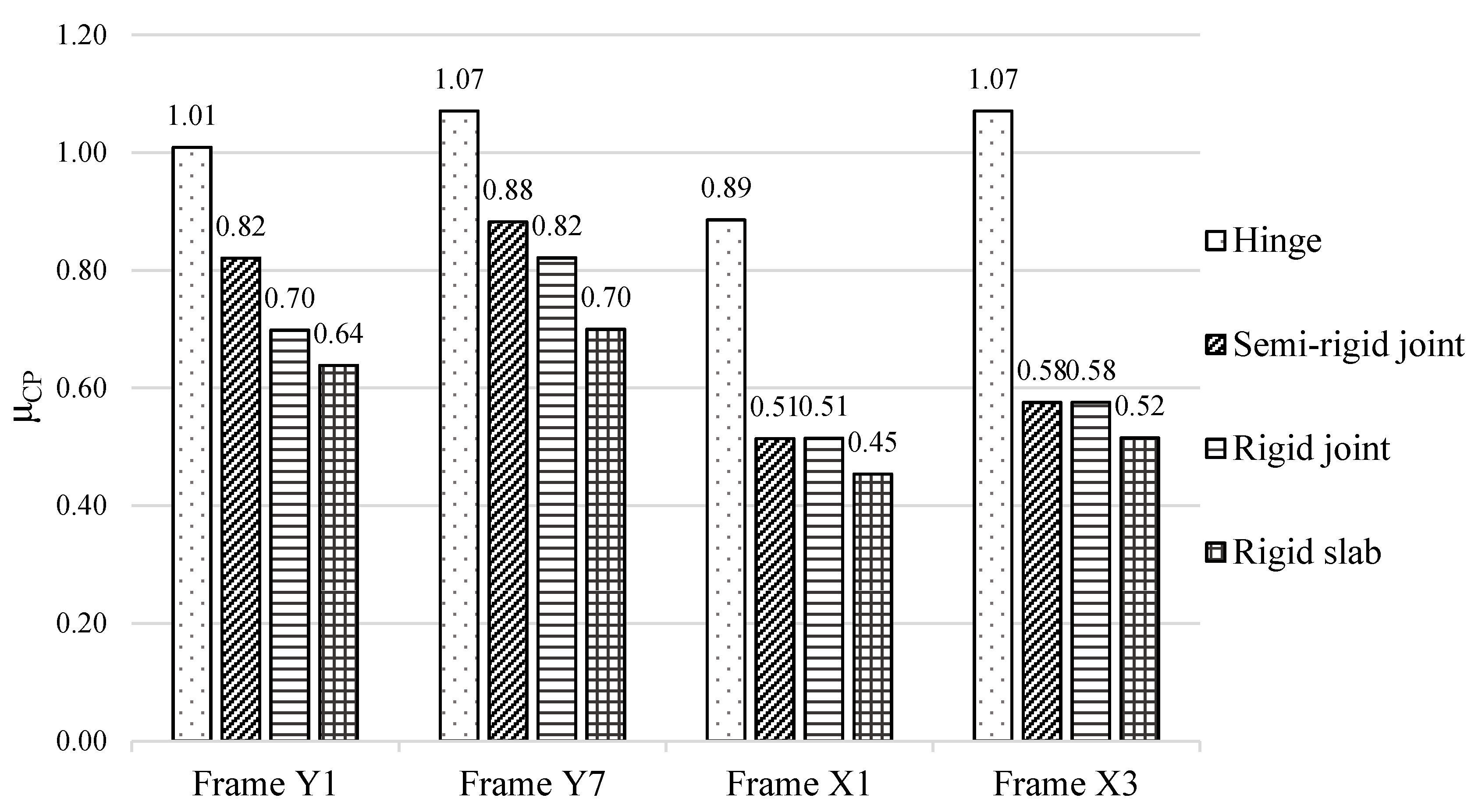
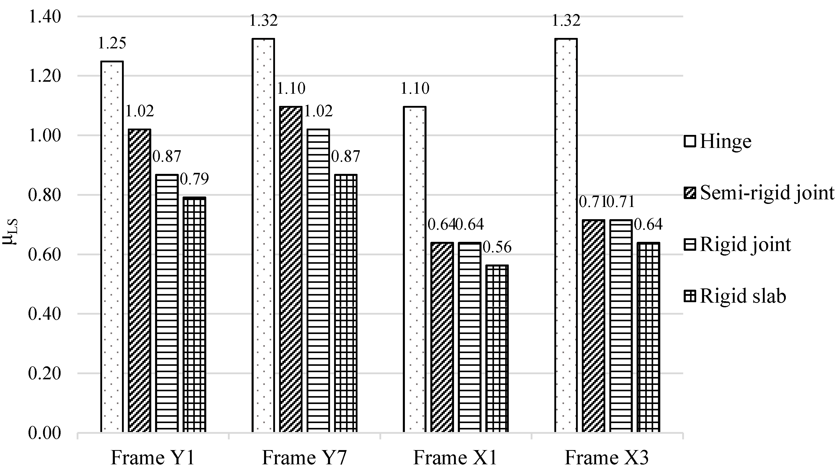
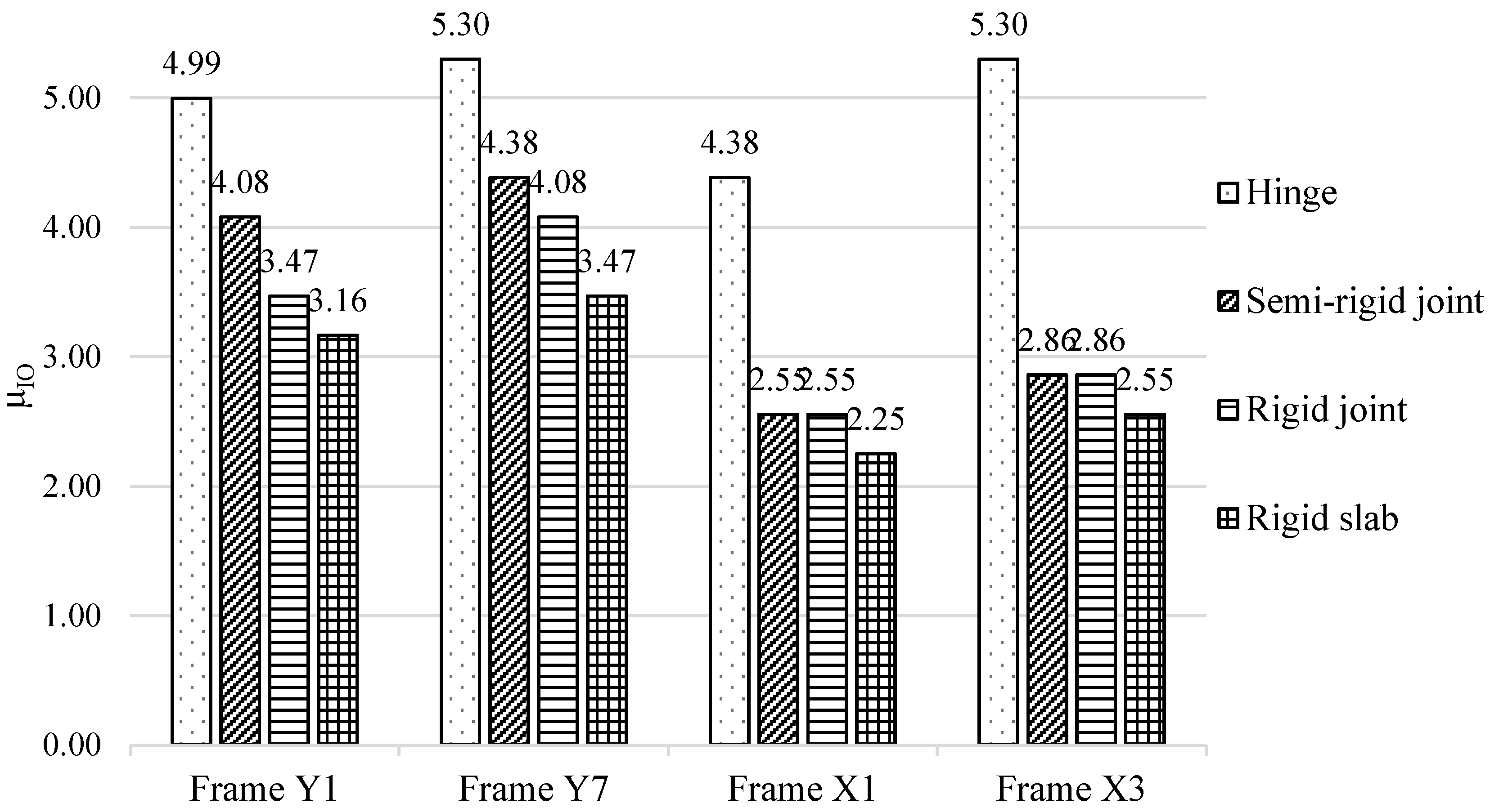
The fragility curves indicate the probability that a structural system subjected to seismic input exceeds the determined damage states. In the present study, the damage parameter μ, which is the demand-to-capacity ratio in terms of displacement, has been plotted over the PGA values representative of different Italian seismic areas.
The N2 method has been applied for different PGA values, which are representative of different response spectra, to define fragility curves. In this way, different capacity values in terms of displacement have been determined, while the demand for inter-storey drifts and displacements for each limit state (Collapse Prevention, Life Safety and Immediate Occupancy) have been assessed according to the indications of the FEMA 356 standard, as depicted in
Table 5. The fragility curves for the intermediate longitudinal frame in the
X-direction (X3) with hinged connections have been reported in
Figure 18 as a representative example.
For the structures herein examined with different joint types, the parameter μ has been calculated considering the PGA value of Ferrara, which was one of the cities most hit by the 2012 earthquake. Unlike the risk indicators, the μ factor values higher than 1 reveal the incapacity to resist seismic actions, as shown in the histograms of
Figure 19,
Figure 20 and
Figure 21 related to the three limit states considered.
7. Seismic Retrofit Intervention
As the seismic checks have returned negative results, a retrofit intervention on the columns has been foreseen. For what concerns the beams, as the checks have provided satisfactory results, the only interventions have been devoted to improving the connections with columns. For the reinforcement of columns, local interventions by steelwork have been herein analysed with reference to the static structure scheme with hinged connections. Steel angles, connected to each other by steel batten plates, have been placed at the column corners to increase the lateral confinement and, therefore, the compressive concrete strength. The addition of these longitudinal reinforcements induces an increment of the compression-bending resistance of columns, also expanding the structural ductility. The design of the intervention has been carried out considering the instability resistance of the steel–concrete reinforced cross-section.
The confinement effect of steel jacketing has been evaluated, as for ties, considering the reinforcement amount of each of the transverse directions. Section C8.7.4.6 of the explanatory circular of the NTC 2108 code [
18] provides the following formulation to consider the concrete strength increase provoked by the confinement effect of the used reinforcement type:
where:
= 2(b + h) ts/(bh) is the transverse reinforcement ratio; b and h are the base and height, respectively, of the column cross-section; ts is the thickness of the batten plates;
= 1 − [(b − 2R)2 + (h − 2R)2)/3bh] is the confinement factor in the section; R = min {length of the steel angle; 5 times ts }.
The used batten plates have the same thickness and height of angles and are placed with a pitch of 30 cm.
Table 6 summarizes the dimensions (width b
s, height h
s and thickness t
s) of the selected angles, the equivalent longitudinal reinforcement area (A
eq) and the concrete class corresponding to the increase in resistance of the basic material due to the confinement effect.
The compression-biaxial bending checks performed through the resistance domains represented in
Figure 22 emphasize that the selected local intervention has the right minimum dimensions to prevent the failure of columns.
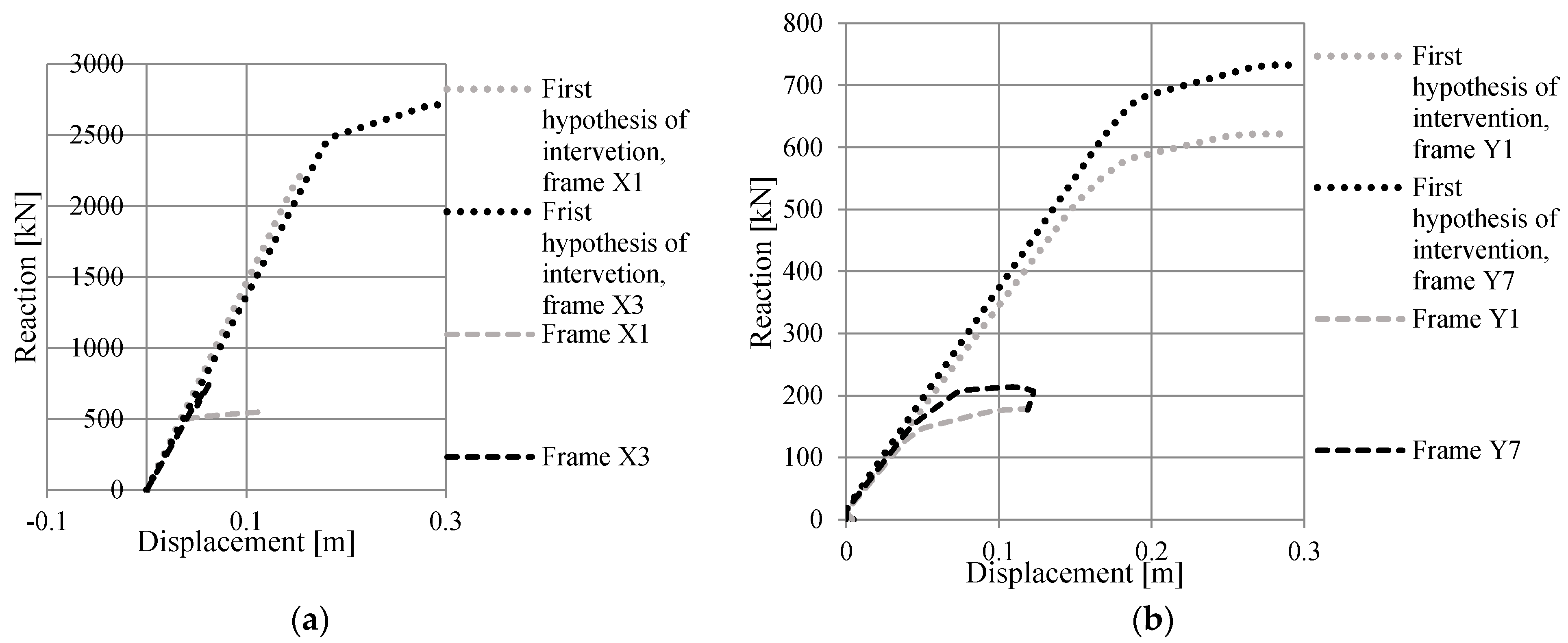
In
Figure 23, the pushover curves obtained after intervention are represented and compared with the pre-intervention ones.
The above curves show that the interventions carried out are effective at locally improving the structure’s behaviour. However, to evaluate the effectiveness of the used local techniques to also attain the global upgrading of the warehouse, the trend of the pushover curves has been assessed. From this analysis, it has been noticed that the perimeter frame (X1) in the
X-direction has a brittle behaviour without showing a plastic branch of the pushover curve. Therefore, to have a global structural behaviour, a new intervention with non-symmetrical angles has been considered (
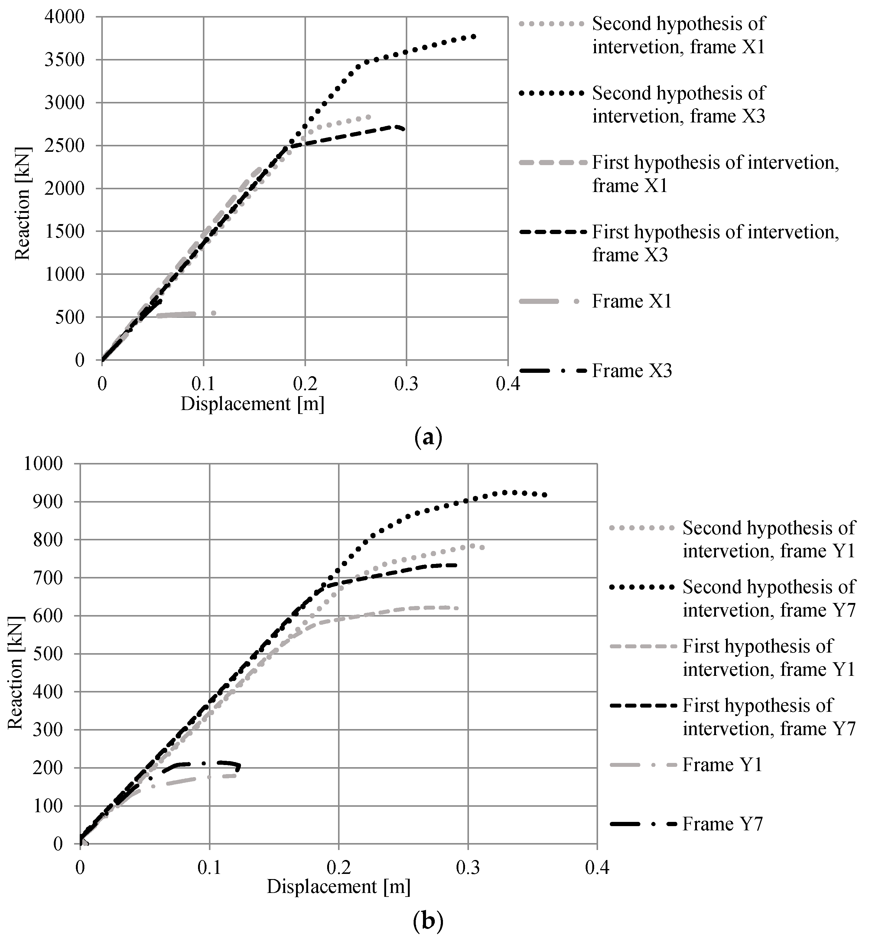
Table 7). In
Figure 24, the pushover curves derived from the second hypothesis of intervention are plotted together with those of both the original structure and the building after the first local intervention. From this picture, it is apparent that the frame X1 behaviour in the
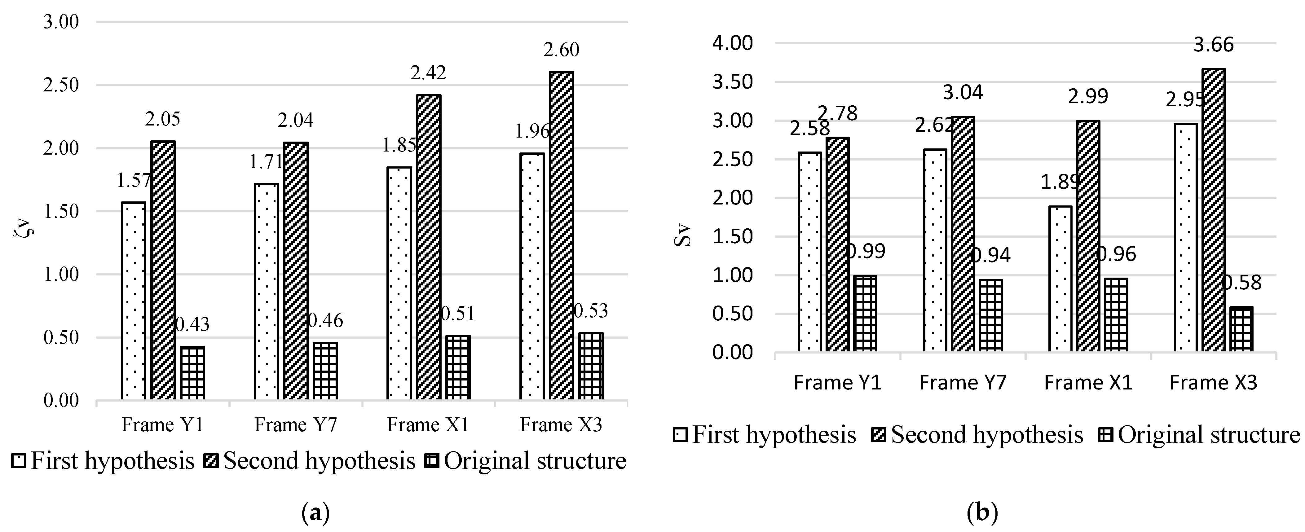
X-direction has been clearly improved since the pushover curve has a plastic field branch. In
Figure 25, the histograms of the risk indicators attained from the two interventions, as well as from those derived from the bare building with hinge connections, are reported. The results achieved undoubtedly demonstrate that the risk indicators after the second intervention, especially concerning the perimeter frame in the longitudinal direction, are significantly increased.
8. Conclusions
The seismic analysis of the precast RC warehouse herein investigated revealed the qualities and advantages of steelwork against earthquakes, which could lead to fewer collapses, victims and economic losses, as also testified by recent Italian seismic events. The use of steelwork was performed in the paper in different ways, considering interventions to both improve the rigidity of connections and reinforce the existing columns.
On the one hand, different beam-to-column connection types (hinged, semi-rigid and rigid), as well as the presence of a rigid roof, were taken into account to evaluate the change in the behaviour of the examined warehouse. All the alternatives to the widely used hinged scheme resulted in an increase in the overall rigidity of the building. This results in a design response spectrum with a small building period, which, in turn, determines higher solicitations in the linear dynamic analysis. Nonetheless, the hinge scheme still represented the most unfavourable seismic situation. This was confirmed by the calculation of the risk indicators in terms of either acceleration or return period derived from pushover analyses.
On the other hand, the structural deficiencies of the building columns directed the choice of local interventions by means of steel angles and batten plates. The first hypothesis of intervention involved the design of the smallest cross-section of the steel components in passing structural checks. Despite the ameliorative operations, the newly plotted capacity curves displayed a brittle behaviour of the longitudinal perimeter frame in the X-direction. To overcome this problem and with the purpose of having all structural frames exhibiting ductile behaviour, a second retrofitting intervention hypothesis was conceived using non-symmetrical angles for the steel jacketing. The achieved risk indicators revealed the success of the second local intervention performed. Finally, the results obtained in this work demonstrated how the well-designed local structural intervention also provides the seismic upgrading of the examined precast RC warehouse.
Author Contributions
Conceptualization, A.F.; methodology, A.F.; validation, A.F. and A.D.; formal analysis, A.F. and A.D.; investigation, A.F. and A.D.; resources, A.F.; data curation, A.D.; writing—original draft preparation, A.D.; writing—review and editing, A.F.; visualization, A.F. and A.D.; supervision, A.F.; project administration, A.F. All authors have read and agreed to the published version of the manuscript.
Funding
This research received no external funding.
Data Availability Statement
Data derived from the current study can be provided to the readers based upon their explicit request.
Acknowledgments
The research activity herein presented was developed in the framework of the WP2 line “Cartis” of the DPC-ReLUIS project, which is gratefully acknowledged.
Conflicts of Interest
The authors declare no conflict of interest.
References
- Parisi, F.; De Luca, F.; Petruzzelli, F.; De Risi, R.; Chioccarelli, E.; Iervolino, I. Field Inspection after the May 20th and 29th 2012 Emilia-Romagna Earthquakes. 2012. Available online: http://www.reluis.it (accessed on 4 October 2021).
- Di Giacomo, M. Costs of Italian Earthquakes; National Council of Engineers Study Center at the Ministry of Justice: Rome, Italy, 2014. (In Italian) [Google Scholar]
- Quaglini, V.; Pettorruso, C.; Bruschi, E.; Mari, L. Experimental and Numerical Investigation of a Dissipative Connection for the Seismic Retrofit of Precast RC Industrial Sheds. Geosciences 2022, 12, 25. [Google Scholar] [CrossRef]
- Belleri, A.; Dal Lago, B.; Rodrigues, H. (Eds.) Advances in Seismic Performance and Risk Estimation of Precast Concrete Buildings; Frontiers Media SA: Lausanne, Switzerland, 2022. [Google Scholar]
- Giovannini, D.; Vezzali, L. UNIMORE and the 2012 Emilia-Romagna earthquake. In Interventions and Research to Cope with the Emergency and Support the Recovery; University of Study of Modena and Reggio Emilia, AMP Editions: Siena, Italy, 2016. (In Italian) [Google Scholar]
- Marzo, A.; Marghella, G.; Indirli, M. The Emilia-Romagna Earthquake: Damages to Precast/Prestressed Reinforced Concrete Factories. Ing. Sismica 2012, 29, 132–147. [Google Scholar]
- Formisano, A.; Di Lorenzo, G.; Iannuzzi, I.; Landolfo, R. Seismic Vulnerability and Fragility of Existing Italian Industrial Steel Buildings. Open Civ. Eng. J. 2017, 11, 1122–1137. [Google Scholar] [CrossRef]
- Dall’Asta, A.; Landolfo, R.; Salvatore, W. Single Storey Steel Buildings for Industrial Use; Dario Flaccovio Editore: Palermo, Italy, 2009. (In Italian) [Google Scholar]
- Seismic Accessibility Working Group of Industrial Sheds and Regional Federation of Engineering Orders of Emilia-Romagna. Guidelines for Local and Global Interventions on Single-Storey Industrial Buildings Not Designed with Anti-Seismic Criteria. 2012. (In Italian). Available online: https://salute.regione.emilia-romagna.it/sanita-pubblica/piano-emergenze/files/Linee_di_indirizzo_GDL_CapannoniDEF_DPC.pdf (accessed on 4 October 2021).
- Working Group of the Italian Geotechnical Association for Industrial Buildings. Guidelines for Interventions on Single-Storey Industrial Buildings Not Designed with Anti-Seismic Criteria Affected by the 2012 May Earthquake in the Emilian Po Valley: Geotechnical Aspects. 2012. Available online: http://www.geometrimo.it/cms_rc/allegati/8242_1_1152_Linee_Guida_Capannoni.pdf (accessed on 4 October 2021). (In Italian).
- Kassem, M.M.; Nazri, F.M.; Farsangi, E.N. The seismic vulnerability assessment methodologies: A state-of-the-art review. Ain Shams Eng. J. 2020, 11, 849–864. [Google Scholar] [CrossRef]
- Aljawhari, K.; Gentile, R.; Galasso, C. A fragility-oriented approach for seismic retrofit design. Earthq. Spectra 2022, 38, 1813–1843. [Google Scholar] [CrossRef]
- Dolce, M.; Manfredi, G. (Eds.) White Paper on Private Reconstruction outside the Historical Centres in the Municipalities Affected by the Abruzzo Earthquake of 2009 April 6th; Doppiavoce Editor: Naples, Italy, 2015; ISBN 9788889972502. (In Italian) [Google Scholar]
- Mazzolani, F.M.; Formisano, A.; Vaiano, G. Seismic Upgrading of Reinforced Concrete Buildings: BRB and FRP; Costruzioni Metalliche: Milan, Italy, 2018; pp. 25–50. (In Italian) [Google Scholar]
- Ministry of Public Works. Decree 3 December 1987. Technical Standards for the Design, Execution and Testing of Prefabricated Buildings; Ordinary supplement to the “Official Gazette” no. 106 of 7-5-1988; Ministry of Public Works: Rome, Italy, 1988. [Google Scholar]
- Computer and Structures, Inc. (CSI). SAP2000 v21 Structural Analysis Program; Computer and Structures, Inc.: Berkeley, CA, USA, 2021. [Google Scholar]
- American Society of Civil Engineers (ASCE). Prestandard and Commentary for the Seismic Rehabilitation of Buildings; FEMA 356; Createspace Independent: Washington, DC, USA, 2000. [Google Scholar]
- Ministry of Infrastructure and Transport. Technical Standards for Construction; Official Gazette nr. 42 of 20-2-2018; Ministry of Infrastructure and Transport: Rome, Italy, 2018. (In Italian)
- Ministry of Infrastructure and Transport. Instructions for the Application of the New Technical Code for Constructions; Official Gazette nr. 7 of 21-2-2019; Ministry of Infrastructure and Transport: Rome, Italy, 2019. (In Italian)
- Gelfi, P. Verifica Cemento Armato Stato Limite Ultimo (VCASLU v.7.8) Software, Brescia, Italy. 2021. Available online: https://gelfi.unibs.it/software/programmi_studenti.html (accessed on 4 October 2021). (In Italian).
- Ghersi, A. The Reinforced Concrete; Dario Flaccovio Editore: Palermo, Italy, 2012. (In Italian) [Google Scholar]
Figure 1.
Precast RC frame with a simply supported beam.
Figure 1.
Precast RC frame with a simply supported beam.
Figure 2.
Collapse of infill panels [
1].
Figure 2.
Collapse of infill panels [
1].
Figure 3.
Damage to columns [
1].
Figure 3.
Damage to columns [
1].
Figure 4.
Seismic deformations of steel scaffolding systems [
1].
Figure 4.
Seismic deformations of steel scaffolding systems [
1].
Figure 5.
Plan layout of the building.
Figure 5.
Plan layout of the building.
Figure 6.
Transverse section.
Figure 6.
Transverse section.
Figure 7.
Longitudinal section.
Figure 7.
Longitudinal section.
Figure 8.
Three-dimensional FEM model.
Figure 8.
Three-dimensional FEM model.
Figure 9.
Resistance domains for columns of the static scheme with hinges.
Figure 9.
Resistance domains for columns of the static scheme with hinges.
Figure 10.
Resistance domains for columns of the static scheme with semi-rigid joints.
Figure 10.
Resistance domains for columns of the static scheme with semi-rigid joints.
Figure 11.
Resistance domains for columns of the static scheme with rigid joints.
Figure 11.
Resistance domains for columns of the static scheme with rigid joints.
Figure 12.
Resistance domains for columns of the static scheme with roof rigid slab.
Figure 12.
Resistance domains for columns of the static scheme with roof rigid slab.
Figure 13.
Non-linear static curves in the transverse (X) direction.
Figure 13.
Non-linear static curves in the transverse (X) direction.
Figure 14.
Non-linear static curves in the longitudinal (Y) direction.
Figure 14.
Non-linear static curves in the longitudinal (Y) direction.
Figure 15.
Seismic safety factors in terms of displacement.
Figure 15.
Seismic safety factors in terms of displacement.
Figure 16.
Seismic safety factors in terms of acceleration.
Figure 16.
Seismic safety factors in terms of acceleration.
Figure 17.
Seismic safety factors in terms of the return period.
Figure 17.
Seismic safety factors in terms of the return period.
Figure 18.
Fragility curves of the intermediate frame in the X-direction with hinged connections.
Figure 18.
Fragility curves of the intermediate frame in the X-direction with hinged connections.
Figure 19.
Damage factors of the warehouse with different connection types at the CP limit state.
Figure 19.
Damage factors of the warehouse with different connection types at the CP limit state.
Figure 20.
Damage factors of the warehouse with different connection types at the LS limit state.
Figure 20.
Damage factors of the warehouse with different connection types at the LS limit state.
Figure 21.
Damage factors of the warehouse with different connection types at the IO limit state.
Figure 21.
Damage factors of the warehouse with different connection types at the IO limit state.
Figure 22.
Resistance domains of reinforced columns following the first hypothesis of intervention.
Figure 22.
Resistance domains of reinforced columns following the first hypothesis of intervention.
Figure 23.
Comparison of pushover curves before and after local intervention in the X-direction (a) and the Y-direction (b).
Figure 23.
Comparison of pushover curves before and after local intervention in the X-direction (a) and the Y-direction (b).
Figure 24.
Comparison of pushover curves before and after both local intervention hypotheses in the X-direction (a) and the Y-direction (b).
Figure 24.
Comparison of pushover curves before and after both local intervention hypotheses in the X-direction (a) and the Y-direction (b).
Figure 25.
Histograms displaying risk indicators in terms of accelerations (a) and displacement (b) calculated for selected X and Y frames of the original structure, as well as for the first and second intervention hypotheses.
Figure 25.
Histograms displaying risk indicators in terms of accelerations (a) and displacement (b) calculated for selected X and Y frames of the original structure, as well as for the first and second intervention hypotheses.
Table 1.
Mechanical properties of RC components.
Table 1.
Mechanical properties of RC components.
| Structural Element | Concrete
Class | | | E |
|---|
| (MPa) | (MPa) | (MPa) |
|---|
| RC Column | C35/45 | 35.00 | 23.33 | 34,007.00 |
| Precast RC Beam | C40/50 | 40.00 | 26.66 | 38,214.00 |
Table 2.
Mechanical properties of mild steel rebars.
Table 2.
Mechanical properties of mild steel rebars.
Structural
Element | | | E |
|---|
| (MPa) | (MPa) | (MPa) |
|---|
| FeB44K | 430.00 | 373.91 | 210,000.00 |
Table 3.
Modal analysis results.
Table 3.
Modal analysis results.
| Vibration Mode | Hinge | Semi-Rigid Joints | Rigid Joints | Rigid Slab |
|---|
| 1° | T = 2.29 s | T = 1.37 s (−40%) | T = 1.16 s (−50%) | T = 1.13 s (−51%) |
| Mx = 74% | Mx = 71% | Mx = 72% | Mx = 78% |
| My = 0% | My = 0% | My = 0% | My = 0% |
| Rz = 0% | Rz = 0% | Rz = 0% | Rz = 0% |
| 2° | T = 2.18 s | T = 1.33 s (−39%) | T = 1.11 s (−49%) | T = 1.05 s (−52%) |
| Mx = 0% | Mx = 0% | Mx = 0% | Mx = 0% |
| My = 0% | My = 0% | My = 0% | My = 0% |
| Rz = 18% | Rz = 17% | Rz = 18% | Rz = 66% |
| 3° | T = 2.04 s | T = 1.27 s (−38%) | T = 1.04 s (−49%) | T = 1.03 s (−50%) |
| Mx = 0% | Mx = 4% | Mx = 0% | Mx = 0% |
| My = 99% | My = 0% | My = 89% | My = 100% |
| Rz = 0% | Rz = 0% | Rz = 0% | Rz = 0% |
Table 4.
Bending moment checks of beams.
Table 4.
Bending moment checks of beams.
| Static Scheme | L-Shaped Beam | Inverted T-Shaped Beam | Variable Section Beam |
|---|
| MEd,mid (kNm) | MEd,sup (kNm) | MEd,mid (kNm) | MEd,sup (kNm) | MEd,mid (kNm) | MEd,sup (kNm) |
|---|
| Hinge | 272.9 | 0.0 | 124.4 | 0.0 | 1347.6 | 0.0 |
| Semi-rigid joint | 232.5 | 95.4 | 125.4 | 174.6 | 1238.8 | 82.2 |
| Rigid joint | 170.9 | 137.1 | 108.8 | 260.5 | 967.5 | 152.4 |
| Rigid slab | 183.7 | 217.1 | 102.9 | 222.9 | 637.2 | 39.6 |
| Resistant moment | MRd,mid (kNm) | MRd,sup (kNm) | MRd,mid (kNm) | MRd,sup (kNm) | MRd,mid (kNm) | MRd,sup (kNm) |
| | 623 | 623 | 873 | 873 | 2170 | 674 |
Table 5.
Inter-story drifts and displacements for different limit states according to FEMA 356 prescriptions.
Table 5.
Inter-story drifts and displacements for different limit states according to FEMA 356 prescriptions.
| θCP | θLS | θIO | dCP (m) | dLS (m) | dIO (m) |
|---|
| 0.015 | 0.012 | 0.003 | 0.1005 | 0.0804 | 0.0201 |
Table 6.
Local intervention technique with steel angles and batten plates—first hypothesis.
Table 6.
Local intervention technique with steel angles and batten plates—first hypothesis.
| Column Type | bs (mm) | hs (mm) | ts (mm) | Aeq (cm2) | Concrete Class |
|---|
| A-Corner | 60 | 60 | 5 | 23 | C45/55 |
| A-longitudinal | 60 | 60 | 10 | 34.9 | C50/60 |
| A-transverse | 60 | 60 | 10 | 34.9 | C50/60 |
| B-Central | 60 | 60 | 10 | 34.9 | C50/60 |
Table 7.
Local intervention technique with steel angles and batten plates—second hypothesis.
Table 7.
Local intervention technique with steel angles and batten plates—second hypothesis.
| Column Type | bs (mm) | hs (mm) | ts (mm) | Aeq (cm2) | Concrete Class |
|---|
| A-Corner | 120 | 60 | 5 | 32.5 | C40/50 |
| A-longitudinal | 60 | 60 | 10 | 34.9 | C45/55 |
| A-transverse | 60 | 110 | 10 | 34.9 | C50/60 |
| B-Central | 80 | 110 | 10 | 40.2 | C50/60 |
| Publisher’s Note: MDPI stays neutral with regard to jurisdictional claims in published maps and institutional affiliations. |
© 2022 by the authors. Licensee MDPI, Basel, Switzerland. This article is an open access article distributed under the terms and conditions of the Creative Commons Attribution (CC BY) license (https://creativecommons.org/licenses/by/4.0/).


