Article

Experimental Investigation of Beams Reinforced with Carbon 2D-Netzgitterträger Reinforcement

1
Institute of Concrete Structures, Technische Universität Dresden, 01219 Dresden, Germany
2
Institute of Textile Machinery and High Performance Material Technology, Technische Universität Dresden, 01069 Dresden, Germany
*
Author to whom correspondence should be addressed.
Buildings 2023, 13(10), 2552; https://doi.org/10.3390/buildings13102552
Submission received: 4 September 2023 / Revised: 27 September 2023 / Accepted: 8 October 2023 / Published: 9 October 2023
(This article belongs to the Special Issue Research on the Performance of Non-metallic Reinforced Concrete)

Abstract

:
The increasing popularity of carbon-reinforced concrete (CRC) is attributed to its exceptional tensile properties, low density, no corrosion phenomenon, and remarkable flexibility, allowing it to be easily shaped into various forms. However, there is a pressing need to explore this innovative and sustainable alternative to traditional steel reinforcement. This motivates research and investigation of the feasibility of using a special 2D Netzgitterträger (NetzGT) reinforcement system, featuring a net-shaped fabricated textile made of multiple diagonally offset rovings with overlapping edge strands, as a viable alternative to traditional steel reinforcement in concrete beams. This 2D NetzGT reinforcement system has also been transformed into a 3D configuration for the development of a hollow core slab system. It is manufactured from carbon rovings with three different diagonal angles of 50°, 60°, and 70°. Laboratory experiments were conducted to assess the mechanical behavior of beams reinforced with the 2D NetzGT reinforcement. Tensile tests on strands were also performed with an increasing number of overlapped rovings to analyze their tensile strength. Additionally, single yarn pull-out tests were also conducted to examine the influence of the roving angle on the bond strength between the carbon textile roving and the concrete matrix.

1. Introduction

Cement and concrete are necessary building components of our modern construction society. They are the most often used construction materials due to their wide resources, simplicity of usage, and adaptability [1,2,3]. In addition to the remarkable benefits of the steel-reinforced concrete, it also comes with significant disadvantages. For instance, a concrete cover layer of up to 6 cm thickness is typically added to the reinforcing steel primarily for corrosion and fire protection, rather than structural necessity. This inefficient material consumption with very high CO2 cement content is criticized today as a “climate-damaging resource consumer” [4]. According to 2019 estimates, CO2 emissions from their usage, transportation, production, and demolition account for about 10% of all energy-related CO2 emissions worldwide [5]. The rapid expansion of population and urbanization over the coming decades worldwide suggests that there is an urgent need for ways to reduce the negative effects of cement and concrete on the environment and climate change [6]. Researchers have been exploring alternative materials and methods, prompting a search for more eco-friendly alternatives and innovative techniques to address the challenges of construction in a sustainable manner. For instance, one of the approaches is the use of high-strength fiber-reinforced materials that can lead to efficient resource utilization while maintaining the desired structural performance [7].
Concrete, particularly in steel-reinforced concrete structures, effectively handles compression while steel is relied upon to withstand tension. Similar to steel-reinforced concrete structures, carbon textile-reinforced concrete (CTRC) structures use carbon textile reinforcement to provide the necessary tensile strength [8]. In carbon textile reinforcement, carbon fibers are initially produced in the form of filaments. These filaments are then grouped to form yarns or rovings and finally, rovings are then grouped in a specific pattern to form strands [9,10]. The carbon strands are arranged in a mat-like structure to provide specific mechanical properties. This CTRC composite offers several advantages over traditional steel reinforcement. Firstly, carbon fibers have a significantly higher tensile strength and lower density compared to steel, allowing for the development of lighter and more slender structural elements [11,12]. The CTR exhibits a tensile strength of approximately 3500 MPa, resulting in a load-bearing capacity up to six times greater than that of conventional steel reinforcement, which is approximately 550 MPa. This enables the utilization of significantly reduced amounts of reinforcement material and leads to the reduced overall weight of the structure [13]. Furthermore, it offers the advantage of being corrosion resistant, as opposed to steel, which is prone to corrosion over time. As a result, concrete cover is only necessary to ensure bond strength [14]. Furthermore, the high flexibility of CTR composite also allows for easier shaping and molding of complex structural geometries [15]. These positive effects not only enhance CTR’s suitability for new construction projects but also for the repair of old buildings [16,17].
Over the past decade, there has been a surge of interest in exploring the potential of CTRC through various projects. These initiatives have aimed to investigate and utilize the capabilities of CTRC as a construction material [18]. The outcomes of these investigations have provided valuable insights into the behavior, structural integrity, and potential applications of CTRC. Notably, in recent years, the findings and knowledge gained from these projects have led to the full-scale implementation of CTRC in practical applications. One impressive example is the construction of CUBE, the world’s first carbon-reinforced building. The CUBE was recently constructed by the Institute of Concrete Structures (IMB), Technische Universität Dresden, Germany; see Figure 1 [14,19]. Furthermore, the utilization of carbon textile reinforcement provides enhanced geometrical flexibility, enabling the carbon grid-like structure to be easily molded, bent, or twisted into diverse shapes. There has been a significant transformation in the application of carbon textile reinforcement within the realm of construction material, leading to innovative uses such as in the construction of hollow core slabs and walls [15,20,21]. This characteristic has sparked significant interest within the construction industry, as it allows for the creation of novel structural elements and designs, capitalizing on the advantageous properties of carbon reinforcement. One of the examples of this is the construction of aesthetic Pavilions in Chemnitz, Germany [22]. The exceptionally lightweight and slender precast bridge in Albstadt, Germany and many other structures have been constructed by using CTRC as the primary material [23,24,25,26,27,28,29,30].
While several research efforts have explored the integration of textile reinforcement in various forms within concrete structures [31], this study introduces a novel approach by creating a specific textile reinforcement configuration that offers dual functionality. The primary objective of this research is to show the potential of a textile reinforcement structure that can act as a flexural reinforcement when placed horizontally within concrete beams, and as a shear reinforcement when placed vertically. This innovative reinforcement concept represents a significant departure from traditional steel reinforcement and aims to optimize structural efficiency by seamlessly combining two essential reinforcement functions within a single, tailored textile configuration.

2. Materials, Test Program, and Test Setups

2.1. Materials

The experimental investigation used a single concrete mix of grade 30/37 throughout the study. The composition of the design mix can be found in Table 1. Concrete properties were evaluated by conducting tests on 150 × 300 mm cylinders after 29 days of curing. The average dry compressive strength achieved was 40 MPa. The concrete was supplied by the local company informbeton GmbH [32]. A single batch of concrete was used for the manufacturing of single yarn pull-out specimens, bending test specimens, and shear test specimens.
Textile rovings were manufactured by the Institute of Textile Machinery and High-Performance Material Technology (ITM) using carbon fiber heavy tows (CFHT) Teijin Tenax-E STS 40 F13 48 K 3200tex (Teijin Carbon Europe GmbH, Wuppertal, Germany) with properties according to [9] in combination with impregnation material of TECOSIT CC 1000 (CHT Germany GmbH, Tübingen, Germany), which is a polymeric dispersion with a solid content of approx. 50% [9,33]. The straight rovings were manufactured by impregnating the CFHT with the foulard technique and consolidated for 10 min at approx. 180° by using infrared modules Typ IRDS750 SM 3 kW 400 V fast middlewave (OPTRON GmbH, Garbsen, Germany) at 90% power (2.7 kW). Straight rovings were specifically produced to examine the tensile strength of rovings. Bent rovings were extracted from the 2D NetzGT reinforcement structrure with three different angles of 50°, 60°, and 70° to investigate the influence of the angle of roving on the bond strength.
The 2D NetzGT reinforcement is a continuous textile net-shaped non-crimp fabric reinforcement made of multiple diagonally offset carbon fiber rovings [15]. For this fundamental study, 2D NetzGT reinforcement structures were produced with the support of manual yarn placement of impregnated rovings on a rack and subsequent consolidation in a champer oven SV 9670/30 MK II (Arnold Schröder Industrieöfen GmbH, Flörsheim am Main, Germany) at 180 °C for 30 min. In principle, the textile reinforcement structure can be produced using a modified highly productive multiaxial warp knitting process in combination with the further developed warp yarn manipulation method and subsequent impregnation and consolidation of the textile structure [34]. The reinforcement is manufactured in a zigzag pattern, starting at the upper end and slanting diagonally toward the lower end. It then transitions into a straight length of 160 mm, followed by a diagonal inclination from the lower end to the upper end. This pattern continues in a repeated sequence resulting in a zigzag structure as shown in Figure 2. The edge-overlapped rovings employed in the construction of NetzGT reinforcement are considered tension reinforcement, and therefore, the number of these rovings has a significant impact on the tensile strength of the reinforcement. For this reason, the investigation was carried out on strands with 1,3,4,5, and 6 overlapped rovings to examine their impact on the 2D NetzGT reinforcement.

2.2. Test Program and Test Setups

2.2.1. Yarn Tension Test

Tension tests were performed on the straight roving with a linear mass density of 3200tex. These specimens were labeled as “R-X,” with “R” denoting roving and “X” representing the number of rovings incorporated in each strand specimen. Four distinct configurations were tested, consisting of 1, 3, 5, and 6 rovings in the specimens; see Table 2. Under each configuration, five specimens were taken into account for statistical analysis. For anchoring purposes, Sikadur-30, an epoxy resin-based composition from the Sika company, was skillfully employed to establish a strong bond between the resin embedded rovings and metal plates [35]. The testing process involved subjecting the specimens to a controlled loading rate of 2 mm/min (0.03 mm/s) while their free length remained at 100 mm as shown in Figure 3. Through this testing setup, the objective was to investigate the tensile properties and behavior of the strands under varying numbers of rovings.

2.2.2. Single Yarn Pull-Out Test

The single yarn pull-out (YPO) test was conducted to examine the impact of the roving angle on the bond strength and anchorage behavior of the roving in the concrete. In this test, the single rovings were embedded in concrete cubes at three different angles of 50°, 60°, and 70°. One of the main reasons for examining a curved or bent roving is to assess its ability to bear loads within the center region of the NetzGT reinforcement. A total of three specimens were tested at each roving angle during the experiment. The roving used had an average diameter of 3 mm. To conduct the tests, the YPO in [36] was followed with certain modifications due to the difficulties encountered in maintaining consistent dimensions; see Figure 4. Foam rubber was employed at the beginning and end of the rovings to prevent stress concentration and ensure a fixed tail length for all specimens, despite the varying angles. Furthermore, all the concrete cubes were equipped with cast-in transport bolts. These bolts served the purpose of connecting the upper and lower parts during transportation and preparation, as well as preventing premature failure.

2.2.3. Tension Test on 2D NetzGT

A four-point bending test according to RILEM RC5 [37] was performed on a beam reinforced with 2D NetzGT reinforcement to evaluate the tensile behavior of NetzGT reinforcement and failure characteristics of the beam. The test setup was modified for 2D NetzGT reinforcement with a bond breaker length of 10 mm as shown in Figure 5. This modification was carried out to intentionally lower the beam’s stiffness at the center of the beam and ensure the same crack initiation location across all specimens. The beam test specimens were tested in a universal testing machine. The test specimen consists of two identical reinforced halves of a beam connected by the reinforcement for the tension test and a steel hinge for the transfer of the compressive force. The beam was reinforced with 2D NetzGT reinforcement as shown in Figure 2b. The reinforcement in the test setup was laid horizontally with a width of 300 mm. The test setup uses the 2D NetzGT reinforcement with the use of three, four, and six edge-overlapped roving strands with three different roving angles of 50°, 60°, and 70°, respectively; see Table 3. The test specimens were labeled as B-X-Y, where the first letter B represents the “beam” specimen, X represents the angle of textile roving in the NetzGT reinforcement, and Y represents the number of overlapped edge rovings. This test approach aimed to evaluate the impact of varying roving angles and the number of overlapped edge rovings on the tensile strength of NetzGT reinforcement. The beam specimens were placed on a testing apparatus designed for four-point bending tests. This apparatus consisted of supports located at both ends of the beam, along with two loading points positioned between the supports. Five Linear Variable Differential Transformers (LVDTs) were used for measuring displacement at different points of the beam.

2.2.4. Shear Test

Three-point bending tests were conducted on beams that were reinforced with a similar 2D NetzGT reinforcement. However, in this test, the reinforcement was placed vertically with a height of 300 mm rather than horizontally; see Figure 6. The main objective of the shear test was to observe the failure behavior of the beam when the 2D NetzGT reinforcement was positioned vertically as shear reinforcement and to examine the effect of the roving angle and the number of overlapped edge rovings on the maximum load. The shear span to depth ratio (a/d = 600/320) was kept constant as 1.9 for all the test specimen. The vertical load was applied at a constant speed of 1 mm/min (0.017 mm/s). The test setup uses the 2D NetzGT reinforcement with three and four overlapped edge rovings, with two different roving angles of 50° and 60°; see Table 4. The test specimens had the same labeling as the four point bending test, i.e., B-X-Y, where the first letter B represents “beam” specimen, X represents roving angle in the NetzGT reinforcement, and Y represents the number of overlapped edge rovings. Five LVDTs were attached to the beam for measuring displacement at various points.

3. Results and Discussion

3.1. Yarn Tension Test

The load-displacement curves for the strands that are tested under tension are illustrated in Figure 7. In the case of the R_1 specimen, where only one roving was used, the curves exhibited a linear behavior without having any drop in the curve, suggesting a well-distributed load over the specimen’s length. However, with an increase in the number of rovings to three in the strand (R_3 specimen), there were noticeable changes in the load-bearing behavior, resulting in sudden fluctuations in the curves. This is due to the fact that the individual yarns are not uniformly stretched within the specimen; thus, not all of them contribute equally to the load transfer. Moreover, the presence of multiple rovings in the strand enhanced the overall capacity of the strand, leading to an increase in the maximum force. This trend continues as the number of rovings further increased to five and six in the strand (R_5 and R_6 specimens). Additionally, it can also be seen from the curves that the stiffness increases as the number of rovings in the strand increases.
It can be interpreted from Figure 8 that the increase in the number of rovings in the strands leads to a significant increase in its ultimate load-carrying capacity. For instance, the R_1 specimen, containing only a single roving, exhibits a peak tensile force of 6.6 kN, while the R_3 specimen demonstrates a tensile breaking force of 9.7 kN, marking an impressive increase of approximately 47% compared to R_1. The R_5 specimen shows even more significant improvement, with a maximum tensile force of 10.9 kN, representing a remarkable 65% increase over the R_1 specimen. The R_6 specimen, comprising six rovings in the strand, achieves the highest tensile force at 13.8 kN, signifying a substantial increase of around 109% compared to the R_1 specimen. This observed increase in ultimate load-carrying capacity, or tensile force, with the addition of more rovings in the strand can be attributed to several factors. First, the overall cross-sectional area of the strand increases when more rovings are grouped together. This means that a greater number of individual fibers contribute to the load-bearing capacity of the strand. Moreover, the presence of multiple rovings enhances the load-sharing capacity of the strand. If one roving experiences a localized weakness or failure, the others can compensate, preventing overall failure and enabling the strand to withstand higher loads. Additionally, the interaction between the rovings creates a synergistic effect. As the rovings are laid together, their alignment and interaction improve load distribution along the length of the strand, allowing it to withstand higher forces. In conclusion, the increase in the number of rovings not only provides more fibers to share the load but also ensures more even load distribution and offers redundancy in case of fiber failure. This combined effect leads to a significant enhancement in the ultimate load-carrying capacity of strands with more rovings.
These data also clearly highlight the increase in standard deviation with an increase in the number of rovings in the strand and can be attributed to greater variability in tension distribution within the strands; see Table 5. When more rovings are incorporated to produce a strand, then each roving might experience slightly different conditions during the manufacturing process, leading to variations in their tensile properties. These variations can accumulate and result in differences in tension across the strands. As the number of rovings increases, the potential for these small differences to add up also increases, which is reflected in the higher standard deviation values observed in the specimens with more roving, such as specimens R_5(2.01) and R_6(2.68) as compared to specimens R_1(0.39) and R_3(0.79).

3.2. Single Yarn Pull-Out Test

There are multiple factors that can affect the maximum pull-out load in a YPO test, such as geometry, bending radius, profile, embedment length, steepness of the roving (angle of the roving), and friction between the roving and concrete [38]. In this study, the only variable that was researched in the YPO test was the inclination of textile roving while keeping all the other parameters constant. The test details and labeling of the specimen can be found in Section 2.2.2. The 50° roving shows an average pull-out force of 2.7 kN, the 60° roving shows 3.5 kN, and the 70° roving shows 2.5 kN; see Figure 9. It has been observed that the force increases with the angle of the roving increasing from 50° to 60°, and then decreases with a further increase in the angle from 60° to 70°.
When the embedment angle of the textile roving is increased from 50° to 60°, a notable 29.6% increase in the maximum pull-out force is observed, with values of 3.5 kN at 60° compared to 2.7 kN at 50°. This increase in force can be attributed to the increased friction and improved interlocking. As the angle of embedment increases, the frictional forces between the roving and the surrounding matrix also increases and this is due to the increase in the effective bonding surface area [39]. Additionally, the roving assumes a more oblique or inclined orientation within the matrix at 60° as opposed to 50°. This inclined orientation creates a challenging path for the roving to be extracted from the concrete matrix, further contributing to the increased pull-out force. Another contributing factor to the increased pull-out force is mechanical interlocking. With a larger embedment angle, the roving has more opportunities to mechanically interlock with the surrounding matrix. This interlocking mechanism significantly enhances the bond strength, consequently elevating the maximum pull-out force in the 60° specimen.
However, when the embedment angle of the textile roving is further increased from 60° to 70°, there is a notable 40% decrease in the maximum pull-out force, recording values of 2.5 kN at 70° compared to 3.5 kN at 60°. This decline in force can be attributed to stress concentration. At steeper angles, such as 70°, stress concentration becomes more pronounced around the roving–matrix interface, resulting in an overall reduction in the pull-out force.
In conclusion, the experimental results clearly indicate that a 60° textile roving angle provides a significantly higher pull-out force compared to other angles tested in this investigation. This suggests that a 60° textile roving angle can be considered an optimized configuration. Nevertheless, conducting an experimental study that spans a range of roving angles from 50° to 70° would provide valuable insights into the variations in pull-out force.

3.3. Tension Test on 2D NetzGT

The main objective of the four-point bending test is to determine the total tensile capacity of a 2D NetzGT reinforcement. The tensile forces are mainly transmitted in the overlapped edge strands, with a smaller contribution originating from the intersecting threads within the central region. Thus, a flat 2D NetzGt can be tested to obtain the load-bearing capacity of the 3D NetzGT. By defining the inner lever arm in a bending test, the force can be determined. The inner lever arm is defined with the help of a metal joint in the compression zone, so the tensile force in the reinforcement can be determined from the bending test as shown in Figure 10. The tension strands in the NetzGT were modified by varying the number of overlapping edge rovings. Additionally, the angle of orientation for the roving was also altered, with variations at 50°, 60°, and 70°. All of the test specimens show bending failure with a single big crack starting from the bottom and growing to the steel hinge of the beam.
Figure 11 illustrates the relationship between the force and displacement for various beam specimens generated during the beam loading process. All the tested specimens exhibit a similar behavior, characterized by an initial sudden drop in force at the beginning of loading, which corresponds to the formation of the first crack. Subsequently, the force increases until reaching its maximum value. However, there are intermittent drops in force between the first crack load and the maximum load. Furthermore, all the tested specimens show an increase in the force after the occurrence of the first crack. This indicates that the NetzGT reinforcement within the beam specimens became activated, contributing to an increase in the load bearing capacity. By maintaining the identical roving angle within the specimen and increasing the number of rovings in the strand, an increase in the stiffness of specimen B-60-6 compared to specimen B-60-3 can be noticed. This can be attributed to the cross-sectional area of the strand. When there are more rovings in the strand, there are more fibers providing reinforcement, leading to improved load-bearing capacity and reduced susceptibility to deformation. The increased fiber density also enhances the material’s ability to distribute and transfer loads across the strand, contributing to the increase in stiffness. These findings provide valuable insights into the tensile behavior of the NetzGT reinforced beams under bending conditions.

3.3.1. Effect of the Number of Overlapped Edge Rovings on the Tensile Capacity of NetzGT

The primary tension-resisting part of the 2D NetzGT-reinforced beam consists of overlapped edge rovings, i.e., Strands. Due to this significance, it was considered important to investigate the effect of varying overlapped edge rovings on the tensile capacity of the reinforcement. The maximum tensile force in the reinforcement for each specimen was determined using Equation (1), with the corresponding results presented in Table 6.
F n = ( F / 2 ) × ( l / z )
where, Fn = Maximum tensile force in the NetzGT (kN)
F = applied load on the beam (kN)
l = known length of 300 mm between the support and load; see Figure 5a
z = known inner lever arm of 95 mm
The maximum tensile force in the strands followed a specific trend, with the highest value observed for the beam specimen B-60-6 (56.1 kN), followed by B-50-4 (55.4 kN), B-60-4 (41.3 kN), B-70-4 (34.6 kN), and B-60-3 (25.4 kN). The analysis revealed that maintaining the same angle of roving while increasing the number of edge-overlapped rovings in the strands leads to a clear increase in the maximum tensile force. For instance, the maximum tensile force was recorded as 25.4 kN for B-60-3. Subsequently, it increased by 62% to 41.3 kN for B-60-4 specimen. Moreover, the tensile force further increased to 56.1 kN for B-60-6, representing a 120% increase from B-60-3 and a 35% increase from B-60-4 specimen.

3.3.2. Effect of the Roving Angle on the Tensile Capacity of NetzGT

The effect of the textile roving angle was observed in the YPO tests, where it demonstrated an influence on the maximum pull-out force, as depicted in Figure 9. As discussed in Section 2.1 regarding the construction of the 2D NetzGT reinforcement, it is important to consider that the angles of the rovings within the central region of the 2D NetzGT reinforcement can have a modest impact on the tensile force within the strands. Hence, it was important to evaluate their impact on the tensile capacity of 2D NetzGT reinforcement. By keeping the number of overlapped edge rovings constant at four, such as with the specimens B-50-4, B-60-4, and B-70-4, the impact of the roving angle on tensile capacity of the reinforcement could be evaluated independently. From the results, it is evident that the maximum tensile force was observed in specimen B-50-4, followed by B-60-4 and B-70-4; see Figure 12. In specimen B-50-4, the textile rovings were more effectively activated, resulting in a higher tensile force compared to B-60-4 and B-70-4 specimens. In B-50-4 specimen, the maximum tensile force recorded as 55.4 kN, which is 34% and 60% higher than those of B-60-4 and B-70-4 specimens recorded as 41.3 kN and 34.6 kN. Therefore, it can be concluded based on these scientific observations that the more longitudinal alignment of the textile roving resulted in a higher activation of the roving and improved the tensile capacity of the NetzGT reinforcement.

3.4. Shear Test

The three-point bending test was specifically designed and labeled as a shear test, with the intention of inducing shear failure in the specimen. The purpose of the shear tests was to investigate the behavior of the reinforced beams and assess the impact of the 2D NetzGT reinforcement as shear reinforcement. These tests were conducted as trial experiments, meaning they were intended to provide initial insights and gather preliminary data. The experimental setup is summarized in Figure 6. The 2D NetzGT reinforcement was embedded vertically within the beam to enhance its shear capacity. Additionally, the aim was that shear tests would provide a broader understanding of how the vertically embedded 2D NetzGT reinforcement influence the failure of the beam.
During the shear tests on the reinforced beams, multiple cracks, including a prominent central crack, were observed in the specimens, as depicted in Figure 13. These cracks predominantly formed within the mid-span region of the beam, indicating bending failure rather than shear failure. Additionally, it was clearly noticed that the single central crack gradually widened along the depth of the beam with the maximum average crack width of about 15 mm for all three tested specimens. The absence of shear cracks suggests that the reinforcement absorbed the shear forces within the beam, preventing shear failure. However, without testing reference beams, the exact extent of this improvement remains unknown and requires further investigation in future studies.
When examining the effect of the textile roving angle on the maximum failure load, it becomes evident that the 50° roving angle specimens exhibit an increase relative to that of the 60° roving angle specimen; see Figure 14. The specimen B-50-4 showed an average maximum force of 38.5 kN, which is 56% greater than the B-60-3 specimen; see Table 7. However, it is important to note that the number of overlapped edge rovings in the B-50-4 specimens was greater than in the B-60-3 specimen. Consequently, it is challenging to draw a definitive conclusion regarding which factor—roving angle or the number of overlapped edge rovings—truly contributes to the increase in maximum load capacity. Furthermore, no shear failure was observed in any of the specimens. This suggests that both roving angles show an improved response to shear forces.
Furthermore, to gain a comprehensive understanding and draw confident conclusions, further studies need to investigate specimens with different roving angles such as 50°, 60°, and 70° and various numbers of edge-overlapped rovings as illustrated in the four-point bending test (refer to Section 3.3) and keeping one factor constant while systematically varying the other factor. As there was no shear failure observed in the 2D NetzGT reinforced beam, one potential approach for future studies could involve introducing longitudinal reinforcement, such as placing a rebar within the beam, to enhance its bending capacity and intentionally inducing shear failure in the beam. It is then possible to observe the formation of shear cracks and subsequently determine the effect of the roving angle on the shear failure. This research work also proposes an extension of the experimental study to encompass a wider range of tests, involving variations in the a/d ratio of the specimens. This expansion aims to examine how different a/d ratios influence the failure behavior and performance of the beam reinforced with vertically placed 2D NetzGT reinforcement.

4. Conclusions

The lightweight nature and high tensile properties of 2D NetzGT reinforcement has significant potential to serve as a replacement for traditional steel reinforcement. In particular, it offers exceptional corrosion resistance, ensuring the long-term durability and reliability of structures while reducing maintenance costs. It also offers opportunities for significant material and CO2 savings, in line with sustainability goals. In addition, its lightweight nature facilitates the construction of slender structural elements, reducing transportation costs. Furthermore, the specific configuration of the 2D NetzGT reinforcement is designed in a way to serve as flexural reinforcement when placed horizontally and as shear reinforcement when positioned vertically. However, the use of this reinforcement in beams needs further investigation, particularly in terms of its bending and shear behavior, to establish a more confident understanding of its performance.
This work is focused on their bond strength with concrete and their initial assessment as a reinforce material in beam. Furthermore, the transformation of 2D NetzGT reinforcement into a three-dimensional configuration for the production of lightweight hollow-core slab and wall systems is currently in the developmental stage and undergoing investigation. This 3D approach has also the potential to offer numerous benefits in terms of structural efficiency, material optimization, and sustainable construction.
The following conclusions can be drawn from the various experimental tests conducted on various specimen types.
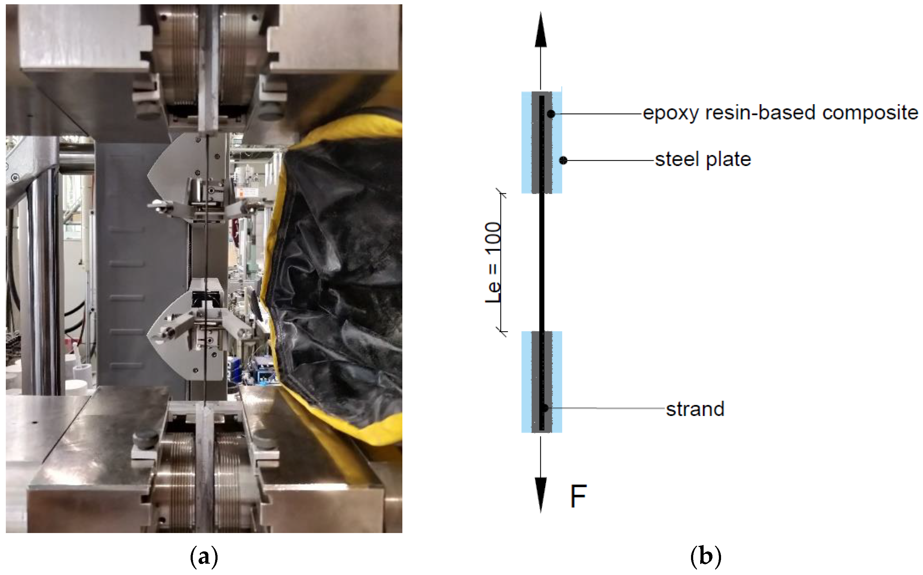
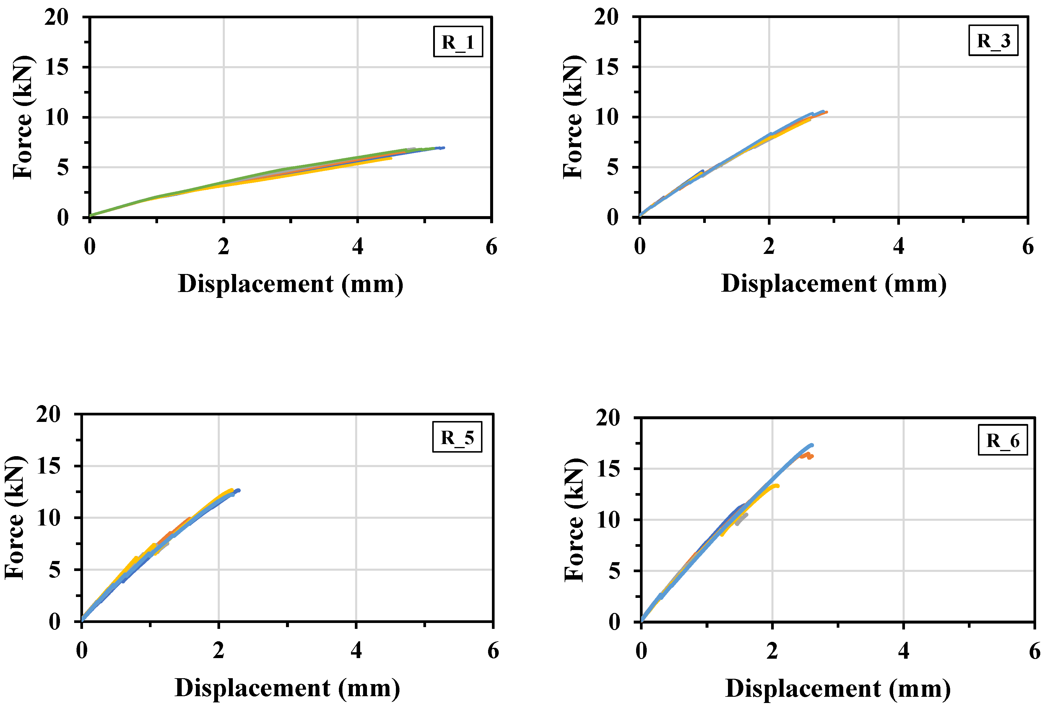
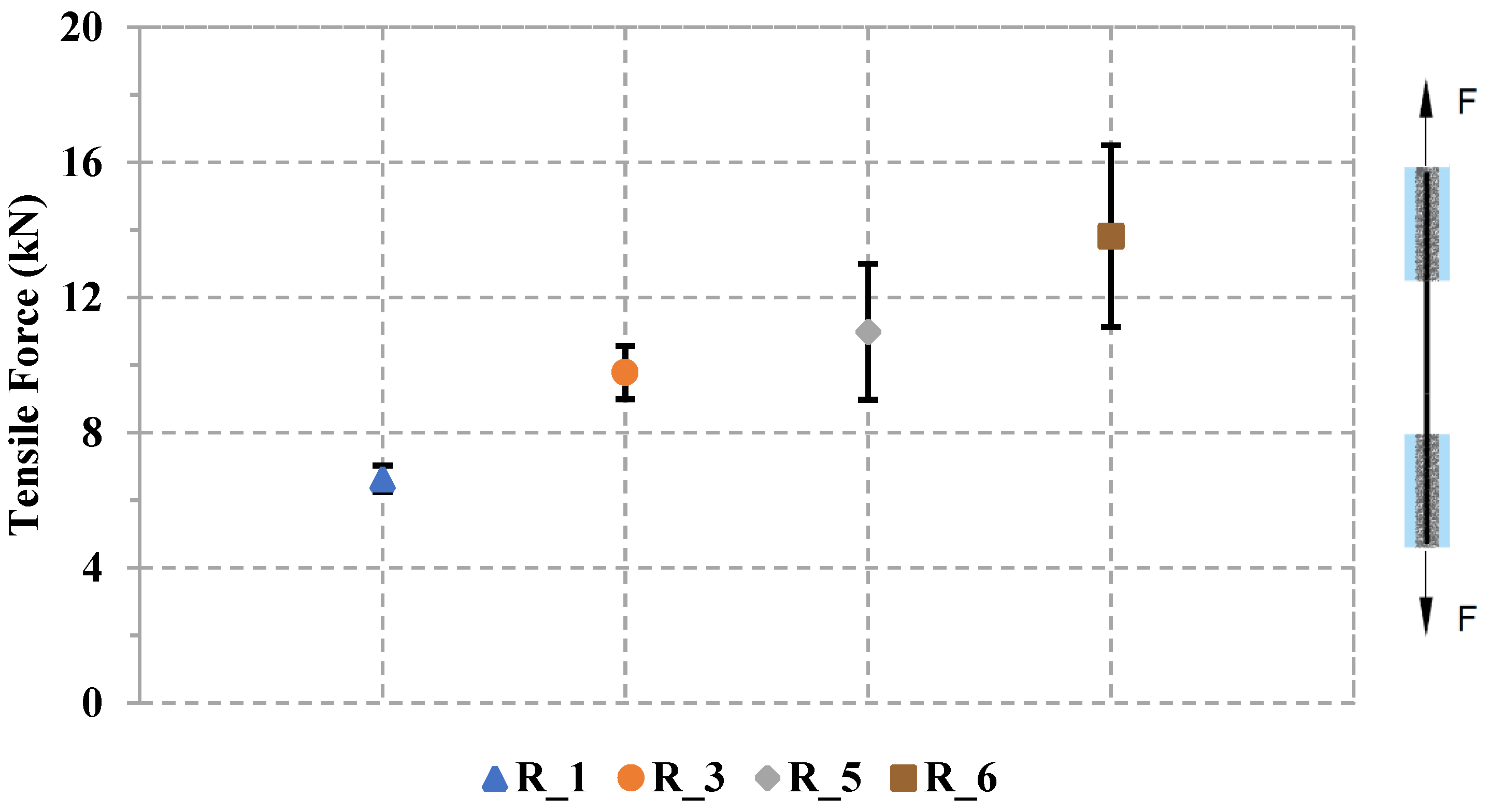
It can be concluded from the tensile tests carried out on the straight yarns that increasing the number of rovings in the strands substantially enhances the ultimate load capacity of the strands. The R_1 specimen with a single roving displayed a peak tensile force of 6.6 kN. The R_3 specimen measured 9.7 kN, the R_5 specimen reached 10.9 kN, and the R_6 specimen achieved the highest tensile force at 13.8 kN. The R_6 specimen with six rovings in the strand shows a 109% increase compared to the R_1 specimen with a single roving. This increase in the tensile force can be attributed to the increased cross-sectional area of the strand, load-sharing capacity of strand, and a synergistic roving effect.
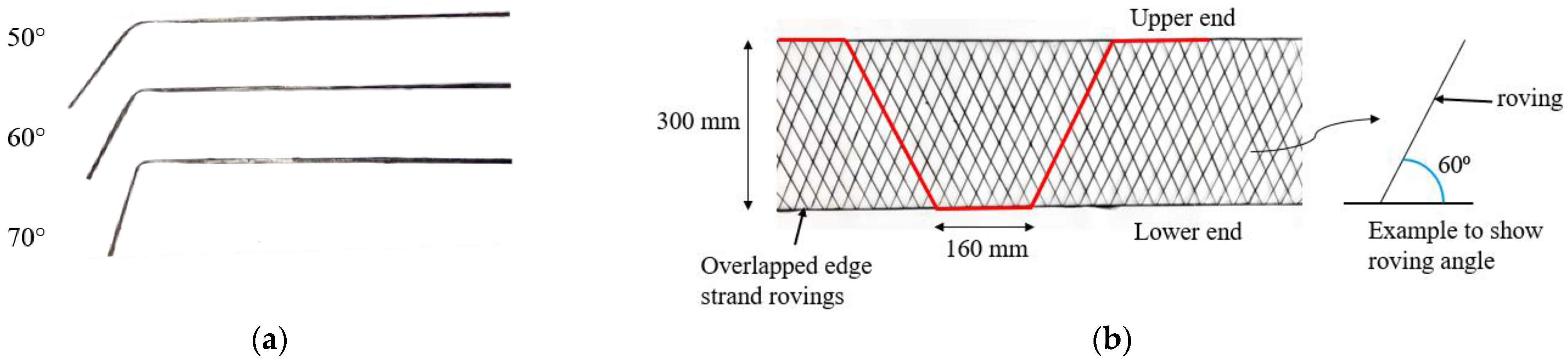
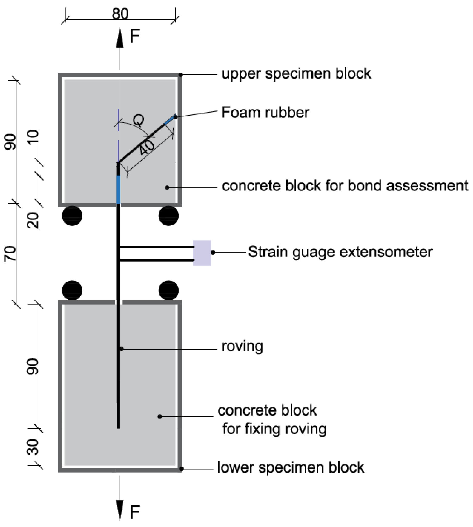
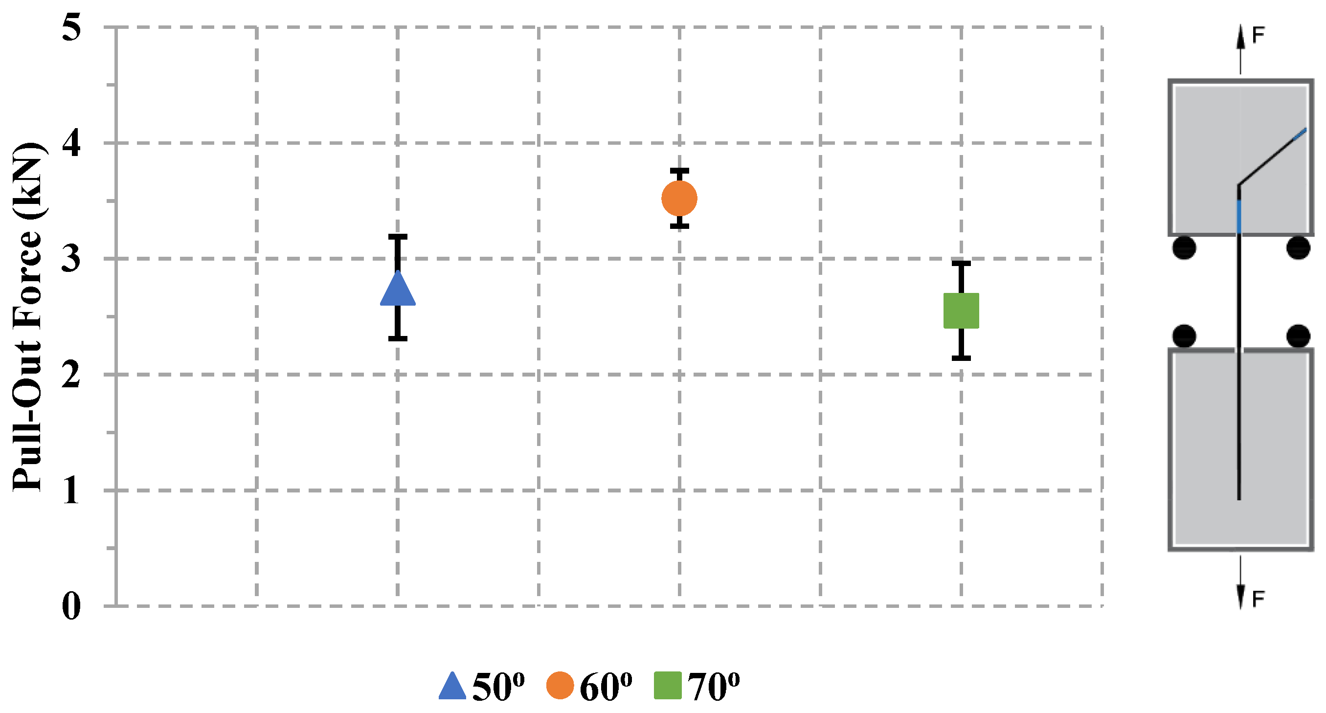
The YPO test examined the effect of textile roving inclination on the maximum pull-out load in the concrete. The test results showed that the 50° roving exhibited an average pull-out force of 2.7 kN, whereas the 60° roving showed a higher pull-out force of 3.5 kN. However, as the angle of the roving increased to 70°, the pull-out force decreased to 2.5 kN. The maximum pull-out force increased by 29.6% when the roving angle increased from 50° to 60°, attributed to increased friction and improved interlocking. However, a further increase in roving angle from 60° to 70° led to a 40% decrease in maximum pull-out force, which can be attributed to a stress concentration. Overall, the YPO testing setup suggests that a roving angle of 60° provided higher strength and can be considered as an optimized angle.
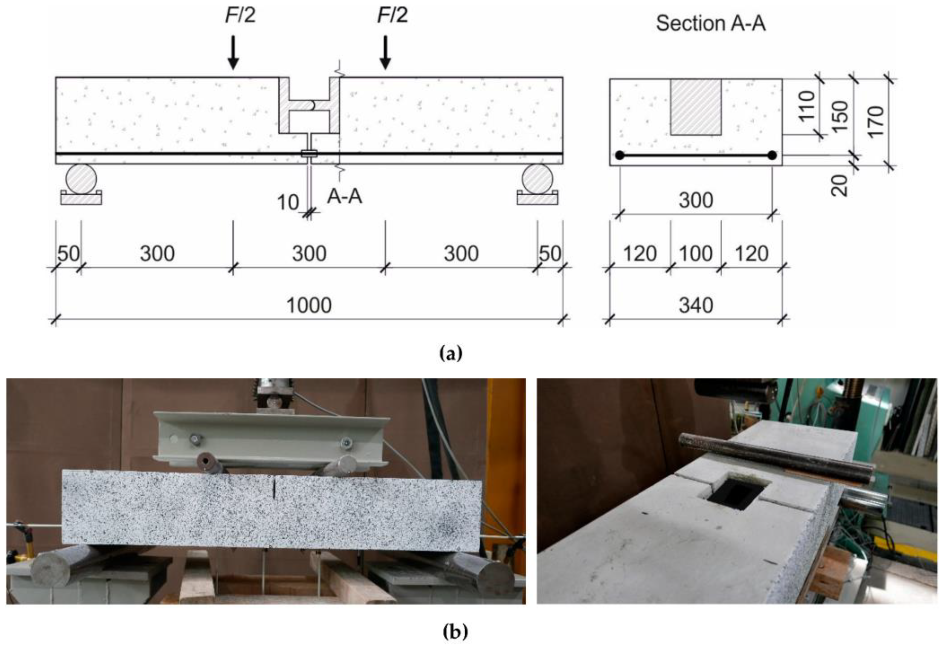
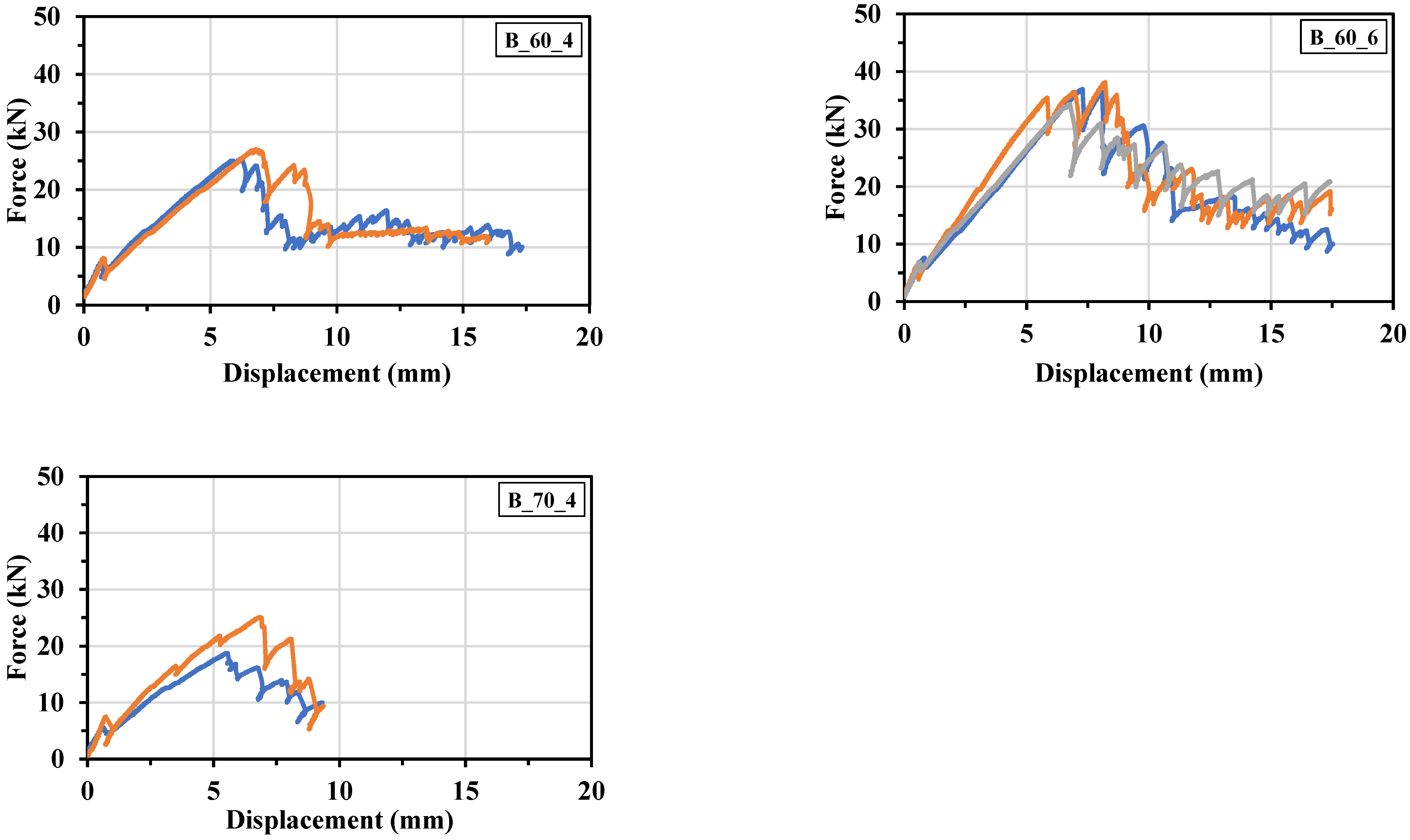
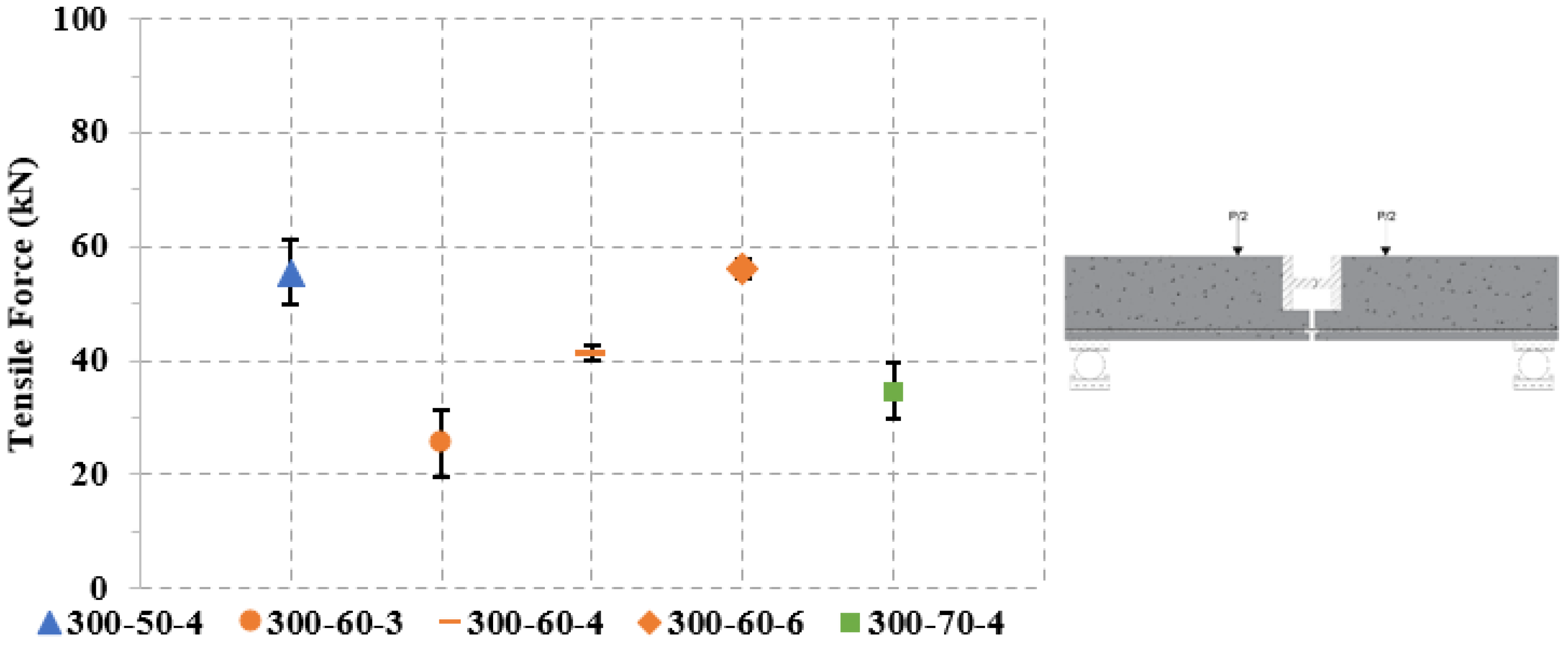
The four-point bending test focused on determining the total tensile capacity of 2D NetzGT reinforcement. It can be concluded from the test results that increasing the number of overlapped edge rovings increased the maximum tensile capacity of the reinforcement. For example, in the B-60-3 specimen, the maximum tensile force reached 25.4 kN. Subsequently, this force increased substantially by 62% to 41.3 kN in the B-60-4 specimen. Furthermore, the tensile force continued to rise, reaching 56.1 kN in the B-60-6 specimen. This represented a substantial increase of 120% compared to B-60-3 and a 35% increase from the B-60-4 specimen. This trend highlights the positive correlation between the number of edge-overlapped rovings and the maximum tensile force. It was also concluded that keeping the same number of edge-overlapped rovings in the strand, the increased longitudinal alignment of the textile roving led to greater activation of the roving, thereby enhancing the tensile capacity of the NetzGT reinforcement.
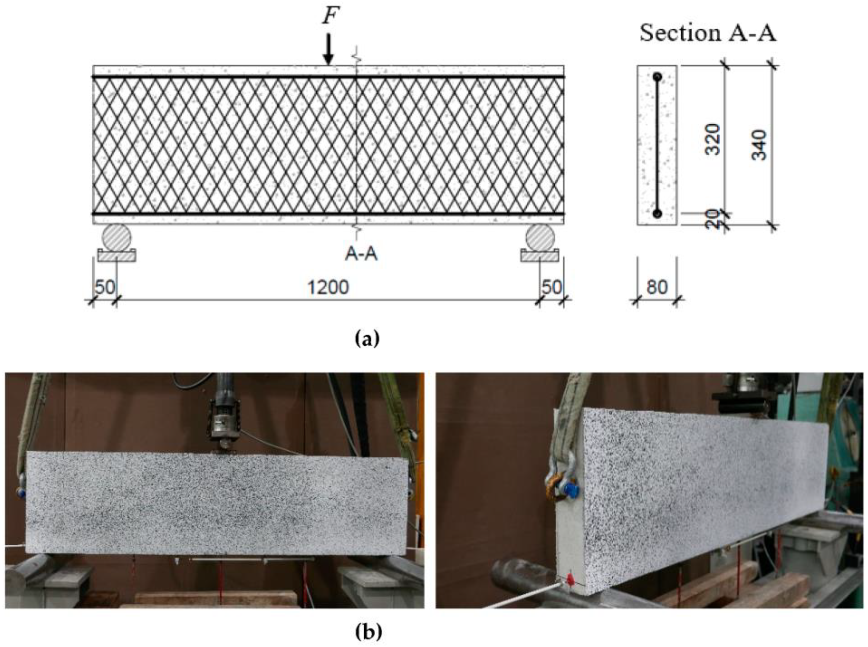
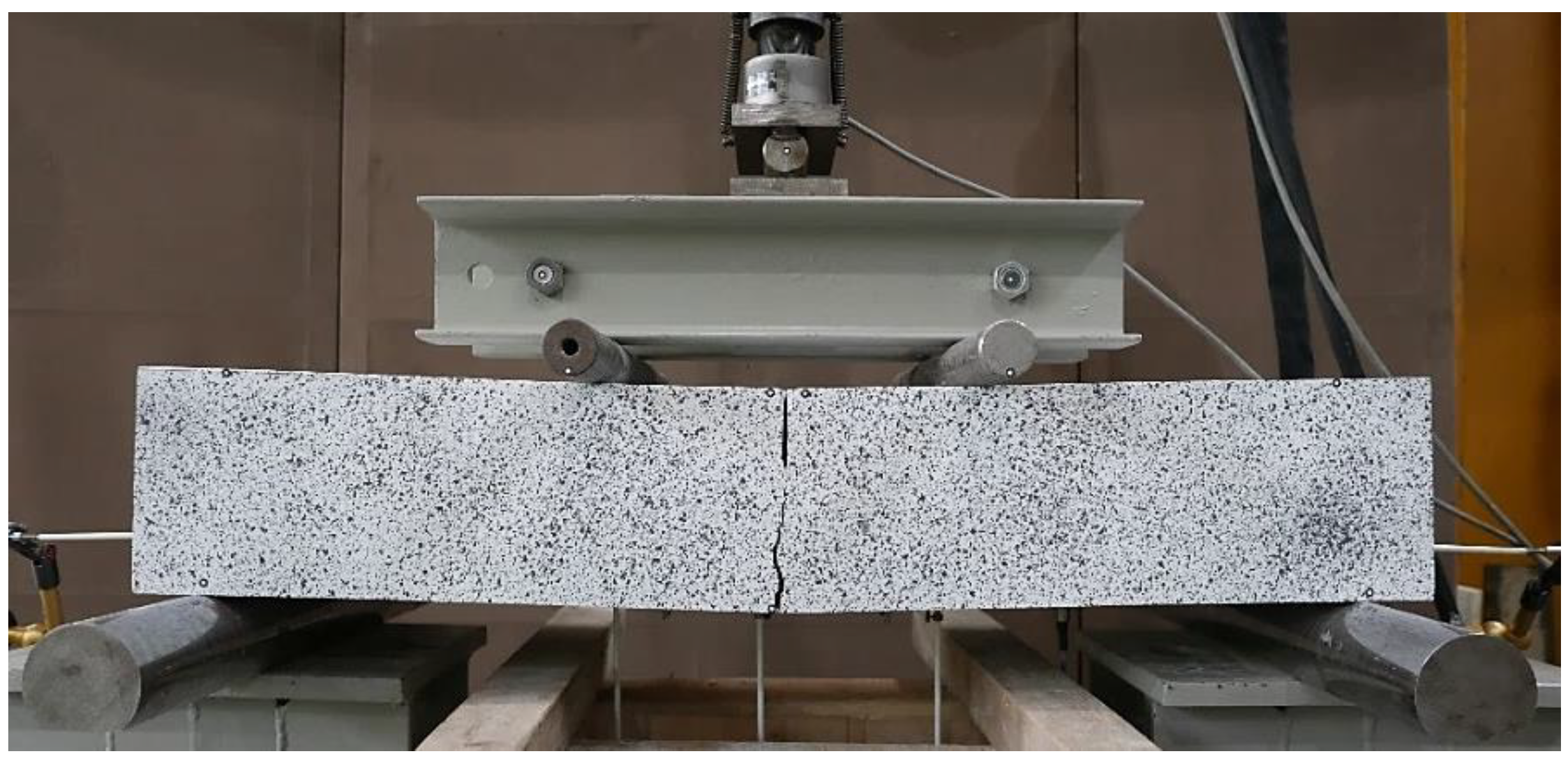
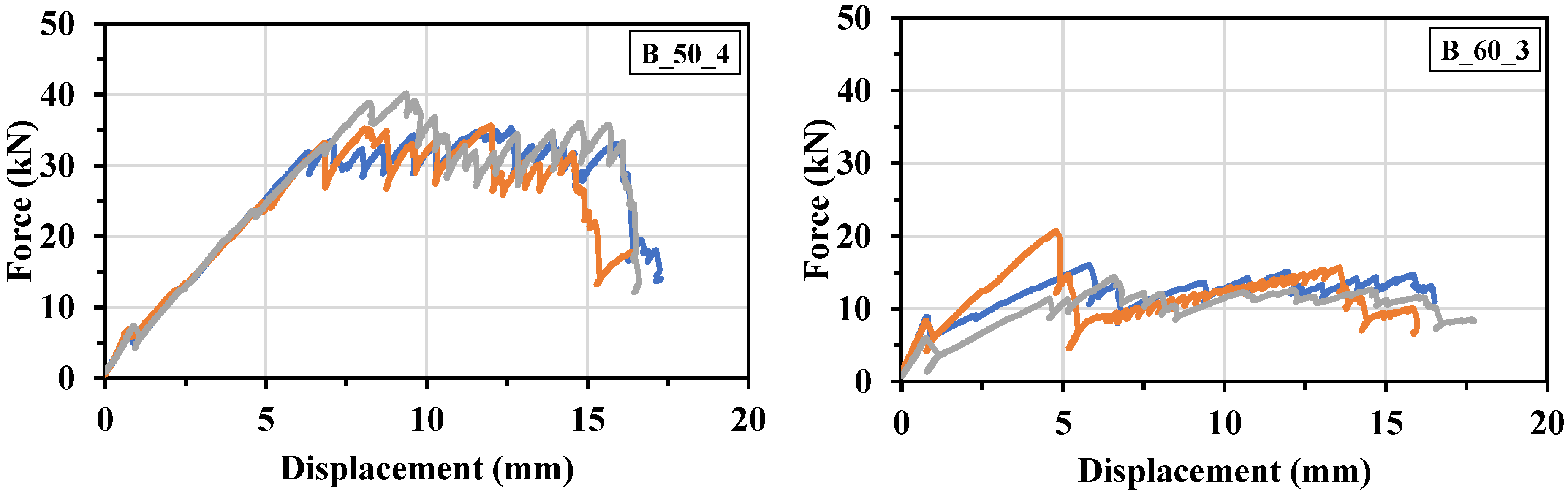
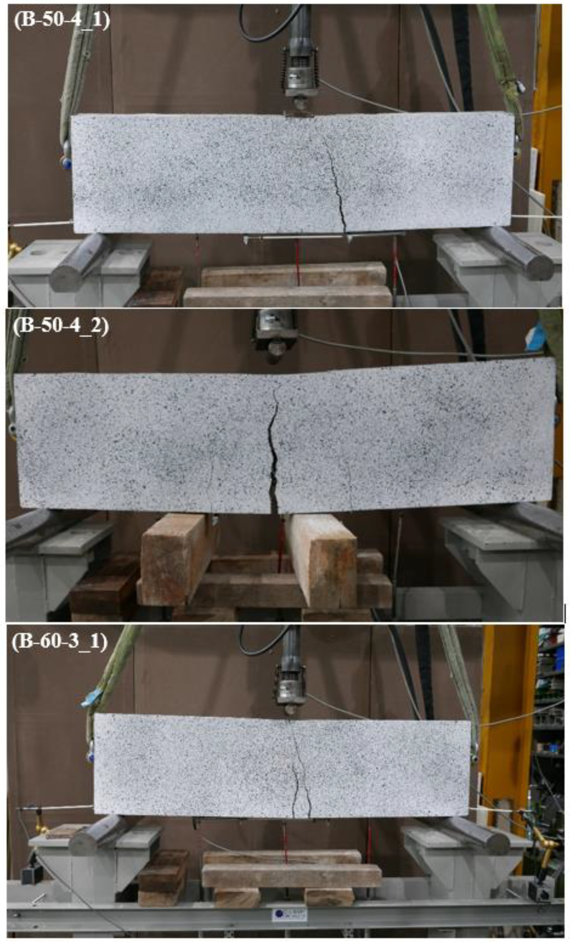
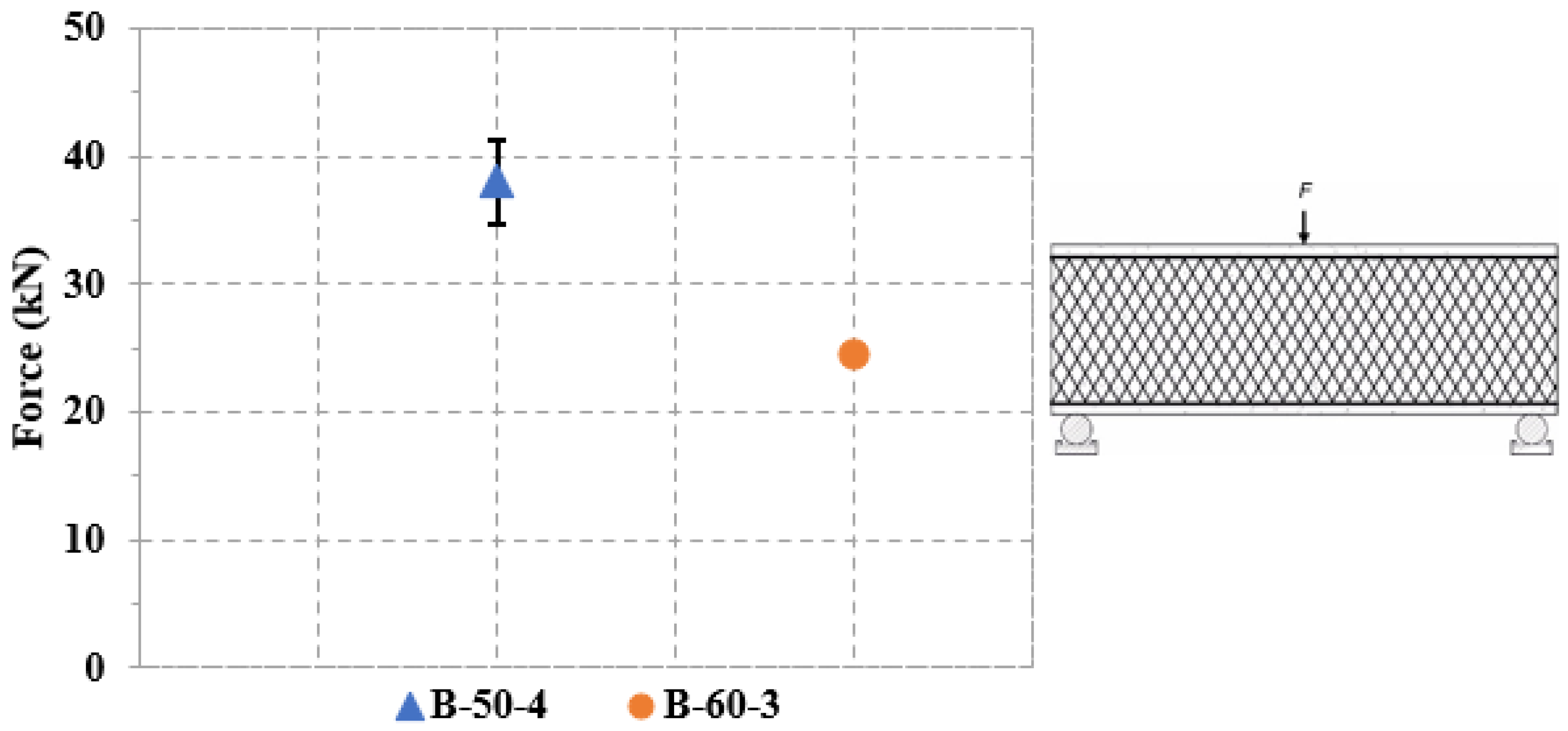
In the three-point bending test, specimens with a 50° roving angle, such as B-50-4, showed a significantly higher maximum failure load with an average force of 38.5 kN, a 56% increase compared to the 60° roving specimen such as B-60-3. The higher number of overlapped rovings in the 50° specimens likely contributed to this increase. However, to draw confident conclusions, future studies should examine one factor at a time. It is suggested from the shear test results that one potential approach could involve introducing longitudinal reinforcement to enhance the bending capacity of the beam and intentionally induce shear failure to study the effect of vertically placed 2D NetzGT reinforcement.

Author Contributions

N.U.R.: Conceptualization, Methodology, Data curation, Investigation, Supervision, Validation, Writing—Original draft preparation. M.S.: Conceptualization, Methodology, Data curation, Investigation, Supervision, Validation, Writing—Review and Editing. H.M.: Conceptualization, Methodology, Supervision, Validation, Writing—Review and Editing. P.P.: Resources, Validation, Writing—Review and Editing. B.B.: Resources, Supervision, Funding acquisition, Project administration. L.H.: Resources, Supervision, Validation, Writing—Review and Editing. C.C.: Resources, Supervision, Funding acquisition, Project administration. S.M.: Conceptualization, Supervision, Funding acquisition, Project administration. All authors have read and agreed to the published version of the manuscript.

Funding

The IGF research project 21556 BR of the Forschungsvereinigung Forschungskuratorium Textil e. V. is funded through the AiF within the program for supporting the Industriellen Gemeinschaftsforschung (IGF) from funds of the Federal Ministry for Economic Affairs and Climate Action on the basis of a decision by the German Bundestag.

Data Availability Statement

Not applicable.

Acknowledgments

The authors are thankful to the Otto Mohr Laboratory (OML) team for producing testing specimens and conducting tests. Special thanks to Rene Wallschläger and Michael Liebe for their valuable input to this work.

Conflicts of Interest

The authors declare that they have no conflict of interest associated with the work presented in this paper.

References

  1. Shan, Y.; Zhou, Y.; Meng, J.; Mi, Z.; Liu, J.; Guan, D. Peak cement-related CO2 emissions and the changes in drivers in China. J. Ind. Ecol. 2019, 23, 959–971. [Google Scholar] [CrossRef]
  2. Barcelo, L.; Kline, J.; Walenta, G.; Gartner, E. Cement and carbon emissions. Mater. Struct. 2014, 47, 1055–1065. [Google Scholar] [CrossRef]
  3. Andrew, R.M. Global CO2 emissions from cement production. Earth Syst. Sci. Data 2018, 10, 195–217. [Google Scholar] [CrossRef]
  4. Umweltfreundliche Betonbauten?—Concrete E-Learning Platform|IBK, ETH Zürich. Available online: https://concrete.ethz.ch/blog/umweltfreundliche-betonbauten/ (accessed on 22 September 2023).
  5. Cao, Z.; Masanet, E.; Tiwari, A.; Akolawala, S. Decarbonizing Concrete: Deep decarbonization pathways for the cement and concrete cycle in the United States, India, and China. Ind. Sustain. Anal. Lab Clim. Found. 2021. [Google Scholar]
  6. Beckmann, B.; Bielak, J.; Bosbach, S.; Scheerer, S.; Schmidt, C.; Hegger, J.; Curbach, M. Collaborative research on carbon reinforced concrete structures in the CRC/TRR 280 project. Civ. Eng. Des. 2021, 3, 99–109. [Google Scholar] [CrossRef]
  7. Raju, A.; Shanmugaraja, M. Recent researches in fiber reinforced composite materials: A review. Mater. Today Proc. 2021, 46, 9291–9296. [Google Scholar] [CrossRef]
  8. MCurbach, M.; Jesse, F. High-performance textile-reinforced concrete. Struct. Eng. Int. 1999, 9, 289–291. [Google Scholar] [CrossRef]
  9. Penzel, P.; May, M.; Hahn, L.; Scheerer, S.; Michler, H.; Butler, M.; Waldmann, M.; Curbach, M.; Cherif, C.; Mechtcherine, V. Bond Modification of Carbon Rovings through Profiling. Materials 2022, 15, 5581. [Google Scholar] [CrossRef]
  10. Abdkader, A.; Penzel, P.; Friese, D.; Overberg, M.; Hahn, L.; Butler, M.; Mechtcherine, V.; Cherif, C. Improved Tensile and Bond Properties through Novel Rod Constructions Based on the Braiding Technique for Non-Metallic Concrete Reinforcements. Materials 2023, 16, 2459. [Google Scholar] [CrossRef]
  11. Hegger, J.; Curbach, M.; Stark, A.; Wilhelm, S.; Farwig, K. Innovative design concepts: Application of textile reinforced concrete to shell structures. Struct. Concr. 2018, 19, 637–646. [Google Scholar] [CrossRef]
  12. Schladitz, F.; Lieboldt, M. Carbonbeton–Was ist schon möglich? Beton 2019, 69, 156–161. [Google Scholar]
  13. Silva, R.M.d.C.; Silva, F.d.A. Carbon textile reinforced concrete: Materials and structural analysis. Mater. Struct. 2020, 53, 17. [Google Scholar] [CrossRef]
  14. Tietze, M.; Kirmse, S.; Kahnt, A.; Schladitz, F.; Curbach, M. The ecological and economic advantages of carbon reinforced concrete—Using the C3 result house CUBE especially the BOX value chain as an example. Civ. Eng. Des. 2022, 4, 79–88. [Google Scholar] [CrossRef]
  15. Development of Carbon-Reinforced Hollow Core Slab—Zenodo. Available online: https://zenodo.org/record/8116760 (accessed on 11 August 2023).
  16. Mechtcherine, V. Novel cement-based composites for the strengthening and repair of concrete structures. Constr. Build Mater. 2013, 41, 365–373. [Google Scholar] [CrossRef]
  17. Wagner, J.; Würgau, C.; Schumann, A.; Schütze, E.; Ehlig, D.; Nietner, L.; Curbach, M. Strengthening of Reinforced Concrete Structures with Carbon Reinforced Concrete—Possibilities and Challenges. CivilEng 2022, 3, 400–426. [Google Scholar] [CrossRef]
  18. Friese, D.; Scheurer, m.; Hahn, L.; Gries, T.; Cherif, C. Textile reinforcement structures for concrete construction applications––A review. J. Compos. Mater. 2022, 56, 4041–4064. [Google Scholar] [CrossRef]
  19. Let’s Get CUBE—Carbon-Concrete.Org. Available online: https://carbon-concrete.org/lets-get-cube/ (accessed on 9 November 2022).
  20. Michler, H. Lattice Girder for Concrete Structures—Patent Application 102016124226, Germany 2016. Available online: https://patents.google.com/patent/DE102016124226A1/en (accessed on 9 November 2022).
  21. Kromoser, B.; Preinstorfer, P.; Kollegger, J. Building lightweight structures with carbon-fiber-reinforced polymer-reinforced ultra-high-performance concrete: Research approach, construction materials, and conceptual design of three building components. Struct. Concr. 2019, 20, 730–744. [Google Scholar] [CrossRef]
  22. Carbon Fibre-Reinforced Concrete Offers Innovative Solutions for Civil Engineering|TUCaktuell|TU Chemnitz. Available online: https://www.tu-chemnitz.de/tu/pressestelle/aktuell/7105/en (accessed on 7 July 2023).
  23. Rempel, S.; Kulas, C.; Will, N.; Bielak, J. Extremely Light and Slender Precast-Bridge Made out of Textile-Reinforced-Concrete. In High Tech Concrete: Where Technology and Engineering Meet; Hordijk, D., Luković, M., Eds.; Springer: Cham, Switzerland, 2017. [Google Scholar] [CrossRef]
  24. Michler, H. Segmentbrücke aus textilbewehrtem Beton–Rottachsteg Kempten im Allgäu. Beton-Und Stahlbetonbau 2013, 108, 325–334. [Google Scholar] [CrossRef]
  25. Curbach, M.; Graf, W.; Jesse, D.; Sickert, J.; Weiland, S. Segmentbrücke aus textilbewehrtem Beton: Konstruktion, Fertigung, numerische Berechnung. Beton-Und Stahlbetonbau 2007, 102, 342–352. [Google Scholar] [CrossRef]
  26. Carbon composite pedestrian bridge installed in Madrid. Reinf. Plast. 2011, 55, 43–44. [CrossRef]
  27. V4.2 Vorgespannter Carbonbeton für Straßenbrücken und Flächentragwerke—Carbon Concrete Composite e.V. Available online: https://www.bauen-neu-denken.de/vorhaben/v4-2-vorgespannter-carbonbeton-fuer-strassenbruecken-und-flaechentragwerke/ (accessed on 7 July 2023).
  28. Schumann, A.; May, S.; Curbach, M. Design and testing of various ceiling elements made of carbon reinforced concrete. Proceedings 2018, 2, 543. [Google Scholar]
  29. Schumann, A.; Michler, H.; Schladitz, F.; Curbach, M. Parking slabs made of carbon reinforced concrete. Struct. Concr. 2018, 19, 647–655. [Google Scholar] [CrossRef]
  30. Curbach, M.; Weiland, S.; Michler, H. Le béton à armature textile. Text. J. 2008, 125, 59–69. [Google Scholar]
  31. Scholzen, A.; Chudoba, R.; Hegger, J. Thin walled shell structure made of textile reinforced concrete. Struct. Concr. 2014, 16, 106–114. [Google Scholar] [CrossRef]
  32. Das Unternehmen–Informbeton. Available online: http://www.informbeton.de/das-unternehmen.html (accessed on 11 August 2023).
  33. CHT Group—Sustainable Specialty Chemicals: CHT Group. Available online: https://www.cht.com/en/ (accessed on 11 August 2023).
  34. Hahn, L.; Rittner, S.; Bauer, C.; Cherif, C. Development of alternative bondings for the production of stitch-free non-crimp fabrics made of multiple carbon fiber heavy tows for construction industry. J. Ind. Text. 2018, 48, 660–681. [Google Scholar] [CrossRef]
  35. Sikadur®-30|Structural Adhesives. Available online: https://mng.sika.com/en/construction/structural-strengthening/structural-adhesives/sikadur-30.html (accessed on 21 July 2023).
  36. Schneider, K.; Michel, A.; Liebscher, M.; Terreri, l.; Hempel, S.; Mechtcherine, V. Mineral-impregnated carbon fibre reinforcement for high temperature resistance of thin-walled concrete structures. Cem. Concr. Compos. 2019, 97, 68–77. [Google Scholar] [CrossRef]
  37. Carvalho, E.P.; Ferreira, E.G.; da Cunha, J.C.; Rodrigues, C.d.S.; Maia, N.d.S. Experimental investigation of steel-concrete bond for thin reinforcing bars. Lat. Am. J. Solids Struct. 2017, 14, 1932–1951. [Google Scholar] [CrossRef]
  38. Quadflieg, T.; Stolyarov, O.; Gries, T. Influence of the fabric construction parameters and roving type on the tensile property retention of high-performance rovings in warp-knitted reinforced fabrics and cement-based composites. J. Ind. Text. 2017, 47, 453–471. [Google Scholar] [CrossRef]
  39. Hartig, J.; Häußler-Combe, U.; Schicktanz, K. Influence of bond properties on the tensile behaviour of Textile Reinforced Concrete. Cem. Concr. Compos. 2008, 30, 898–906. [Google Scholar] [CrossRef]
Figure 1. World’s first building constructed with carbon concrete (Photo: Stefan Mueller).
Buildings 13 02552 g001
Figure 2. (a) Single textile roving with 50°, 60°, and 70° roving angle; (b) 2D NetzGT reinforcement for beam pull-out and shear test experiments (top view and side view).
Buildings 13 02552 g002
Figure 3. Strand prepared to be tested under tension (a); Schematic test setup for tension test on roving and strands (b). Unit is mm.
Buildings 13 02552 g003
Figure 4. Schematic test setup for YPO test. The angle Q in the figure is the angle of roving (50°, 60°, and 70°). All dimensions are in mm.
Buildings 13 02552 g004
Figure 5. (a) Schematic test setup for tension test on 2D NetzGT reinforcement; (b) Visualized beam specimen. All dimensions are in mm.
Buildings 13 02552 g005
Figure 6. (a) Schematic test setup for the three-point bending test. (b) Visualized beam subjected to three-point bending test. All dimensions are in mm.
Buildings 13 02552 g006
Figure 7. Force-displacement curves for single and multiple rovings tested in tension.
Buildings 13 02552 g007
Figure 8. Average maximum tensile force for a single roving and strands.
Buildings 13 02552 g008
Figure 9. Pull-out forces for different angles of rovings embedded in matrix.
Buildings 13 02552 g009
Figure 10. Beam subjected to four-point bending test according to RILEM RC5 with some specific modifications. Beam dimensions are L × B × D = 1000 mm × 340 mm × 170 mm.
Buildings 13 02552 g010
Figure 11. Force–displacement curves for strands with varying edge-overlapped rovings and angle of the rovings.
Buildings 13 02552 g011aBuildings 13 02552 g011b
Figure 12. Maximum tensile force for strands with varying overlapped edge rovings and angle of rovings.
Buildings 13 02552 g012
Figure 13. Beams subjected to a three-point bending test. Beam dimensions are L × B × D = 1300 mm × 80 mm × 340 mm.
Buildings 13 02552 g013
Figure 14. Maximum force resulted from three-point bending test.
Buildings 13 02552 g014
Table 1. Composition of concrete mix C30/37.
Component/ContentCEM II/A-LL 52.5 RLimestone Powder Compact IIISand 0/2Coarse Aggregate 2/8WaterSuperplasticizer Glenium ACE 40 (FM)
(kg/m3)270155800900190approx. 4
Table 2. Overview of different overlapped rovings.
FoldingThe Surface of Single and Multiple RovingsDiameter (mm)
1 × 3200texBuildings 13 02552 i0013
3 × 3200texBuildings 13 02552 i0024.5
5 × 3200texBuildings 13 02552 i0035.1
6 × 3200texBuildings 13 02552 i0045.3
Table 3. Test program for the four-point bending test.
SeriesB-50-4B-60-3B-60-4B-60-6B-70-4
Number of Specimens33232
Table 4. Test program for three-point bending test.
SeriesB-50-4B-60-3
Number of Specimens21
Table 5. Strand tensile capacities manufactured with different numbers of rovings.
Specimen IDNumber of SpecimensArea of Carbon Strand (mm2)Maximum Tension Force (kN)Standard Deviation
R_151.86.640.39
R_355.49.780.79
R_559.010.992.01
R_6510.813.822.68
Table 6. Summary of the tension test on 2D NetzGT reinforcement.
Specimen IDNumber of SpecimensNumber of RovingsDiameter of Roving (mm)Maximum Tensile Force in 2D NetzGT (kN)Standard Deviation
B-50-4344.955.45.7
B-60-3334.525.45.9
B-60-4244.941.31.2
B-60-6365.356.11.7
B-70-4244.934.64.9
Table 7. Three-point bending test results.
Specimen IDNumber of RovingsDiameter of Roving (mm)First Crack Load (kN)Maximum Load (kN)Maximum Crack Width (mm)
B-50-444.916.541.813.9
B-50-444.917.335.115.4
B-60-334.515.724.615.4
Disclaimer/Publisher’s Note: The statements, opinions and data contained in all publications are solely those of the individual author(s) and contributor(s) and not of MDPI and/or the editor(s). MDPI and/or the editor(s) disclaim responsibility for any injury to people or property resulting from any ideas, methods, instructions or products referred to in the content.

