

Modular Construction of Topological Interlocking Blocks—An Algebraic Approach for Resource-Efficient Carbon-Reinforced Concrete Structures
 , , , , and
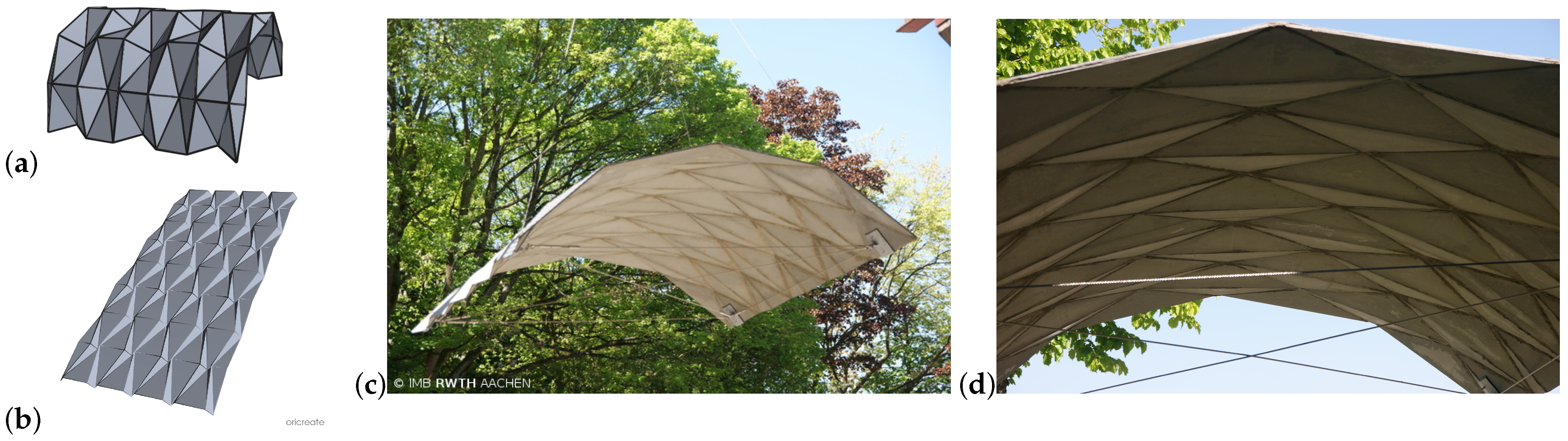
Abstract
:1. Introduction
1.1. Carbon-Reinforced Concrete
1.2. Algebra in Civil Engineering
1.3. Interlocking
1.3.1. Analogy and Explanation
1.3.2. Mathematical Description
1.3.3. Using Topological Interlocking in the Design of Carbon Concrete Components
2. Methods
2.1. Convex Hull
2.2. Topological Interlocking
- is an assembly, that is, any two blocks can only intersect at their boundaries;
- Any finite subset of blocks indexed by cannot be moved using continuous motions (interlocking property).
2.3. Infinitesimal Criterion for a Topological Interlocking
3. Results
3.1. Construction of the Blocks
3.2. Designing Topological Interlocking Blocks
3.2.1. Designing Topological Interlocking Blocks by Attaching 3-Prisms
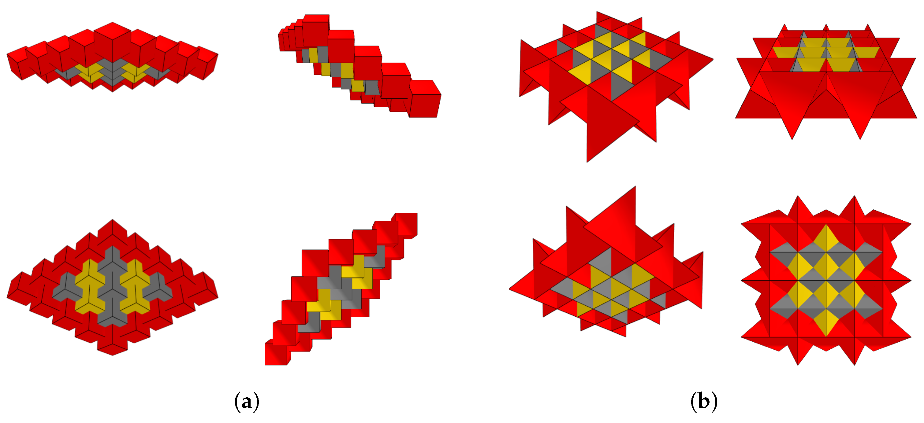
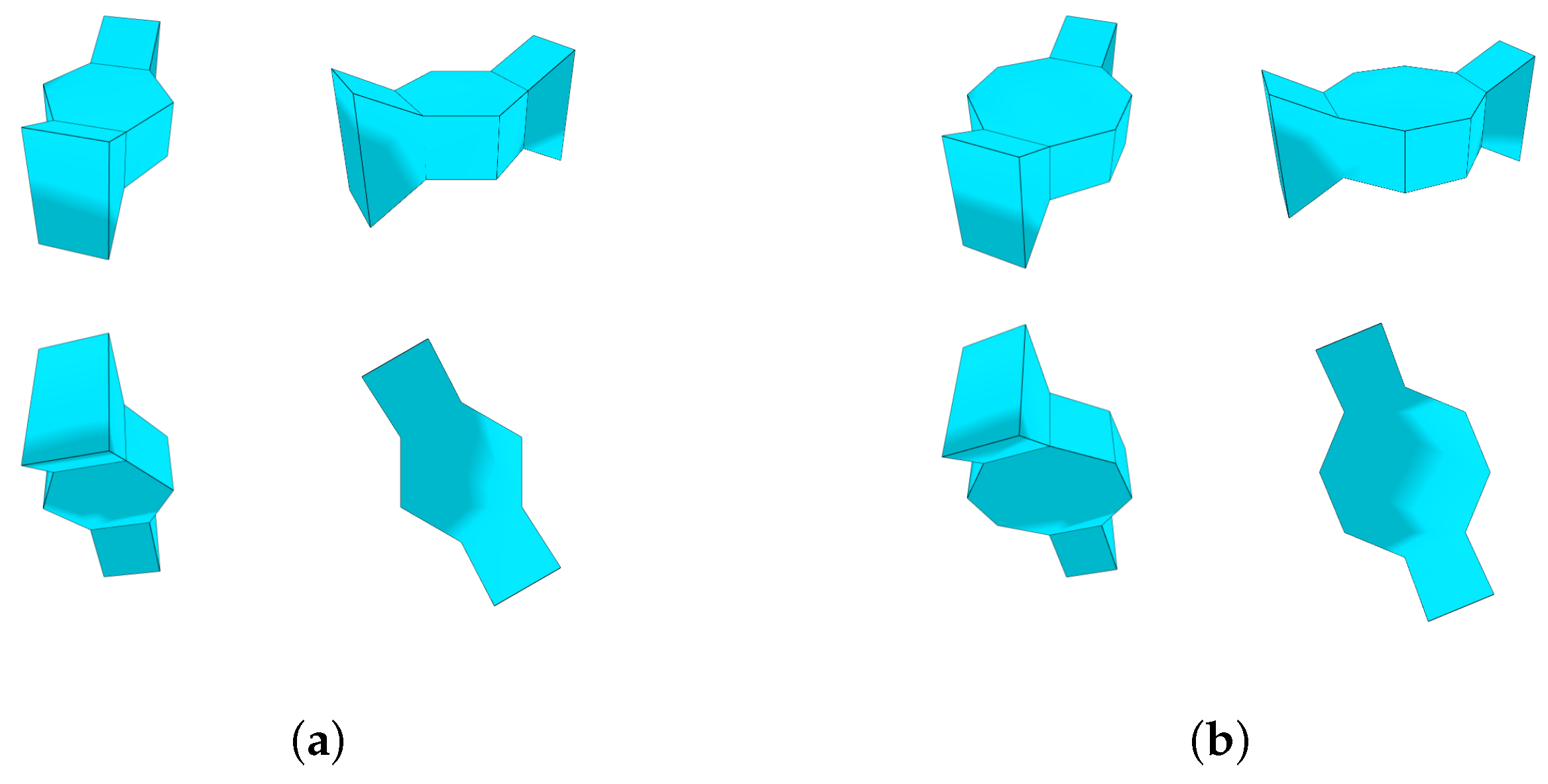
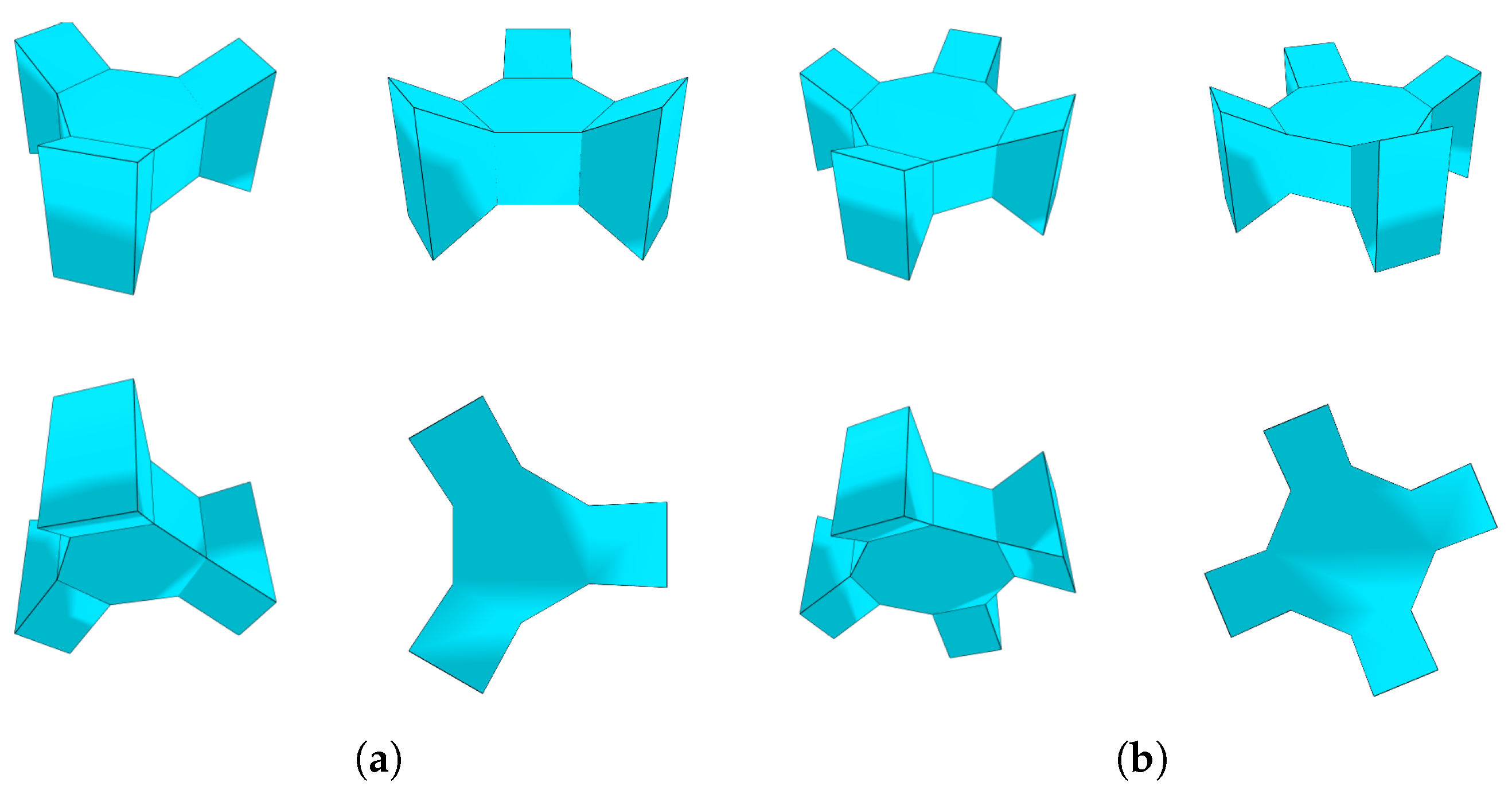
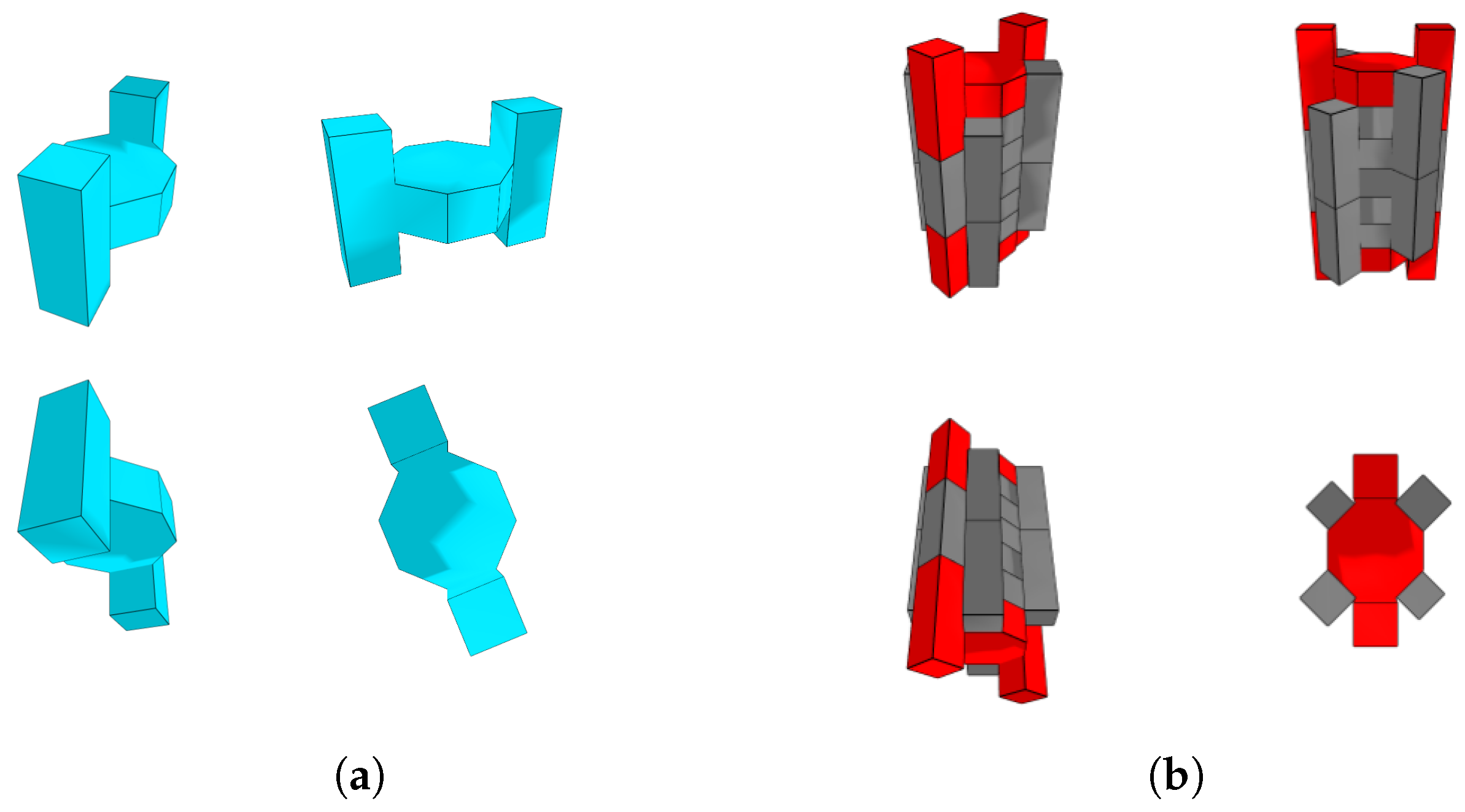
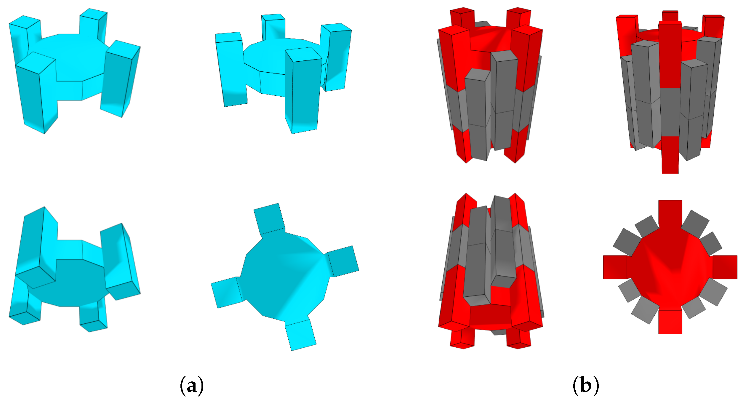
- Merge three 3-prisms so that the resulting convex body is given by(see Figure 9b). This block shall be referred to as 3-hat.
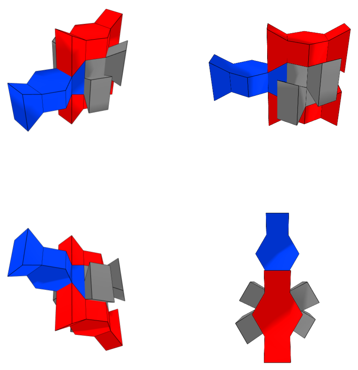
- For , merge S and a copy of the above block along the facet and the facet of 3-hat given bysuch that no facet of the attached 3-hat is contained in the plane spanned by one of the regular n-gons that is a facet of The resulting block is called n-candy.
3.2.2. Designing Topological Interlocking Blocks by Attaching Cubes
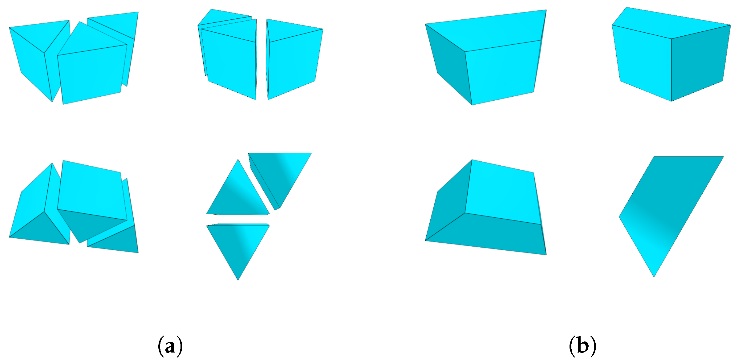
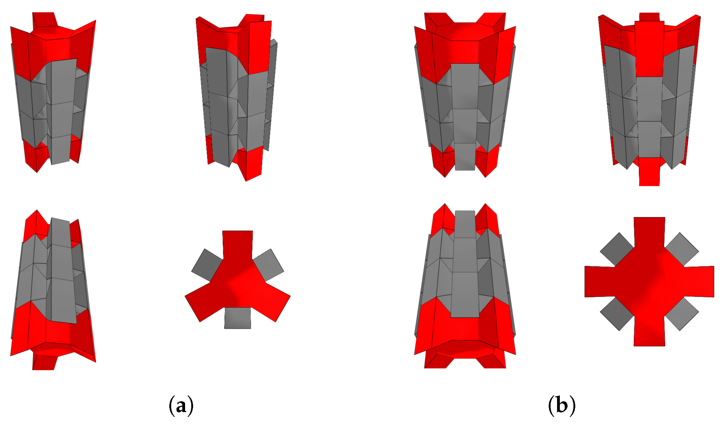
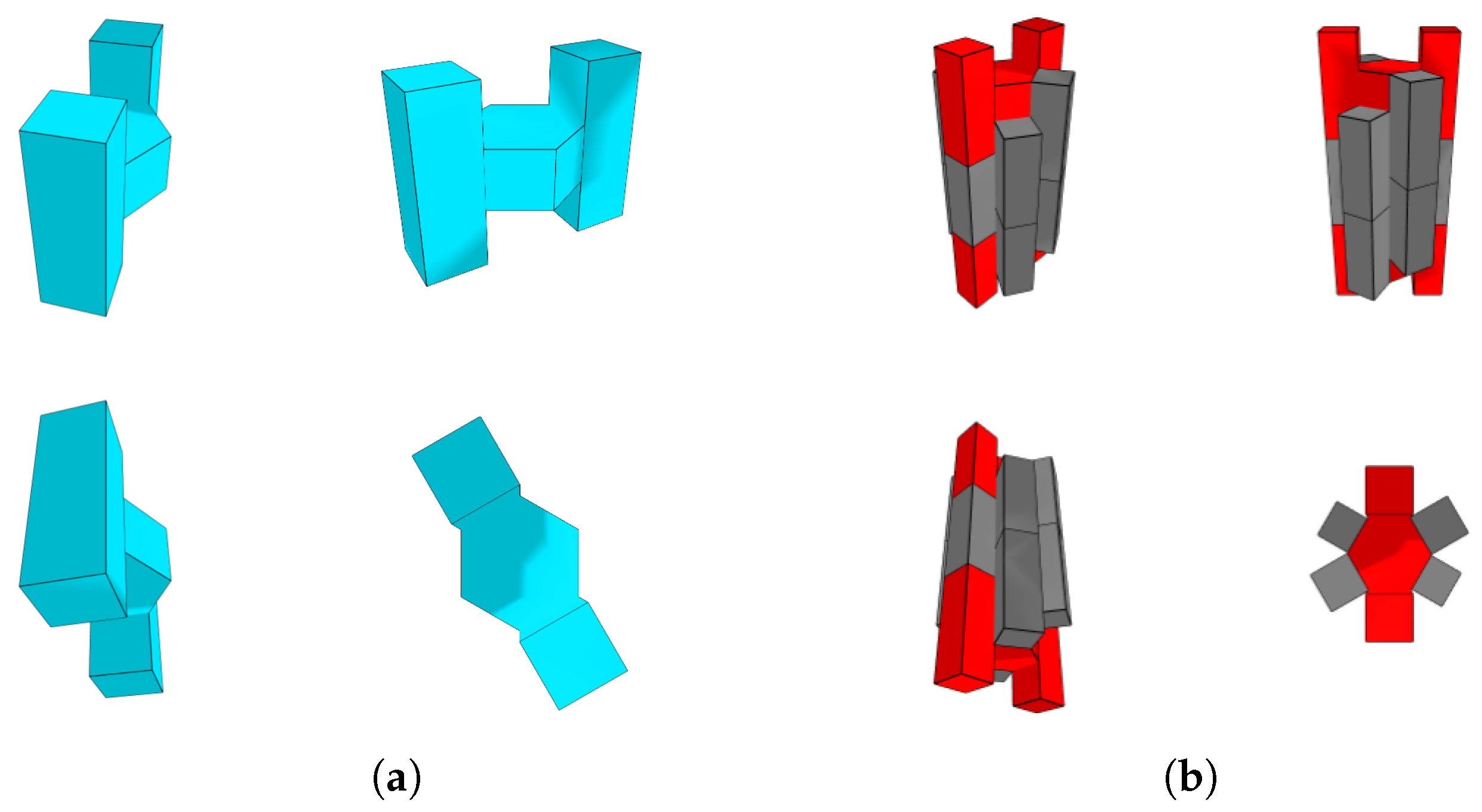
- Merge three cubes so that the resulting convex body is a cuboid with edge lengths 3 and 1. Such a convex body can be constructed by the following convex hull:This block shall be referred to as 4-hat.
- As seen above, the n-prism S can be merged with a copy of the above block for along the facet and the subfacet of 4-hat given bysuch that no facet of the 4-hat is contained in a plane spanned by one of the regular n-gons that is a facet of
3.3. Proving the Interlocking Property
- Contact points, i.e., zero-dimensional intersections, that result from the intersection of two non-parallel edges of two different blocks;
- Contact facets (given as the convex set of a finite number of contact points), i.e., two-dimensional intersections, that result from the intersection of two facets of two different blocks.
- For a contact point of two non-parallel edges, the necessary plane for the constraint is spanned by the corresponding two edges;
- For each contact point of a contact facet, a constraint is derived by considering the plane spanned by the corresponding contact facet.
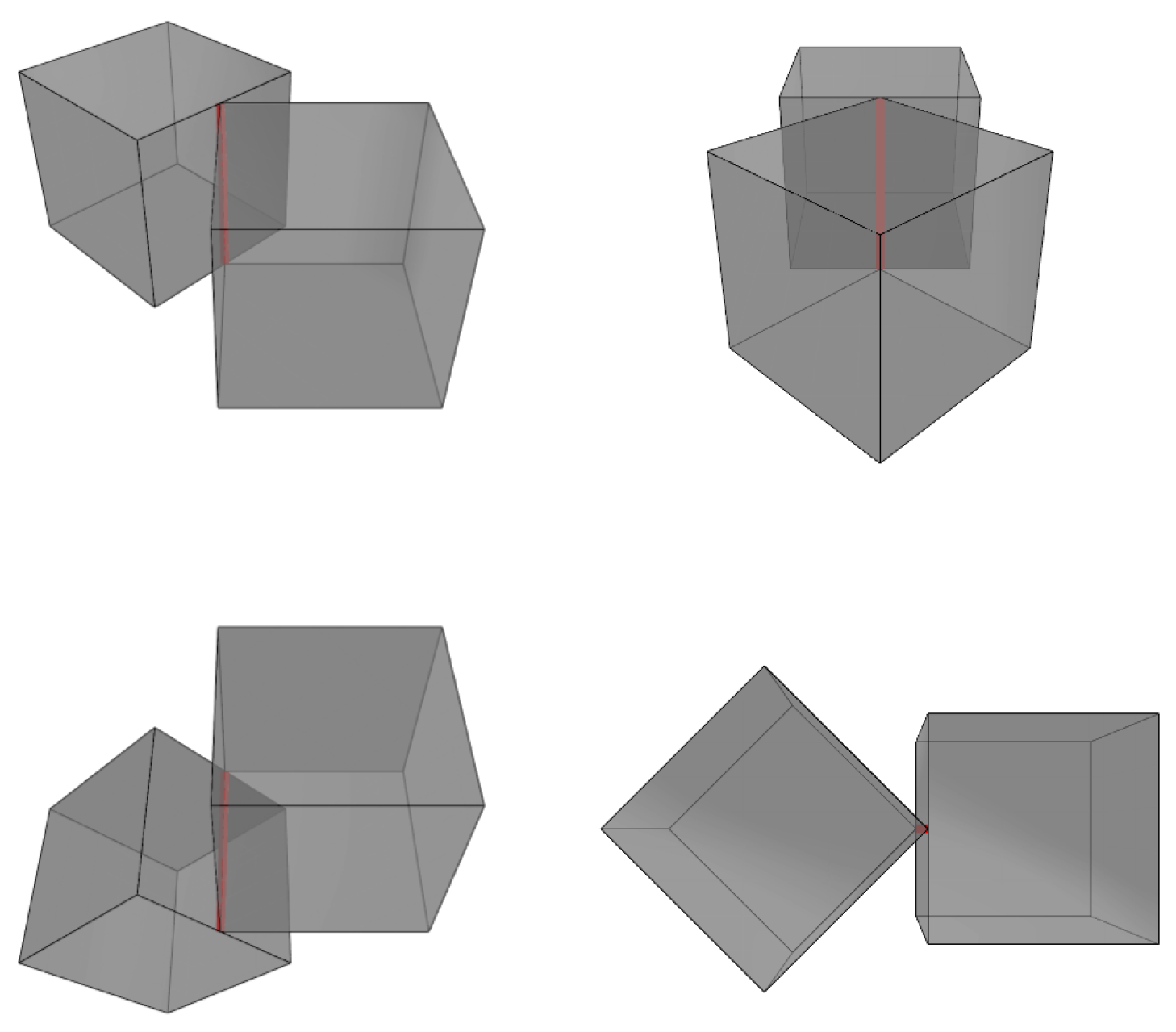
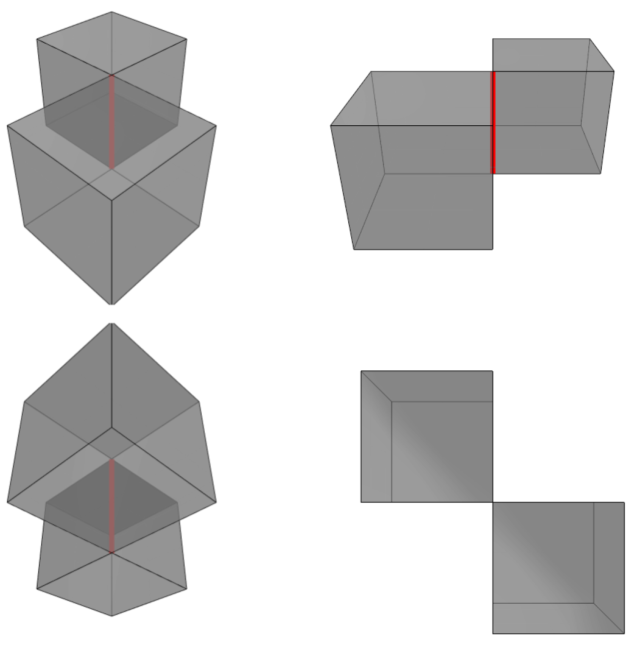
- An edge of block a intersects with a facet of block b. In that case, the point–plane constraints of the plane spanned by that facet for the corner points of the intersecting line segment is added. An example of such a contact is depicted in Figure 20. There, two cubes intersect at an edge of one cube and the interior of a facet of the other.
- A convex edge of block a intersects a convex edge of block b. There are two facets of block a adjacent to the edge of a. In that case, it suffices that one of the two point–plane constraints of the planes spanned by those facets is fulfilled for both corner points of the intersecting line segment. This can be achieved by introducing a binary variable to the linear program that keeps track of which of the two constraints is fulfilled. An example of that contact type is the contact of two cubes along an edge. Figure 21 shows a picture of such a contact.
- A concave edge of block a intersects a convex edge of block b. In that case, the feasible region for the infinitesimal motions of the contact points on b relative to a is convex. This is realized in the linear program by adding the point–plane constraints for both planes spanned by the facets of a adjacent to the concave edge for the corner points of the intersecting line segment. This contact type arises, for example, in the assembly in Application 1 (see Figure 22). Not modelling those contacts in the linear program is the reason why it is not possible to give a certificate of the interlocking property for the assemblies in Section 3.2.1 by applying the method proposed by Wang et al.
4. Conclusions
Author Contributions
Funding
Data Availability Statement
Conflicts of Interest
References
- Beckmann, B.; Bielak, J.; Bosbach, S.; Scheerer, S.; Schmidt, C.; Hegger, J.; Curbach, M. Collaborative research on carbon reinforced concrete structures in the CRC/TRR 280 project. Civ. Eng. Des. 2021, 3, 99–109. [Google Scholar] [CrossRef]
- Spartali, H.; Hegger, J.; Chudoba, R. Phenomenological comparison between the flexural performance of steel- and CFRP-reinforced concrete elements. Eng. Struct. 2023, 294, 116755. [Google Scholar] [CrossRef]
- Preinstorfer, P.; Huber, T.; Reichenbach, S.; Lees, J.M.; Kromoser, B. Parametric Design Studies of Mass-Related Global Warming Potential and Construction Costs of FRP-Reinforced Concrete Infrastructure. Polymers 2022, 14, 2383. [Google Scholar] [CrossRef] [PubMed]
- Beckmann, B.; Adam, V.; Marx, S.; Chudoba, R.; Hegger, J.; Curbach, M. Novel Design Strategies for Material-Minimized Carbon Reinforced Concrete Structures—Overview of the Research in CRC/TRR 280. In Proceedings of the Building for the Future: Durable, Sustainable, Resilient; Ilki, A., Çavunt, D., Çavunt, Y.S., Eds.; Springer: Cham, Switzerland, 2023; pp. 1242–1251. [Google Scholar]
- Hawkins, W.; Orr, J.; Ibell, T.; Shepherd, P. A design methodology to reduce the embodied carbon of concrete buildings using thin-shell floors. Eng. Struct. 2020, 207, 110195. [Google Scholar] [CrossRef]
- Vakaliuk, I.; Goertzen, T.; Scheerer, S.; Niemeyer, A.C.; Curbach, M. Initial Numerical Development of Design Procedures for TRC Bioinspired Shells. In Proceedings of the Innovation, Sustainability and Legacy—Proceedings of IASS/APCS 2022, Beijing, China, 19–22 September 2022; Xue, S.D., Wu, J.Z., Sun, G.J., Eds.; IASS International Association for Shell and Spatial Structures: Madrid, Spain, 2022; pp. 2597–2608. [Google Scholar]
- Vakaliuk, I.; Scheerer, S.; Curbach, M. Initial Laboratory Test of Load-Bearing Shell-Shaped TRC Structures. In Proceedings of the Concrete Innovation for Sustainability—Proceedings for the 6th fib International Congress 2022, Oslo, Norway, 12–16 June 2022; Stokkeland, S., Braarud, H.C., Eds.; fib—International Federation for Structural Concrete: Lausanne, Switzerland, 2022; pp. 675–684. [Google Scholar]
- Chudoba, R.; Brakhage, K. Rigid-Facet Kinematics Coupled with Finite Bending Rotation Along Crease Lines. In Proceedings of the 7th International Meeting on Origami in Science, Mathematics, and Education, Oxford, UK, 5–7 September 2018. [Google Scholar]
- Chudoba, R.; Sharei, E.; Senckpiel, T.; Schladitz, F. Numerical Modeling of Non-Uniformly Reinforced Carbon Concrete Lightweight Ceiling Elements. Appl. Sci. 2019, 9, 2438. [Google Scholar] [CrossRef]
- Chudoba, R.; van der Woerd, J.; Schmerl, M.; Hegger, J. ORICRETE: Modeling support for design and manufacturing of folded concrete structures. Adv. Eng. Softw. 2014, 72, 119–127. [Google Scholar] [CrossRef]
- Bobenko, A.I.; Suris, Y.B. Discrete Differential Geometry: Integrable Structure; American Mathematical Society: Washington, DC, USA, 2008. [Google Scholar]
- Brakhage, K.H.; Niemeyer, A.; Plesken, W.; Strzelczyk, A. Simplicial Surfaces Controlled by One Triangle. J. Geom. Graph. 2017, 21, 141–152. [Google Scholar]
- Brakhage, K.H.; Niemeyer, A.C.; Plesken, W.; Robertz, D.; Strzelczyk, A. The icosahedra of edge length 1. J. Algebra 2020, 545, 4–26. [Google Scholar] [CrossRef]
- Sulanke, T.; Lutz, F.H. Isomorphism-free lexicographic enumeration of triangulated surfaces and 3-manifolds. Eur. J. Comb. 2009, 30, 1965–1979. [Google Scholar] [CrossRef]
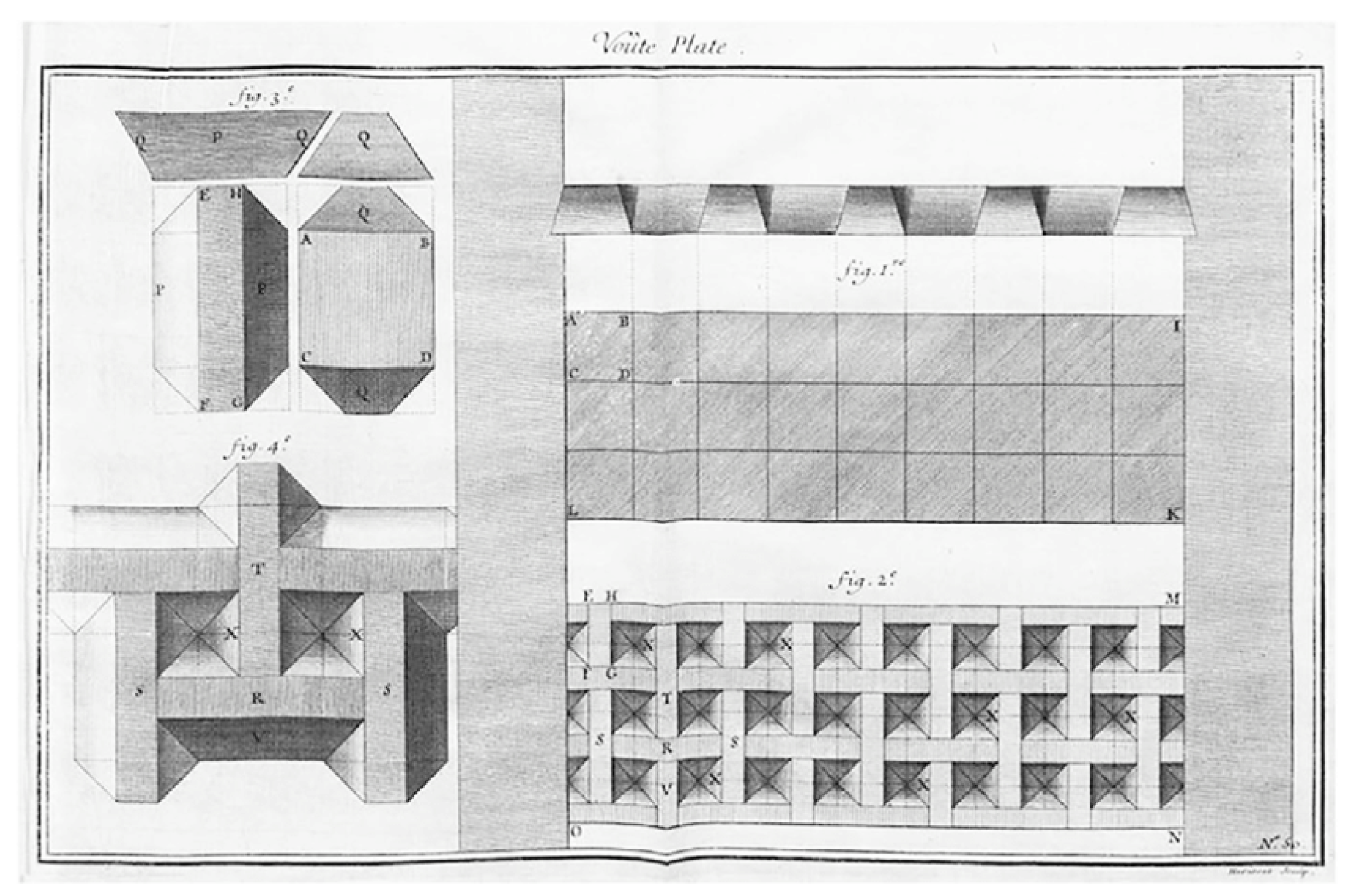
- Moreno Gata, K.; Mueller, C.; Valiente, E. Designing Strategies for Topological Interlocking Assemblies in Architecture. Flat Vaults. In Proceedings of the IASS Annual Symposium 2019, Structural Membranes 2019, Form and Force; IASS International Association for shell and spatial structures: Madrid, Spain, 2019. ISSN 2518-6582. [Google Scholar]
- Abeille, J. Mémoire Concernant la Voûte Plate Inventée par M. Abeille; Académie Royale des Sciences, Machines et Inventions Approuvées par l’Académie Royale des Sciences depuis son Établissement jusqu’à Present; avec Leur Description. Dessinées & Publiées du Consentement de l’Académie; Académie des Sciences: Paris, France, 1735; Volume 1, pp. 159–162. [Google Scholar] [CrossRef]
- Glickmann, M. The G-Block System of Vertically Interlocking Paving. In Proceedings of the Second International Conference on Concrete Block Paving, Delft, The Netherlands, 10–12 April 1984. [Google Scholar]
- Dyskin, A.; Estrin, Y.; Kanel-Belov, A.; Pasternak, E. A new concept in design of materials and structures: Assemblies of interlocked tetrahedron-shaped elements. Scipta Mater. 2001, 44, 2689–2694. [Google Scholar] [CrossRef]
- Estrin, Y.; Krishnamurthy, V.R.; Akleman, E. Design of architectured materials based on topological and geometrical interlocking. J. Mater. Res. Technol. 2021, 15, 1165–1178. [Google Scholar] [CrossRef]
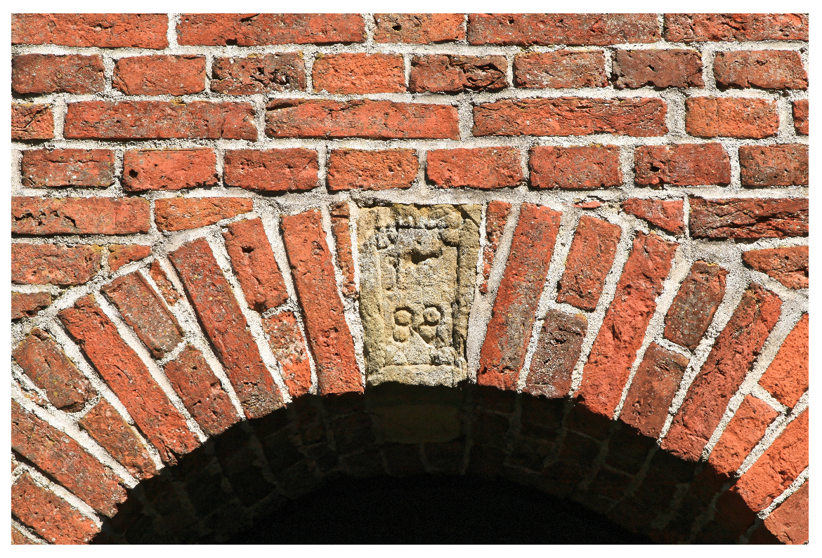
- Vincentz, F. Schlussstein von 1788 in einem Torbogen des Wymeerer Glockenturms. Available online: https://commons.m.wikimedia.org/wiki/File:Bunde_Wymeer_-_Kirchstra%C3%9Fe_-_Glockenturm_07_ies.jpg (accessed on 3 September 2023).
- Wang, Z.; Song, P.; Isvoranu, F.; Pauly, M. Design and Structural Optimization of Topological Interlocking Assemblies. ACM Trans. Graph. 2019, 38, 193. [Google Scholar] [CrossRef]
- Bezanson, J.; Edelman, A.; Karpinski, S.; Shah, V.B. Julia: A fresh approach to numerical computing. SIAM Rev. 2017, 59, 65–98. [Google Scholar] [CrossRef]
- Legat, B. Polyhedral Computation, JuliaCon 2023, Cambridge, MA, USA. 2023. Available online: https://pretalx.com/juliacon2023/talk/JP3SPX/ (accessed on 3 September 2023).
- Lubin, M.; Dowson, O.; Dias Garcia, J.; Huchette, J.; Legat, B.; Vielma, J.P. JuMP 1.0: Recent improvements to a modeling language for mathematical optimization. Math. Program. Comput. 2023. [Google Scholar] [CrossRef]
- Huangfu, Q.; Hall, J.A.J. Parallelizing the dual revised simplex method. Math. Program. Comput. 2018, 10, 119–142. [Google Scholar] [CrossRef]
- Plotly Technologies Inc. Collaborative Data Science; Plotly Technologies Inc.: Montreal, QC, Canada, 2015; Available online: https://plot.ly (accessed on 3 September 2023).
- Akpanya, R.; Stüttgen, S. Non-Convex-Interlocking, Version 0.1; GitHub: San Francisco, CA, USA, 2023. Available online: https://github.com/ReymondAkpanya/Non-convex-Interlocking-(accessed on 3 September 2023).
- Akpanya, R.; Baumeister, M.; Görtzen, T.; Niemeyer, A.; Weiß, M. SimplicicalSurfaces—A GAP Package, Version 0.6. 2023. Available online: https://github.com/gap-packages/SimplicialSurfaces (accessed on 3 September 2023).
- The GAP Group. GAP—Groups, Algorithms & Programming, Version 4.12.2. 2022. Available online: https://www.gap-system.org (accessed on 3 September 2023).
- Neef, T. Schalenstrukturen aus Verriegelungsblöcken. 2023. Available online: https://www.sfbtrr280.de/news/news/detail/schalenstrukturen-aus-verriegelungsbloecken (accessed on 5 October 2023).
- Neef, T.; Dittel, G.; Scheurer, M.; Gries, T.; Mechtcherine, V. Utilizing Textiles as Integrated Formwork for Additive Manufacturing with Concrete. In Proceedings of the Building for the Future: Durable, Sustainable, Resilient; Ilki, A., Çavunt, D., Çavunt, Y.S., Eds.; Springer: Cham, Switzerland, 2023; pp. 1285–1292. [Google Scholar] [CrossRef]
- Neef, T.; Müller, S.; Mechtcherine, V. Integration of Mineral Impregnated Carbon Fibre (MCF) into Fine 3D-Printed Concrete Filaments. In Proceedings of the Third RILEM International Conference on Concrete and Digital Fabrication; Buswell, R., Blanco, A., Cavalaro, S., Kinnell, P., Eds.; Springer: Cham, Switzerland, 2022; pp. 397–403. [Google Scholar] [CrossRef]
- Akpanya, R.; Goertzen, T.; Niemeyer, A. A Group-Theoretic Approach for Constructing Spherical-Interlocking Assemblies. In Proceedings of the Annual Symposium of the International Association for Shell and Spatial Structures (IASS 2023), Melbourne, Australia, 10–14 July 2023. [Google Scholar]
- Goertzen, T.; Niemeyer, A.; Plesken, W. Topological Interlocking via Symmetry. In Proceedings of the 6th FIB International Congress 2022, Oslo, Norway, 12–16 June 2022; Novus Press: Oslo, Norway, 2022. [Google Scholar]


Disclaimer/Publisher’s Note: The statements, opinions and data contained in all publications are solely those of the individual author(s) and contributor(s) and not of MDPI and/or the editor(s). MDPI and/or the editor(s) disclaim responsibility for any injury to people or property resulting from any ideas, methods, instructions or products referred to in the content. |
© 2023 by the authors. Licensee MDPI, Basel, Switzerland. This article is an open access article distributed under the terms and conditions of the Creative Commons Attribution (CC BY) license (https://creativecommons.org/licenses/by/4.0/).
Share and Cite
Stüttgen, S.; Akpanya, R.; Beckmann, B.; Chudoba, R.; Robertz, D.; Niemeyer, A.C. Modular Construction of Topological Interlocking Blocks—An Algebraic Approach for Resource-Efficient Carbon-Reinforced Concrete Structures. Buildings 2023, 13, 2565. https://doi.org/10.3390/buildings13102565
Stüttgen S, Akpanya R, Beckmann B, Chudoba R, Robertz D, Niemeyer AC. Modular Construction of Topological Interlocking Blocks—An Algebraic Approach for Resource-Efficient Carbon-Reinforced Concrete Structures. Buildings. 2023; 13(10):2565. https://doi.org/10.3390/buildings13102565
Chicago/Turabian StyleStüttgen, Sascha, Reymond Akpanya, Birgit Beckmann, Rostislav Chudoba, Daniel Robertz, and Alice C. Niemeyer. 2023. "Modular Construction of Topological Interlocking Blocks—An Algebraic Approach for Resource-Efficient Carbon-Reinforced Concrete Structures" Buildings 13, no. 10: 2565. https://doi.org/10.3390/buildings13102565