Article

Optimized Design of a Tuned Mass Damper Inerter (TMDI) Applied to Circular Section Members of Transmission Towers

1
School of Civil Engineering and Architecture, Chongqing University of Science & Technology, Chongqing 401331, China
2
Chongqing Key Laboratory of Energy Engineering Mechanics & Disaster Prevention and Mitigation, Chongqing 401331, China
*
Author to whom correspondence should be addressed.
Buildings 2022, 12(8), 1154; https://doi.org/10.3390/buildings12081154
Submission received: 5 July 2022 / Revised: 25 July 2022 / Accepted: 29 July 2022 / Published: 2 August 2022

Abstract

:
Wind loads can cause significant vibrations in circular section members, resulting in serious structural hazards. In order to control the vibration of the structure and mitigate the hazards, this study investigates the optimal design and carries out a performance evaluation of a tuned mass damper inerter (TMDI) designed for the vibration control of circular section members in structures. The TMDI system is a novel vibration reduction device that utilizes an inerter based on a tuned mass damper (TMD). The main structure is a simplified Euler beam made up of circular section members, and the mass of the TMDI is coupled to the main structure by a spring and damper, as well as to the ground via an inerter. The optimization objectives are to minimize the displacement variance and maximize the energy dissipation index (EDI), and two different optimization schemes are designed. In addition to the comparative analysis of the results obtained from the different optimization schemes, a sensitivity analysis of the design parameters is also performed, and the results show that TMDI not only effectively reduces the additional mass but also has better vibration control performance and robustness than the TMD.

1. Introduction

Transmission line towers have evolved from timber structures to cement structures to metal structures in tandem with the rapid advancement of world technology and commerce. Metal pylons are now widely employed in a wide range of transmission lines, particularly in high-voltage transmission lines. The safety and stability of energy transmission lines should be given significant attention, because having a stable energy supply is crucial for economic development.
The effect of wind loads on long-span structures is known to be significant. Studies on the full-bridge aeroelastic model have illustrated this phenomenon [1,2], and this research also provides a reference for wind-resistant studies of long-span structures. Ultrahigh-voltage (UHV) transmission towers, as large-span structures, also face wind resistance design problems. The cross-arms of UHV transmission towers are round section rods, and these round tube rods produce more visible vibrations under wind load. This vibration phenomenon is known as aeolian vibration in engineering. When the wind passes through the surface of the circular section member, it generates a vortex that sheds regularly on the top and bottom sides of the back of the circular section member, producing an alternating force that acts on the circular section member, and, when the frequency of this alternating force is close to the member frequency, it causes vortex excitation resonance. The cross-arms of UHV transmission towers are made of circular tube members connected by flange bolts. Repeated vibration of circular section members can produce fatigue damage to the structure, which will result in significant economic loss and put the lives and safety of the surrounding personnel in jeopardy. To avoid this situation, vibration control of circular section cross-arms is required; therefore, an investigation was carried out in this study. Since there are relatively few studies on the vibration control of circular section members of transmission towers, this study first investigated the use of novel tuned mass dampers which, together with isolators [3,4] and energy dissipation bearings [5,6], represent one of the most frequently used types of passive vibration control devices in the field of structural vibration control.
The tuned mass damper (TMD) is well known in the field of vibration control [7,8]. The TMD is a device that connects a secondary mass to the main structure by a spring and damper. It has a wide range of applications in aerospace, civil, and mechanical engineering because of its simple structural design, ease of maintenance, high dependability, and improved vibration control effects. Khodaie [9] conducted a study on super-tall buildings and found that the combination of the tapering method and TMD can effectively control vibration in buildings. Liu [10] optimized the design of the TMD by considering the stroke of the TMD and its vibration control performance and obtained a design method that not only ensures good vibration control performance but also reduces the stroke of the TMD, which improves its reliability in structures. Liu et al. [11] found that a damped TMD can effectively control the displacement response and acceleration response of the structure by conducting full-scale shaking table tests on assembled flexural steel frames and ensuring that the structure remains within the elastic range under designed seismic action. Domizio et al. [12] aimed to control the dynamic response of the structure under seismic excitation by optimizing different configurations of the TMD and found that the double-TMD structure has the highest effectiveness, whereas the single-TMD structure has the best robustness. Hosseini Lavassani et al. [13] found that the combination of magnetorheological dampers (MRs) and the TMD is most effective for reducing the displacement of buildings under seismic excitation. Li et al. [14] proposed a shim TMD and proved through a study that the shim TMD can effectively suppress multimodal vibration. They applied shim TMD to control the vibration of the suspension. Li et al. [15] established a dynamic model based on the theory of dynamic action of train track bridges and the TMD design method, and they found that the installation of a TMD on a bridge can effectively improve the train operation stability and ensure the safety of trains. Fang et al. [16] investigated a double-beam system model with the TMD theory, considering the main beam as the primary structure and the secondary beam as the TMD, and they found that both the primary and secondary beams can achieve the minimum displacement value when the system is optimally adjusted. Zhang and Xu considered nonlinear factors and set nonlinear control objectives when applying the TMD [17]. The study found that more economical control parameters can be obtained by considering nonlinear factors. At the same time, the optimization objective and optimization method considering nonlinearities have stronger reliability and superiority. This finding has very important implications for our future research work. Nevertheless, there are still some drawbacks of the TMD [18]. The TMD is obviously affected by the nonlinear behavior of structures, typically has a hysteretic nature [19,20], and is prone to detuning, which affects its vibration suppression performance. The vibration suppression performance of the TMD is largely determined by the size of the additional mass, where a larger additional mass results in a better vibration suppression performance of the TMD; however, but the size of the additional mass is constrained by the structural space and the manufacturing price.
Therefore, Smith [21] proposed the application of inertial machines. An ideal inerter is a mechanical element with two free terminals capable of generating a drag force that is internally proportional to the magnitude of the acceleration to balance the loading of forces on the free terminals. On the basis of this definition, we can obtain the following relation:
F = b ( u ¨ 2 u ¨ 1 ) ,
where b represents the inertia value, u ¨ 1 is the acceleration of the main structure, and u ¨ 2 denotes the acceleration of the accessory structure.
Due to the mass amplification effect and negative stiffness effect of the inerter [22], it can significantly improve the performance of the energy dissipator and effectively control the vibration of the structure. The inerter has been widely used in the field of structural vibration control. In a study about tuned inerter dampers (TIDs) and the control of the response of adjacent structures in seismic excitation, Djerouni et al. [23] found that the original configuration is better for controlling the displacement response of its own structure and lacks better control for the displacement responses of adjacent structures. Thus, a new configuration was proposed on the basis of the original configuration, and, through an evaluation, it was found that the new configuration could effectively control the displacement response of the adjacent structure. Shi et al. [24] demonstrated the effectiveness of inertial devices in vibration control systems by applying TIDs in linear and nonlinear systems. Wen et al. [25] constructed a generalized optimal TID design to investigate the case of a multiple-degree-of-freedom structure subjected to random excitation, and the results showed that the optimized results effectively improved the vibration control capability of the device. Xu et al. [26] also proposed an analytical method for the optimal design of TIDs in multiple-degree-of-freedom structures based on equivalent transformation. Su et al. [27] investigated the vibration control performance of the TMDI using the filtering method and found that the TMDI has a significant controlling effect on the wind vibration response of high-rise buildings. Zhang and Fitzgerald installed the TMDI at the edge of the wind turbine blade and found through a numerical simulation that the TMDI has a better controlling effect on vibration than the TMD. Meanwhile, inertia has a significant controlling effect on the travel of damping [28]. De Angelis et al. [29] conducted a study on the application of the TMDI to pedestrian bridges and obtained the two best topology configurations. Kaveh et al. [30] used the TMDI on a 10-story shear building to demonstrate the robustness of the TMDI system. Wang [31] proposed the use of top-level softening based on structural dynamics, which significantly reduces the sensitivity of the TMDI to the optimal parameters and enhances its robustness and stability. Djerouni et al. [32] used the genetic algorithm to optimize the design of the backward-shared tuned mass damper inerter (BSTMDI) to minimize story drift. The robustness of BSTMDI was verified using a large number of real earthquake records. Pietrosanti [33] considered the nonlinearity of the structure under seismic excitation and found that the nonlinearity of the structure does not have a significant effect on the TMDI. Kakou and Barry proposed the electromagnetic resonant shunt tuned mass damper inerter (ERS-TMDI) and applied it to nonlinear structures. It was able to carry out energy harvesting along with the vibration control function [34]. In view of the multiple advantages of the TMD and inerter combined in a TMDI device, we now consider the application of the TMDI to circular section members in buildings to achieve the purpose of controlling the vortex-induced vibration (VIV).
There are two main novel aspects in this study. First, most of the previous TMDIs have been applied to the study of the vibration control of transmission conductors and wind turbine blades. At present, little research has been conducted on the vibration control of circular section members of transmission towers. Studies are urgently needed to enrich the research area. In this study, we expand the circular section cross-arms of transmission towers to circular section members in structures, optimize the design, and evaluate the performance of the TMDI devices. The application of the TMDI to the vibration control study of crossbars of round tube steel transmission towers is novel. This research fully considers the characteristics of high-rise structures and large-span structures that are significantly affected by wind load effects and conducts a vibration control study on circular section members in structures. Secondly, in this study, the infinite degrees of freedom of the structure are taken into account in the model design. When building the theoretical model, we consider the model with infinite degrees of freedom instead of the single-degree-of-freedom model, which makes the theoretical model more reasonable and the results obtained from the analysis more accurate. This investigation can effectively guarantee the safe operation of the structure during its life cycle. This study combines a generic model with an optimal design approach to improve this aspect of vibration control research. First, the circular section member in structures is simplified to a Eulerian beam model with a linear stiffness and mass distribution, and a traditional TMD is added to the beam. The additional mass is coupled to the beam by a spring and damper, and the additional mass is grounded by an inerter. Then, a zero-mean white noise random process is assumed as the input load. The structural displacement variance and energy dissipation index (EDI) are introduced to analyze the effectiveness of the TMDI device for structural vibration control by investigating the displacement response and energy dissipation of the combined system under the action of random loads. The robustness of the TMDI device is analyzed by performing a sensitivity assessment on the performance of the combined system.
The remainder of the article is organized as follows: Section 2 discusses the theoretical model of the TMDI, the governing equations of motion of the combined system, and the excitation. Section 3 describes the optimal design of the TMDI with two proposed objective functions (Ofs), including an energy-based criterion. Section 4 reports the results of the optimal design, the performance, and the comparisons of different parameter groups of the TMDI system. The robustness of the TMDI system is then evaluated via a sensitivity analysis. Lastly, Section 5 synthesizes the main findings of the work.

2. Design Methodology of TMDI System

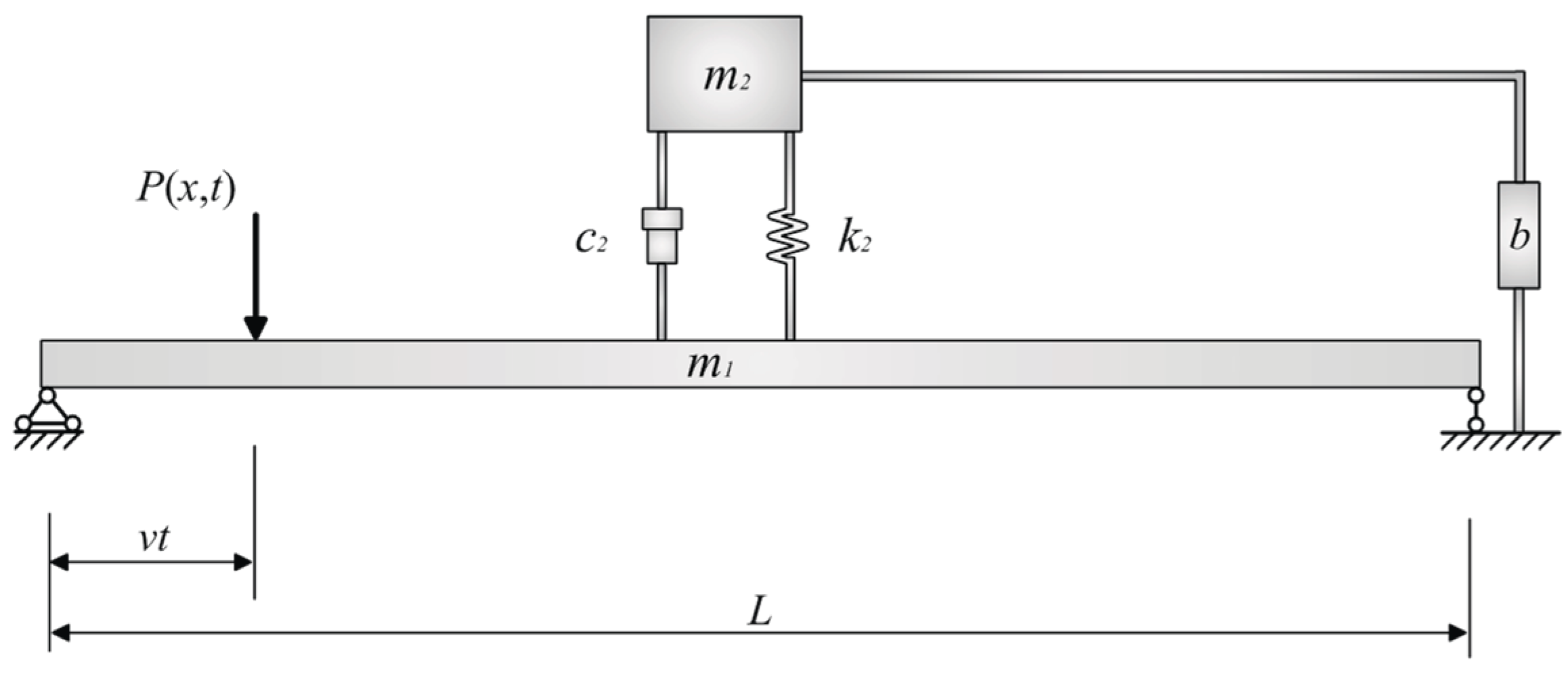
2.1. Theoretical Model

Figure 1 shows part of the structure of the transmission tower. In this part of the structure, midpoint 1 of the crossbar is connected to intersection 2 of the two diagonal bars through the TMDI. By observing the actual vibration of the structure, we know that vibration mainly occurs on the crossbar. Therefore, we used the vibration of the crossbar as the control target. Since it is difficult to deform the ends of the crossbar fixed to the main material, and because the deformation mainly occurs in the middle of the crossbar, the crossbar of the transmission tower can be simplified as a Euler beam model. Compared with the crossbar, the vibration of the diagonal bar due to the load is negligible. Therefore, we treated the diagonal bar as a fixed and constant part. We approximated that the grounding of the TMDI was achieved by connecting midpoint 1 to intersection 2.
The structural configuration of the system is shown in Figure 2.
In Figure 2, the primary structure is a Euler beam with a perfectly uniform linear distribution of mass and stiffness, with mass m 1 , stiffness k 1 , and viscous damping c 1 . The accessory structure is connected to the mass m 1 of the primary structure through a linear elastic spring with stiffness k 2 and a linear dashpot with the viscous damping coefficient c 2 . The mass m 2 of the accessory structure is connected to the nondisplaced part through an inerter with inertance b.

2.2. Governing Equations

The equations of motion for the system shown in Figure 2 under load excitation are given below [35].
m 1 2 x 1 ( x , t ) t 2 + c 1 x 1 ( x , t ) t + E I ( x ) 4 x 1 ( x , t ) x 4 + k 1 x 1 ( x , t ) = P ( x , t ) + c 2 [ x 2 ( x , t ) t x 1 ( x , t ) t ] + k 2 [ x 2 ( x , t ) x 1 ( x , t ) ] ,
m 2 2 x 2 ( x , t ) t 2 + c 2 [ x 2 ( x , t ) t x 1 ( x , t ) t ] + k 2 [ x 2 ( x , t ) x 1 ( x , t ) ] + b 2 x 2 ( x , t ) t 2 = 0 ,
where the wind load P ( x , t ) along the length of the beam, the flexural stiffness E I ( x ) , the displacement x 1 ( x , t ) occurring in the beam, and the displacement x 2 ( x , t ) occurring in the TMDI are all functions that vary continuously with time t and between coordinates x.
According to the theory of the modal analysis method [36],
x 1 ( x , t ) = m = 1 ϕ m ( x ) q m ( t ) ,
where ϕ m denotes the shape of the vibration and does not change with time, and q m denotes the amplitude, which varies with time.
By substituting Equation (4) into Equation (3), the load part of the beam can be written as
P n ( x , t ) = 0 L δ ( x v t ) { k 2 x 2 ( x , t ) + c 2 x ˙ 2 ( x , t ) m = 1 [ k 2 ϕ m ( x ) q m ( t ) + c 2 ϕ m ( x ) q ˙ m ( t ) ] + P ( x , t ) } ϕ n ( x ) d x ,
where vt represents the position of the load acting on the beam. A dot above the variable indicates the derivative of time t.
In Equation (5), δ is the Dirac function [36], which is very useful and has the following two properties, where d is a parameter:
δ ( x d ) = { 1 , 0 ,   x = d x d ,
a b δ ( x d ) f ( x ) d x = f ( x ) ( a < d < b ) .
The normalized mode function of the simply supported beam model is shown below [36].
ϕ ( x ) = sin n π x L ,
where L is the length of the beam.
Therefore, the oscillating mass of the simply supported beam is expressed as follows [36]:
M n = 0 L m ¯ sin 2 n π x L d x = m ¯ L 2   ( n = 1 , 2 , · · · , ) ,
where m ¯ is the mass per unit length of the beam.
According to the two properties of the Dirac function and Equations (5) and (8), the beam load part can be written as
P n ( x , t ) = P ( x , t ) sin n π x L + [ k 2 x 2 ( x , t ) + c 2 x ˙ 2 ( x , t ) ] sin n π x L m = 1 [ k 2 q m ( t ) + c 2 q ˙ m ( t ) ] sin m π x L sin n π x L .
According to the basic knowledge of structural dynamics [37],
c = 2 m ξ ω ,   k = m ω 2 ,
where c is the damping coefficient, m is the mass, ξ is the damping ratio, ω is the natural frequency, and k is the stiffness.
By substituting Equations (9) and (10), Equation (2) can be written in the following form:
q ¨ m ( t ) + 2 ξ 1 ω 1 q ˙ m ( t ) + ω 1 2 q m ( t ) = 2 m ¯ L { P ( x , t ) sin n π x L + [ k 2 x 2 ( x , t ) + c 2 x ˙ 2 ( x , t ) ] sin n π x L m = 1 [ k 2 q m ( t ) + c 2 q ˙ m ( t ) ] sin m π x L sin n π x L } ,
where ξ 1 is the damping ratio of the beam, and ω 1 is the inherent frequency of the beam.
Similarly, by expressing the equations of motion of the TMDI structure in terms of the principle of superposition of vibrations, Equation (3) can be written in the following form:
m 2 x ¨ 2 ( x , t ) + c 2 x ˙ 2 ( x , t ) + k 2 x 2 ( x , t ) c 2 ϕ m ( x ) q ˙ m ( t ) k 2 ϕ m ( x ) q m ( t ) + b x ¨ 2 ( x , t ) = 0 .
By simplifying Equation (13), the following form can be obtained:
x ¨ 2 ( x , t ) + 2 ξ 2 ω 2 x ˙ 2 ( x , t ) + ω 2 2 x 2 ( x , t ) [ 2 ξ 2 ω 2 q ˙ m ( t ) + ω 2 2 q m ( t ) ] sin m π x L + b m 2 x ¨ 2 ( x , t ) = 0 ,
where ξ 2 is the damping ratio of the TMDI, and ω 2 is the intrinsic frequency of the TMDI.
To facilitate the calculation, we present the following definitions: m 2 m 1 = μ is the mass ratio, ω 2 ω 1 = ν is the frequency ratio, and b m 1 = β is the equivalent mass ratio.
On the basis of the above definition, Equation (12) can be written in the following form:
q ¨ m ( t ) + 2 ξ 1 ω 1 q ˙ m ( t ) + ω 1 2 q m ( t ) = 2 { P ( x , t ) m 1 sin n π x L + μ v 2 ω 1 2 x 2 ( x , t ) + 2 μ ν ξ 2 ω 1 x ˙ 2 ( x , t ) sin n π x L m = 1 μ v 2 ω 1 2 q m ( t ) + 2 μ ν ξ 2 ω 1 q ˙ m ( t ) sin m π x L sin n π x L } .
We can express Equation (14) in the following form:
x ¨ 2 ( x , t ) + 2 ν ξ 2 ω 1 x ˙ 2 ( x , t ) + ν 2 ω 1 2 x 2 ( x , t ) [ 2 ν ξ 2 ω 1 q ˙ m ( t ) + ν 2 ω 1 2 q m ( t ) ] sin m π x L + β μ x ¨ 2 ( x , t ) = 0 .
For the sake of observations, q m and x 2 are unified as u 1 and u 2 ; hence, Equations (15) and (16) can be written in the following form:
u ¨ 1 ( t ) + 2 ξ 1 ω 1 u ˙ 1 ( t ) + ω 1 2 u 1 ( t ) = 2 { P ( x , t ) m 1 sin n π x L + [ μ ν 2 ω 1 2 u 2 ( x , t ) + 2 μ ν ξ 2 ω 1 u ˙ 2 ( x , t ) ] sin n π x L m = 1 [ μ ν 2 ω 1 2 u 1 ( t ) + 2 μ ν ξ 2 ω 1 u ˙ 1 ( t ) ] sin m π x L sin n π x L } ,
u ¨ 2 ( x , t ) + 2 ν ξ 2 ω 1 u ¨ 2 ( x , t ) + ν 2 ω 1 2 u 2 ( x , t ) [ 2 ν ξ 2 ω 1 u ˙ 1 ( t ) + ν 2 ω 1 2 u 1 ( t ) ] sin m π x L + β μ u ¨ 2 ( x , t ) = 0 .

2.3. External Excitation and Structural Response

Equations (17) and (18) are expressed in the first-order state space form, as follows [36,38]:
x ˙ ( t ) = A x ( t ) + B u ( t ) ,
where x ˙ ( t ) = ( u 1 ( t ) u 2 ( t ) u ˙ 1 ( t ) u ¨ 2 ( t ) ) T is the state vector.
A = ( 0 0 0 0 0 0 0 0 ( 2 L μ ν 2 + 1 ) ω 1 2 2 L μ ν 2 ω 1 2 2 ( 2 L μ ν ξ 2 + ξ 1 ) 4 L μ ν ξ 2 ω 1 ν 2 ω 1 2 1 + β μ ν 2 ω 1 2 1 + β μ 2 ν ξ 2 ω 1 1 + β μ 2 ν ξ 2 ω 1 1 + β μ ) ,
where A is the state matrix, B = ( 0   0   1   0 ) T is the output vector, and u ( t ) is the applied input process.
The external excitation is assumed to be a Gaussian zero-mean white noise stochastic process with a power spectral density of S 0 . With zero initial conditions, the mean value of the smooth input process is also zero; hence, the response x ( t ) can be expressed by the covariance matrix G x x , where G x x = E [ x x T ] , the main diagonal elements of G x x are the displacement covariance and velocity covariance, and the nondominant diagonal elements are the displacement covariance and velocity covariance. G x x can be obtained by solving the following Lyapunov equation [39]:
A G x x + G x x A T + 2 π S 0 B B T = 0 .
By solving Equation (21), the matrix G x x can be obtained; therefore, the following required response quantities can be obtained: displacement variance σ u 1 2 , displacement covariance σ u 21 2 , velocity variance σ u ˙ 1 2 and σ u ˙ 2 2 , and velocity covariance σ u ˙ 21 2 .

3. Optimal Design of TMDI
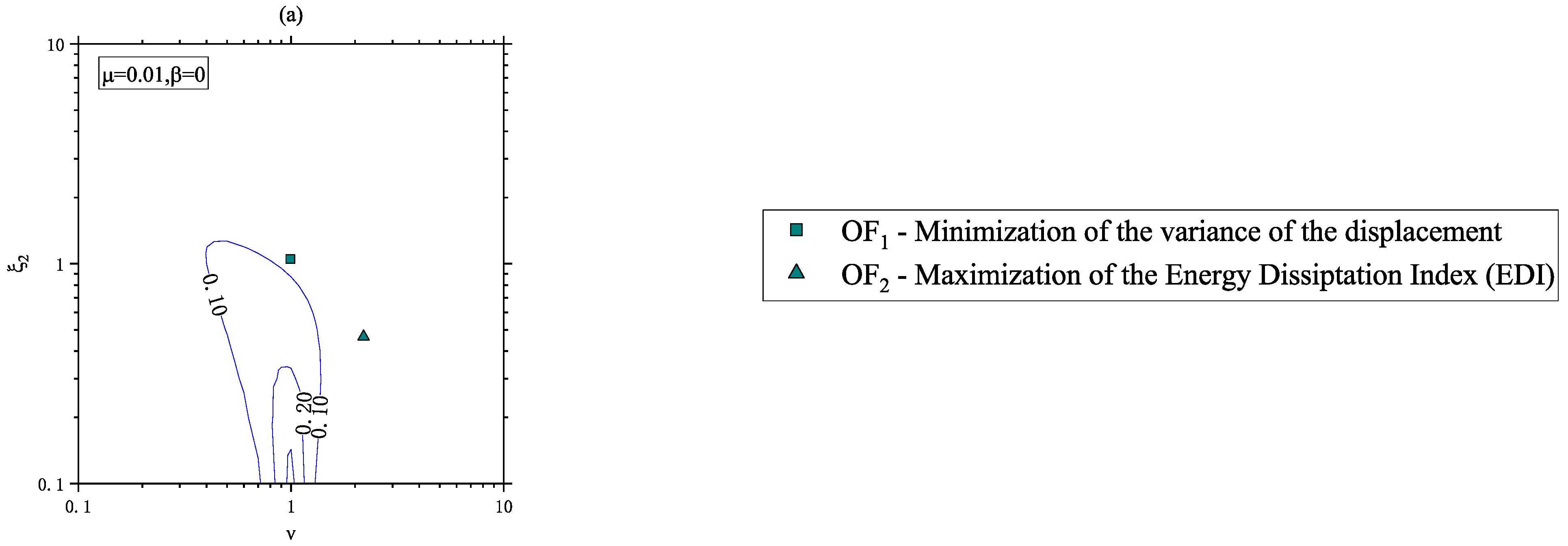
This section discusses the optimal design of a TMDI device applied to the vibration control of circular section members of structures. During the design process, some parameters are assumed to be known, while others are assumed to be mean values and are considered design variables. In this study, μ , β , ν , and ξ 2 were considered design variables, while the remaining parameters were considered to be known quantities. Among them, the mass ratio μ ranges from 0.001 to 1, and the equivalent mass ratio β ranges from 0 to 1 (the TMDI can be considered a classical TMD when β = 0 ). The frequency ratio ν and the damping ratio ξ 2 both take values in the range of 0.01–25.0 and are searched and solved in steps of 10 4 .
In this study, the optimization design was implemented using MATLAB through a numerical search algorithm in a given interval range.
The optimal design can be divided into two steps: the first step is to select a suitable mass ratio μ and equivalent mass ratio β combination; the second step is to perform a search for the optimal frequency ratio ν and damping ratio ξ 2 in each of the combinations selected in the first step. The goal of the optimal design is to obtain the maximum and minimum values of the objective function (OF) in the interval.
According to the objective of this study, two optimization objectives were set with the aim of investigating the performance variation of the TMDI.
(a)
O F 1 : Displacement variance of the beam structure.
The first optimization objective was to minimize the displacement variance of the beam. It is obvious that the internal forces of the structure can be effectively reduced by minimizing the displacement variance of the structure. Therefore,
O F 1 = m i n [ σ u 1 2 ] .
(b)
O F 2 : Energy dissipation index (EDI)
The second optimization objective was proposed on the basis of energy [40,41,42,43,44,45,46,47]. Energy is a reflection of the global situation. According to the theory of relative energy balance, the energy input from wind excitation is dissipated by the TMDI, and if the energy dissipated by the TMDI reaches the maximum value, then the effect of energy input from external wind can be minimized, and the performance of TMDI system can be optimized. Therefore, maximizing the EDI index was taken as the second optimization objective.
O F 2 = m a x [ E D I ] ,
E D I = E [ Δ E d 2 ] E [ Δ E i 1 ] + E [ Δ E i 2 ] ,
where E [ Δ E d 2 ] denotes the expected value of the incremental energy dissipated by the TMDI damping element, and E [ Δ E i 1 ] and E [ Δ E i 2 ] denote the expected values of the incremental energy inputs to the beam and TMDI systems, respectively. The expressions of these increments are as follows:
E [ Δ E d 2 ] = 2 μ ν ξ 2 ω 1 E [ ( u ˙ 2 u ˙ 1 ) 2 ] Δ t ,
E [ Δ E i 1 ] + E [ Δ E i 2 ] = 2 ξ 1 ω 1 E [ u ˙ 1 2 ] Δ t + 2 μ ν ξ 2 ω 1 E [ ( u ˙ 2 u ˙ 1 ) 2 ] Δ t ,
where E [ u ˙ 1 2 ] denotes the velocity variance σ u ˙ 1 2 , and E [ ( u ˙ 2 u ˙ 1 ) 2 ] denotes the velocity covariance σ u ˙ 21 2 . These variances were derived from the covariance matrix derived from Equation (20). Thus, Equations (24) and (25) can be written in the following forms:
E [ Δ E d 2 ] = 2 μ ν ξ 2 ω 1 ( σ u ˙ 2 2 + σ u ˙ 1 2 2 σ u ˙ 21 ) Δ t ,
E [ Δ E i 1 ] + E [ Δ E i 2 ] = 2 ξ 1 ω 1 σ u ˙ 1 2 Δ t + 2 μ ν ξ 2 ω 1 ( σ u ˙ 2 2 + σ u ˙ 1 2 2 σ u ˙ 21 ) Δ t .
Substituting Equations (26) and (27) into Equation (23) yields
E D I = E [ Δ E d 2 ] E [ Δ E i 1 ] + E [ Δ E i 2 ] = 2 μ ν ξ 2 ω 1 ( σ u ˙ 2 2 + σ u ˙ 1 2 2 σ u ˙ 21 ) 2 ξ 1 ω 1 σ u ˙ 1 2 + 2 μ ν ξ 2 ω 1 ( σ u ˙ 2 2 + σ u ˙ 1 2 2 σ u ˙ 21 ) .
From the definition of EDI, it is clear that the value of EDI can vary between zero and one. When the external energy is completely input to the structure and not dissipated by the TMDI, the value of EDI is zero; when all the external energy input is dissipated by the TMDI, the value of EDI is one.
The results of the above two optimization methods are discussed in detail in the next section. All optimization parameters were obtained on the basis of the following parameters: ξ 1 = 0.02, mass ratio μ = 0.001–1, and equivalent mass ratio β = 0–1.

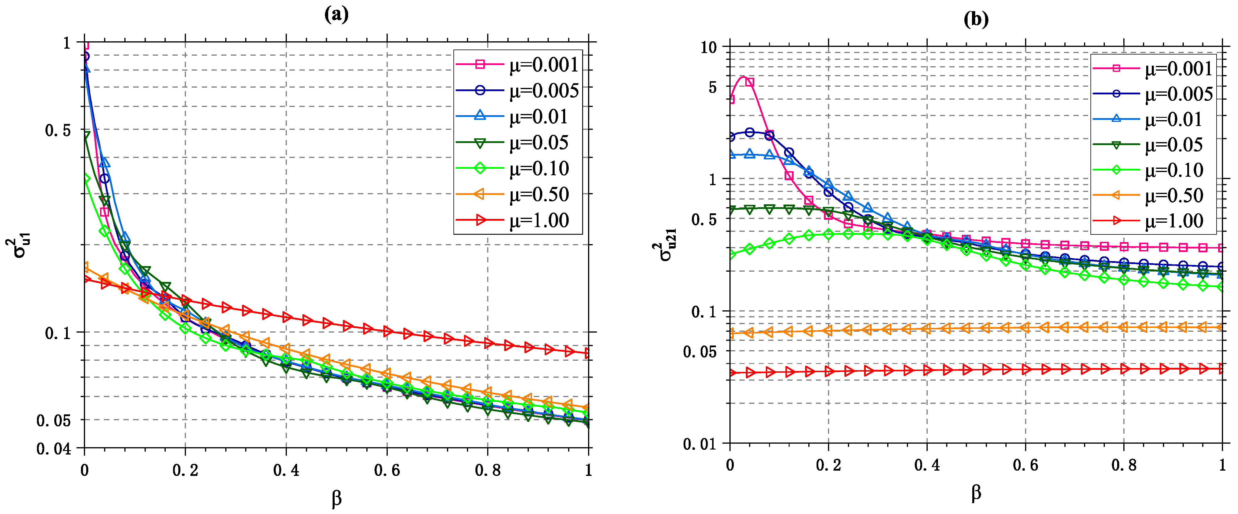
3.1. Minimization of the Displacement Variance of the Beam

Figure 3 shows images with the equivalent mass ratio β as the horizontal coordinate and the mass ratio μ , the optimal damping ratio ξ 2   o p t , and the optimal frequency ratio ν o p t as the vertical coordinates. Each curve represents a different mass ratio μ . For convenience, seven representative values are shown. Figure 3a reflects the change in O F 1 as the equivalent mass ratio β varies from 0 to 1 for several assumed mass ratios μ . In Figure 3a, O F 1 is the ratio of the displacement of the beam equipped with the TMDI system to the displacement of the beam in the free state, which is a normalized quantity; hence, it always varies between 0 and 1. From this setting, it can be concluded that, when the value in Figure 3a is less than 1, the TMDI system can always control the beam vibration effectively. Figure 3b,c reflect the optimal damping ratio ξ 2   o p t , and the optimal frequency ratio ν o p t corresponding to O F 1 for each set of mass ratio μ and equivalent mass ratio β combinations.
The way to use Figure 3a–c is described below. First, the vibration control performance of the TMDI system in Figure 3a is observed, and a desired vibration control performance level is selected. At the desired performance level, the desired mass ratio μ is selected. On the basis of the selected mass ratio μ and its corresponding equivalent mass ratio β , the optimal damping ratio ξ 2   o p t and the optimal frequency ratio ν o p t corresponding to this performance level can be obtained from Figure 3b,c.
We can see from Figure 3 that the value of O F 1 is always smaller than the unit value, which indicates that the TMDI always plays a role in controlling the displacement in the system. Before β = 0.16 , it is observed that the vibration control performance increases with the growth of the mass ratio μ value, which indicates that, when the inertance is small, increasing the additional mass can obtain a better vibration control effect. When β > 0.2 , a small mass ratio is instead able to obtain better vibration control. In addition, we observed that the low-inertance TMDI with β = 0.2 could reduce the vibration of the structure by 88% with a mass ratio of μ = 0.001 , but the large mass TMD with a mass ratio of μ = 0.5 could not reduce the displacement of the structure by more than 84%. Furthermore, for the same mass ratio system, it was observed that the O F 1 value is significantly lower as β increases, which indicates that the vibration control performance of the TMDI is significantly better than that of the TMD. Therefore, the use of TMDI, which can reduce the additional mass and significantly improve the vibration control performance by using only the appropriate inertance, is more effective than the use of the TMD for vibration control.
By observing Figure 3b,c, it can be seen that both the optimal damping ratio ξ 2   o p t and the optimal frequency ratio ν o p t increase as β increases and decrease as the mass ratio μ increases. When the mass ratio is μ = 0.001 , the optimal damping ratio ξ 2   o p t and the optimal frequency ratio ν o p t are significantly greater than the values in other cases; when the mass ratio is μ > 0.5 , the optimal damping ratio ξ 2   o p t and the optimal frequency ratio ν o p t are almost independent of β and do not change as it changes.

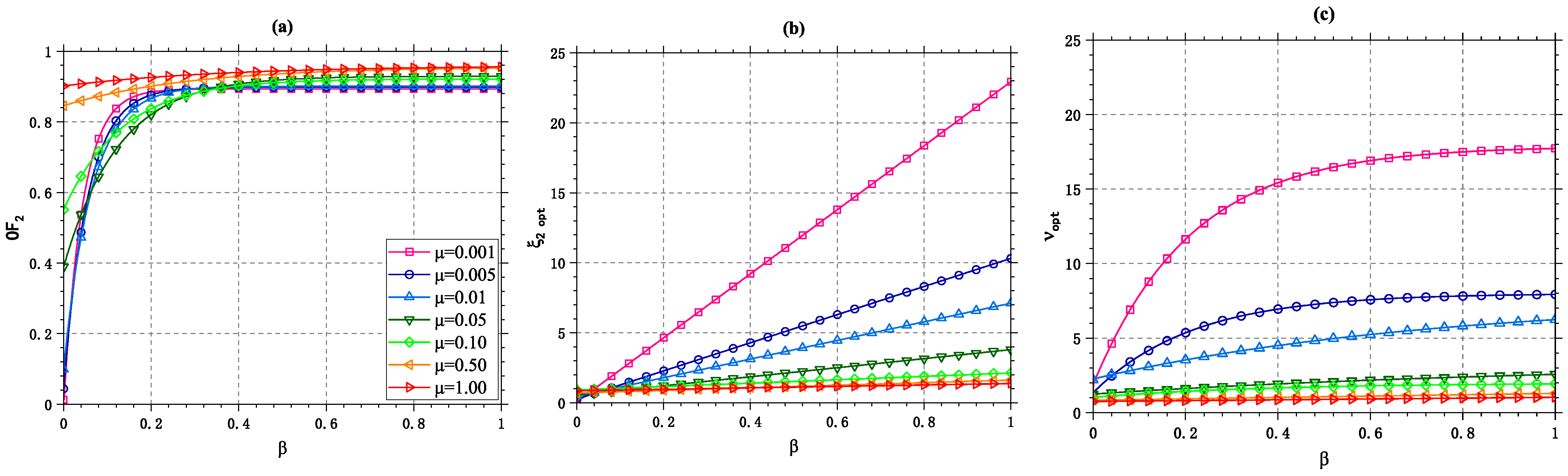
3.2. Maximization of the Energy Dissipation Index (EDI)

O F 2 is a value that varies between 0 and 1, which reflects the strength of the energy dissipation performance. When the input energy is completely dissipated by the TMDI, its value is 1; when the input energy is not dissipated, its value is 0. Figure 4a reflects the variation of O F 2 with β at representative mass ratios. Figure 4b,c reflect the optimal damping ratio ξ 2   o p t and optimal frequency ratio ν o p t corresponding to O F 2 .
By observing Figure 4a, we can see that the value of O F 2 is always greater than 0, which indicates that the TMDI system always carries out energy dissipation effectively. When β = 0 , increasing the mass ratio alone can have the effect of improving the dissipation performance. However, after the introduction of the inerter, with a gradual increase in the mass ratio, the increase rate of O F 2 decreases gradually; when the mass ratio increases to a certain degree, the effect of the inerter is almost negligible, and O F 2 tends toward the limit value of 1. This suggests that, for systems with smaller mass ratios, increasing the inerter can more effectively improve the vibration control performance of the TMDI.
Meanwhile, we observed that the low-inertance TMDI with β = 0.2 can improve the EDI of the structure to 89% with a mass ratio of μ = 0.001, but the large-mass TMD with a mass ratio of μ = 0.5 is unable to improve the energy dissipation index of the structure to more than 85%. Furthermore, for the same mass ratio system, it was observed that the O F 2 value tends to increase with an increase in β. Therefore, it is more economical and efficient to adopt the TMDI, which can reduce the additional mass and significantly improve the energy dissipation performance by using only the appropriate inertance, than to adopt the TMD.
It can be found from Figure 4b,c that the optimal damping ratio ξ 2   o p t and the optimal frequency ratio ν o p t show linear and nonlinear increasing trends, respectively, with an increase in β, whereas they decrease with an increase of the mass ratio μ . When the mass ratio is μ = 0.001 , the optimal damping ratio ξ 2   o p t and the optimal frequency ratio ν o p t are significantly greater than the values in other cases; when the mass ratio is μ > 0.5 , the optimal damping ratio ξ 2   o p t and the optimal frequency ratio ν o p t are almost independent of β and do not change as it changes, which is consistent with Figure 3b,c.

4. Discussion of the Optimization Design Results

In this section, the results of the two design approaches are discussed and compared, focusing on the response of not only the beam but also the response of the accessory structures.

4.1. Comparison of Different Design Methods

From Figure 3b,c and Figure 4b,c, it can be seen that the curves of the optimal damping ratio ξ 2   o p t and the optimal frequency ratio ν o p t obtained by the two design methods are very similar, where the main difference lies in the choices of μ and β . From Figure 3a and Figure 4a, it can be seen that, for systems with small mass ratios ( 0.001 < μ < 0.01 ), the use of the inerter appears to be more effective in the range of β < 0.4 . Using inertial systems for control not only reduces the mass of the system but also significantly improves the control performance of the system. Regardless of the design method, the TMDI is more effective than the TMD for the same mass ratio μ .
Table 1 reflects the variation in the optimal damping ratio ξ 2   o p t and the optimal frequency ratio ν o p t with the variation of β under the same mass ratio μ and according to different design criteria. Since O F 2 is an energy-based design criterion, which can better reflect the global variation, the design methods used in this study are based on O F 2 . It can be observed that, with an increase in μ e , the optimal damping ratio ξ 2   o p t and the optimal frequency ratio ν o p t of different design criteria both show increasing trends. Under the O F 1 criterion, the growth of the optimal damping ratio ξ 2   o p t decreases from 122% to 37% and then to 46%, and the growth of the optimal frequency ratio ν o p t decreases from 57% to 31% and then to 44%. Under the O F 1 criterion, the growth rate of the optimal damping ratio ξ 2   o p t decreases from 122% to 37% and then to 46%, and the growth rate of the optimal frequency ratio ν o p t decreases from 57% to 31% and then to 44%. Under the O F 2 criterion, the growth of the optimal damping ratio ξ 2   o p t decreases from 31% to 21% and then increases to 40%; the growth of the optimal frequency ratio ν o p t decreases from 128% to 62% and then increases to 115%. The changes in the optimal damping ratio ξ 2   o p t and the growth of the optimal frequency ratio ν o p t show the same trend for both design criteria. Additionally, the optimized parameters obtained by the TMDI have higher values compared with those obtained by the TMD.

4.2. Performance Evaluation of the TMDI

Figure 5a is the variance of the displacement of the main structure due to the variation in parameter β for different values of μ . Figure 5b is the variance of the relative displacement due to the variation of parameter β for different mass ratios μ . Figure 5a,b are normalized by the response of the structure in the free uncontrolled state, such that, as long as the values of σ u 1 2 and σ u 21 2 are below the unit value, the control performance of the system is effective.
It is obvious from Figure 5a that the displacement variance σ u 1 2 of the TMDI with inertia participation is always less than 1 and always less than the value of β = 0 . This indicates that the vibration control performance of the TMDI is always effective and always better than the vibration control performance of the TMD. For example, at μ = 0.05 , the TMD reduces the displacement variance of the system by 52%, while, at the same mass ratio, the TMDI with β = 0.2 reduces the displacement variance of the system by 86%, which proves that the advantage of the TMDI over the TMD always exists. Meanwhile, it can be observed in Figure 5a that the improvement of vibration control performance is always accompanied by an increase in the mass ratio μ until β = 0.16 , whereas, after β = 0.20 , the low mass ratio μ has a better vibration control performance.
From Figure 5b, it can be observed that, when β > 0.18 , the TMDI can play a role in controlling the relative displacement of the structure for various systems with different mass ratios μ . On the other hand, for β < 0.18 , a larger mass ratio μ should be appropriately selected to ensure that the relative structural displacement is controlled. Meanwhile, it can be seen from Figure 5b that TMDs with different mass ratios μ do not always control the relative displacement of the structure; hence, only TMDs with mass ratios μ > 0.05 were selected to achieve a similar effect of controlling the relative displacement of the structure as with the TMDI. For the case with a mass ratio of μ > 0.5 , it can be seen that a change in parameter β has almost no effect on the control of relative displacement.
Table 2 reflects the variation in the main structure displacement variance σ u 1 2 , the relative displacement variance σ u 21 2 , and the EDI for different β values under the same mass ratio μ and according to different design criteria. As with Table 1, Table 2 mainly reflects four representative cases. From Table 2, it can be observed that, in the TMD case with β = 0 , the control system controls the displacement of the main structure at between 6% and 20% compared with the uncontrolled structure. Moreover, the EDI is small, indicating its poor dissipation performance, while the TMD does not have a desirable control effect on the displacement of the subsidiary structure but plays an amplifying role in the relative displacement.
With the increase in the β value, the ability of the TMDI to control the displacement of the main structure increases continuously, and this increase varies between 3% and 77%. When β > 0.19 , it starts to have an obvious control effect on the displacement of the accessory structure as well, and the increase in the control ability varies between 3% and 58%. The energy dissipation ratio of the structure grows from 68% to 90%, proving that the introduction of the inerter leads to a significant improvement in the performance of the control system.
Meanwhile, with the growth of β , the displacement variance σ u 1 2 and relative displacement variance σ u 21 2 show decreasing trends and EDI shows an increasing trend; the trend of control performance changes gradually slows down with the growth of β .

4.3. Sensitivity Analysis of the Results

A sensitivity analysis was performed to assess the robustness of the optimized TMDI design with possible changes in the damping ratio ξ 2   and frequency ratio ν . The system would be considered robust if the damping ratio ξ 2   and frequency ratio ν changed but no significant response of the structure occurred. Figure 6a–c reflect the contours of the displacement variance σ u 1 2 of the main structure for variations in the damping ratio ξ 2   and frequency ratio ν in the range of 0.1–10. Similarly, contour plots of the relative displacement variance σ u 21 2 with EDI of the main structure and the additional structure are shown in Figure 7 and Figure 8. The squares in Figure 6, Figure 7 and Figure 8 represent the optimal damping ratio ξ 2   o p t and the optimal frequency ratio ν o p t under the O F 1 design criterion, and the triangles correspond to the optimal damping ratio ξ 2   o p t and the optimal frequency ratio ν o p t under the O F 2 design criterion.
First, the case with β = 0 in Figure 6a is analyzed. Here, β = 0 indicates that this is the TMD case. From Figure 6, it can be seen that, if the two parameters, the damping ratio ξ 2   and frequency ratio ν , are perturbed, the displacement increases rapidly, and this is especially obvious when the frequency ratio ν changes slightly. Thus, the TMD with μ = 0.01 has significant instability. As β increases from 0, the displacement does not change significantly, as shown in Figure 6b,c, even if the two parameters, damping ratio ξ 2   and frequency ratio ν , are perturbed. Additionally, in the TMDI case, the response value of the structure is always less than 1. Therefore, the TMDI system is considered to be effective and insensitive.
By comparing Figure 6a–c, it can be seen that the control effect of the TMDI system is significantly better than that of the TMD system with the same mass ratio. Therefore, the TMDI has a stronger control performance and robustness compared with the TMD. In Figure 7, a similar review can be found.
Lastly, the image of the EDI index is analyzed. From Figure 8a, it can be seen that perturbations of the damping ratio ξ 2 and the frequency ratio ν lead to significant changes in the EDI of the system, which are especially obvious when the frequency ratio ν changes. Thus, TMDs are not robust to parameter perturbations. In contrast to the TMD, the TMDI is very effective in this regard. As shown in Figure 8b,c, the EDI of the system does not change significantly when the parameters of TMDI are perturbed, and the TMDI does not require a large physical mass to obtain the desired EDI.
In summary, the use of energy as the judgment index for system performance evaluation is a very effective design method, which can reflect the global response changes of the whole system. Therefore, the design should minimize the EDI when parameter optimization is performed.

5. Conclusions

This study investigated the optimal design and performance evaluation of a TMDI applied to circular section members of structures. Since the inertial device can generate a reaction force proportional to the acceleration at both terminals, a TMDI was set up on the beam structure connected to the ground to achieve the purpose of controlling the structural response. Two different optimal design methods were developed to optimize the parameters of the TMDI to achieve the desired control effect using the zero-mean white noise stochastic process as the external excitation load. The design objective of the first method was to minimize the displacement variance of the main structure, while the design objective of the second method was to maximize the EDI as a way of selecting the optimal design parameters.
The two design strategies provided similar optimal parameter curves. The second EDI design method was deemed superior, because the energy index better reflected the global response variation. The TMDI was always shown to have a better control performance than the TMD for the same mass ratio. For systems with small mass ratios ( μ < 0.01 ), the TMDI system was found to be more effective in the range of β < 0.4 . Using the TMDI system for control not only reduced the mass of the system but was also associated with a better control performance than that of the TMD.
The TMDI had better robustness than the TMD with the same mass ratio, and the TMDI could effectively control the relative displacement of the structure, according to a sensitivity analysis of the fluctuation of response quantities in the interval of the damping ratio ξ 2   and frequency ratio ν variation.
The findings revealed that the TMDI system had a lower physical mass and outstanding robustness while lowering the dynamic response of the structure. Because of these characteristics, the TMDI could effectively replace the TMD as a passive control strategy. The nonlinearity of the structure has an important effect on the stability of the structure when subjected to loads. Optimization parameters obtained on the basis of linear assumptions may not be sufficient; therefore, it is necessary to consider the nonlinearity of the structure. Given that this research primarily considered linear aspects of the structure and system response, future efforts will focus on evaluating the effectiveness of the design solutions suggested in this paper in nonlinear structures.

Author Contributions

Conceptualization, Y.B. and X.L.; data curation, Y.B.; methodology, Y.B. and Y.Z.; software, Y.B. and X.L.; visualization, Y.B. and X.L.; writing—original draft, Y.B. and X.L.; writing—review and editing, Y.B. and Y.S. All authors have read and agreed to the published version of the manuscript.

Funding

This project was funded by Chongqing University of Science and Technology under grant number YKJCX2120630.

Institutional Review Board Statement

Not applicable.

Informed Consent Statement

Not applicable.

Data Availability Statement

The data presented in this study are available on request from the corresponding author. These data are not publicly available due to the privacy of the study.

Conflicts of Interest

The authors declare no conflict of interest.

References

  1. Yu, H.; Xu, F.; Ma, C.; Zhou, A.; Zhang, M. Experimental Research on the Aerodynamic Responses of a Long-Span Pipeline Suspension Bridge. Eng. Struct. 2021, 245, 112856. [Google Scholar] [CrossRef]
  2. Ma, Z.; Xu, F.; Wang, M.; Zhang, M.; Zeng, H. Design, Fabrication, and Dynamic Testing of a Large-Scale Outdoor Aeroelastic Model of a Long-Span Cable-Stayed Bridge. Eng. Struct. 2022, 256, 114012. [Google Scholar] [CrossRef]
  3. Losanno, D.; Palumbo, F.; Calabrese, A.; Barrasso, T.; Vaiana, N. Preliminary Investigation of Aging Effects on Recycled Rubber Fiber Reinforced Bearings (RR-FRBs). J. Earthq. Eng. 2021, 1, 1–18. [Google Scholar] [CrossRef]
  4. Losanno, D.; De Domenico, D.; Madera-Sierra, I.E. Experimental Testing of Full-Scale Fiber Reinforced Elastomeric Isolators (FREIs) in Unbounded Configuration. Eng. Struct. 2022, 260, 114234. [Google Scholar] [CrossRef]
  5. Vaiana, N.; Marmo, F.; Sessa, S.; Rosati, L. Modeling of the Hysteretic Behavior of Wire Rope Isolators Using a Novel Rate-Independent Model. In Nonlinear Dynamics of Structures, Systems and Devices; Lacarbonara, W., Balachandran, B., Ma, J., Tenreiro Machado, J., Stepan, G., Eds.; Springer: Cham, Switzerland, 2020; pp. 309–317. [Google Scholar] [CrossRef]
  6. Soong, T.T.; Spencer, B.F. Supplemental Energy Dissipation: State-of-the-Art and State-of-the-Practice. Eng. Struct. 2002, 24, 243–259. [Google Scholar] [CrossRef]
  7. Bernuzzi, C.; Crespi, P.; Montuori, R.; Nastri, E.; Simoncelli, M.; Stochino, F.; Zucca, M. Resonance of Steel Wind Turbines: Problems and Solutions. Structures 2021, 32, 65–75. [Google Scholar] [CrossRef]
  8. Housner, G.; Bergman, L.; Caughey, T.; Chassiakos, A.G.; Claus, R.O.; Masri, S.F.; Skelton, R.E.; Soong, T.T.; Spencer, B.F.; Yao, J.T.P. Structural Control: Past, Present, and Future. J. Eng. Mech. 1997, 123, 897–971. [Google Scholar] [CrossRef]
  9. Khodaie, N. Vibration Control of Super-Tall Buildings Using Combination of Tapering Method and TMD System. J. Wind. Eng. Ind. Aerodyn. 2020, 196, 104031. [Google Scholar] [CrossRef]
  10. Liu, Y.; Wang, K.; Mercan, O.; Chen, H.; Tan, P. Experimental and Numerical Studies on the Optimal Design of Tuned Mass Dampers for Vibration Control of High-Rise Structures. Eng. Struct. 2020, 211, 110486. [Google Scholar] [CrossRef]
  11. Liu, X.; Wang, W.; Fang, C. Seismic Vibration Control of Novel Prefabricated Industrial Equipment Suspension Structures with Tuned Mass Damper. J. Constr. Steel Res. 2022, 191, 107163. [Google Scholar] [CrossRef]
  12. Domizio, M.; Garrido, H.; Ambrosini, D. Single and Multiple TMD Optimization to Control Seismic Response of Nonlinear Structures. Eng. Struct. 2022, 252, 113667. [Google Scholar] [CrossRef]
  13. Hosseini Lavassani, S.H.; Shangapour, S.; Homami, P.; Gharehbaghi, V.; Farsangi, E.N.; Yang, T. An Innovative Methodology for Hybrid Vibration Control (MR+TMD) of Buildings under Seismic Excitations. Soil Dyn. Earthq. Eng. 2022, 155, 107175. [Google Scholar] [CrossRef]
  14. Li, S.; Gao, W.; Yurchenko, D.; Wang, X.; Wang, J.; Liu, X. Novel Spacer-Tuned-Mass-Damper System for Controlling Vibrations of Hangers. Mech. Syst. Signal Process. 2022, 167, 108537. [Google Scholar] [CrossRef]
  15. Li, P.; Zhu, S.; Zhai, W.; Shi, G.; He, Z.; Du, M. On the Safety Threshold of Trains Running on Sichuan-Tibet Railway Bridges under the Influence of Floating Ice. Veh. Syst. Dyn. 2022, 1–17. [Google Scholar] [CrossRef]
  16. Fang, X.; Hao, H.; Bi, K. Free and Forced Vibrations of an Undamped Double-Beam System Carrying a Tip Mass with Rotary Inertia Journal of Engineering Mechanics Vol 148, No 2[EB/OL]. Available online: https://ascelibrary.org/doi/full/10.1061/%28ASCE%29EM.1943-7889.0002056 (accessed on 25 April 2022).
  17. Zhang, M.; Xu, F. Tuned Mass Damper for Self-Excited Vibration Control: Optimization Involving Nonlinear Aeroelastic Effect. J. Wind. Eng. Ind. Aerodyn. 2022, 220, 104836. [Google Scholar] [CrossRef]
  18. Petrini, F.; Giaralis, A.; Wang, Z. Optimal Tuned Mass-Damper-Inerter (TMDI) Design in Wind-Excited Tall Buildings for Occupants’ Comfort Serviceability Performance and Energy Harvesting. Eng. Struct. 2020, 204, 109904. [Google Scholar] [CrossRef]
  19. Vaiana, N.; Sessa, S.; Rosati, L. A Generalized Class of Uniaxial Rate-Independent Models for Simulating Asymmetric Mechanical Hysteresis Phenomena. Mech. Syst. Signal Process. 2021, 146, 106984. [Google Scholar] [CrossRef]
  20. Vaiana, N.; Losanno, D.; Ravichandran, N. A Novel Family of Multiple Springs Models Suitable for Biaxial Rate-Independent Hysteretic Behavior. Comput. Struct. 2021, 244, 106403. [Google Scholar] [CrossRef]
  21. Smith, M.C. Synthesis of Mechanical Networks: The Inerter IEEE Journals & Magazine IEEE Xplore[EB/OL]. Available online: https://ieeexplore.ieee.org/document/1039800 (accessed on 21 February 2022).
  22. Ma, R.; Bi, K.; Hao, H. Inerter-Based Structural Vibration Control: A State-of-the-Art Review. Eng. Struct. 2021, 243, 112655. [Google Scholar] [CrossRef]
  23. Djerouni, S.; Elias, S.; Abdeddaim, M.; Rupakhety, R. Optimal Design and Performance Assessment of Multiple Tuned Mass Damper Inerters to Mitigate Seismic Pounding of Adjacent Buildings. J. Build. Eng. 2022, 48, 103994. [Google Scholar] [CrossRef]
  24. Shi, B.; Yang, J.; Jiang, J.Z. Tuning Methods for Tuned Inerter Dampers Coupled to Nonlinear Primary Systems. Nonlinear Dyn. 2022, 107, 1663–1685. [Google Scholar] [CrossRef]
  25. Wen, Y.; Gomez, F.; Li, D.; Spencer, B.F., Jr. Generalized Optimal Design of Multiple Tuned Inerter Dampers for Control of MDOF Structures under Stochastic Seismic Excitation. Struct. Control Health Monit. 2022, 29, e2853. [Google Scholar] [CrossRef]
  26. Xu, T.; Li, Y.; Lai, T.; Zheng, J. A Simplified Design Method of Tuned Inerter Damper for Damped Civil Structures: Theory, Validation, and Application. Struct. Control Health Monit. 2021, 28, e2798. [Google Scholar] [CrossRef]
  27. Su, N.; Xia, Y.; Peng, S. Filter-Based Inerter Location Dependence Analysis Approach of Tuned Mass Damper Inerter (TMDI) and Optimal Design. Eng. Struct. 2022, 250, 113459. [Google Scholar] [CrossRef]
  28. Zhang, Z.; Fitzgerald, B. Tuned Mass-Damper-Inerter (TMDI) for Suppressing Edgewise Vibrations of Wind Turbine Blades. Eng. Struct. 2020, 221, 110928. [Google Scholar] [CrossRef]
  29. De Angelis, M.; Petrini, F.; Pietrosanti, D. Optimal Design of the Ideal Grounded Tuned Mass Damper Inerter for Comfort Performances Improvement in Footbridges with Practical Implementation Considerations. Struct. Control Health Monit. 2021, 28, e2800. [Google Scholar] [CrossRef]
  30. Kaveh, A.; Fahimi Farzam, M.; Hojat Jalali, H.; Maroofiazar, R. Robust Optimum Design of a Tuned Mass Damper Inerter. Acta Mech. 2020, 231, 3871–3896. [Google Scholar] [CrossRef]
  31. Wang, Z.; Giaralis, A. Top-Story Softening for Enhanced Mitigation of Vortex Shedding-Induced Vibrations in Wind-Excited Tuned Mass Damper Inerter-Equipped Tall Buildings. J. Struct. Eng. 2021, 147, 04020283. [Google Scholar] [CrossRef]
  32. Djerouni, S.; Abdeddaim, M.; Ounis, A. Seismic Response Control of Adjacent Buildings Using Optimal Backward-Shared Tuned Mass Damper Inerter and Optimal Backward-Shared Tuned Inerter Damper. Asian J. Civ. Eng. 2021, 22, 1499–1523. [Google Scholar] [CrossRef]
  33. Pietrosanti, D.; De Angelis, M.; Giaralis, A. Experimental Seismic Performance Assessment and Numerical Modelling of Nonlinear Inerter Vibration Absorber (IVA)-Equipped Base Isolated Structures Tested on Shaking Table. Earthq. Eng. Struct. Dyn. 2021, 50, 2732–2753. [Google Scholar] [CrossRef]
  34. Kakou, P.; Barry, O. Simultaneous Vibration Reduction and Energy Harvesting of a Nonlinear Oscillator Using a Nonlinear Electromagnetic Vibration Absorber-Inerter. Mech. Syst. Signal Process. 2021, 156, 107607. [Google Scholar] [CrossRef]
  35. Crandall, S.H.; Mark, W.D. Random Vibration in Mechanical Systems; Academic Press: Cambridge, MA, USA, 2014. [Google Scholar]
  36. Lalanne, C. Random Vibration; CRC Press: Boca Raton, FL, USA, 2020. [Google Scholar] [CrossRef]
  37. Chopra, A.K. Dynamics of Structures; Pearson Education India: Noida, India, 2007. [Google Scholar]
  38. Soong, T.T.; Grigoriu, M. Random vibration of mechanical and structural systems. NASA STI/Recon Tech. Rep. A 1993, 93, 14690. [Google Scholar]
  39. Hu, J.Y.; Zeng, S.Y. Random Vibration; CRC Press: Boca Raton, FL, USA, 1989. [Google Scholar]
  40. Basili, M.; De Angelis, M. Optimal Passive Control of Adjacent Structures Interconnected with Nonlinear Hysteretic Devices. J. Sound Vib. 2007, 301, 106–125. [Google Scholar] [CrossRef]
  41. Basili, M.; De Angelis, M. A Reduced Order Model for Optimal Design of 2-Mdof Adjacent Structures Connected by Hysteretic Dampers. J. Sound Vib. 2007, 306, 297–317. [Google Scholar] [CrossRef]
  42. Ciampi, V.; De Angelis, M.; Paolacci, F. Design of Yielding or Friction-Based Dissipative Bracings for Seismic Protection of Buildings. Eng. Struct. 1995, 17, 381–391. [Google Scholar] [CrossRef]
  43. Reggio, A.; Angelis, M. Optimal Energy-Based Seismic Design of Non-Conventional Tuned Mass Damper (TMD) Implemented via Inter-Story Isolation. Earthq. Eng. Struct. Dyn. 2015, 44, 1623–1642. [Google Scholar] [CrossRef]
  44. De Domenico, D.; Ricciardi, G. An Enhanced Base Isolation System Equipped with Optimal Tuned Mass Damper Inerter (TMDI). Earthq. Eng. Struct. Dyn. 2018, 47, 1169–1192. [Google Scholar] [CrossRef]
  45. Pietrosanti, D.; De Angelis, M.; Basili, M. Optimal Design and Performance Evaluation of Systems with Tuned Mass Damper Inerter (TMDI). Earthq. Eng. Struct. Dyn. 2017, 46, 1367–1388. [Google Scholar] [CrossRef]
  46. Salvi, J.; Rizzi, E. Optimum Tuning of Tuned Mass Dampers for Frame Structures under Earthquake Excitation. Struct. Control. Health Monit. 2015, 22, 707–725. [Google Scholar] [CrossRef]
  47. Uang, C.-M.; Bertero, V.V. Use of Energy as a Design Criterion in Earthquake-Resistant Design: 18; Earthquake Engineering Research Center; University of California: Berkeley, CA, USA, 1988; p. 88. [Google Scholar]
Figure 1. Part of the structure of the transmission tower.
Buildings 12 01154 g001
Figure 2. Euler beam with TMDI.
Buildings 12 01154 g002
Figure 3. The minimum beam displacement variance σ u 1   m i n 2 (a) and optimized design parameters for the damping ratio ξ 2   o p t (b) and frequency ratio ν o p t (c) for different mass ratios μ with parameter β .
Buildings 12 01154 g003
Figure 4. Maximum energy dissipation index E D I m a x (a) and optimized design parameter damping ratio ξ 2   o p t (b) and frequency ratio ν o p t (c) for parameters β with different mass ratios μ .
Buildings 12 01154 g004
Figure 5. Variance σ u 1 2 (a) and σ u 21 2 (b) of the displacement and relative displacement of the main structure at different values of μ for different values of parameter β .
Buildings 12 01154 g005
Figure 6. Main structure displacement variance σ u 1 2 in the variation interval of parameters ν and ξ 2 . (a) β = 0 and (b) β = 0.09 and (c) β = 0.19 and (d) β = 0.49 .
Buildings 12 01154 g006aBuildings 12 01154 g006b
Figure 7. Relative displacement variance σ u 21 2 in the variation interval of parameters ν and ξ 2 . (a) β = 0 and (b) β = 0.09 and (c) β = 0.19 and (d) β = 0.49 .
Buildings 12 01154 g007aBuildings 12 01154 g007b
Figure 8. EDI in the interval of variation for parameters ν and ξ 2 . (a) β = 0 and (b) β = 0.09 and (c) β = 0.19 and (d) β = 0.49 .
Buildings 12 01154 g008aBuildings 12 01154 g008b
Table 1. Optimal parameters for various values of parameter β .
CaseOptimal Design
μβμeCriteriaνoptξ2opt
0.0100.01OF10.99251.0514
OF22.19150.4659
0.010.090.10OF12.20561.6508
OF22.87941.0646
0.010.190.20OF13.03442.1604
OF23.48121.7299
0.010.490.50OF14.42533.1101
OF24.85983.7256
Table 2. Primary and auxiliary variance and EDI value for various values of parameter β .
CasePrimary StructureAuxiliary Structure
μβμeCriteria σ u 1 2 σ u 21 2 EDI
0.0100.01OF10.80691.50790.0455
OF20.94721.40930.0993
0.010.090.10OF10.18871.47380.6819
OF20.1731.39910.7053
0.010.190.20OF10.12110.95360.8012
OF20.11680.90660.8604
0.010.490.50OF10.07190.33120.8922
OF20.0790.32350.9009
Publisher’s Note: MDPI stays neutral with regard to jurisdictional claims in published maps and institutional affiliations.

