Article

Flexural Performance of Splice Connections in Cross-Laminated Timber

by
Mahbube Subhani
1,
Sukanta Kumer Shill
1,2,*,
Safat Al-Deen
2,
Mohammad Anwar-Us-Saadat
3 and
Mahmud Ashraf
1
1
School of Engineering, Deakin University, Geelong, VIC 3216, Australia
2
School of Engineering and Information Technology, The University of New South Wales (UNSW) at Australian Defence Force Academy, Canberra, ACT 2610, Australia
3
Building and Construction, Melbourne Polytechnic, Epping, VIC 3076, Australia
*
Author to whom correspondence should be addressed.
Buildings 2022, 12(8), 1124; https://doi.org/10.3390/buildings12081124
Submission received: 2 July 2022 / Revised: 13 July 2022 / Accepted: 27 July 2022 / Published: 29 July 2022
(This article belongs to the Section Building Structures)

Abstract

:
This study demonstrates the moment resistance performance of various splice connections of cross-laminated timber (CLT) subjected to flatwise bending. A total of 33 samples in two groups (half-lapped and single-splined) were tested under four-point bending. The influence of fastener types on the half-lapped connections was investigated. Additionally, different lap lengths were considered to understand the influence of lap length on different fastener types. Steel plates with two different thicknesses and plywoods were attached with bolts onto the bottom face only to make the single spline connections. Additionally, plywoods were attached to the CLT members in two ways: (i) with the bolt only and (ii) glue plus bolts. The effect of bolt diameters on the spline connections was also examined, and the connections were tested along both the major and minor axes. To determine the characteristic values of the resistance properties, a statistical analysis was carried out following EN 14358:2016. The results indicate the bolted lap connections experience plastic deformations, whereas the screwed lap connections exhibit relatively linear behaviour until failure. The bolted and screwed lap connection with a lap length of 100 mm showed 39% and 33% higher moment capacity, respectively, than that with a 75 mm lap length. Additionally, the rotational rigidity and ductility of the lap connections increase with the increase in lap length. Irrespective of lap lengths, the bolted lap connections show higher moment capacity, support rotation and ductility, but lower rotational rigidity than screwed lap connections. An increase in bolt diameter increases moment capacity but decreases rotational rigidity. Compared to the plywood spline connections, the steel spline connections showed approximately 24%, 5% and 73% higher moment capacity, rotational rigidity and ductility, respectively. Additionally, the plywood spline connections without glue performed better than glued connections. Overall, compared to the half-lapped connections, the single-spline connections showed better performance.

1. Introduction

Cross-laminated timber (CLT) is made from orthogonally oriented layers (three to seven) of solid-sawn boards that are glued together on the wide faces. CLT is considered an innovative engineered wood panel, which was first patented in the mid-1990s [1,2]. Global use of CLT as a prefabricated structural member is remarkably increasing in the building industry [3,4]. Usually, the physical properties of solid timber products are considered effective when the load is carried along the grain. However, CLT offers better resistance in both directions due to its orthogonal layups and structural rigidity [4,5,6].
In recent years, CLT has been used in low-to-high-rise building structures and bridges in North America, Europe, the UK, Canada, Japan and Oceania [2,7]. Its use is also gaining momentum in the building construction sector in other parts of the world [1,8]. Due to its better structural rigidity along in- and out-of-the plane and higher strength-to-weight ratio, CLT has been chosen as a building material for floor elements, shear walls, load-bearing panels and roof assemblies [2,5,9,10,11]. Furthermore, to ensure structural safety, CLT panels can be used to restore existing architectural heritage buildings made of timbers [4,6]. Due to the in-plane stiffness and high strength-to-weight ratio of CLT structures, they exhibit satisfactory performance even under environmental excitations (wind and earthquake) [12]. As reported, CLT possesses better mechanical properties, stiffness, acoustic properties and thermal resistance compared to solid timber [5]. Due to the ease of prefabrication of CLT members, on-site work and labour costs are reduced significantly. Likewise, CLT offers excellent energy efficiency when buildings’ physical aspects are properly considered [1,13].
A considerable amount of research is available on various aspects of CLT, particularly on rolling shear and bending characteristics [14,15,16,17], but there is a significant lack of research on splice connections subjected to bending. Sadeghi et al. [18] conducted a study on the bending properties of CLT members and the authors concluded that both half-lap and single-spline connections are flexible and weak against bending moments. Another previous study on the connections of CLT reported that lapped connections are incapable of resisting a bending load [19]. In contrast, an experimental study on the performance of glulam beam-to-beam connections with round dovetail and half-lap joints reinforced with long self-tapping screws (STSs) highlighted that STSs can act as reinforcement in beam-to-beam glulam connections [20]. Therefore, this study aims to examine the factors affecting the performance of lap and spline connections of CLT members under bending moments by using various fasteners with different diameters and spline plates with various thicknesses.
As CLT plates have size limitations, they often require connections to produce the desired span to perform as structural members [21]. The connection parts of a structural timber element are usually known as the weakest segment of the entire member. However, connections are subjected to a considerable bending moment when CLTs with splice connections are used as floor elements, roof assemblies or any other element subjected to loads that cause out-of-plane bending. The performance of high-rise timber structures under seismic conditions has been focused on in several research projects [12]. To avoid the failure of CLT connections under bending loads or to provide a sufficient safety margin before failure due to seismic loads, it is necessary to extensively study the flexural performance and ductility of different connections in CLT.
In recent decades, an extensive amount of research on fasteners of CLT specimens was carried out, mostly in Europe and Canada [22,23,24]. However, to assess the connection capacity and to prepare a prediction model for CLT connections, the moment–rotation behaviour of the CLT connection, subjected to bending, with various fasteners and spline types is still inadequate in the literature.
A robust design of splice connection in CLT members greatly depends on material behaviour, structural conception, and structural redundancy [25,26]. Moment–rotation behaviour, rigidity and ductility when subjected to bending are some of the desirable properties in a splice connection system that require further study. As stated, the efficiency of CLTs relies on the performance of the connections when they are used as structural members [27]. Accordingly, the current study deals with the moment capacity, support rotation, rotational rigidity and ductility performance of lap and spline connections of CLT members subjected to bending loads. Overall, the influence of lap lengths, fastener types, spline types and thickness, techniques to attach splines and moment carrying direction of a CLT panel (major vs. minor) on the connections are also explored in detail in this paper.

2. Details of the Experimental Program

To investigate the moment resistance of CLT splice connections, flexural bending tests were conducted on CLT specimens’ half-lapped and single spline connections.

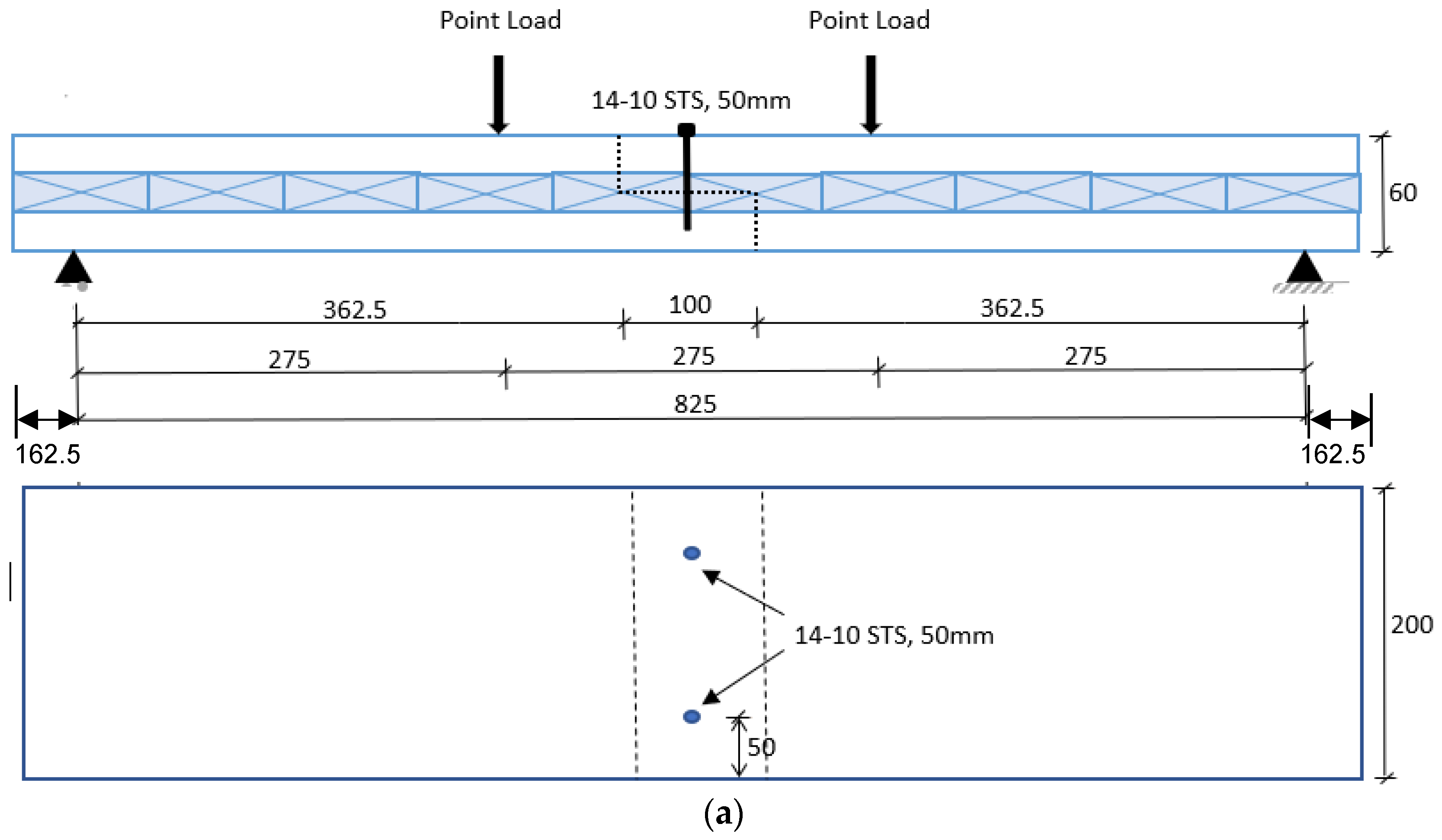
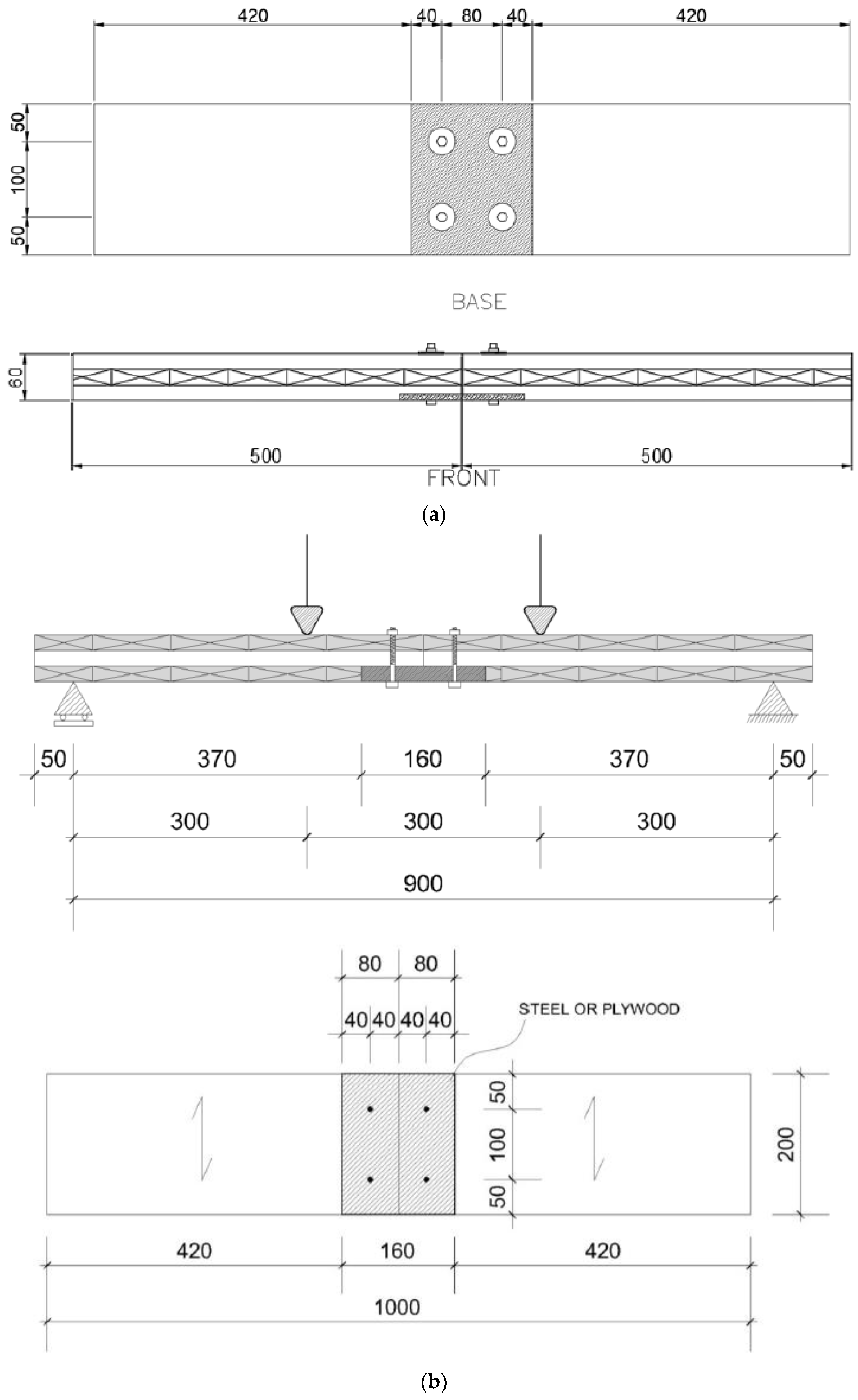
2.1. Configuration of the Connection Systems

Three-ply CLT specimens, manufactured using Norway spruce (Picea abies) and supplied by Stora Enso, were used in this study. The lamella thickness of each ply was 20 mm, which resulted in a total thickness of 60 mm. Figure 1 shows a diagram of the four-point bending test set-up for the half-lap CLT connection. To examine the influence of fasteners on the lap connection, two separate sets of fasteners, such as self-tapping screws (STS) of Ø14 mm, and bolts of Ø8 mm with washers were used to prepare the connections. STS were inserted up to a depth of 50 mm into the CLT member, resulting in a 20 mm penetration into the lower lap, as shown in Figure 1a. STS was installed using a handheld drilling machine and the minimum edge distance was maintained following the AS 1720.1 [28].
To facilitate bolt installation, all CLT panels were pre-drilled at a diameter of 1 mm in excess of the major bolt diameter to be used. The bolts in conjunction with washers were installed up to the total thickness of the CLT specimens. Moreover, to investigate the influence of lap length on the connection properties, two different lap lengths, namely 75 and 100 mm, were used for both STS and bolt connections.
Figure 2 demonstrates a spline connection system used in the study. Splines were bolt-connected to the bottom face of the CLT specimens only. To make the single spline connections, three different types of splines, e.g., steel plates with a thickness of 3 and 8 mm, and plywood plates with a thickness of 17 mm, were selected. A total of 4 bolts were installed on each plate. The plywood plates were connected to CLT members in two ways: (i) with bolts only and (ii) glue plus bolts. Two separate bolt diameters (6 and 8 mm) were used to investigate the effect of bolt diameter on the performance of connections. Bolts were installed in the spline connection in the same manner as were for the lap connection.
Table 1 presents the details of the test matrix considered in the current study. A total of 11 variations of CLT connections comprising lap and spline were tested, where 4 were related to lap connection and 7 were part of spline connection. For each variation of the connection, at least three samples were tested. Moreover, flexural capacities of spline connections along both the major and minor axis of the CLT specimen were tested, as shown in Figure 2a,b.

2.2. Material Properties of the Elements

2.2.1. CLT Panel

According to the European Standard EN338 [29], the grade of each lamella of the CLT panels used in this study was C24. The original dimensions of the CLT panels were 60 mm × 1450 mm × 1500 mm. Formaldehyde-free adhesives were used for finger jointing and surface bonding, but the narrow faces of the lamella were not bonded. The characteristic density of the specimen was 470 kg/m3. Before starting the experiment, the moisture content of the samples was measured using a handheld Crommelin moisture meter. Most of the samples’ moisture content remained within the range of 5–7%. The lower moisture content can be attributed to the low humidity during the dry season when samples were prepared for testing. Table 2 lists the mechanical properties of the lamellas obtained from the manufacturer’s datasheet.

2.2.2. Plywood

The plywood used in this study was manufactured by Specrite Formply using hardwood (Eucalyptus) veneers, which are typically more than 900 kg/m3 in density. The veneers were glued using phenol-formaldehyde. According to the Australian Standards AS1720 [28], the strength grade of the veneers is F17. The mechanical properties of the F17 grade are presented in Table 3.

2.2.3. Steel Plate, Bolts, and STS

Heavy-duty 14-10 self-tapping screws (STS), made from hardened carbon steel, were used to prepare the lap connection. The characteristic yield and tensile strength of the STS were 350 and 550 MPa, respectively. The yield and the ultimate strength of the steel plates used in the spline connections were 250 and 410 MPa, respectively. According to AS4100 [30], high-strength bolts (grade 8.8) were used for both lap and spline connections. The yield and the tensile strength of grade 8.8 high strength bolts were 600 and 830 MPa, respectively.

2.2.4. Testing Details

Four-point bending tests on CLT connections were conducted following the AS/NZS 4063.1 [31]. The connections, whether lap or spline, were positioned in the central uniform moment zone to ensure the fasteners and the connection arrangement were subjected to pure flexural stress, as shown in Figure 3. A universal testing machine with a capacity of 500 kN was used to apply the load and deflection values under the loading points were recorded. The load was applied at a rate of 2 mm/min in a displacement control mode. Metal bearing plates were placed between the supports and test samples and at the point of load to prevent bearing failure.

3. Results and Discussion

The bending resistance of connections in terms of moment capacity, support rotation, rotational rigidity, and rotational ductility was investigated for each test and is detailed in the subsequent sections.

3.1. Ultimate Moment and Angle of Support Rotation

The ultimate bending moment was calculated using Equation (1), where P is the applied load on each point and D is the total thickness of the specimen.
M u = 6 P D
To calculate the angle of rotation at the support of the CLT specimens, displacements at the loading points were recorded. Using these displacement values and span length, support rotation was calculated based on simple trigonometric principles, as shown in Equation (2). A similar approach to obtaining rotational capacity was adopted in previous research conducted on lap connections and dovetail connections of glulam beams [20]. Since the angle of rotation at the support is assumed to be very small, the small-angle approximations theory was used to determine the support rotation values. Hence, the support rotation angle was taken as the ratio of deflection and shear span length.
θ s u p p o r t = t a n 1 ( δ L o a d   p o i n t 6 D ) δ L o a d   p o i n t / ( 6 D )
where θsupport is the support rotation in radian, δLoad point is the displacement of specimen at loading point in millimeters and 6D represents the shear span length in millimeters, as shown in Figure 3.
Table 4 shows the mean and characteristic values of the ultimate moment capacity of the connections and the corresponding angle of rotations at the supports of the CLT members. Following the guidelines of the EN 14358-16 [32], the characteristic values of the resistance properties of the connections were determined based on the fifth percentile in the normal distribution corresponding to the sample size = 3 at a confidence level of 75 %.
Regardless of the fastener types, the connection with a 100 mm lap length performed better than that with a 75 mm lap length. Additionally, irrespective of lap length, bolted lap connections showed higher moment capacities than the screwed lap connections. For the single-spline connection, the CLT panel with a 3 mm-thick steel spline and Ø8 mm bolt had a higher moment capacity than the other spline connections when tested along the major axis. Bolt diameter played an important role in the moment capacity of the splined connection. Compared to the Ø6 mm bolted-spline connection, the Ø8 mm bolted-spline connection performed better. The effect of lap length and change in bolt diameter on the moment capacity is significant, but the effect of steel plate thickness on the moment capacity was found to be minimal. A thinner steel plate was found to be more beneficial, since it can bend as the moment increases. The thicker steel plate was too rigid, resulting in local bearing failure, clearly highlighting the significance of compatibility among connecting elements to act in unison when resisting external stresses.
While comparing the effect of the spline plate, it is evident that the unglued plywood plate was more flexible, leading to higher ultimate moment capacity. The steel plate increased the ultimate moment capacity but reduced the flexibility (support rotation) to some extent. Overall, compared to the lap connection, the spline connection exhibited higher moment capacity and experienced greater support rotation.

3.2. Rotational Rigidity and Ductility

Rotational rigidity, denoted as Rj, is determined from the slope of the moment–rotation curves. To determine Rj, simplified moment–rotation curves were used. Trilinear curves were drawn on the moment–rotation curves, as shown in Figure 4. Points P0 to P1 are linked by the first linear curve, points P1 to P2 are connected by the second, and points P2 to P3 are joined by the third linear curve. The rotational rigidity of the connection of the CLT specimen is here defined by the slope of the line between points P0 and P2 [33]. The rotational ductility of the CLT connection was determined using Equation (3), as outlined in Eurocode 5.
μ χ = χ u χ e
where μ χ = rotational ductility, χ u = ultimate rotation and χ e = elastic rotation.
Table 5 presents the mean and characteristic values of rotational rigidity and ductility of the splice connections of the considered CLT specimens. It was observed that the rotational rigidity and ductility of the lap connection increase with lap length. The screwed lap connections exhibited higher rigidity but less ductility compared to those of bolted lap connections. The Ø6 mm bolted-spline connections with a 3 mm-thick steel plate showed the highest rigidity compared to other spline connections when tested along the major axis. Bolt diameters influenced the rigidity and ductility of connections. The Ø6 mm bolts performed better than the Ø8 mm bolts in terms of rotational rigidity and ductility. The axis of loading also has a significant effect. As expected, the spline connections tested along the minor axis showed less rigidity and ductility compared to those tested along the major axis. Overall, the spline connections showed better performance in terms of rotational rigidity and ductility compared to the lap connection investigated. It is also evident that the use of a steel plate in the spline connection instead of plywood did not significantly affect the connection’s rigidity, although the ductility of the connection increased by a considerable margin.

3.3. Effect of Lap Lengths on the Half-Lapped Connections

The failure modes for both bolted and screwed lap connections are presented in Figure 5a,b, respectively. The failure occurred due to the fracture of the CLT specimen for both bolted and screwed lap connections.
Figure 6 and Figure 7 present the moment vs. support rotation behaviors of bolted and screwed lap connections with different lap lengths, respectively. Based on the characteristic values of the moment capacity, the bolted and screwed lap connections with a 100 mm lap length showed 39% and 33% higher moment capacity than that with a 75 mm lap length, respectively. This implies that the half-lap connections with longer lap lengths, whether STS- or bolt-connected, may offer higher ultimate moment capacity than the connections with smaller lap lengths. Additionally, the improvement in the bolted connection for increased lap length was significantly higher than the same in the STS-based connection. Therefore, lap length is an important parameter that should be considered for bolt connection.
Plastic or non-linear deformations before peak capacity were observed for the bolted lap connections, whereas the screwed lap connections exhibited relatively linear behaviour until they reached the ultimate moment capacity. The screwed lap connections seemed to retain their moment capacity after post-peak, showing a gradual decrease in resistance, as shown in Figure 7, but bolted connections showed a sudden drop after reaching peak moment as shown in Figure 6. In brief, CLT panels can be significantly degraded when connections are prepared using STS; consequently, CLT could lose strength substantially and the energy dissipation capacity of CLT connection may also be affected.
Figure 8a presents the characteristic ultimate moment and the corresponding characteristic support rotation values, and Figure 8b shows the characteristic rotational rigidity and ductility for various lap connections. The ultimate moment capacities of bolted lap connections with 100 and 75 mm lap lengths were about 2.18 and 2.40 times higher compared to their STS counterparts with 100 and 75 mm lap lengths, respectively. In the case of support rotation, this difference was even more significant. For bolted connections with 100 and 75 mm lap length, support rotations were approximately 5.35 and 5.13 times higher than those for STS connections, respectively. In contrast, the rotational rigidity of the STS connection was twice that of the bolted lap connections. Lower rotational rigidity and higher support rotation at the ultimate moment in bolted lap connections could be attributed to the use of washers. Using a washer increases the contact surface between the bolt head and the CLT panel, resulting in a reduction in bearing stress concentration. This eventually led to an increase in the ductility of the bolted lap connections, as the ductility of the bolted lap connection is found to be approximately 2.4 times higher than that of screwed lap connections.

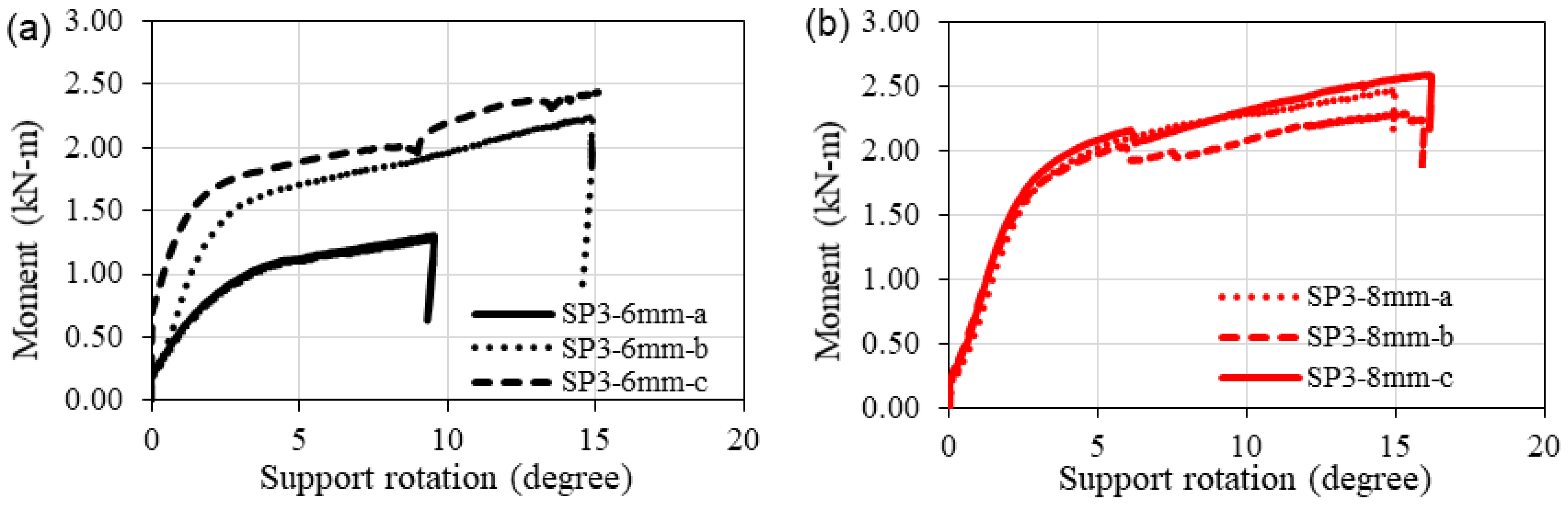
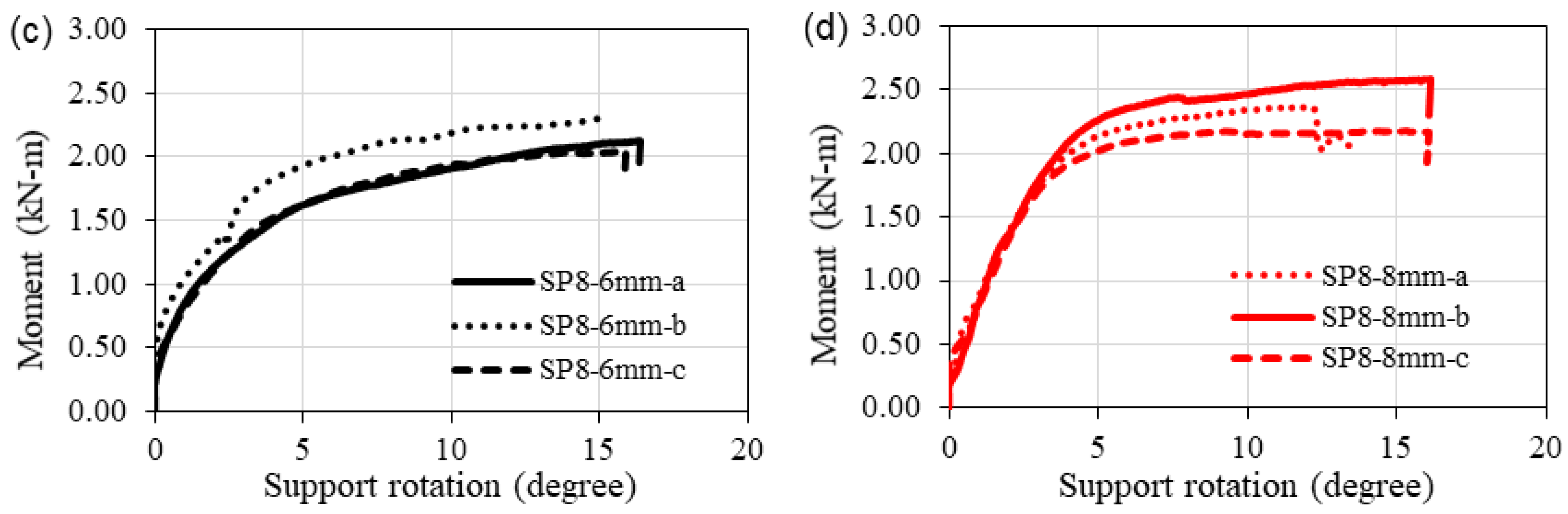
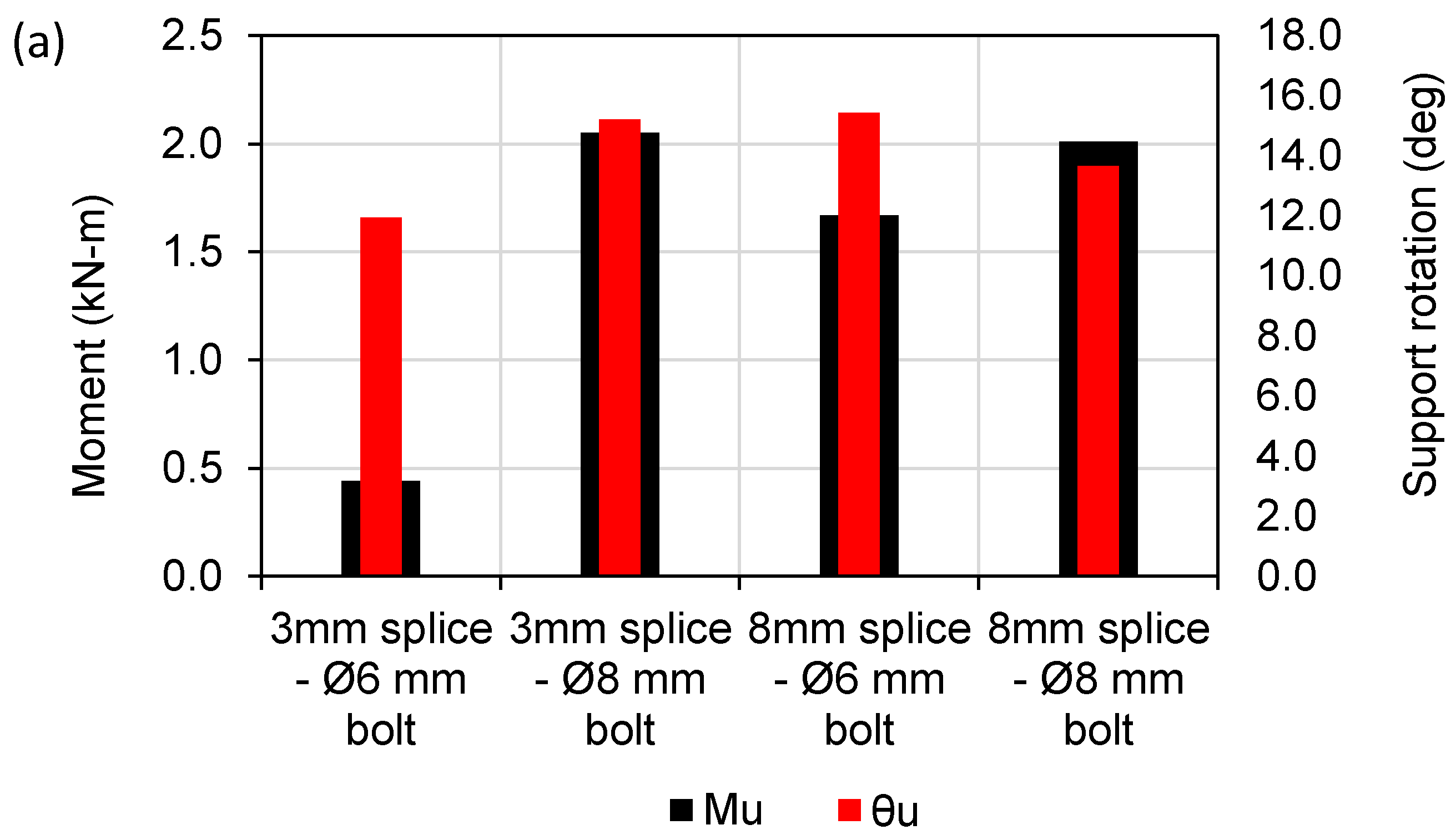
3.4. Effect of Steel Plates on the Behaviour of Bolted Spline Connections

The failure modes of the splined connections with 3 and 8 mm thick steel plates are shown in Figure 9a,b, respectively. The 3 mm steel spline bent due to the applied load, but the CLT panels remained unaffected. An opposite scenario was observed for the 8 mm steel spline plate, in which the steel spline was intact, but CLT panels failed at the contact surface, as discussed in Section 3.1.
Figure 10 depicts the moment–rotation performance of the half-spline connection with different thicknesses of steel plates and bolt diameters. In general, all moment–rotation curves demonstrated a sharp increase in the moment capacity in the elastic zone, followed by a smooth plastic curve until it reached the ultimate moment capacity. Beyond that, a sudden drop in the curve was observed, indicating the failure of the connection. The Ø8 mm bolted connections showed higher ultimate moment capacity than the Ø6 mm bolted connections for both the 3 and 8 mm steel spline, which can be seen in Figure 10. Support rotations at the ultimate moment for most of the considered spline connections were consistently close to 150, except for SP3-6 mm-a (Figure 10a) and SP8-8 mm-a (Figure 10d), which showed support rotations of 9.55° and 12.03° at the ultimate moment, respectively.
In the case of Ø6 mm bolts, it is observed that the increase in steel plate thickness from 3 to 8 mm resulted in approximately 3.80, 1.30 and 1.20 times higher ultimate moment, support rotation and rotational ductility, respectively. In contrast, the rotational rigidity was observed to be decreased by 5.40% due to this effect. The opposite scenario was observed for Ø8 mm bolts; as steel plate thickness was changed from 3 to 8 mm, the ultimate moment, support rotation and rotational ductility were reduced by 2, 10 and 34%, respectively. However, the rotational rigidity was found to be the same. It could be summarised that the thickness of steel spline may have a negligible effect on the capacity of bolted connection when subjected to bending loads, but an increase in bolt diameter could substantially enhance the capacity of the CLT connection.
Figure 11a, b presents the characteristic values of the key performance indicators of the bolted steel spline connections. For the splined connections with 3 mm steel plates, the Ø8 mm bolted connections showed 4.6 and 1.27 times higher ultimate moment and support rotation than those of Ø6 mm bolted connections. For the splined connections with 8 mm-thick steel plates, the Ø8 mm bolted connections showed 1.20 times higher ultimate moment capacity but 11.3% lower support rotation than those of Ø6 mm bolted connections. The rotational rigidity of the Ø8 mm bolted splined connections is 8.10% lower compared to that of the Ø6 mm bolted splined connections with 3 mm-thick steel plates. However, for the splined connections with 8 mm-thick steel plates, the rotational rigidity of both Ø6 mm and Ø8 mm bolted connections were found to be the same. In summary, although the Ø6 mm bolted spline connections performed better than the Ø8 mm bolted spline connections in terms of rotational ductility, an increase in bolt diameter seemed to increase moment capacity.

3.5. Effect of Axis Orientation on Spline Connections

Figure 12 presents the moment–rotation curves of the bolted spline connections used for CLT specimens tested along the major and the minor axis. The specimens being oriented about the major axis means that the outermost CLT layers are running parallel to the length of the specimen, whereas being centered around the minor axis indicates that the outer layers are perpendicular to the length of the connection. The connections of CLT specimens tested along the major axis demonstrated higher capacity compared to those oriented about the minor axis. This is obvious, as CLT has a higher load-carrying capacity along the major axis. Nonetheless, the performance of the connection system around the minor axis is not insignificant, as the difference in the ultimate moment capacity and rotation was only 7% and 8%, respectively, as shown in Figure 13a. The noticeable difference in the moment–rotation behaviour of the spline connection along the major vs. minor axes was due to the short elastic zone in the case of the minor axis specimens.
Figure 13b presents the rotational rigidity and ductility of the bolted spline connections tested along with the major and the minor axis. Numerically, the rotational rigidity for a major axis-oriented specimen is about 37% higher compared to a minor axis specimen. However, the opposite scenario was observed for rotational ductility; major axis-oriented specimens showed about 28% less ductility than minor axis-focused connections.

3.6. Influence of Spline Plate Types on Connections

The plywood spline connections tested in the current study were oriented about the minor axis only and hence, similar connections with different spline plates were compared with each other in this section. The failure modes of the various spline connections are shown in Figure 14. In the case of plywood spline connections, whether glued or not, the plywood layers were severely ruptured and failed. For steel spline connections, CLT failed due to bearing, but the steel splines remained unaffected under the loads.
The highest resistance against the bending moment was observed for the connection with a steel plate as a spline. When compared with the plywood spline specimen without glue, the steel spline specimen attained 24%, 4.54% and 72.90% higher moment capacity, rotational rigidity and ductility, respectively, as shown in Figure 15. However, the mean ultimate support rotation for the steel spline connection was 6% less than that of the plywood spline connection. Interestingly, the plywood connections without any glue performed better than their glued counterparts, as can be seen in Figure 16. The glued and bolted plywood spline connection exhibited 14% and 25% less ultimate moment and support rotation, respectively, than those for the bolted plywood spline connection without glue. Although gluing did not show any effect on the moment, rigidity, and rotational performance of the spline connection of CLTs, it enhanced the ductility of the connections by 26%, as depicted in Figure 15b. The reason for the higher ductility could be attributed to the stronger bond between CLT and plywood spline created by employing adhesion, which increased the overall ductility of the connection.

4. Summary and Conclusions

This experimental study demonstrates the performance of lap and spline connections of CLT members subjected to a bending moment. The influence of lap length and fastener types on lap connections was examined. Additionally, the effect of spline plate type and thickness and bolt diameter on the spline connections were investigated. The following specific conclusions are drawn from this study:
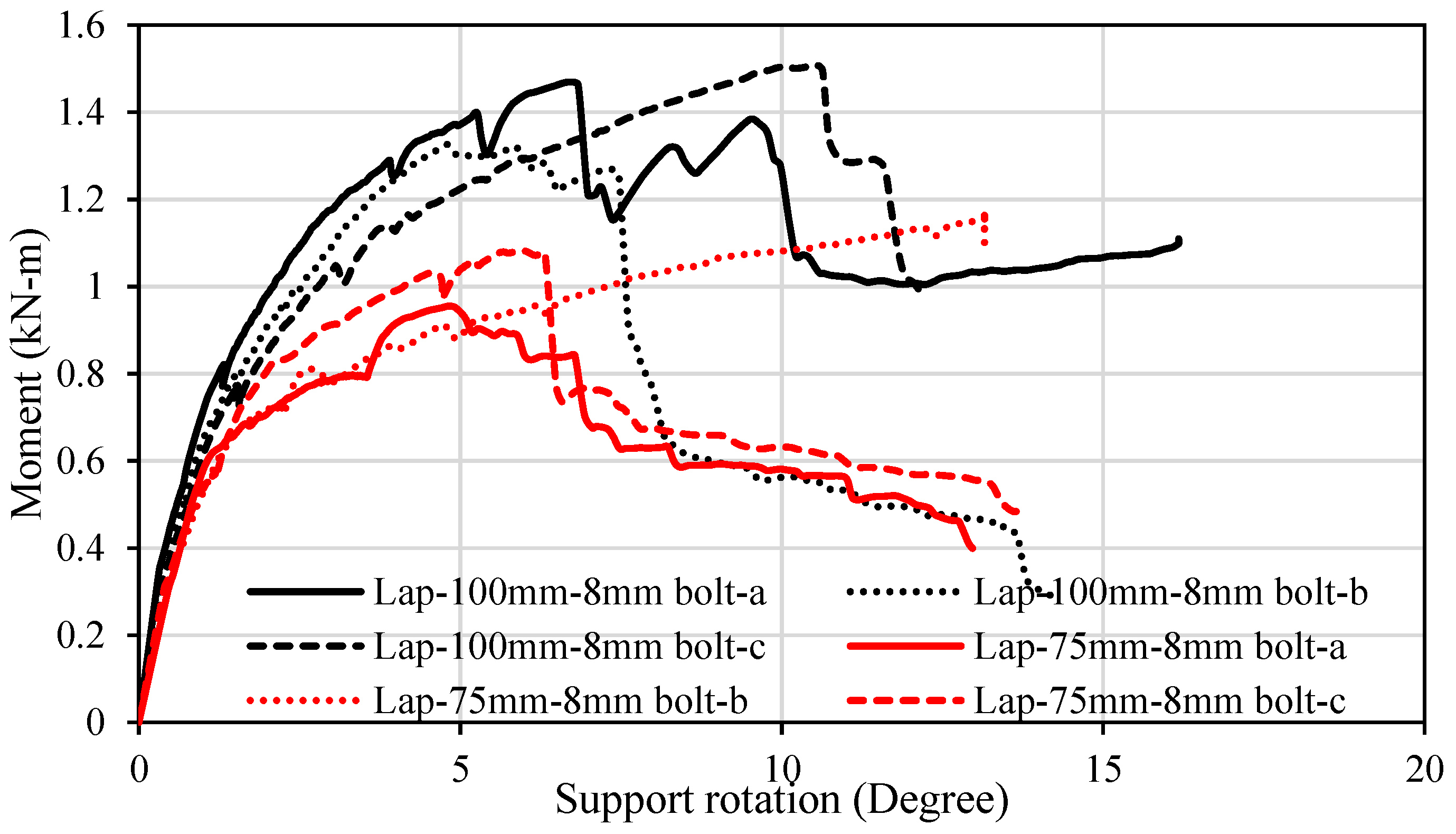
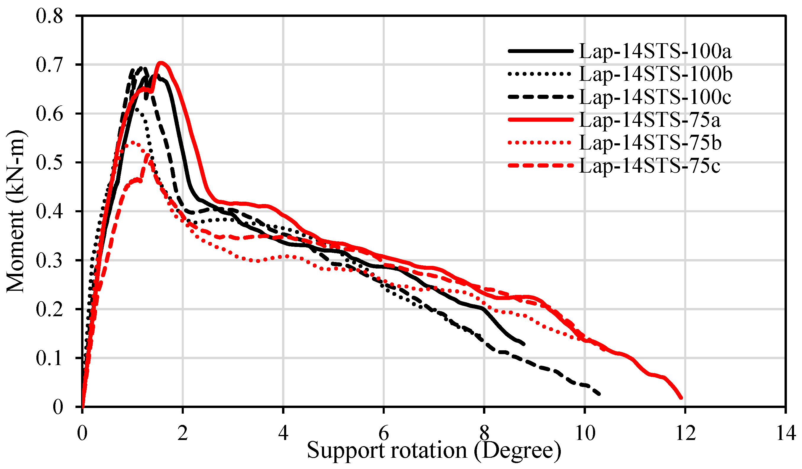
  • Compared to 75 mm lap length, a 100 mm lap length demonstrates 39% and 33% higher moment capacities for the bolted and screwed lap connections, respectively. Rotational rigidity and ductility of the lap connections also increase with the increase in the lap length. However, further investigation is recommended to determine an optimum lap length for the connections.
  • Plastic deformations were observed in bolted lap connections, whereas screwed lap connections exhibited relatively linear behaviour until they reached the ultimate moment capacity. Irrespective of lap lengths, the bolted lap connections showed better performance in terms of moment capacity, support rotation and ductility when compared to their counterpart (screwed lap) connections. In contrast, the rotational rigidity of screwed connections was observed to be higher than that of bolted lap connections.
  • The spline plate types showed a significant influence on the capacity of spline connections. The steel spline connection attained approximately 24%, 5% and 73% higher moment capacity, rotational rigidity and ductility, respectively, when compared to those for the plywood spline connection. However, the support rotation for the steel spline connection was found to be 6% less compared to that of the plywood spline connections.
  • An increase in bolt diameter increases moment capacity but decreases rotational rigidity when plate thickness is constant. The effect of an increase in the thickness of the steel spline on the capacities of the bolted steel spline connections subjected to bending moment is found to be insignificant.
  • The effect of glue on the bending moment, support rotation and rigidity of plywood spline connections was found to be negligible, as plywood spline connections without glue performed better. However, the application of glue along with bolts enhanced the ductility of the plywood spline connections by 26%.
  • The axis of loading (major axis vs. minor axis) is vital; connections tested along the minor axis showed less resistance to bending loads than the connections tested along the major axis. Nevertheless, the performance of the bolted spline connection system about the minor axis is not insignificant.
  • Overall, spline connections showed better performance in terms of moment capacity, support rotation, rotational rigidity and ductility compared to lap connections. The Ø8 mm bolt and 3 mm-thick steel spline were recognised as an optimum combination for the spline connections, as they showed the highest resistance to the bending moment.

Author Contributions

Conceptualization, M.S.; methodology, M.S. and M.A.-U.-S.; software, S.K.S.; validation, M.S., M.A.-U.-S., S.A.-D. and M.A.; formal analysis, S.K.S. and M.A.-U.-S.; investigation, S.K.S. and M.A.-U.-S.; writing—original draft preparation, S.K.S. and M.A.-U.-S.; writing—review and editing, S.A.-D., M.S. and M.A.-U.-S.; visualization, S.K.S. and M.A.-U.-S.; supervision, M.S.; project administration, M.S. All authors have read and agreed to the published version of the manuscript.

Funding

This research received no external funding.

Institutional Review Board Statement

Not applicable.

Informed Consent Statement

Not applicable.

Data Availability Statement

No further data is available.

Acknowledgments

The authors would like to thank John Paul Cabral, Alexander McIntyre, Murray Nagle and Tabata Correa for their contribution to this project. Additionally, the authors express their gratitude to Lube Veljanoski and Muhammad Ikramul Kabir for their generous support of this project.

Conflicts of Interest

The authors declare there is no conflict of interest.

References

  1. Jeleč, M.; Varevac, D.; Rajčić, V. Cross-laminated timber (CLT)—A state of the art report. Gradevinar 2018, 70, 2. [Google Scholar]
  2. Song, Y.-J.; Hong, S.-I. Compressive Strength Properties Perpendicular to the Grain of Larch Cross-laminated Timber. BioResources 2019, 14, 4304–4315. [Google Scholar]
  3. Bhat, J.A. Buckling behavior of cross laminated poplar timber columns using various performance improvement techniques. Mater. Today Proc. 2021, 44, 2792–2796. [Google Scholar] [CrossRef]
  4. Roensmaens, B.; Avez, C.; Van Parys, L.; Descamps, T. Refurbishment of Timber Floors with Screwed CLT Panels: Tests on Floor Elements and Connections. Int. J. Archit. Herit. 2021, 15, 334–348. [Google Scholar] [CrossRef]
  5. He, M.; Sun, X.; Li, Z. Bending and compressive properties of cross-laminated timber (CLT) panels made from Canadian hemlock. Constr. Build. Mater. 2018, 185, 175–183. [Google Scholar] [CrossRef]
  6. Roensmaens, B.; Van Parys, L.; Carpentier, O.; Descamps, T. Refurbishment of existing timber floors with screwed CLT panels. Int. J. Archit. Herit. 2018, 12, 622–631. [Google Scholar] [CrossRef]
  7. Humar, M.; Kržišnik, D.; Lesar, B.; Dujič, B. Monitoring a building made of CLT in Ljubljana. Wood Mater. Sci. Eng. 2020, 15, 335–342. [Google Scholar] [CrossRef]
  8. Pei, S.; Rammer, D.; Popovski, M.; Williamson, T.; Line, P.; van de Lindt, J.W. An overview of CLT research and implementation in North America. In Proceedings of the WCTE 2016, Vienna, Austria, 22–25 August 2016. [Google Scholar]
  9. Brandner, R.; Flatscher, G.; Ringhofer, A.; Schickhofer, G.; Thiel, A. Cross laminated timber (CLT): Overview and development. Eur. J. Wood Wood Prod. 2016, 74, 331–351. [Google Scholar] [CrossRef]
  10. O’Ceallaigh, C.; Harte, A.M. The elastic and ductile behaviour of CLT wall-floor connections and the influence of fastener length. Eng. Struct. 2019, 189, 319–331. [Google Scholar] [CrossRef]
  11. Taylor, B.; Barbosa, A.R.; Sinha, A. Cyclic performance of in-plane shear cross-laminated timber panel-to-panel surface spline connections. Eng. Struct. 2020, 218, 110726. [Google Scholar] [CrossRef]
  12. Izzi, M.; Casagrande, D.; Bezzi, S.; Pasca, D.; Follesa, M.; Tomasi, R. Seismic behaviour of Cross-Laminated Timber structures: A state-of-the-art review. Eng. Struct. 2018, 170, 42–52. [Google Scholar] [CrossRef]
  13. Ferk, H. Some building science aspects for building with CLT. In Focus Solid Timber Solutions-European Conference on Cross Laminated Timber (CLT); University of Bath: Bath, UK, 2013. [Google Scholar]
  14. Li, X.; Ashraf, M.; Subhani, M.; Kremer, P.; Li, H.; Anwar-Us-Saadat, M. Rolling shear properties of cross-laminated timber (CLT) made from Australian Radiata Pine–An experimental study. Structures 2021, 33, 423–432. [Google Scholar] [CrossRef]
  15. Rahman, M.; Ashraf, M.; Ghabraie, K.; Subhani, M. Evaluating timoshenko method for analyzing CLT under out-of-plane loading. Buildings 2020, 10, 184. [Google Scholar] [CrossRef]
  16. Li, X.; Ashraf, M.; Subhani, M.; Kremer, P.; Kafle, B.; Ghabraie, K. Experimental and numerical study on bending properties of heterogeneous lamella layups in cross laminated timber using Australian Radiata Pine. Constr. Build. Mater. 2020, 247, 118525. [Google Scholar] [CrossRef]
  17. Ettelaei, A.; Taoum, A.; Nolan, G. Rolling shear properties of cross-laminated timber made of fibre-managed plantation eucalyptus under short-span bending. Wood Mater. Sci. Eng. 2021, 1–8. [Google Scholar] [CrossRef]
  18. Sadeghi, M.; Ballerini, M.; Smith, I.; Pedrotti, E. Bending properties of connections in cross laminated timber. In IABSE Symposium Report; International Association for Bridge and Structural Engineering: Zurich, Switzerland, 2015. [Google Scholar]
  19. Gagnon, S.; Pirvu, C. CLT Handbook: Cross-Laminated Timber; FPInnovations: Pointe-Claire, QC, Canada, 2011. [Google Scholar]
  20. Li, H.; Lam, F.; Qiu, H. Comparison of glulam beam-to-beam connections with round dovetail and half-lap joints reinforced with self-tapping screws. Constr. Build. Mater. 2019, 227, 116437. [Google Scholar] [CrossRef]
  21. Muster, M.; Frangi, A. Experimental analysis and structural modelling of the punching behaviour of continuous two-way CLT flat slabs. Eng. Struct. 2020, 205, 110046. [Google Scholar] [CrossRef]
  22. Zarnani, P.; Quenneville, P. New design approach for controlling brittle failure modes of small-dowel-type connections in Cross-laminated Timber (CLT). Constr. Build. Mater. 2015, 100, 172–182. [Google Scholar] [CrossRef]
  23. Uibel, T.; Blaß, H.J. Load carrying capacity of joints with dowel type fasteners in solid wood panels. In Proceedings of the CIB-W18 Meeting, Florence, Italy, 28–31 August 2006. [Google Scholar]
  24. Uibel, T.; Blaß, H.J. Edge joints with dowel type fasteners in cross laminated timber. In Proceedings of the CIB-W18 Meeting, Bled, Slovenia, 28–31 August 2007. [Google Scholar]
  25. Tomasi, R.; Parisi, M.A.; Piazza, M. Ductile design of glued-laminated timber beams. Pract. Period. Struct. Des. Constr. 2009, 14, 113–122. [Google Scholar] [CrossRef]
  26. Hosseinzadeh, S.; Mohebby, B.; Elyasi, M. Bending performances and rolling shear strength of nail-cross-laminated timber. Wood Mater. Sci. Eng. 2020, 17, 113–120. [Google Scholar] [CrossRef]
  27. Zhang, S.; Chui, Y.H. Characterizing flexural behaviour of panel-to-panel connections in cross-laminated timber floor systems. Structures 2020, 28, 2047–2055. [Google Scholar] [CrossRef]
  28. AS 1720.1; Timber Structures Part 1, in Design Methods. Standards Australia: Sydney, Australia, 2010.
  29. EN 338: 2016; Structural Timber—Strength Classes. BSI Standards Publication: London, UK, 2016.
  30. AS 4100-1998 (R2016); Steelwork in Structures. SAI Global: Sydney, Australia, 1998.
  31. AS/NZS 4063.1; Characterization of Structural Timber. Standards Australia: Sydney, Australia, 2010.
  32. EN 14358: 2016; Timber Structures–Calculation and Verification of Characteristic Values. European Committee for Standardization: Brussels, Belgium, 2016.
  33. Subhani, M.; Globa, A.; Moloney, J. Timber-FRP composite beam subjected to negative bending. Struct. Eng. Mech. 2020, 73, 353–365. [Google Scholar]
Figure 1. Bending test on the half-lap CLT connection: (a) STS-connected and (b) bolt-connected.
Buildings 12 01124 g001aBuildings 12 01124 g001b
Figure 2. Bending test on single-splined CLT connection: (a) along the major axis and (b) along the minor axis.
Buildings 12 01124 g002
Figure 3. Four-point bending test setup used in the current study following AS/NZS 4063.1.
Buildings 12 01124 g003
Figure 4. The simplified tri-linear moment rotation curves of connections.
Buildings 12 01124 g004
Figure 5. Failure modes associated with (a) bolted and (b) screwed lap connections.
Buildings 12 01124 g005
Figure 6. Moment capacity vs. support rotation curves of the Ø8mm bolted lap connections with different lap lengths.
Buildings 12 01124 g006
Figure 7. Moment capacity vs. support rotation curves of the screwed lap connections with different lap lengths.
Buildings 12 01124 g007
Figure 8. Comparison among the lap connections based on the characteristic values of (a) moment capacities and support rotations and (b) rotational rigidity and ductility.
Buildings 12 01124 g008
Figure 9. Failure modes associated with (a) 3 mm- and (b) 8 mm-thick steel spline connections.
Buildings 12 01124 g009
Figure 10. Moment–rotation curves of various bolted steel spline connections: (a) 3 mm-thick steel plate with Ø6mm bolt, (b) 3 mm-thick steel plate with Ø8 mm bolt, (c) 8 mm-thick steel plate with Ø6 mm bolt and (d) 8 mm-thick steel plate with Ø8 mm bolt.
Buildings 12 01124 g010aBuildings 12 01124 g010b
Figure 11. Comparison among (a) bending moment and support rotation, (b) rotational rigidity and rotational ductility of steel spline connections with variation in steel plate thickness and bolt diameter.
Buildings 12 01124 g011aBuildings 12 01124 g011b
Figure 12. Moment vs. rotation curves for Ø8 mm bolted spline connections with a 8mm-thick steel plate when tested along the major and minor axes.
Buildings 12 01124 g012
Figure 13. Performance indicators including (a) moment and rotation relationship and (b) rotational rigidity and ductility behaviour of the bolted steel spline connections tested along the major and minor axes.
Buildings 12 01124 g013
Figure 14. Failure modes of (a) glued and bolted plywood, (b) unglued and bolted plywood and (c) 8mm-thick steel spline connection.
Buildings 12 01124 g014
Figure 15. Comparison of (a) moment–rotation and (b) rigidity and ductility of the spline connections with different spline plates tested along the minor axis.
Buildings 12 01124 g015
Figure 16. Moment–rotation curves of spline connections with different types of spline plates.
Buildings 12 01124 g016
Table 1. Detail of the test matrix used in this study.
Connection
Type
Variation in Lap/SplineNumber of
Samples
Fastener TypeSample Dimensions (L-W-D)Axis Orientation
Lap100 mm314-10 STS1150-200-60Major
75 mm3
100 mm3Bolt Ø8 mm
75 mm3
Spline3 mm steel spline3Bolt Ø8 mm1000-200-60Major
3 mm steel spline3Bolt Ø6 mm
8 mm steel spline3Bolt Ø8 mm
8 mm steel spline3Bolt Ø6 mm
17 mm plywood spline glued3Bolt Ø8 mm1000-200-60Minor
17 mm plywood spline3
8 mm steel spline3
Table 2. Mechanical properties of the lamellas as supplied by the manufacturer.
Properties of the Individual LamellaValues (MPa)
Modulus of elasticity parallel to the grain11,000
Modulus of elasticity perpendicular to the grain370
Rolling shear modulus72
Bending strength24
Tensile strength parallel to the grain14
Tensile strength perpendicular to the grain0.4
Compressive strength parallel to the grain21
Compressive strength perpendicular to the grain5.3
Rolling shear strength2.5
Table 3. The mechanical properties of the plywood used as a spline.
Properties of the PlywoodValues (MPa)
Modulus of elasticity parallel to the grain14,000
Modulus of rigidity930
Bending strength2.42
Tensile strength parallel to the grain25
Tensile strength perpendicular to the grain0.6
Compressive strength parallel to the grain34
Shear strength in the beam3.6
Table 4. The mean and characteristic values of the ultimate bending moments and support rotations of the CLT specimens.
Connection Type VariationsFastener TypeUltimate Bending Moment
Mu (kN-m)
The Angle of Rotation at the Support
θu (Degree)
MeanCOV
(%)
Character-istic ValuesMeanCOV
(%)
Character-istic Values
Lap 100 mm lap length14-10 STS0.665.80.541.2614.81.17
75 mm lap length14-10 STS0.5914.10.331.3015.31.21
100 mm lap lengthBolt Ø8 mm1.435.51.187.3432.66.21
75 mm lap lengthBolt Ø8 mm1.078.40.797.9946.16.26
SplineMajor
axis
3 mm steel splineBolt Ø8 mm2.455.22.0515.453.215.22
3 mm steel splineBolt Ø6 mm2.0024.80.4413.1519.411.95
8 mm steel splineBolt Ø8 mm2.385.02.0114.5112.313.67
8 mm steel splineBolt Ø6 mm2.167.21.6715.683.515.42
Minor
axis
17 mm plywood spline gluedBolt Ø8 mm1.309.00.9310.4825.49.23
17 mm plywood spline1.532.101.4314.091.513.99
8 mm steel spline2.018.41.4813.2512.112.49
Table 5. The mean and characteristic values of the rotational rigidity and ductility of all of the connections.
Connection Type VariationsFastener TypeRotational Rigidity
Rj (kN-m/deg)
Ductility
μ χ (deg/deg)
Mean COV
(%)
Characteristic ValuesMeanCOV
(%)
Characteristic Values
Lap 100 mm lap length14-10 STS0.6818.70.622.1614.22.02
75 mm lap length14-10 STS0.4931.00.422.0737.11.71
100 mm lap lengthBolt Ø8 mm0.3420.70.315.2718.14.82
75 mm lap lengthBolt Ø8 mm0.2641.10.214.5114.94.19
SplineMajor axis3 mm steel splineBolt Ø8 mm0.354.80.347.817.47.54
3 mm steel splineBolt Ø6 mm0.4535.90.378.4244.26.67
8 mm steel splineBolt Ø8 mm0.3716.90.345.3214.24.96
8 mm steel splineBolt Ø6 mm0.3712.30.358.9523.27.97
Minor axis17 mm plywood spline gluedBolt Ø8 mm0.184.20.185.4232.84.58
17 mm plywood spline0.228.90.213.951.43.92
8 mm steel spline0.2317.80.216.8347.75.30
Publisher’s Note: MDPI stays neutral with regard to jurisdictional claims in published maps and institutional affiliations.

