
Properties of Slag-Fly Ash Blended Geopolymer Concrete Reinforced with Hybrid Glass Fibers


Abstract
:1. Introduction
2. Materials and Methods
2.1. Materials
2.2. Mixture Proportioning
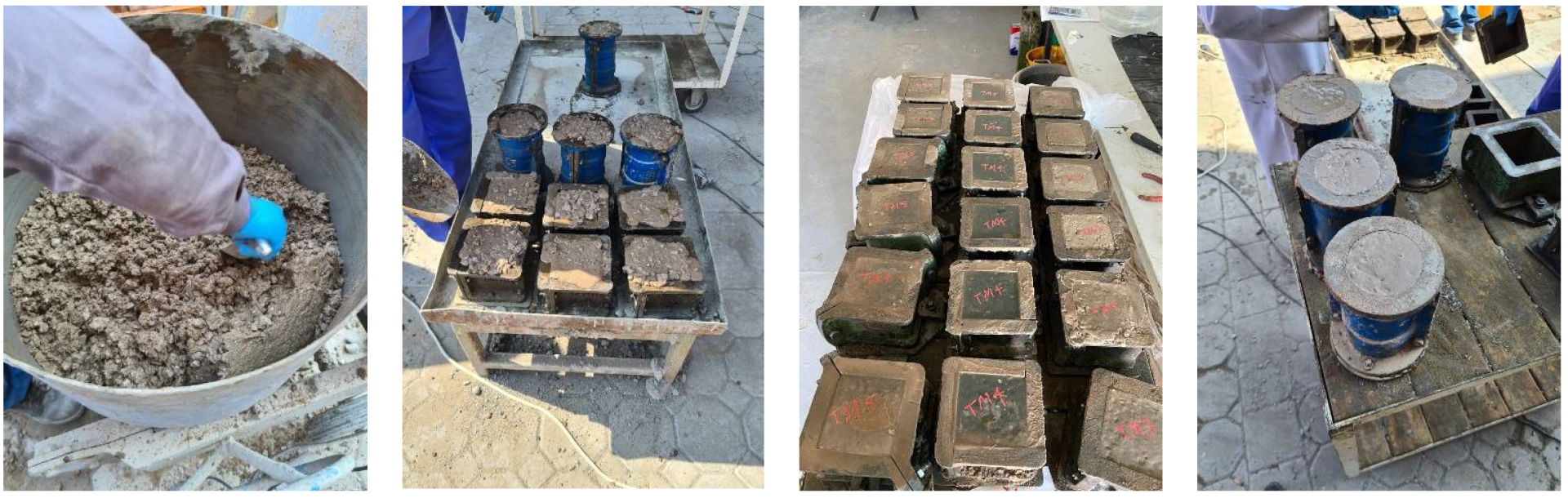
2.3. Sample Preparation
2.4. Performance Evaluation
2.4.1. Fresh and Physical Properties
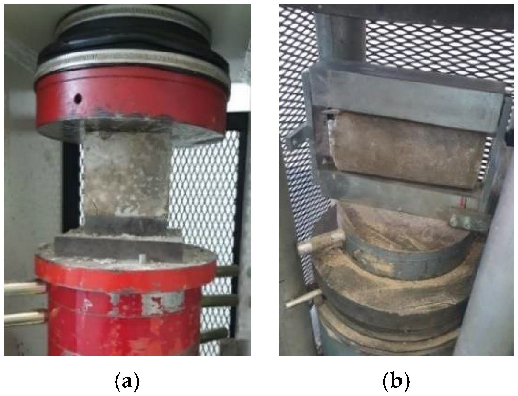
2.4.2. Mechanical Properties
2.4.3. Durability Properties
3. Experimental Results and Discussion
3.1. Slump
3.2. Compaction Factor
3.3. Vebe Time
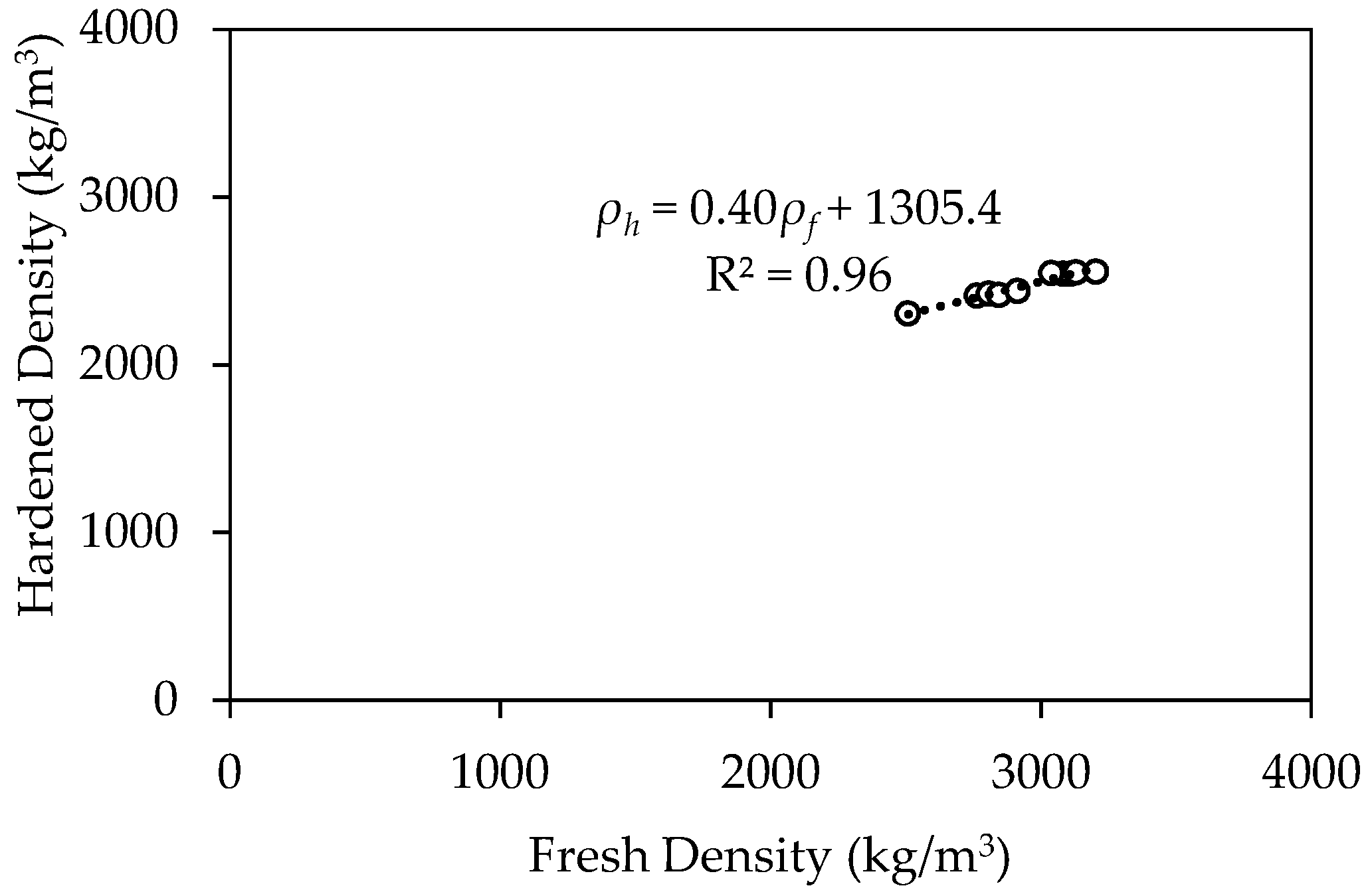
3.4. Fresh and Hardened Density
3.5. Compressive Strength
3.6. Compressive Stress–Strain Response
3.7. Modulus of Elasticity
3.8. Splitting Tensile Strength
3.9. Water Absorption
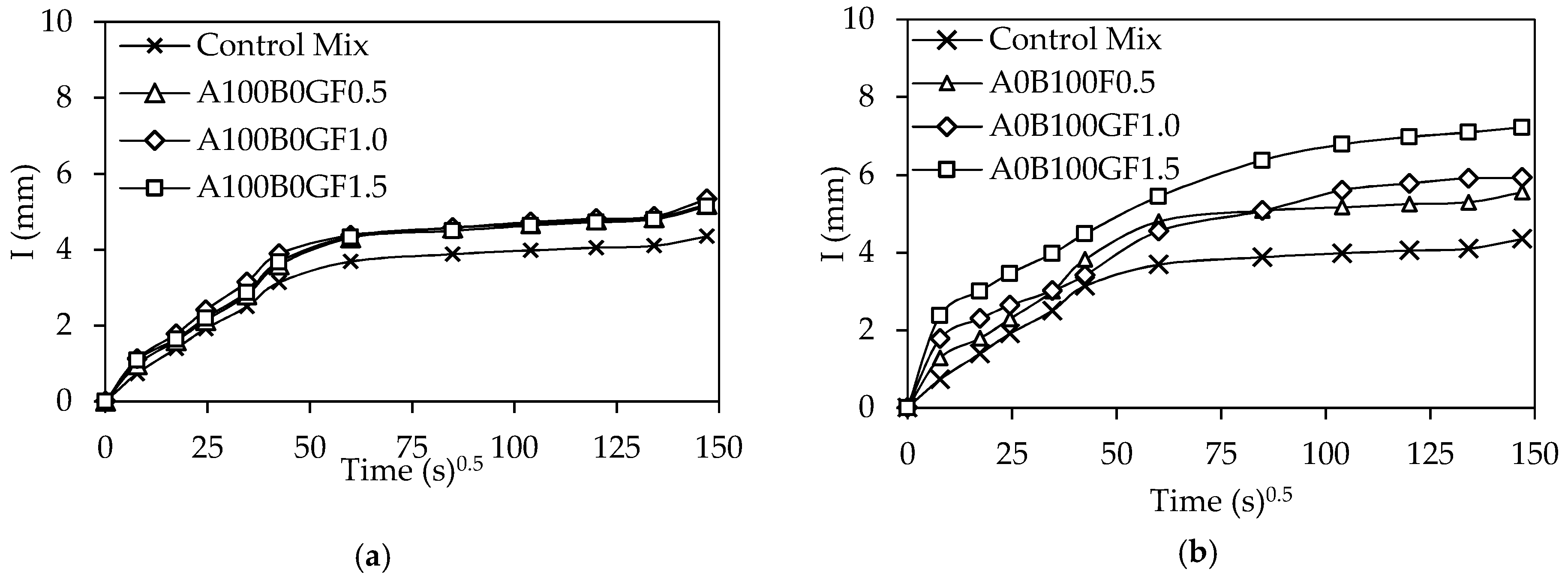
3.10. Sorptivity
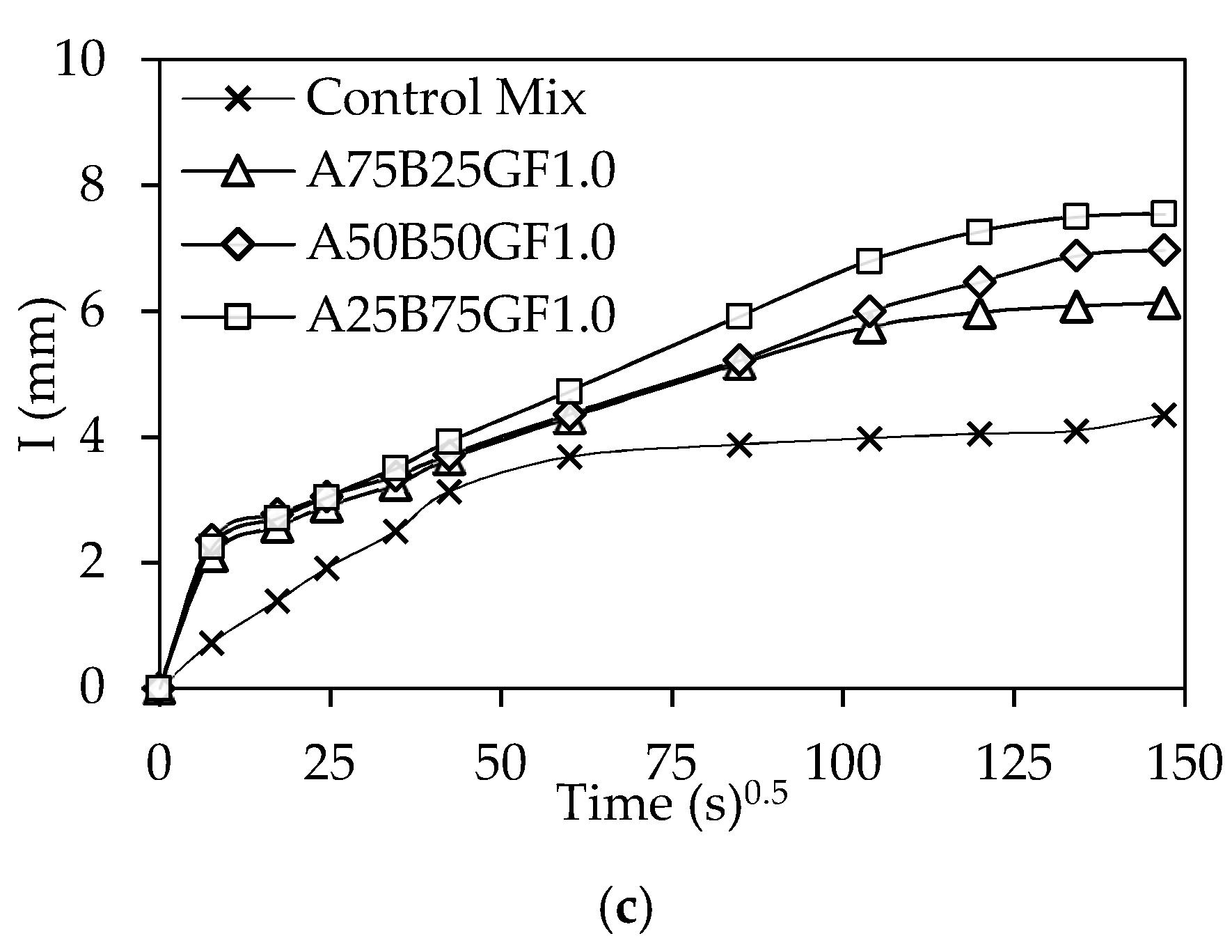
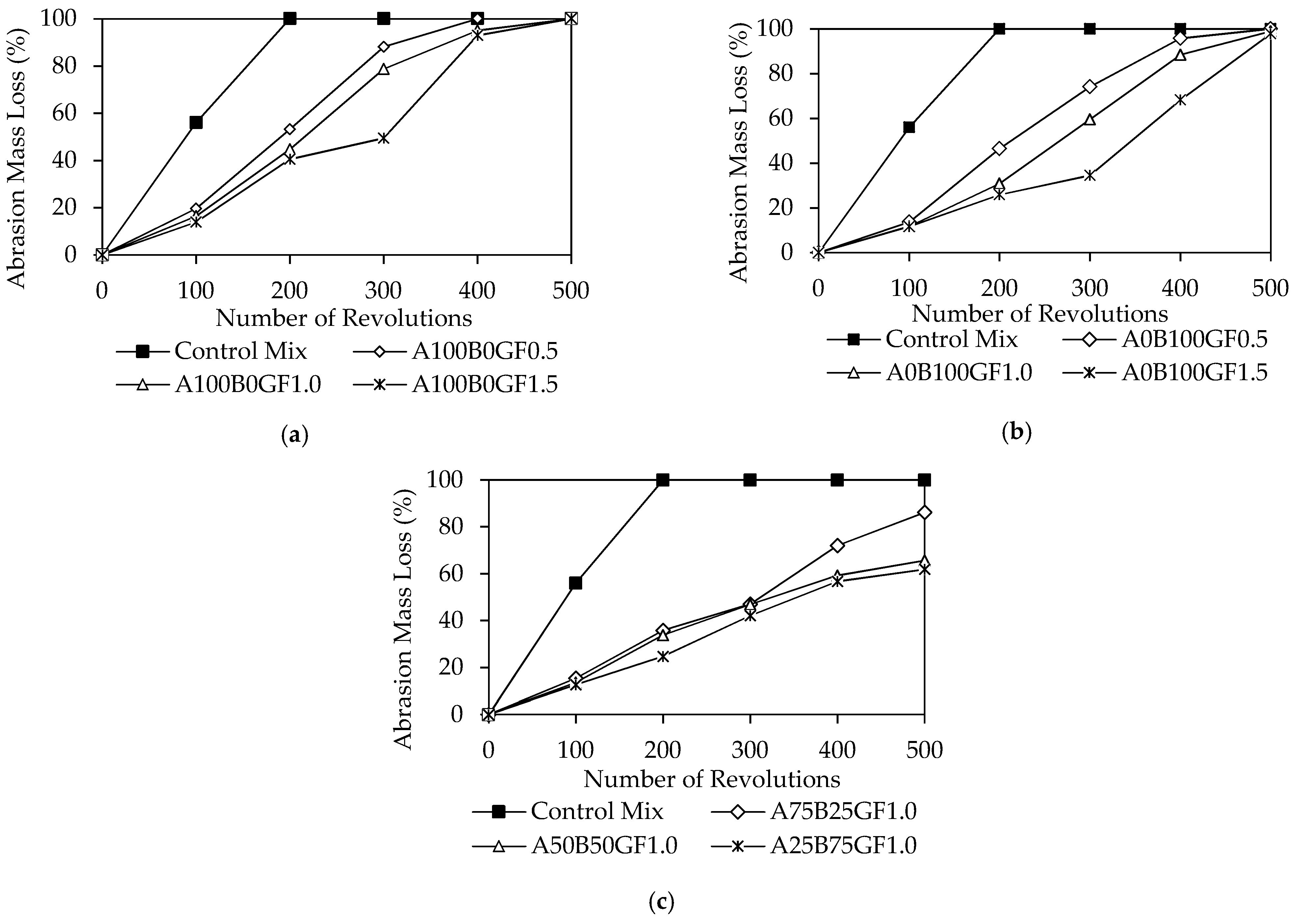
3.11. Abrasion Resistance
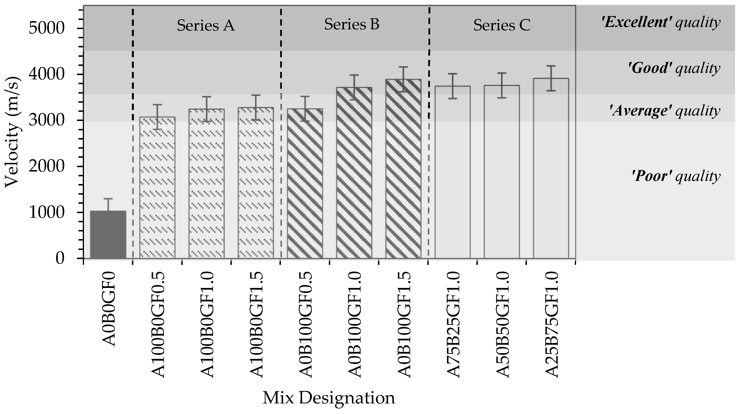
3.12. Ultrasonic Pulse Velocity
4. Conclusions
- The slump decreased by up to 75% as GF were added to the geopolymer concrete mix with a more drastic effect being noted with the addition of long GF. The incorporation of a hybrid GF combination at a 1% volume fraction led to better workability results, as it reduced the effect of fiber interlocking.
- Increasing the GF volume fraction and length led to up to 18% lower compaction factors and 43% higher vebe times than that of the plain concrete mix. Mixes with hybrid glass fiber combinations were better than those with a single type of GF.
- The addition of different types, volume fractions, and combinations of GF enhanced 1, 7, and 28-day compressive strengths of geopolymer concrete. Increasing the GF volume fraction resulted in a decrease in compressive strength development between 1 and 7 days with respect to the plain control mix. Mixes with a 1.5% long GF volume fraction resulted in the highest strength development at later ages. Hybrid GF-reinforced mixes exhibited larger strength development at an early age; however, increasing the amount of long GF in a hybrid combination delayed strength development.
- An increase of up to 24% in compressive strength was noted upon incorporating short GF in geopolymer concrete. The addition of long GF decreased the compressive strength up to 7 days but then increased it at 28 days. A significant increase of up to 40% in compressive strength was noted when incorporating hybrid GF combinations with more long GF at a 1% volume fraction.
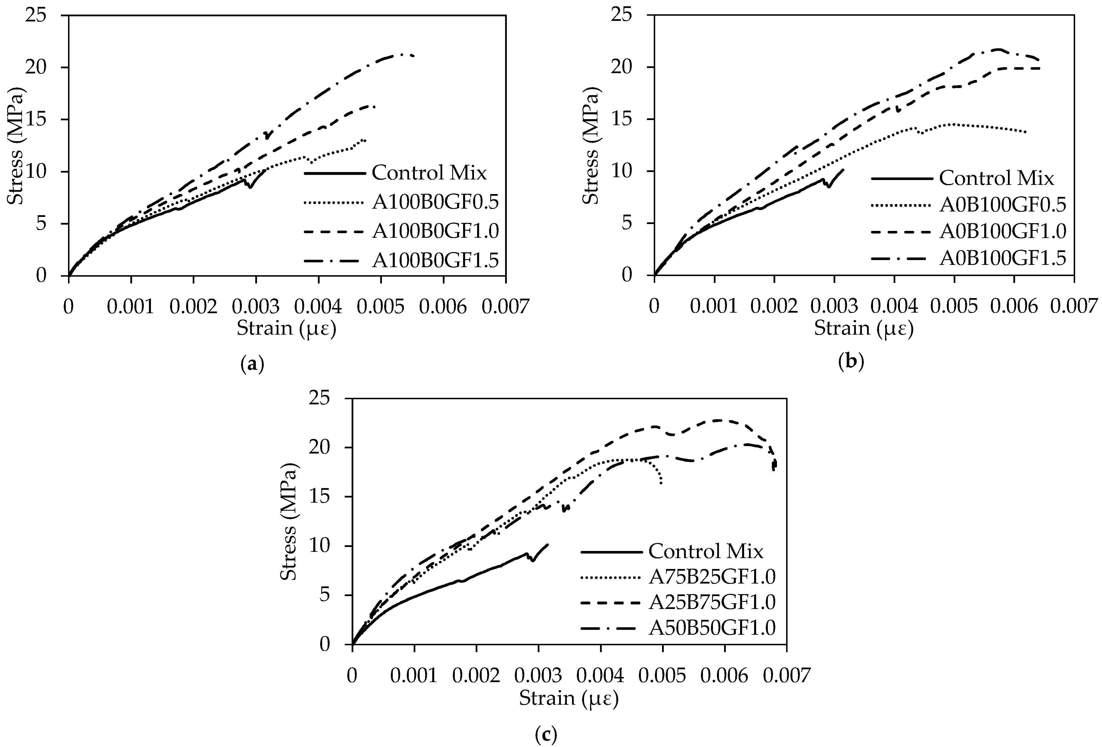
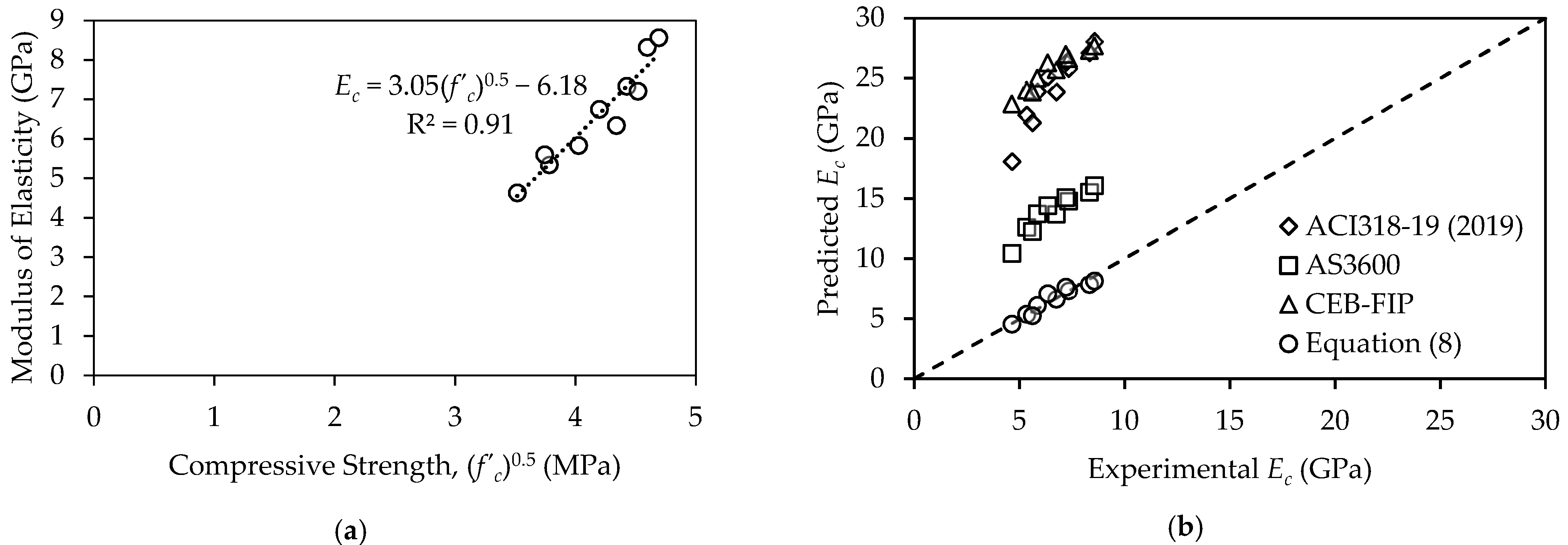
- The addition of glass fibers enhanced the peak stress and strain upon increasing the length and volume fraction of GF. Mixes with hybrid glass fiber combination at a ratio (A:B) of 1:1 and 1:3 at 1% volume fraction exhibited similar stress and strain of that mixed with long GF at 1.5%. The modulus of elasticity (Ec) was improved by up to 46% and 59% upon incorporating short and long GF, respectively. A further enhancement of 85% was noted when hybridizing GF.
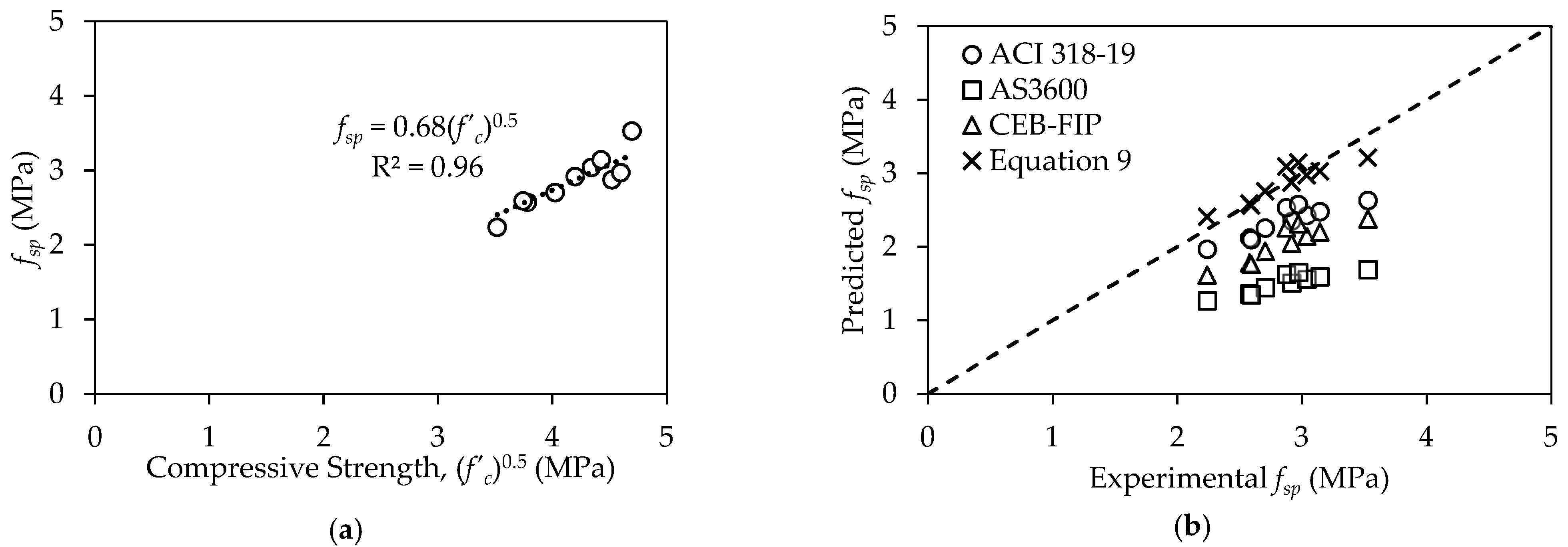
- The 28-day splitting tensile (fsp) strength increased by up to 30% and 41% with the inclusion of short and long GF, respectively. However, a hybrid mix with a proportion ratio (A:B) of 1:3 had a superior tensile strength of 3.5 MPa.
- The water absorption decreased by up to 34% with the addition of glass fibers with respect to the control mix. Incorporating a hybrid GF combination further decreased the water absorption by up to 42%. Contrarily, the initial sorptivity increased upon the addition of glass fibers, up to 67%. This is owed to the higher connectivity of voids and larger interfacial voids caused by glass fibers.
- The abrasion resistance of geopolymer concrete mixes was improved upon the inclusion of GF, more so for long GF than for short counterparts. Further enhancement was found in mixes with hybrid GF combinations at a 1% volume fraction.
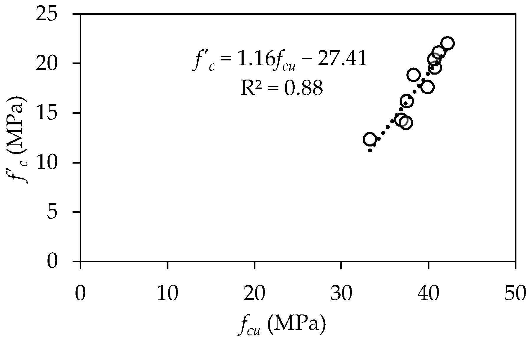
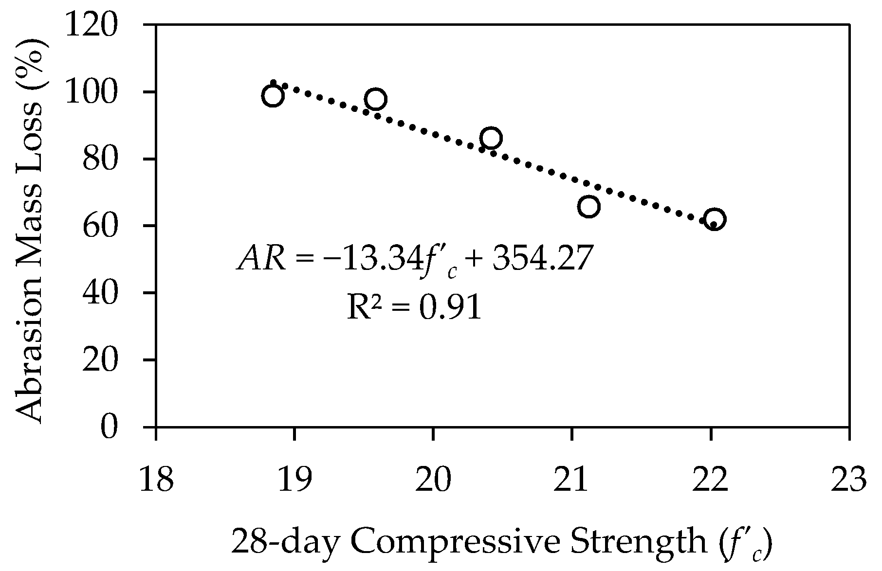
- Results of 28-day fcu were correlated to that of 28-day f’c. Correlation equations were also developed relating each of fsp, Ec, and abrasion resistance to 28-day f’c. Codified equations developed for plain cement-based concrete provided fewer representative results. The difference in concrete chemistry and the addition of fibers rendered these equations less accurate in predicting the properties of glass fiber-reinforced slag-fly ash geopolymer concrete.
- The use of GF enhanced the general quality of geopolymer concrete with up to 280% higher velocity values, according to the ultrasonic pulse velocity (UPV) test. While mixes reinforced with long GF and a high volume percentage (> 1%) or hybrid GF were classified as “good” quality, remaining mixes were categorized as “average.”
Author Contributions
Funding
Institutional Review Board Statement
Informed Consent Statement
Data Availability Statement
Conflicts of Interest
References
- Cement: Production Ranking Top Countries 2020. Statista. Available online: https://www.statista.com/statistics/267364/world-cement-production-by-country/ (accessed on 17 February 2022).
- Ma, C.-K.; Awang, A.Z.; Omar, W. Structural and material performance of geopolymer concrete: A review. Constr. Build. Mater. 2018, 186, 90–102. [Google Scholar] [CrossRef]
- Benhelal, E.; Zahedi, G.; Shamsaei, E.; Bahadori, A. Global strategies and potentials to curb CO2 emissions in cement industry. J. Clean. Prod. 2013, 51, 142–161. [Google Scholar] [CrossRef]
- Herzog, H.; Eliasson, B.; Kaarstad, O. Capturing Greenhouse Gases. Sci. Am. 2000, 282, 72–79. [Google Scholar] [CrossRef] [PubMed]
- Shaftel, H.; Callery, S.; Jackson, R.; Bailey, D. Overview: Weather, Global Warming and Climate Change. Climate Change: Vital Signs of the Planet. 2022. Available online: https://climate.nasa.gov/resources/global-warming-vs-climate-change (accessed on 12 February 2022).
- Smith, A.B. U.S. Billion-Dollar Weather and Climate Disasters, 1980–Present (NCEI Accession 0209268); NOAA National Centers for Environmental Information: Asheville, NC, USA, 2020. [Google Scholar] [CrossRef]
- Raza, A.; El Ouni, M.H.; Azab, M.; Ali, K.; Haider, H.; Rashedi, A. A scientometric review on mechanical and durability performance of geopolymer Paste: Effect of various raw materials. Constr. Build. Mater. 2022, 34, 128297. [Google Scholar] [CrossRef]
- El-Mir, A.; El-Hassan, H.; El-Dieb, A.; Alsallamin, A. Development and Optimization of Geopolymers Made with Desert Dune Sand and Blast Furnace Slag. Sustainability 2022, 14, 7845. [Google Scholar] [CrossRef]
- Najm, O.; El-Hassan, H.; El-Dieb, A. Optimization of alkali-activated ladle slag composites mix design using taguchi-based TOPSIS method. Constr. Build. Mater. 2022, 327, 126946. [Google Scholar] [CrossRef]
- El-Hassan, H.; Shehab, E.; Al-Sallamin, A. Effect of curing regime on the performance and microstructure characteristics of alkali-activated slag-fly ash blended concrete. J. Sustain. Cem. Mater. 2021, 10, 289–317. [Google Scholar] [CrossRef]
- El-Hassan, H.; Shehab, E.; Al-Sallamin, A. Influence of Different Curing Regimes on the Performance and Microstructure of Alkali-Activated Slag Concrete. J. Mater. Civ. Eng. 2018, 30, 04018230. [Google Scholar] [CrossRef]
- Baldovino, J.J.; Izzo, R.L.; Rose, J.L.; Domingos, M.D. Strength, durability, and microstructure of geopolymers based on recycled-glass powder waste and dolomitic lime for soil stabilization. Constr. Build. Mater. 2021, 271, 121874. [Google Scholar] [CrossRef]
- Consoli, N.C.; Silvano, L.W.; Lotero, A.; Filho, H.C.S.; Moncaleano, C.J.; Cristelo, N. Key parameters establishing alkali activation effects on stabilized rammed earth. Constr. Build. Mater. 2022, 345, 128299. [Google Scholar] [CrossRef]
- Davidovits, J. High-Alkali Cements for 21st Century Concretes. ACI Symp. Publ. 1994, 144, 383–398. [Google Scholar] [CrossRef]
- Aleem, M.I.A.; Arumairaj, P.D. Geopolymer Concrete—A review. Int. J. Eng. Sci. Emerg. Technol. 2012, 1, 118–122. [Google Scholar] [CrossRef]
- Allah, N.K.; El-Maaddawy, T.; El-Hassan, H. Geopolymer- and Cement-Based Fabric-Reinforced Matrix Composites for Shear Strengthening of Concrete Deep Beams: Laboratory Testing and Numerical Modeling. Buildings 2022, 12, 448. [Google Scholar] [CrossRef]
- Abu Obaida, F.; El-Maaddawy, T.; El-Hassan, H. Bond Behavior of Carbon Fabric-Reinforced Matrix Composites: Geopolymeric Matrix versus Cementitious Mortar. Buildings 2021, 11, 207. [Google Scholar] [CrossRef]
- Thomas, R.J.; Lezama, D.; Peethamparan, S. On drying shrinkage in alkali-activated concrete: Improving dimensional stability by aging or heat-curing. Cem. Concr. Res. 2017, 91, 13–23. [Google Scholar] [CrossRef] [Green Version]
- El Ouni, M.H.; Raza, A.; Haider, H.; Arshad, M.; Ali, B. Enhancement of mechanical and toughness properties of carbon fiber-reinforced geopolymer pastes comprising nano calcium oxide. J. Aust. Ceram. Soc. 2022, 1–13. [Google Scholar] [CrossRef]
- Raza, A.; Khan, Q.U.Z.; El Ouni, M.H.; Brahmia, A.; Berradia, M. Mechanical Performance of Geopolymer Composites Containing Nano-Silica and Micro-Carbon Fibers. Arab. J. Sci. Eng. 2022. [Google Scholar] [CrossRef]
- Rashedi, A.; Marzouki, R.; Raza, A.; Rawi, N.F.M.; Naveen, J. Mechanical, Fracture, and Microstructural Assessment of Carbon-Fiber-Reinforced Geopolymer Composites Containing Na2O. Polymers 2021, 13, 3852. [Google Scholar] [CrossRef]
- Ali, L.; El Ouni, M.H.; Raza, A.; Janjua, S.; Ahmad, Z.; Ali, B.; Ben Kahla, N.; Bai, Y. Experimental investigation on the mechanical and fracture evaluation of carbon Fiber-Reinforced cementitious composites with Nano-Calcium carbonate. Constr. Build. Mater. 2021, 308, 125095. [Google Scholar] [CrossRef]
- Medljy, J.; El-Hassan, H.; El-Maaddawy, T. Effect of Recycled Aggregate and Steel Fibers on the Mechanical Properties of Alkali-Activated Slag/Fly Ash Blended Concrete. ACI Symp. Publ. 2021, 349, 210–223. [Google Scholar] [CrossRef]
- El-Hassan, H.; Elkholy, S. Enhancing the performance of Alkali-Activated Slag-Fly ash blended concrete through hybrid steel fiber reinforcement. Constr. Build. Mater. 2021, 311, 125313. [Google Scholar] [CrossRef]
- El-Hassan, H.; Elkholy, S. Performance Evaluation and Microstructure Characterization of Steel Fiber–Reinforced Alkali-Activated Slag Concrete Incorporating Fly Ash. J. Mater. Civ. Eng. 2019, 31, 04019223. [Google Scholar] [CrossRef]
- Ravichandran, G.; Sivaraja, M.; Jegan, M.; Harihanandh, M.; Krishnaraja, A.R. Performance of Glass Fiber Reinforced Geopolymer Concrete under Varying Temperature Effect. Int. J. Civ. Eng. Technol. 2018, 9, 1316–1323. [Google Scholar]
- Sathanandam, T.; Awoyera, P.; Vijayan, V.; Sathishkumar, K. Low carbon building: Experimental insight on the use of fly ash and glass fibre for making geopolymer concrete. Sustain. Environ. Res. 2017, 27, 146–153. [Google Scholar] [CrossRef]
- Kumar, S.; Kumar, R.; Mehrotra, S.P. Influence of granulated blast furnace slag on the reaction, structure and properties of fly ash based geopolymer. J. Mater. Sci. 2010, 45, 607–615. [Google Scholar] [CrossRef]
- Lakshmi, K.; Rao, M.S.N. Experimental Study on Geopolymer Concrete by using Glass Fibers. Int. Res. J. Eng. Technol. 2019, 6, 1693–1698. [Google Scholar]
- Vijai, K.; Kumutha, R.; Vishnuram, B.G. Properties of Glass Fibre Reinforced Geopolymer Concrete Composites. Asian J. Civ. Eng. Build. Hous. 2012, 13, 511–520. [Google Scholar]
- ASTM C136/C136M-19; Standard Test Method for Sieve Analysis of Fine and Coarse Aggregates. ASTM International: West Conshohocken, PA, USA, 2019.
- ASTM C127-15; Standard Test Method for Relative Density (Specific Gravity) and Absorption of Coarse Aggregate. ASTM International: West Conshohocken, PA, USA, 2016.
- ASTM C29/C29M; Standard Test Method for Bulk Density (‘Unit Weight’) and Voids in Aggregate. ASTM International: West Conshohocken, PA, USA, 2017.
- ASTM C131-06; Standard Test Method for Resistance to Degradation of Small-Size Coarse Aggregate by Abrasion and Impact in the Los Angeles Machine. ASTM International: West Conshohocken, PA, USA, 2006.
- Aliabdo, A.A.; Abd Elmoaty, A.E.M.; Salem, H.A. Effect of water addition, plasticizer and alkaline solution constitution on fly ash based geopolymer concrete performance. Constr. Build. Mater. 2016, 121, 694–703. [Google Scholar] [CrossRef]
- El-Hassan, H.; Ismail, N. Effect of process parameters on the performance of fly ash/GGBS blended geopolymer composites. J. Sustain. Cem. Mater. 2017, 7, 122–140. [Google Scholar] [CrossRef]
- Reforcetech. 2022. Available online: https://reforcetech.com/ (accessed on 18 February 2022).
- Patankar, S.V.; Jamkar, S.S.; Ghugal, Y.M. Effect of Water-to-Geopolymer Binder Ratio on the Production of Fly ash Based Geopolymer Concrete. Int. J. Adv. Technol. Civ. Eng. 2012, 4, 15. [Google Scholar] [CrossRef]
- Vitola, L.; Pundiene, I.; Pranckeviciene, J.; Bajare, D. The Impact of the Amount of Water Used in Activation Solution and the Initial Temperature of Paste on the Rheological Behaviour and Structural Evolution of Metakaolin-Based Geopolymer Pastes. Sustainability 2020, 12, 8216. [Google Scholar] [CrossRef]
- Xie, J.; Kayali, O. Effect of Water Content on the Development of Fly Ash- based Geopolymers in Heat and Ambient Curing Conditions. Constr. Build. Mater. 2014, 67, 20–28. [Google Scholar] [CrossRef]
- Zuaiter, M.; El-Hassan, H.; El-Ariss, B.; El-Maaddawy, T. Early-age properties of slag-fly ash blended geopolymer concrete reinforced with glass fibers—A preliminary study. In Proceedings of the 7th World Congress on Civil, Structural, and Environmental Engineering (CSEE’22), Virtual Conference, 10–12 April 2022. [Google Scholar]
- ASTM C143/C143M—10; Standard Test Method for Slump of Hydraulic-Cement Concrete. ASTM International: West Conshohocken, PA, USA, 2010. [CrossRef]
- ASTM C138/C138; Standard Test Method for Density (Unit Weight), Yield, and Air Content (Gravimetric) of Concrete. ASTM International: West Conshohocken, PA, USA, 2017. [CrossRef]
- ASTM C642; Standard Test Method for Density, Absorption, and Voids in Hardened Concrete. ASTM International: West Conshohocken, PA, USA, 2013.
- BS 1881 Part:103; Testing Concrete. Part 103. Method for Determination of Compacting Factor. British Standards Institution: London, UK, 1993.
- BS EN 12350–1; Testing Fresh Concrete. Sampling and Common Apparatus. British Standards Institution: London, UK, 2019.
- BS EN 12390–3; Testing Hardened Concrete. Compressive Strength of Test Specimens. British Standards Institution: London, UK, 2009.
- ASTM C39; Standard Test Method for Compressive Strength of Cylindrical Concrete Specimens. ASTM International: West Conshohocken, PA, USA, 2015.
- ASTM C469; Standard Test Method for Static Modulus of Elasticity and Poisson’s Ratio of Concrete in Compression. ASTM International: West Conshohocken, PA, USA, 2014.
- ASTM C496; Standard Test Method for Splitting Tensile Strength of Cylindrical Concrete Specimens. ASTM International: West Conshohocken, PA, USA, 2011.
- ASTM C1585; Standard Test Method for Measurement of Rate of Absorption of Water by Hydraulic-Cement Concretes. ASTM International: West Conshohocken, PA, USA, 2013.
- Mehta, P.K.; Monteiro, P.J.M. Concrete: Microstructure, Properties, and Materials, 3rd ed.; McGraw-Hill: New York, NY, USA, 2006. [Google Scholar]
- C1747; Standard Test Method for Determining Potential Resistance to Degradation of Pervious Concrete by Impact and Abrasion. ASTM International: West Conshohocken, PA, USA, 2013.
- C597-02; Standard Test Method for Pulse Velocity Through Concrete. ASTM International: West Conshohocken, PA, USA, 2003.
- Saral, J.A.; Gayathri, S.; Tamilselvi, M.; Raj, B.R. An Experimental Study on Fibre Reinforced Geopolymer Concrete Composites- Glass Fibre, Copper Slag. Int. J. Eng. Technol. 2018, 7, 433–435. [Google Scholar] [CrossRef]
- Nematollahi, B.; Sanjayan, J.; Chai, J.X.H.; Lu, T.M. Properties of Fresh and Hardened Glass Fiber Reinforced Fly Ash Based Geopolymer Concrete. Key Eng. Mater. 2013, 594–595, 629–633. [Google Scholar] [CrossRef]
- Hu, C.-F.; Li, L.; Li, Z. Effect of fiber factor on the workability and mechanical properties of polyethylene fiber-reinforced high toughness geopolymers. Ceram. Int. 2021, 48, 10458–10471. [Google Scholar] [CrossRef]
- De Figueiredo, A.D.; Ceccato, M.R. Workability Analysis of Steel Fiber Reinforced Concrete Using Slump and Ve-Be Test. Mater. Res. 2015, 18, 1284–1290. [Google Scholar] [CrossRef] [Green Version]
- Kachouh, N.; El-Hassan, H.; El Maaddawy, T. Effect of steel fibers on the performance of concrete made with recycled concrete aggregates and dune sand. Constr. Build. Mater. 2019, 213, 348–359. [Google Scholar] [CrossRef]
- Larsen, I.L.; Thorstensen, R.T. The influence of steel fibres on compressive and tensile strength of ultra high performance concrete: A review. Constr. Build. Mater. 2020, 256, 119459. [Google Scholar] [CrossRef]
- Ismail, N.; El-Hassan, H. Development and Characterization of Fly Ash–Slag Blended Geopolymer Mortar and Lightweight Concrete. J. Mater. Civ. Eng. 2018, 30, 04018029. [Google Scholar] [CrossRef]
- Giridh, M.G.; Shetty, K.K.; Nayak, G. Synthesis of Fly-ash and Slag Based Geopolymer Concrete for Rigid Pavement. Mater. Today Proc. 2022, 60, 46–54. [Google Scholar] [CrossRef]
- Poornima, N.; Katyal, D.; Revathi, T.; Sivasakthi, M.; Jeyalakshmi, R. Effect of curing on mechanical strength and microstructure of fly ash blend GGBS geopolymer, Portland cement mortar and its behavior at elevated temperature. Mater. Today Proc. 2021, 47, 863–870. [Google Scholar] [CrossRef]
- Yip, C.K.; Lukey, G.C.; Van Deventer, J.S.J. The coexistence of geopolymeric gel and calcium silicate hydrate at the early stage of alkaline activation. Cem. Concr. Res. 2005, 35, 1688–1697. [Google Scholar] [CrossRef]
- El-Hassan, H.; Medljy, J.; El-Maaddawy, T. Properties of Steel Fiber-Reinforced Alkali-Activated Slag Concrete Made with Recycled Concrete Aggregates and Dune Sand. Sustainability 2021, 13, 8017. [Google Scholar] [CrossRef]
- El-Hassan, H.; Hussein, A.; Medljy, J.; El-Maaddawy, T. Performance of Steel Fiber-Reinforced Alkali-Activated Slag-Fly Ash Blended Concrete Incorporating Recycled Concrete Aggregates and Dune Sand. Buildings 2021, 11, 327. [Google Scholar] [CrossRef]
- Ganesan, V.; Ambily, P.S.; Ravi, R. Specimen Size Effect on Ultra High Strength Geopolymer Concrete (UHSGC). Int. J. Eng. Res. 2015, 3, 5. [Google Scholar]
- Bhargava, P.; Sharma, U.K.; Kaushik, S.K. Compressive Stress-Strain Behavior of Small Scale Steel Fibre Reinforced High Strength Concrete Cylinders. J. Adv. Concr. Technol. 2006, 4, 109–121. [Google Scholar] [CrossRef] [Green Version]
- Liao, W.-C.; Perceka, W.; Liu, E.-J. Compressive Stress-Strain Relationship of High Strength Steel Fiber Reinforced Concrete. J. Adv. Concr. Technol. 2015, 13, 379–392. [Google Scholar] [CrossRef] [Green Version]
- Yuan, X.; Guan, H.; Shi, Y. Stress-Strain Relationship of Steel Fiber Reinforced Alkali Activated Slag Concrete under Static Compression. Adv. Civ. Eng. 2021, 2021, 7951646. [Google Scholar] [CrossRef]
- ACI 318-19; Building code requirements for structural concrete (ACI 318-19): An ACI standard and commentary on building code requirements for structural concrete. American Concrete Institute: Farmington Hills, MI, USA, 2014.
- Comité Euro-International du Béton. CEB-FIB Model Code 1990 Design Code; Thomas Telford, Ltd.: London, UK, 1993. [Google Scholar]
- AS3600; Concrete Structures. Standards Australia: Sydney, Australia, 2009.
- Park, S.H.; Kim, D.J.; Ryu, G.S.; Koh, K.T. Tensile behavior of Ultra High Performance Hybrid Fiber Reinforced Concrete. Cem. Concr. Compos. 2012, 34, 172–184. [Google Scholar] [CrossRef]
- Chen, K.; Wu, D.; Xia, L.; Cai, Q.; Zhang, Z. Geopolymer concrete durability subjected to aggressive environments—A review of influence factors and comparison with ordinary Portland cement. Constr. Build. Mater. 2021, 279, 122496. [Google Scholar] [CrossRef]
- Ali, B.; Qureshi, L.A.; Shah, S.H.A.; Rehman, S.U.; Hussain, I.; Iqbal, M. A step towards durable, ductile and sustainable concrete: Simultaneous incorporation of recycled aggregates, glass fiber and fly ash. Constr. Build. Mater. 2020, 251, 118980. [Google Scholar] [CrossRef]
- Kwan, W.H.; Cheah, C.B.; Ramli, M.; Chang, K.Y. Alkali-resistant glass fiber reinforced high strength concrete in simulated aggressive environment. Mater. Constr. 2018, 68, 147. [Google Scholar] [CrossRef]
- Ghosh, R.; Sagar, S.P.; Kumar, A.; Gupta, S.K.; Kumar, S. Estimation of geopolymer concrete strength from ultrasonic pulse velocity (UPV) using high power pulser. J. Build. Eng. 2018, 16, 39–44. [Google Scholar] [CrossRef]
- BS 1881 Part:203; Specification for Testing Concrete.: Recommendations for Measurement of Velocity of Ultrasonic Pulses in Concrete. British Standards Institution: London, UK, 1986.


| Oxide Compound | Material (%) | ||
|---|---|---|---|
| Slag | Fly Ash | Dune Sand | |
| CaO | 42.0 | 3.3 | 14.1 |
| SiO2 | 34.7 | 48.0 | 64.9 |
| Al2O3 | 14.4 | 23.1 | 3.0 |
| MgO | 6.9 | 1.5 | 1.3 |
| Fe2O3 | 0.8 | 12.5 | 0.7 |
| Loss in ignition | 1.1 | 1.1 | 0.0 |
| Others | 1.1 | 10.5 | 16.0 |
| Physical Properties | |||
| Blaine fineness (cm2/g) | 4250 | 3680 | 117 |
| Uniformity coefficient | 2.86 | 9.10 | 1.47 |
| Curvature coefficient | 0.71 | 1.45 | 1.09 |
| Specific gravity | 2.70 | 2.32 | 2.77 |
| Physical Property, Unit | Standard Test | Value |
|---|---|---|
| Fineness modulus | [31] | 6.82 |
| Water absorption, % | [32] | 0.20 |
| Specific gravity | [33] | 2.82 |
| Dry-rodded density, kg/m3 | [33] | 1635 |
| Los Angeles abrasion, % | [34] | 16.0 |
| Specific surface area, cm2/g | [31] | 2.49 |
| Soundness (MgSO4), % | [34] | 1.20 |
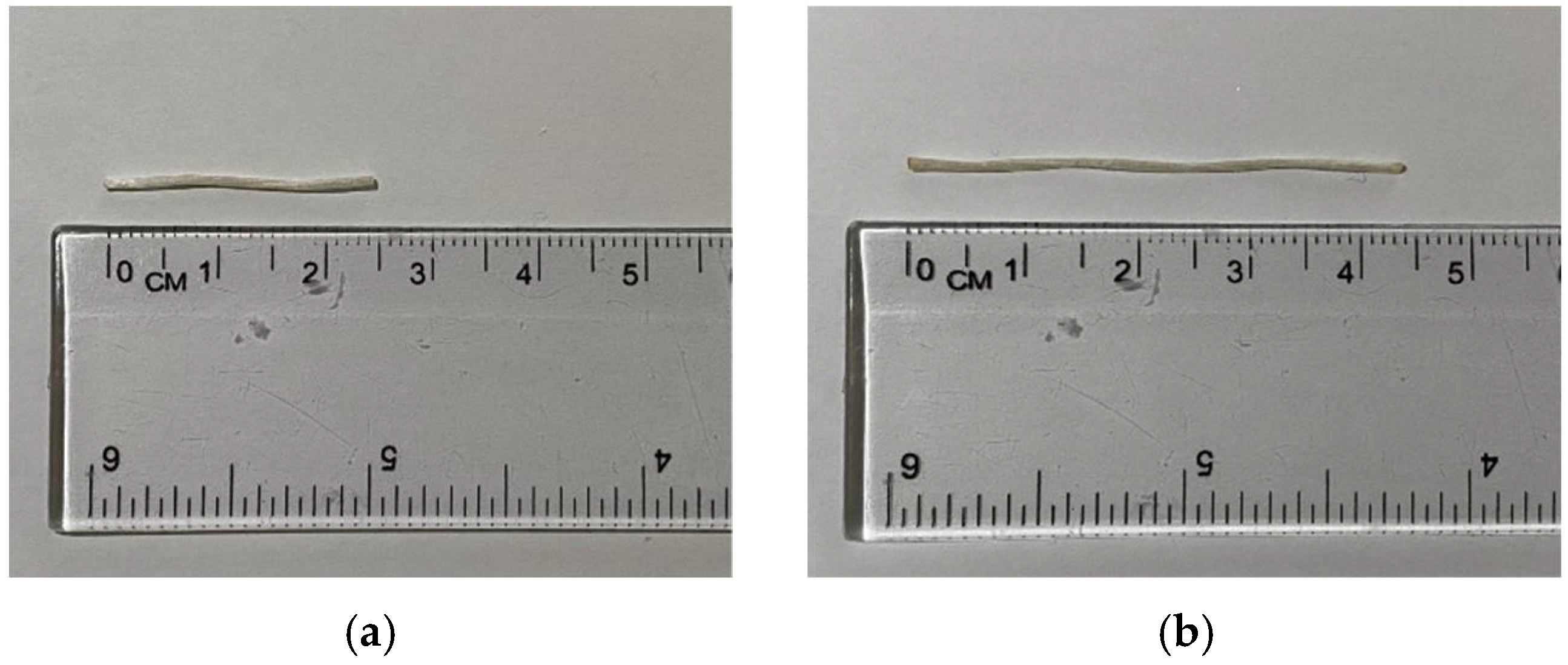
| Property, Unit | Type A | Type B |
|---|---|---|
| Length, mm | 24 | 43 |
| Diameter, mm | 0.7 | 0.7 |
| Aspect ratio | 35 | 62 |
| Tensile strength, MPa | >1000 | >1000 |
| Young’s modulus, GPa | 42 | 42 |
| Specific gravity | 2.0 | 2.0 |
| Group | Mix Designation | Binder | Dune Sand | Coarse Aggregates | AAS | SP | Water | Glass Fibers | |||
|---|---|---|---|---|---|---|---|---|---|---|---|
| Slag | Fly Ash | SS | SH | Proportions (A:B) | vf (%) | ||||||
| Control | A0B0GF0.0.0 | 225 | 75 | 725 | 1210 | 99 | 66 | 7.5 | 75 | 0:0 | 0.0 |
| A | A100B0GF0.5 | 225 | 75 | 725 | 1210 | 99 | 66 | 7.5 | 75 | 1:0 | 0.5 |
| A100B0GF1.0 | 225 | 75 | 725 | 1210 | 99 | 66 | 7.5 | 75 | 1:0 | 1.0 | |
| A100B0GF1.5 | 225 | 75 | 725 | 1210 | 99 | 66 | 7.5 | 75 | 1:0 | 1.5 | |
| B | A0B100GF0.5 | 225 | 75 | 725 | 1210 | 99 | 66 | 7.5 | 75 | 0:1 | 0.5 |
| A0B100GF1.0 | 225 | 75 | 725 | 1210 | 99 | 66 | 7.5 | 75 | 0:1 | 1.0 | |
| A0B100GF0.5 | 225 | 75 | 725 | 1210 | 99 | 66 | 7.5 | 75 | 0:1 | 1.5 | |
| C | A25B75GF1.0 | 225 | 75 | 725 | 1210 | 99 | 66 | 7.5 | 75 | 3:1 | 1.0 |
| A50B50GF1.0 | 225 | 75 | 725 | 1210 | 99 | 66 | 7.5 | 75 | 1:1 | 1.0 | |
| A75B25GF1.0 | 225 | 75 | 725 | 1210 | 99 | 66 | 7.5 | 75 | 1:3 | 1.0 | |
| Mix Designation | Slump (mm) | Change in Slump (%) * | Compaction Factor | Change in Compaction Factor (%) * | Vebe Time (sec) | Change in Vebe Time (%) * |
|---|---|---|---|---|---|---|
| A0B0GF0.0 | 160 | - | 0.94 | - | 3.5 | - |
| A100B0GF0.5 | 85 | −46.8 | 0.92 | −2.1 | 3.6 | 2.9 |
| A100B0GF1.0 | 80 | −50.0 | 0.90 | −4.3 | 3.7 | 5.7 |
| A100B0GF1.5 | 50 | −68.7 | 0.87 | −7.5 | 4.6 | 31.4 |
| A0B100GF0.5 | 75 | −53.1 | 0.86 | −8.5 | 4.0 | 14.3 |
| A0B100GF1.0 | 50 | −68.7 | 0.80 | −14.9 | 4.6 | 31.4 |
| A0B100GF1.5 | 40 | −75.0 | 0.77 | −18.1 | 5.0 | 42.9 |
| A75B25GF1.0 | 110 | −31.2 | 0.91 | −3.2 | 3.6 | 2.9 |
| A50B50GF1.0 | 100 | −37.5 | 0.88 | −6.4 | 4.2 | 20.0 |
| A25B75GF1.0 | 55 | −65.6 | 0.78 | −17.0 | 4.7 | 34.3 |
| Mix ID | Fresh Density (kg/m3) | Hardened Density (kg/m3) |
|---|---|---|
| A0B0GF0.0 | 2509 ± 126 | 2303 ± 116 |
| A100B0GF0.5 | 2765 ± 111 | 2410 ± 150 |
| A100B0GF1.0 | 2808 ± 169 | 2422 ± 146 |
| A100B0GF1.5 | 3084 ± 173 | 2541 ± 143 |
| A0B100GF0.5 | 2845 ± 200 | 2414 ± 169 |
| A0B100GF1.0 | 2915 ± 117 | 2439 ± 105 |
| A0B100GF1.5 | 3110 ± 187 | 2543 ± 153 |
| A75B25GF1.0 | 3039 ± 152 | 2545 ± 128 |
| A50B50GF1.0 | 3131 ± 220 | 2550 ± 179 |
| A25B75GF1.0 | 3205 ± 257 | 2554 ± 205 |
| Mix Designation | Compressive Strength, fcu (MPa) | Strength Development of fcu | f’c | fsp (MPa) | f’c/fcu | fsp/f’c | Ec (GPa) | |||
|---|---|---|---|---|---|---|---|---|---|---|
| 1-Day | 7-Day | 28-Day | 1d–7d (%) a | 7d–28d (%) b | ||||||
| A0B0GF0.0 | 23.2 ± 1.2 | 31.9 ± 0.9 | 33.3 ± 0.2 | 37.5 | 4.4 | 12.4 ± 1.2 | 2.2 ± 0.1 | 0.37 | 0.18 | 4.6 ± 0.2 |
| A100B0GF0.5 | 25.4 ± 1.4 | 33.6 ± 0.9 | 36.9 ± 1.1 | 32.3 | 9.8 | 14.3 ± 2.1 | 2.6 ± 0.1 | 0.39 | 0.18 | 5.4 ± 0.2 |
| A100B0GF1.0 | 26.2 ± 0.4 | 33.9 ± 1.1 | 37.5 ± 0.5 | 29.4 | 10.6 | 16.2 ± 1.5 | 2.8 ± 0.1 | 0.43 | 0.17 | 5.8 ± 0.2 |
| A100B0GF1.5 | 28.7 ± 0.9 | 37.4 ± 0.8 | 39.9 ± 1.6 | 30.3 | 6.7 | 17.6 ± 3.2 | 2.9 ± 0.2 | 0.44 | 0.17 | 6.8 ± 0.3 |
| A0B100GF0.5 | 25.8 ± 1.2 | 36.8 ± 3.1 | 37.4 ± 0.3 | 42.6 | 1.6 | 14.0 ± 0.9 | 2.6 ± 0.6 | 0.37 | 0.19 | 5.6 ± 0.6 |
| A0B100GF1.0 | 27.7 ± 0.3 | 37.7 ± 1.0 | 38.3 ± 2.4 | 36.1 | 1.6 | 18.9 ± 2.1 | 3.0 ± 0.1 | 0.49 | 0.16 | 6.3 ± 0.2 |
| A0B100GF1.5 | 29.1 ± 1.7 | 38.5 ± 2.5 | 40.7 ± 1.1 | 32.3 | 5.7 | 20.2 ± 3.9 | 3.2 ± 0.1 | 0.50 | 0.16 | 7.3 ± 0.2 |
| A75B25GF1.0 | 30.7 ± 1.3 | 37.6 ± 0.2 | 40.7 ± 1.4 | 22.5 | 8.2 | 20.4 ± 1.5 | 2.9 ± 0.2 | 0.50 | 0.14 | 7.2 ± 0.4 |
| A50B50GF1.0 | 31.3 ± 1.3 | 37.9 ± 1.0 | 41.2 ± 0.8 | 21.1 | 8.7 | 21.1 ± 2.3 | 3.0 ± 0.2 | 0.51 | 0.14 | 8.3 ± 0.5 |
| A25B75GF1.0 | 32.4 ± 0.6 | 40.2 ± 0.7 | 42.2 ± 0.3 | 24.1 | 5.0 | 22.0 ± 0.9 | 3.5 ± 0.2 | 0.52 | 0.16 | 8.6 ± 0.5 |
| Reference | Modulus of Elasticity (Ec) |
|---|---|
| ACI 318-19 [71] | 0.043 w1.5 f’c0.5 |
| CEB-FIP [72] | 9979.4 f’c0.33 |
| AS3600 [73] | 0.024 w1.5 (f’c0.5 + 0.12) |
| Reference | Tensile Strength (fsp) | Correction Factor | Modified Equations |
|---|---|---|---|
| ACI 318 [71] | 0.56f’c0.5 | 1.21 | 0.68f’c0.5 |
| CEB-FIP [72] | 0.30f’c0.67 | 1.28 | 0.38f’c0.67 |
| AS3600 [73] | 0.36f’c0.5 | 1.88 | 0.68f’c0.5 |
| Mix Designation | Water Absorption (%) | Sorptivity (mm/s0.5) |
|---|---|---|
| A0B0GF0.0 | 6.46 ± 0.33 | 0.037 ± 0.002 |
| A100B0GF0.5 | 5.47 ± 0.22 | 0.044 ± 0.002 |
| A100B0GF1.0 | 5.37 ± 0.33 | 0.045 ± 0.003 |
| A100B0GF1.5 | 4.38 ± 0.25 | 0.044 ± 0.003 |
| A0B100GF0.5 | 5.38 ± 0.38 | 0.048 ± 0.004 |
| A0B100GF1.0 | 4.91 ± 0.20 | 0.051 ± 0.003 |
| A0B100GF1.5 | 4.28 ± 0.26 | 0.062 ± 0.004 |
| A75B25GF1.0 | 4.28 ± 0.22 | 0.060 ± 0.003 |
| A50B50GF1.0 | 4.02 ± 0.29 | 0.057 ± 0.004 |
| A25B75GF1.0 | 3.75 ± 0.30 | 0.062 ± 0.005 |
Publisher’s Note: MDPI stays neutral with regard to jurisdictional claims in published maps and institutional affiliations. |
© 2022 by the authors. Licensee MDPI, Basel, Switzerland. This article is an open access article distributed under the terms and conditions of the Creative Commons Attribution (CC BY) license (https://creativecommons.org/licenses/by/4.0/).
Share and Cite
Zuaiter, M.; El-Hassan, H.; El-Maaddawy, T.; El-Ariss, B. Properties of Slag-Fly Ash Blended Geopolymer Concrete Reinforced with Hybrid Glass Fibers. Buildings 2022, 12, 1114. https://doi.org/10.3390/buildings12081114
Zuaiter M, El-Hassan H, El-Maaddawy T, El-Ariss B. Properties of Slag-Fly Ash Blended Geopolymer Concrete Reinforced with Hybrid Glass Fibers. Buildings. 2022; 12(8):1114. https://doi.org/10.3390/buildings12081114
Chicago/Turabian StyleZuaiter, Mohammad, Hilal El-Hassan, Tamer El-Maaddawy, and Bilal El-Ariss. 2022. "Properties of Slag-Fly Ash Blended Geopolymer Concrete Reinforced with Hybrid Glass Fibers" Buildings 12, no. 8: 1114. https://doi.org/10.3390/buildings12081114