Article

Structural Response of a Prefabricated Utility Tunnel Subject to a Reverse Fault

1
College of Civil Engineering, Fuzhou University, Fuzhou 350108, China
2
Key Lab of Structures Dynamic Behavior and Control of the Ministry of Education, Harbin Institute of Technology, Harbin 150090, China
3
Baoding Construction Industry Groups, Ltd., Baoding 071000, China
4
JianYan Test Group Co., Ltd., Xiamen 361004, China
5
College of Ruran and Urban Construction, Zhongkai University of Agriculture and Engineering, Guanghzou 510225, China
6
Guangxi Key Laboratory of Disaster Prevention and Engineering Safety, School of Civil Engineering and Architecture, Guangxi University, Nanning 530004, China
7
Key Laboratory of Disaster Prevention and Structural Safety of Ministry of Education, School of Civil Engineering and Architecture, Guangxi University, Nanning 530004, China
*
Author to whom correspondence should be addressed.
Buildings 2022, 12(8), 1086; https://doi.org/10.3390/buildings12081086
Submission received: 31 May 2022 / Revised: 14 July 2022 / Accepted: 22 July 2022 / Published: 25 July 2022
(This article belongs to the Special Issue Advanced Seismic Technologies in Underground Structures)

Abstract

:
Prefabricated utility tunnels have drawn much attention in relation to rapid urban development. On this, how to maintain the integrity of an underground lifeline, which is subjected to unexpected fault displacement action, is a concern either from the design or the construction aspect. By applying the commercial software program ABAQUS, this paper presents a systematic numerical simulation of a prefabricated utility tunnel affected by a reverse fault. The critical parameters investigated in this study include fault displacement, burial depth, utility tunnel-soil friction coefficient, and the angle of the utility tunnel crossing the fault plane. Results of the numerical modeling revealed that: (1) both the overall structural deformation and the spliced joints deformation of the prefabricated utility tunnel increase with increasing fault displacement, which greatly reduces the waterproofing ability of the utility tunnel joints; (2) the opening displacement of the joints on the roof of the utility tunnel near the fault plane is positively correlated with burial depth, but the variation is slight; (3) the variations in utility tunnel-soil friction coefficient have little effect on the overall structural deformation and the spliced joints deformation; (4) the opening displacement of the spliced joints of the utility tunnel basically gradually increases with an increase in the crossing angle near the fault plane, which is different than when it is away from the fault plane. The main outcomes obtained from this study can provide reference for the construction of prefabricated utility tunnel in fault active area.

1. Introduction

In recent years, with the acceleration of urbanization in China, the demands for electricity, communication, gas, and water have greatly increased, which have promoted development of long underground engineering structures, such as urban underground utility tunnels [1,2]. Owing to long construction periods and severe environmental impacts of the traditional cast-in-place concrete utility tunnels, prefabricated utility tunnels have been widely used in many cities in recent years [3]. Long-term waterproofing capability is usually the key goal of the design of the underground fabricated concrete structures, in which the waterproofing capability of the interface between the segments of the fabricated concrete structures is particularly important, and rubber strips are usually used in the design [4]. Underground engineering structures are inevitably affected by active faults [5]. Under the action of fault displacement, the contact pressure between the rubber strip and the interface of the utility tunnel decreases with an increase in the opening of the spliced joints of the utility tunnel, leading to a significant decrease in the waterproofing capacity of the spliced joints [4,6]. Therefore, it is necessary to understand the structural response characteristics of the fabricated utility tunnels under the action of fault displacement.
A large number of studies on the response of underground pipelines or tunnels under the action of fault displacement have been published, which typically used testing [7,8,9,10,11,12,13,14,15,16] and numerical methods [13,14,15,16,17,18,19,20]. The testing methods were dominated by centrifuge model tests [7,8,9,10,11,12] and soil-box model tests [13,14,15,16]. Numerical methods are usually verified and validated through experimental results [9,13,14,15,16,17]. Sabagh et al. [9] studied the influence of different factors on the damage of a tunnel under a reverse fault, and the results showed that most damage of the tunnel resulted from a 60° fault angle. By testing and numerical methods, Zhou et al. [13] studied the effect of a strike-slip fault on the structural response of a submarine tunnel with flexible joints. Baziar et al. [17] showed that the soil-tunnel interaction has a significant impact on both the tunnel structure and the fault rupture path under the action of reverse fault displacement. Azizkandi et al. [18] showed that the impact degree of a reverse fault on a shallow foundation is related to the existence of the underground tunnel, and that expanded polystyrene sheet (EPS) walls can alleviate the adverse effects. Triantafyllaki et al. [19] studied the influence of different factors on the structural response of unburied offshore pipelines under reverse and normal faults, and the results showed that the pipeline is more probable to failure under a reverse fault. Dey et al. [20] studied the structural response of pipelines buried in sand under strike-slip faults. A nonlinear sand model was verified and calibrated by tests; the results showed that the prediction of pipeline strain is more accurate when the nonlinearity of the sand is considered.
Ground fissures are severe in Xi’an, China, manifesting typical normal-fault-type creeping motion characteristics, and some studies on the underground utility tunnels built across ground fissures [21,22,23,24,25] exist in the published literature. For instance, Li et al. [21] studied the response characteristics of the utility tunnels crossing the ground fissures at different intersection angles using the ABAQUS software, and the results showed that the vertical and horizontal displacements of a utility tunnel are affected differently by the change in intersection angle. Zhang et al. [22] studied the distribution characteristics of soil pressure around utility tunnels and the structural strain and displacement of utility tunnels under ground fissures by the testing method, and the results showed that the utility tunnels would be damaged by both bending deformation and torsional deformation. Yan et al. [23] analyzed and summarized the characteristics of ground fissures in Xi’an and the possible failure forms of utility tunnels, and proposed a segmented utility tunnel with flexible joints, and verified the effectiveness of this method through practical engineering. Yan et al. [24] compared and analyzed the deformation characteristics of the integral and segmented utility tunnels crossing ground fissures using the Flac 3D software, and the results showed that the segmented utility tunnel could better adapt to ground fissures environment. Deng et al. [25] showed that the failure modes of a utility tunnel under the action of ground fissures are different in orthogonal and oblique condition, which are extrusion failure and torsion-tensile-extrusion failure, respectively. By using a 1:30 scale model, Tang et al. [26] studied the response characteristics of a utility tunnel with flexible joints under a 45° dip angle thrust fault.
To date, studies on the response of underground structures under the action of fault displacement primarily focus on pipelines, tunnels, and cast-in-place utility tunnels, and there are only a few studies on prefabricated utility tunnels. Based on previous work [6], this study analyzes the effects of different factors on the overall deformation, and the deformation of the joints of the utility tunnel structures under the action of reverse faults. Section 2 briefly presents the numerical model. For further details, the interested reader is referred to a previous study by the same authors [6]. Section 3 analyzes the structural response of fabricated utility tunnels based on a numerical model. The influence of fault displacement, burial depth, utility tunnel-soil friction coefficient, and crossing angle are discussed.

2. Numerical Model

The three-dimensional schematic diagram of both ends of the single-section utility tunnel in the finite-element model is shown in Figure 1. The 50-section utility tunnel is taken as the research object, and the section spacing of the utility tunnel is set as 11 mm, according to the magnitude of prestress and the material properties of the rubber strip. The overall structure and size of the model when the utility tunnel crosses the fault plane at an angle of 90° is shown in Figure 2.
In this paper, the deformation characteristics of the prefabricated utility tunnel are mainly studied, and the material constitutive model is simplified in order to simplify the calculation; it is assumed that the soil in the calculation area is a single homogeneous soil, which is represented by the Mohr-Coulomb model. The specific parameters are shown in Table 1. The other structural components are assumed to be linear elastic, and the material parameters of the utility tunnel and cushion are shown in Table 2.
The overall boundary conditions of the model are set as shown in Figure 3, where the top surface is a free surface and the sides only constrain the normal displacement. The bottom of the fixed plate is completely fixed, and the vertical upward forced displacement is applied to the bottom of the movable plate to simulate the dislocation of the reverse fault. The meshing of the utility tunnel and the soil is shown in Figure 4 and Figure 5, and the soil around the utility tunnel and within a certain range near the fault plane is grid-encrypted to improve the calculation accuracy. In the process of model establishment, differences exist between the study reported in this paper and the author’s previous work [6], although only in the direction of applying forced displacement at the bottom of the movable plate, so for the specific model and the selection of relevant parameters, please refer to the previous work by the authors [6]. By comparing reference [6] with reference [24], it can be seen that no matter what kind of utility tunnel is studied, whether a stratified soil model is considered, or whether Flac 3D or ABAQUS software is used, the vertical displacement curve shape and the influence rules of fault displacement are basically the same, and the correctness of the model established from the side is verified.

3. Response Analysis of the Utility Tunnel

The numerical simulation can be divided into four working conditions according to the different influencing factors studied, and these specific working conditions are shown in Table 3.

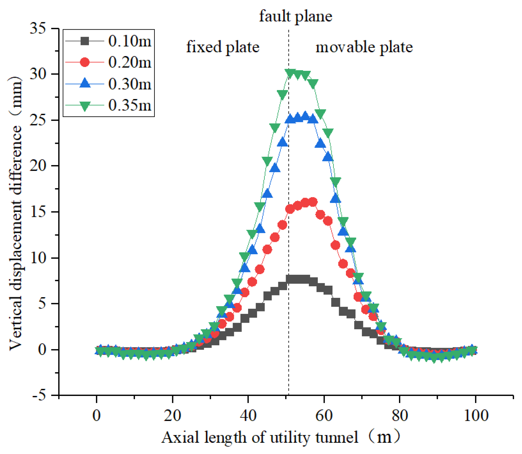
3.1. Influence of Fault Displacement

This section analyzes the response characteristics of a prefabricated utility tunnel when the fault displacements are 0.10, 0.20, 0.30, and 0.35 m under the action of a reverse fault.

3.1.1. Analysis of Vertical Displacement

Figure 6 shows the distribution curve of the vertical displacement of the utility tunnel along the axial-length direction under different fault displacements. Figure 7 shows the distribution curve of the vertical displacement difference at both ends of a single-section utility tunnel along the axial-length direction under different fault displacements. According to Figure 6 and Figure 7, the vertical displacement and the vertical displacement difference increase with increasing fault displacement, and the differential settlement of the utility tunnel is more significant when the distance to the fault plane is shorter. Under a fault displacement of 0.35 m, the vertical displacement of the utility tunnel at the fault plane is 0.137 m, which indicates that the bending deformation of the utility tunnel in the movable plate is more significant, while there is a slight difference between the bending deformation of the utility tunnel on both sides of the fault plane under the action of a normal fault [6].

3.1.2. Analysis of the Longitudinal Horizontal Opening Displacement

Figure 8a,b show the displacement distribution curves of the longitudinal horizontal openings displacement of the roof and floor of the spliced joints of the utility tunnel along the axial-length under different fault displacements. According to this figure, there is basically a positive correlation between the opening displacement and the fault displacement. A negative value indicates that the opening displacement increases and the waterproofing capacity decreases. Because of these observations, this section and the sections that follow only analyze the negative part of the opening displacement. At a position 6 m from the fault plane in the fixed plate, the opening displacement of the floor reaches the maximum values: 0.300, 0.631, 2.006, and 3.017 mm; at a position 14 m from the fault plane in the movable plate, the opening displacement of the roof reaches the maximum values: 1.343, 2.877, 4.465, and 5.133 mm.
Figure 9 shows the relationship between the maximum opening displacement and fault displacement under the action of a normal fault [6] and a reverse fault. According to this figure, within the fault displacement range 0.10–0.35 m, the maximum opening displacement of roof under the action of a reverse fault is greater than under the action of a normal fault; for the floor, the maximum opening displacement under the action of a reverse fault is smaller than under the action of a normal fault, except for a fault displacement of 0.10 m.

3.2. Influence of Burial Depth

The open-cut method is generally used for the construction and installation of urban utility tunnels, so the buried depth is usually shallow [3]. This section discusses the response of a utility tunnel under burial depth of 2, 3, 4, and 5 m.

3.2.1. Analysis of the Vertical Displacement

Figure 10 shows the distribution curve of the vertical displacement along the axial-length direction of the utility tunnel under different burial depths. Figure 11 shows the distribution curve of the vertical displacement differences at both ends of a single-section utility tunnel along the axial-length direction under different burial depths. According to Figure 10, small-scale changes in burial depths have minor effects on the vertical displacement of the utility tunnel under the action of reverse faults. According to Figure 11, the vertical displacement difference increases with increasing burial depth at a position close to the fault plane. This difference is not significant, however, and the maximum difference under different burial depths is 1.39 mm. In general, small-scale changes in the burial depths may have minor effects on the overall deformation of the utility tunnel structure under the action of reverse faults.

3.2.2. Analysis of Longitudinal Horizontal Opening Displacement

Figure 12a,b show the distribution curves of the longitudinal horizontal openings displacement of the roof and floors of the spliced joints of the utility tunnels along the axial-length direction under different burial depths. According to Figure 12a, the opening displacement of the roof near the fault plane roughly increases with increasing burial depth. The maximum opening displacements under burial depths of 2, 3, 4, and 5 m are 4.261, 4.465, 4.538, and 4.632 mm, respectively. According to Figure 12b, the opening displacement of the floor near the fault plane has no regularity. The maximum openings under burial depths of 2, 3, 4, and 5 m are 2.153, 2.006, 2.004, and 1.975 mm, respectively. The reason of this phenomenon may be when the burial depth increases, the load on the top of the utility tunnel increases, and at the same time, the constraining force of the soil on the utility tunnel also increases.

3.3. Influence of Utility Tunnel-Soil Friction Coefficient

The changes in the soil type or the differences in the surface-treatment measures for the utility tunnel lead to variations in coefficients of friction between the utility tunnel and the soil. This section discusses the response of a utility tunnel when the utility tunnel-soil friction coefficients are 0.3, 0.5, 0.7, and 0.9.

3.3.1. Analysis of Vertical Displacement

Figure 13 shows the distribution curve of the vertical displacement of a utility tunnel along the axial-length direction under different utility tunnel-soil friction coefficients. Figure 14 shows the distribution curve of the vertical displacement differences at both ends of a single-section utility tunnel along the axial length under different utility tunnel-soil friction coefficients. According to Figure 13 and Figure 14, there is almost no difference in the vertical displacement and the vertical displacement difference under different utility tunnel-soil friction coefficients. The maximum difference in the vertical displacement difference under different utility tunnel-soil friction coefficients is 0.16 mm. In general, the change in utility tunnel-soil friction coefficient may have little effect on the overall deformation of the utility tunnel structure, and a similar phenomenon was also found in a pipeline [27,28].

3.3.2. Analysis of Longitudinal Horizontal Opening Displacement

Figure 15a,b show the distribution curves of the longitudinal horizontal opening displacement of the roof and floor of the spliced joints of a utility tunnel along the axial-length direction under different utility tunnel-soil friction coefficients. According to Figure 15a, varying the utility tunnel-soil friction coefficient has little effect on the opening displacement of the roof, and the maximum difference in the opening displacement under different utility tunnel-soil friction coefficients is 0.083 mm; According to Figure 15b, in the proximity of a fault plane, although the opening displacement of floor generally decreases with increasing utility tunnel-soil friction coefficient, this effect is insignificant. The maximum difference in the opening displacement under different utility tunnel-soil friction coefficients is 0.249 mm.

3.4. Influence of Crossing Angle of Utility Tunnel

The crossing angles between the underground structures and the fault planes vary in practical engineering, and the structural responses under different crossing angles have differences [21]. This section analyzes the deformation of a prefabricated utility tunnel when the crossing angles are 45°, 60°, 75°, and 90°. Under this, then, the limiting condition is that the fault plane and the mid-span of the pipe gallery intersect at the same position when the model is being established. The model size, when the utility tunnel and a fault plane are obliquely intersected at 60°, is shown in Figure 16.

3.4.1. Analysis of Vertical Displacement

Figure 17 shows the distribution curve of the vertical displacement of the utility tunnel along the axial-length direction under different crossing angles. Figure 18 shows the distribution curve of the vertical displacement difference at both ends of a single-section utility tunnel along the axial-length direction under different crossing angles. According to Figure 17 and Figure 18, with an increase in the crossing angle, the influence range of the fault displacement on the bending deformation of the utility tunnel gradually decreases, and the vertical displacement difference near the fault plane gradually increases, and the vertical displacement difference away from the fault plane gradually decreases. The reason for this phenomenon may be that the torsion effect of the utility tunnel decreases with the increase in crossing angle.

3.4.2. Analysis of Longitudinal Horizontal Opening Displacement

Figure 19a,b show the distribution curves of the longitudinal horizontal opening displacement of the roof and floor of the spliced joints of a utility tunnel along the axial-length under different crossing angles. The opening displacement of the roof and the floor is positively correlated with the crossing angle at the position close to the fault plane, and is negatively correlated with the crossing angle at the position away from the fault plane to a certain extent. For the floor, the opening displacement under the orthogonal condition (90°) does not meet the above regularity in some positions. The maximum difference in the roof opening displacement under different crossing angles is 1.80 mm, and the maximum difference in the floor opening displacement is 0.99 mm. When the crossing angle increases from 45° to 90°, the maximum opening displacement of the roof reaches 2.833, 3.628, 4.087, 4.465 mm, and the floor reaches 1.303, 1.833, 2.135, and 2.006 mm. At the same axial position, it can be considered that the closer the crossing angle is to 90°, the difference in the opening displacement of the roof and the floor under different crossing angles is smaller.

4. Conclusions

Using the ABAQUS finite element software, this study primarily analyzed the effects of four factors, namely, fault displacement, burial depth, utility tunnel-soil friction coefficient, and the angle of a utility tunnel crossing a fault plane, on the overall deformation of prefabricated utility tunnel structures, and the deformation of their spliced joints under the action of reverse faults. The main conclusions include:
(1)
When the fault displacement increases from 0.10 to 0.35 m, the maximum opening displacement of the floor increases from 0.300 to 3.017 mm, and the roof increases from 1.343 to 5.133 mm. The overall deformation of a utility tunnel, and the deformation of the spliced joints increase with increasing fault displacement, which significantly reduces the waterproofing ability of the spliced joints.
(2)
Variations in the burial depths and utility tunnel-soil friction coefficients have little effect on the deformation of the prefabricated utility tunnel.
(3)
When the crossing angle increases from 45° to 90°, the maximum opening displacement of the floor increases from 1.303 to 2.135 mm, and the roof increases from 2.833 to 4.465 mm. To a certain extent, in the proximity of a fault plane, the overall deformation of the prefabricated utility tunnel and the deformation of the spliced joints increase with an increase in the crossing angles, as opposed to the position away from a fault plane.
The deformation of the spliced joints of a prefabricated utility tunnel is a serious problem under the action of fault displacement. In order to alleviate the waterproofing decline caused by the fault displacement, a rubber strip with good elastic recovery ability should be selected. In order to use the results of this research in practical designs, more investigations and physical modeling are needed.

Author Contributions

Conceptualization, X.W. and Y.T.; methodology, X.W.; software, C.N.; validation, D.L. and F.Q.; formal analysis, C.N.; data curation, C.N.; writing—original draft preparation, X.W.; writing—review and editing, Y.T.; visualization, D.L. and F.Q.; supervision, X.W. and Y.T. All authors have read and agreed to the published version of the manuscript.

Funding

This work was supported by the National Natural Science Foundation of China (51878222), Xiamen Construction Science and Technology plan project (XJK2020-1-9), Science and Technology Planning Project of Guangzhou (202102080269), and the Systematic Project of Guangxi Key Laboratory of Disaster Prevention and Engineering Safety (2021ZDK007).

Institutional Review Board Statement

Not applicable.

Informed Consent Statement

Not applicable.

Data Availability Statement

Not applicable.

Conflicts of Interest

The authors declare no conflict of interest.

References

  1. Luo, Y.; Alaghbandrad, A.; Genger, T.K.; Hammad, A. History and recent development of multi-purpose utility tunnels. Tunn. Undergr. Space Technol. 2020, 103, 103511. [Google Scholar] [CrossRef]
  2. Ghavami, S.; Saeedi Azizkandi, A.; Baziar, M.H.; Rajabi, M. Interaction of Underground Tunnel and Existing Shallow Foundations Affected by Normal Faults. J. Seismol. Earthq. Eng. 2019, 21, 57–62. [Google Scholar]
  3. Lin, Z.Z.; Guo, C.C.; Ni, P.P.; Cao, D.F.; Huang, L.; Guo, Z.F.; Dong, P. Experimental and numerical investigations into leakage behaviour of a novel prefabricated utility tunnel. Tunn. Undergr. Space Technol. 2020, 104, 103529. [Google Scholar] [CrossRef]
  4. Wu, X.G.; Chen, X.K.; Yu, S.Y.; Hong, S.; Kang, T.H.K. Experimental Study on Waterproofing Properties of Putty-Based Composite Rubber Strip for Underground Post-Tensioned Precast Concrete Structures. Int. J. Concr. Struct. Mater. 2019, 13, 8. [Google Scholar] [CrossRef]
  5. Iakovleva, E.; Belova, M.; Soares, A. Allocation of potentially environmentally hazardous sections on pipelines. Geosciences 2021, 11, 3. [Google Scholar] [CrossRef]
  6. Wu, X.G.; Nie, C.H.; Qiu, F.Q.; Zhang, X.S.; Li, H.; Lee, J.S.; Kang, T.H.K. Analysis of underground post-tensioned precast concrete box utility tunnel under normal fault displacement. Comput. Concr. 2022, 29, 69–79. [Google Scholar]
  7. Baziar, M.H.; Nabizadeh, A.; Lee, C.J.; Huang, W.Y. Centrifuge modeling of interaction between reverse faulting and tunnel. Soil Dyn. Earthq. Eng. 2014, 65, 151–164. [Google Scholar] [CrossRef]
  8. Kiani, M.; Akhlaghi, T.; Ghalandarzadeh, A. Experimental modeling of segmental shallow tunnels in alluvial affected by normal faults. Tunn. Undergr. Space Technol. 2016, 51, 108–119. [Google Scholar] [CrossRef]
  9. Sabagh, M.; Ghalandarzadeh, A. Numerical modelings of continuous shallow tunnels subject to reverse faulting and its verification through a centrifuge. Comput. Geotech. 2020, 128, 103813. [Google Scholar] [CrossRef]
  10. Sabagh, M.; Ghalandarzadeh, A. Centrifugal modeling of continuous shallow tunnels at active normal faults intersection. Transp. Geotech. 2020, 22, 100325. [Google Scholar] [CrossRef]
  11. Yao, C.F.; He, C.; Takemura, J.; Feng, K.; Guo, D.P.; Huang, X. Active length of a continuous pipe or tunnel subjected to reverse faulting. Soil Dyn. Earthq. Eng. 2021, 148, 106825. [Google Scholar] [CrossRef]
  12. Yan, C.F.; Takemura, J.; Ma, G.Y.; Dai, C.; An, Z.L. Effect of boundary friction on revere fault rupture propagation in centrifuge tests. Soil Dyn. Earthq. Eng. 2021, 147, 106811. [Google Scholar]
  13. Zhou, G.; Sheng, Q.; Cui, Z.; Wang, T.; Ma, Y. Investigating the Deformation and Failure Mechanism of a Submarine Tunnel with Flexible Joints Subjected to Strike-Slip Faults. J. Mar. Sci. Eng. 2021, 9, 1412. [Google Scholar] [CrossRef]
  14. Demirci, H.E.; Karaman, M.; Bhattacharya, S. Behaviour of buried continuous pipelines crossing strike-slip faults: Experimental and numerical study. J. Nat. Gas Sci. Eng. 2021, 92, 103980. [Google Scholar] [CrossRef]
  15. Wei, X.L.; Jiao, W.S.; Zeng, X.; Zhang, D.F.; Du, G.F. Mechanical Behavior of Buried Pipelines Subjected to Faults. Adv. Civ. Eng. 2021, 3, 9984519. [Google Scholar] [CrossRef]
  16. Roudsari, M.T.; Hosseini, M.; Ashrafy, M.; Azin, M.; Nasimi, M.; Torkaman, M.; Khorsandi, A. New Method to Evaluate the Buried Pipeline-Sandy Soil Interaction Subjected to Strike Slip Faulting. J. Earthq. Eng. 2022, 26, 89–112. [Google Scholar] [CrossRef]
  17. Baziar, M.H.; Nabizadeh, A.; Mehrabi, R.; Lee, C.J.; Hung, W.Y. Evaluation of underground tunnel response to reverse fault rupture using numerical approach. Soil Dyn. Earthq. Eng. 2016, 83, 1–17. [Google Scholar] [CrossRef]
  18. Azizkandi, A.S.; Ghavami, S.; Baziar, M.H.; Hasanaklou, S.H. Assessment of damages in fault rupture-shallow foundation interaction due to the existence of underground structures. Tunn. Undergr. Space Technol. 2019, 89, 222–237. [Google Scholar] [CrossRef]
  19. Triantafyllaki, A.; Papanastasiou, P.; Loukidis, D. Numerical analysis of the structural response of unburied offshore pipelines crossing active normal and reverse faults. Soil Dyn. Earthq. Eng. 2020, 137, 106296. [Google Scholar] [CrossRef]
  20. Dey, S.; Chakraborty, S.; Tesfamariam, S. Structural performance of buried pipeline undergoing strike-slip fault rupture in 3D using a non-linear sand model. Soil Dyn. Earthq. Eng. 2020, 135, 106180. [Google Scholar] [CrossRef]
  21. Li, F.T.; Wang, Q.Y.; Hu, Z.P.; Zhang, Y.H.; Ren, X.; An, X.X. The Effect of Intersection Angle on the Failure Mechanism of Utility Tunnel. Adv. Civ. Eng. 2020, 2020, 8864676. [Google Scholar]
  22. Zhang, D.; Hu, Z.P.; Lu, G.G.; Wang, R.; Ren, X. Experimental Study on Deformation Mechanism of a Utility Tunnel in a Ground Fissure Area. Adv. Mater. Sci. Eng. 2020, 2020, 6758978. [Google Scholar] [CrossRef]
  23. Yan, Y.F.; Qiu, J.L.; Huang, Q.B.; Wang, Z.C.; Xie, Y.L.; Liu, T. Ground fissures geology in Xi’an and failure mitigation measures for utility tunnel system due to geohazard. Arab. J. Geosci. 2021, 14, 1207. [Google Scholar] [CrossRef]
  24. Yan, Y.F.; Huang, Q.B.; Xie, Y.L.; Liu, T.; Xu, Q.; Fan, F.F.; Wang, Y.L. Failure analysis of urban open-cut utility tunnel under ground fissures environment in Xi’an, China. Eng. Fail. Anal. 2021, 127, 105529. [Google Scholar] [CrossRef]
  25. Deng, B.T.; Li, X.; Li, P.; Tian, J.T.; Li, J.H. Rationality determination method and mechanical behavior of underground utility tunnels in a ground fissure environment. Bull. Eng. Geol. Environ. 2022, 81, 50. [Google Scholar] [CrossRef]
  26. Tang, L.J.; Wang, Z.G.; An, S.; Shi, C.; Shi, M.; Dong, R.L.; Cao, Q.K. Experimental study on the mechanical behavior of utility tunnel with flexible joints passing through active thrust fault. Arab. J. Geosci. 2021, 14, 2579. [Google Scholar]
  27. Zhang, J.; Liang, Z.; Han, C.J. Numerical modeling of mechanical behavior for buried steel pipelines crossing subsidence strata. PLoS ONE 2015, 6, 1–16. [Google Scholar] [CrossRef] [Green Version]
  28. Zhang, J.; Xie, R. Numerical analysis of mechanical behavior of buried pipes in subsidence area caused by underground mining. J. Press. Vessel. Technol. 2019, 141, 021703. [Google Scholar] [CrossRef]
Figure 1. Three-dimensional schematic diagram of the single-section utility tunnel.
Buildings 12 01086 g001
Figure 2. Overall schematic diagram of the numerical mode.
Buildings 12 01086 g002
Figure 3. Boundary condition setting.
Buildings 12 01086 g003
Figure 4. Meshing of the utility tunnel.
Buildings 12 01086 g004
Figure 5. Meshing of the soil.
Buildings 12 01086 g005
Figure 6. Vertical displacement distribution curve.
Buildings 12 01086 g006
Figure 7. Vertical displacement difference distribution curve.
Buildings 12 01086 g007
Figure 8. Distribution curves of the longitudinal horizontal opening displacement. (a) Roof (b) Floor.
Buildings 12 01086 g008
Figure 9. Relationship between the maximum opening displacement and fault displacement.
Buildings 12 01086 g009
Figure 10. Vertical displacement distribution curve.
Buildings 12 01086 g010
Figure 11. Vertical displacement difference distribution curve.
Buildings 12 01086 g011
Figure 12. Distribution curves of the longitudinal horizontal opening displacement. (a) Roof (b) Floor.
Buildings 12 01086 g012
Figure 13. Vertical displacement distribution curve.
Buildings 12 01086 g013
Figure 14. Vertical displacement difference distribution curve.
Buildings 12 01086 g014
Figure 15. Distribution curve of the longitudinal horizontal opening displacement. (a) Roof (b) Floor.
Buildings 12 01086 g015
Figure 16. Schematic diagram of the size of the soil model of the integrated pipe gallery under 60° crossing angle (unit: m).
Buildings 12 01086 g016
Figure 17. Vertical displacement distribution curve.
Buildings 12 01086 g017
Figure 18. Vertical displacement difference distribution curve.
Buildings 12 01086 g018
Figure 19. Distribution curve of the longitudinal horizontal opening displacement. (a) Roof (b) Floor.
Buildings 12 01086 g019
Table 1. Material parameters of the soil.
Density
(kg/m3)
Elastic Modulus (MPa)Poisson’s RatioInternal Friction Angle (°)Cohesion (kPa)
190080.32020
Table 2. Material parameters of the utility tunnel and cushion.
NameCategoryDensity
(kg/m3)
Elastic Modulus (MPa)Poisson’s Ratio
Utility TunnelC50 concrete250034,5000.2
CushionC20 concrete240025,5000.2
Table 3. Working conditions of the influencing factors analysis.
Working ConditionDip Angle (°)Fault Displacement (m)Burial
Depth (m)
Utility Tunnel-Soil Friction CoefficientCrossing Angle (°)
1900.1/0.2/0.3/0.3530.790
2900.32/3/4/50.790
3900.330.3/0.5/0.7/0.990
4900.330.745/60/75/90
Publisher’s Note: MDPI stays neutral with regard to jurisdictional claims in published maps and institutional affiliations.

