1. Introduction
A construction site is a hazardous setting that poses numerous risks to workers [
1,
2], such as through the use of heavy machinery, dangerous tools, and large materials. In addition, the interactions of different work teams on a construction site generate a complex and broad diversity of potential scenarios that are challenging to coordinate in a safe manner because each group has its own specific, and often conflicting, objectives [
3]. Each professional has very different tasks and goals to achieve, but all of them are sharing the same space, so they are affecting the work of others, crossing safety zones, or breaking into the wrong spaces [
4]. Taken together, these elements make the Architecture, Engineering, Construction, and Operation (AECO) industry one of the most dangerous industries in the world, as indicated by it having one of the highest global accident rates.
Health and safety is therefore a relevant discipline for the construction sector. This discipline is responsible for the design and implementation of occupational risk mitigation and prevention plans to avoid accidents in the workplace and protect the welfare of workers. Different measures can be applied. Proactive construction safety management measures are deployed at different temporal stages and organisational levels. They consider a broad time frame of action, from design to influencing the best decisions, avoiding transfer to contractors during construction, identifying site risks, and generating design solutions that reduce or avoid hazardous work environments. In addition, the identification and communication of unavoidable risk areas enables the planning and development of accident mitigation plans and prevention measures. In this sense, achieving a real awareness of workers is relevant to forming a culture of safety. With this, safety plans must be implemented at the construction site. These safety measures are reflected in the fact that workers use personal protective equipment (PPE) and engage in safe behaviours (as a result of training and safety culture). In addition, collective protection elements (CPE) are correctly placed throughout the construction site. Health and safety on-site is a field in which there is ample room for improvement, and thus there is a central focus on accelerating the improvement of measures and practices in construction enterprises in order to protect workers from potential injuries [
5].
CPE are all those protection elements that are situated in risk areas and which protect groups of workers. CPE are considered ‘of passive operation’ because they do not require the user’s action (unlike individual protective equipment, where the worker is responsible for putting on the necessary equipment). Thus, the layout of CPE in the worksite involves certain challenges, which are primarily associated with the changing worksite environment. During construction, the configuration of the worksite changes every day; therefore, the collective protection measures must adapt to these new configurations and the different tasks to be performed. To meet such challenges, safety managers design the protective measures associated with each task and place the protective measures at different locations on the site. On top of this, it is also typical to identify unprotected areas, either because they have been wrongly removed (through ignorance or carelessness) or because they have not been put in place in time. Therefore, regular inspection of the presence of CPE is crucial. Identifying and correcting these faults in time ensures the protection of workers and provides rapid continuity of work. These inspections are traditionally carried out using checklists, paper checklists, or applications (apps), whereby inspectors walk around the worksite and visually check whether the protective measures are in place. While it is possible to record items and verify their presence/absence, the effectiveness of the inspection is limited to the experience of the professional in charge and their ability to recognise CPE in the workplace.
Emerging technologies, particularly digitalisation, represent an opportunity to invest resources and efforts to improve health and safety in construction [
6]. The industry is searching for new radical solutions based on other ongoing paradigm shifts to enhance performance regarding Occupational Risk Prevention (ORP). On the one hand, building information modelling (BIM) seeks to integrate people, processes, and technologies, incorporating safety aspects in the models of projects [
7]. On the other hand, lean construction (LC), the continuous improvement of safety management processes, is based on lean management’s lossless production principles. In addition, Design through Prevention (DtP) incorporates safety considerations from the early stages of the project and promotes monitoring and control throughout the project [
8]. Digital technologies and computation form the basis of increasing efficiency in information exchange processes and their development in a complex growing environment, such as current construction sites [
9,
10].
In order to develop on-site digital model visualisations, augmented reality (AR) technologies were analysed [
11], who identified a trend of applying sophisticated immersive AR solutions to create interfaces to manage complex workplace situations, building up risk-preventive knowledge and supporting training. Research projects such as this show that AR enhances a person’s perception by superimposing virtual models onto the real environment [
12,
13]. Augmented reality linked to BIM models is being tested in the construction sector for different purposes. Through the use of AR, it is possible to compare BIM models with real elements on the worksite, superimposing virtual elements onto real ones, verifying dimensions, and validating technical characteristics. In addition, AR facilitates the use of tracking machinery and cranes on the job site, confirming the distribution of materials and interaction zones as well as allowing virtual signage to be placed on the worksite to improve movement around the site and display information on elements of interest. This extra information accessible in real time is an asset that can aid in tasks such as the inspection of the safety equipment present on-site.
Although AR has enormous potential for construction sites, its use is not massive [
14]. The industry has not yet massively adopted its use because it is considered an expensive and immature technology. However, despite this (understanding the rapid development of technologies, reducing costs), the development of capabilities in the sector’s professionals, the establishment of protocols, and standardised developments of these applications are more relevant challenges. Along with this, those who promote AR and other technologies of this type must be explicit and demonstrate the benefits of their use for different specific tasks in construction [
15,
16]. The applications of AR in construction need to be diversified and integrated with BIM. Although several authors mention the potential of this technology for health and safety in construction, there is little evidence of applications for safety (no specific applications have been identified for CPE management). Despite this, no protocols standardise the development and use of augmented reality in safety management (project review, on-site inspection, monitoring and control of protective elements, management of preventive measures). Workflows are needed to guide professionals in the development of applications in order to better integrate AR into their processes. In addition, standardisation is necessary to move towards the automation of the development of these applications [
17,
18,
19].
Given the relevance of the inspection processes of safety elements at the construction site, this work analyses the traditional inspection processes of CPE at the worksite and studies the potential of AR to evaluate the presence of these elements, providing recommendations for the development of AR applications for these purposes, together with indicators to assess their performance. Thus, this work does the following:
Studies and analyses the traditional flow of safety inspections at construction sites, identifying their methods, main pain points, and bottlenecks, along with the key performance indicators for these inspections.
Designs a conceptual proposal for an AR application for CPE identification. Different layers of information are proposed, along with detailed functional requirements of the app, proposed user interfaces, and a workflow to perform the inspections. In addition, key performance indicators have been created to evaluate these applications.
Develops an application in AR, showing the necessary steps so that other people can develop similar applications, together with an evaluation of the application based on different criteria and proposed KPIs.
The relevance of this work lies in providing background for the use of AR in safety inspection processes on construction sites and in providing methodological recommendations for the development and evaluation of these applications.
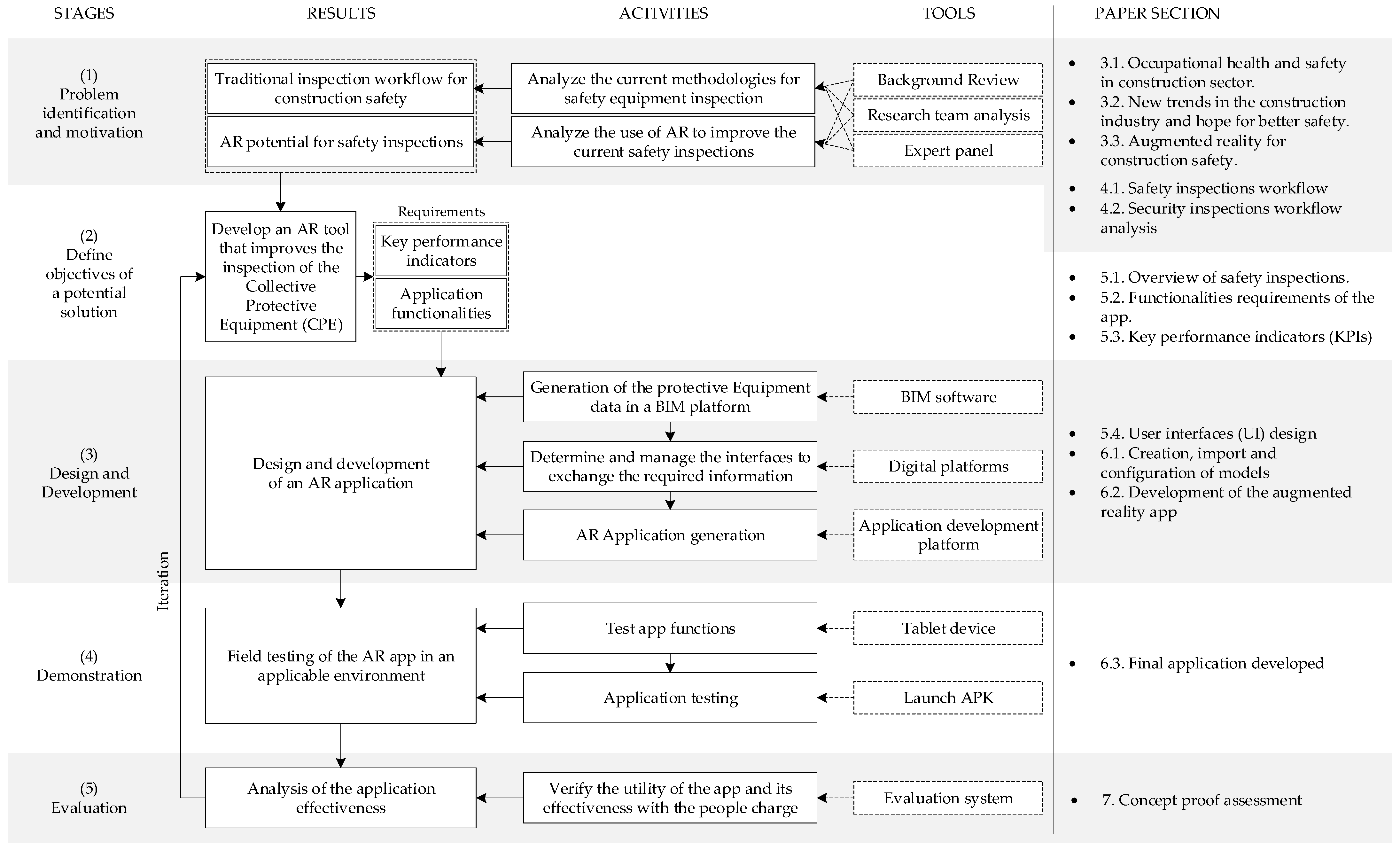
2. Research Methodology
For the development of this research, the design science research methodology (DSRM) is used as a base to describe the process of justification, development, and testing [
20,
21]. The phases of this methodology are presented in
Figure 1.
A background review is carried out in the first stage, based on SCOPUS and the Web of Science libraries. Background information is collected in order to study the methods of inspection of safety elements at the construction site, to understand the relevance of their proper placement, and to determine how the use of augmented reality (AR) technology can help the safety advisor to identify and manage this equipment in such a way as to increase the reliability of the presence and effectiveness of the collective protective equipment (CPE). Based on this background, the research team outlines a traditional inspection workflow for building construction safety elements.
Next, the following actions are carried out to analyse the proposed flow:
The proposed workflow is analysed and validated by a panel of industry professionals and researchers with expertise in building safety management and/or new technologies for building safety. Six experts were selected who met the following requirements: (a) more than eight years of practice and (b) experience as a consultant or researcher in building safety management and new technologies for building safety. Three expert professionals from Belgium and three from Spain were selected (the countries in which this study’s authors are located).
Table 1 shows the characteristics of the expert panel.
A construction site is visited to compare the proposed traditional inspection flow with the inspection flow developed on a real worksite.
Key performance indicators are defined, and an overall assessment of the traditional security inspection method is carried out.
Finally, the main problems and bottlenecks in the traditional workflow are identified.
In the second stage, the objective of developing an AR-based solution is defined: building an AR tool to improve the inspection of the equipment involved in a construction site, increasing the reliability of the presence and effectiveness of the CPE. To this end, the application functionalities and key performance indicators were defined.
In the third stage, the AR application is designed, implemented, and deployed according to the following steps: (a) development of the 3D model of the work site and the CPE data in a BIM platform; (b) definition of user interfaces and their information management processes for the AR application; and (c) AR application development. In the fourth stage, to test the AR application’s functionalities, a proof of concept in a real environment is performed. Finally, in stage five, an analysis of the application’s effectiveness is carried out based on defined quantitative and qualitative KPIs, according to the solution’s requirements.
3. Background
3.1. Occupational Health and Safety in the Construction Sector
The most significant peculiarity of the construction industry concerning many others, particularly those under the name industry 4.0, such as the automotive industry or the aeronautical industry, is the workplace during the execution phase. This pertains to the tasks performed by workers to change a site (the ground, the structure, the environment) and to build a new space (a place to live, move, or work, ultimately) [
22]. Therefore, the construction site is in a constant state of change due to the continuous tasks performed by the numerous stakeholders involved [
6]. The final product is always different because it is linked to the setting involved. Its development is thus subject to several uncertainties, which can cause sequential delays in the project. Since a construction site is a complex place to work due to the many factors involved, ensuring safety is also a very difficult task as it is not easy to standardise; nevertheless, the trend seen in the majority of companies is to develop a series of measures and improvements to protect their workers [
6,
23].
Continuous improvement processes to enhance safety are needed while accidents and fatalities continue to occur [
24]. It is well known that the construction industry is one of the most hazardous industries in which to work; however, the vast majority of the risks on-site can be avoided by implementing the proper health and safety prevention techniques [
25]. Many studies have produced evidence that there is much room for improvement in this regard. According to the current data on the accidents in the industry [
26], the main causes of accidents are as follows:
- (a)
lack of fall protection (CPE and individual protective equipment (IPE)) for workers on elevated structures;
- (b)
lack of protection against falling objects for people on the ground;
- (c)
unsafe equipment;
- (d)
unsafe property conditions;
- (e)
tripping hazards caused by construction materials and debris;
- (f)
missing guards or protections on power tools;
- (g)
lack of safety precautions when working near power lines.
The regulation in terms of health and safety in construction is broadly similar across most of the countries in the European Union. Safety advisors are responsible for the coordination of the tasks that are performed on-site, and they make sure all work complies with the proper safety measures.
3.2. New Trends in the Construction Industry and Hope for Better Safety
During recent years, the construction industry has undergone several changes, primarily as a consequence of the inevitable rise of technology, which has led to the modernisation of the industry. There are five major changes foreseen in the concept of construction 4.0, which is defined as the finding of coherent complementarity between the main emerging technological approaches in the industry to improve real-time decision making [
11], which are the following:
Construction software and full integration. This primarily focuses on improving the communication between the different stakeholders involved in order to create a more advanced integrating methodology [
27,
28].
Augmented and virtual reality. These can enhance the overview of the project by superimposing a virtual model of the infrastructure, which prevents costly construction mistakes [
29,
30]. They can also aid with visualisation in poor-visibility environments (e.g., in mines or underwater) and in the use of cranes, among other machinery [
12,
31].
Next generation of tools. The upcoming devices are more sophisticated and interconnected, enabling them to send and receive data (internet of things). Machine learning (ML) and artificial intelligence (AI) can also promote the upskilling of industry workers in areas such as risk management, schedule management, subcontractor management, construction site monitoring, and ORP, among others [
10].
New workforce types. The new generation of workers, who are more comfortable with technology, can strongly influence the methodological approach to the use of technology in the very near future [
32,
33]. Additionally, these changes in the industry would attract younger and better-prepared professionals looking to capitalise on the trend of digitalisation.
3.3. Augmented Reality for Construction Safety
The inclusion of the BIM methodology in the development of construction projects has meant an important advance for improving process efficiency [
34]. The visualisation of 3D models provides important support for resolving conflicts and doubts at the time of construction [
35]. The automatic connection of 3D models with budgets and schedules facilitates on-site management, among other multiple benefits. The link between BIM and visualisation technologies such as augmented reality seems natural [
36,
37].
Several authors have discussed the benefits and potential of augmented reality for the construction site. The main value is visualising information graphics and data on the real construction site [
38,
39]. In the construction stages, the visualisation of the components to be built and the construction stages for a specific construction site allows for the clarification of the construction process’s doubts to the work team, thus improving the quality of the construction and avoiding the need for rework. In addition, the data associated with the 3D models (linked to the schedule and costs, 4D and 5D models) allow clarification of technical specifications, details of specific materials and equipment, and other relevant information for the construction process [
40,
41].
Augmented reality is used to install mechanical, electrical, and plumbing systems among the main applications. Many systems in projects, mainly building projects (hospital projects, for example), generate problems during installation. Augmented reality coordinates and situates the systems in the specific locations determined in the design phase. The BIM MEP models are virtually superimposed on AR devices so that each team places the systems in the corresponding location. Thus, rework, network malfunctions, or unexpected adjustments are reduced [
38,
42,
43,
44]. In addition, augmented reality visualisation of building systems and equipment allows access to operational and maintenance information, facilitating facility management processes [
45,
46].
Several authors indicate the potential of augmented reality for health and safety management in construction. The use of AR improves workers’ ability to identify and recognize hazards [
47] due to the possibility of monitoring the project’s status and working conditions using AR devices [
48]. In addition, it allows them to interact in the real world with a virtual layer of information, which has the potential to alert them to hazards or potential accidents [
48]. Access to virtual information from the devices the worker interacts with on the job site gives them advantages when making interaction decisions (e.g., in installations with electrical hazards) [
45,
49,
50]. Thus, there are applications to manage the safety associated with handling facilities, fire protection, crane movement, and work machinery, among others [
18,
31,
51,
52]. In managing collective protective equipment (CPE) at the construction site, no specific works on augmented reality applications have been found where procedures and methods of use are indicated. However, there is a parallelism with the use of AR in the management of MEP systems. Nevertheless, the associated management of CPE is more complex. The temporality of the on-site disposition of the CPE, the continuous verification of their absence/presence, their relevance for the continuity of the construction processes, and the safety of the workers must be considered.
Although several authors discuss the potential of augmented reality in safety, and examples of safety use have been identified, there is a lack of standardisation in the use of augmented reality tools, lacking taxonomies for their standardised use in safety review, in support of prevention plans, and in the identification, monitoring, and control of preventive measures. The need to have standardised workflows to move towards the automation of the generation of these applications, which can easily integrate safety monitoring and control data based on BIM models and data, would allow for moves towards the massification of these tools [
14,
15,
16,
17].
4. Safety Inspections Analysis
4.1. Safety Inspection Workflow
Considering that each country has specific regulations regarding construction safety measures and their associated protocols, this research aims to focus on common on-site inspection processes, prioritising generic roles and activities that can be personalised according to the specific measures of each region and company [
53,
54].
The safety advisor is responsible for the integral safety management on the construction site [
55]. Their tasks as a safety advisor can be summarised as follows: to advise and assist the Quality, Health, Safety, and Environment (QHSE) Manager in formulating and implementing the QHSE policy for the different work teams; to develop a safety culture in collaboration with the QHSE manager and to enhance continuous safety awareness in the management and the on-site employees; and to centralise, structure, and organise security priorities [
56,
57]. More specifically, by following the relevant legislation, the safety advisor must (a) analyse the risks, promote improvements, outline procedures and instructions, inspect the works on-site, formulate advice on safety aspects and installations, and coordinate with subcontractors; (b) advise and support site supervisors in the development of QHSE plans and projects; (c) carry out periodic site visits and inspections; (d) organise the welcome information and training for new employees; and (e) assist the QHSE manager in the running of the consultative bodies within the organisation [
58].
The workflow of the safety advisor’s inspections of the safety equipment can be described according to three main stages [
57,
59,
60]:
Evaluation of the risks: this task is performed before the construction is executed and for each phase to analyse the safety equipment required.
Plan preventive activities: this focuses on the (mid- to long-term culture) workers’ safety education and training, and the deployment of emergency procedures.
On-site visits: these include (a) paperwork analysis (revision of the safety plans) and (b) the on-site safety inspections (which entail walking around the construction site to check the presence and condition of the safety equipment (CPE and IPE)). As a consequence, any incident is reported. Furthermore, the measures for those workers who do not oblige with the safety measures are defined and applied; (c) report regarding the visit—it contains all the procedures and incidents that should be annotated, including pictures and other data of interest.
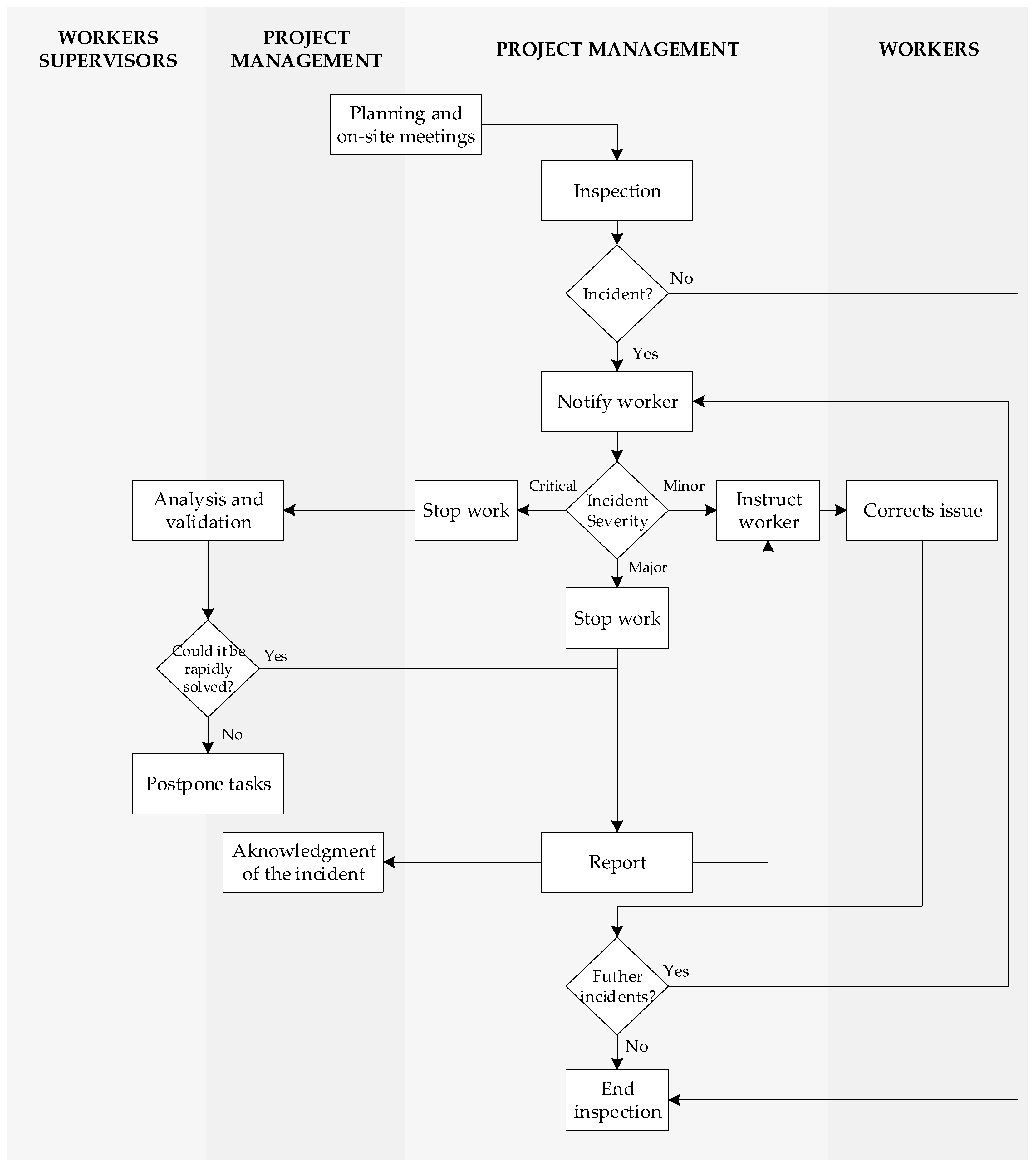
On a construction project, the safety advisor meets with the project management team to discuss and plan the work for the next days or weeks. Weekly on-site meetings with the project management team are necessary to discuss planning, progress, and delayed changes. During the on-site inspections, the SA must ensure that all the safety measures are being deployed as planned by checking whether the workers are performing their tasks in compliance with the safety measures. When these safety measures are not being followed, the job has to be stopped. In such a case, the safety advisor must apply corrective actions by modifying any protective equipment or ensuring that the workers perform their tasks appropriately. In terms of CPE, a purely visual inspection is usually sufficient. During the meetings before the inspection, the project’s phase and the safety elements must be foreseen. Using their knowledge and experience, the safety advisor must be aware of whether any CPE needs to be replaced or substituted. In the case of an incident/observation, such as a missing CPE, a worker’s misbehaviour, risks that need to be addressed, hazardous products, etc., they must issue a report [
61,
62].
Figure 2 shows the safety inspection workflow.
All incidents can be classified into three different categories, each of which requires different procedures [
63,
64,
65]:
Minor incident—in this case, the safety advisor instructs the worker to correct the issue, e.g., a worker not wearing a helmet will be instructed to wear a helmet;
Major incident—the work has to be stopped, and it is reported, e.g., a CPE is missing, or a worker is not properly tied to their life line; and
Critical incident—this is where the work is completely stopped, and a direct discussion with the project management team and the work supervisors must take place, e.g., in the case of a flood in one of the floors.
4.2. Security Inspection Workflow Analysis
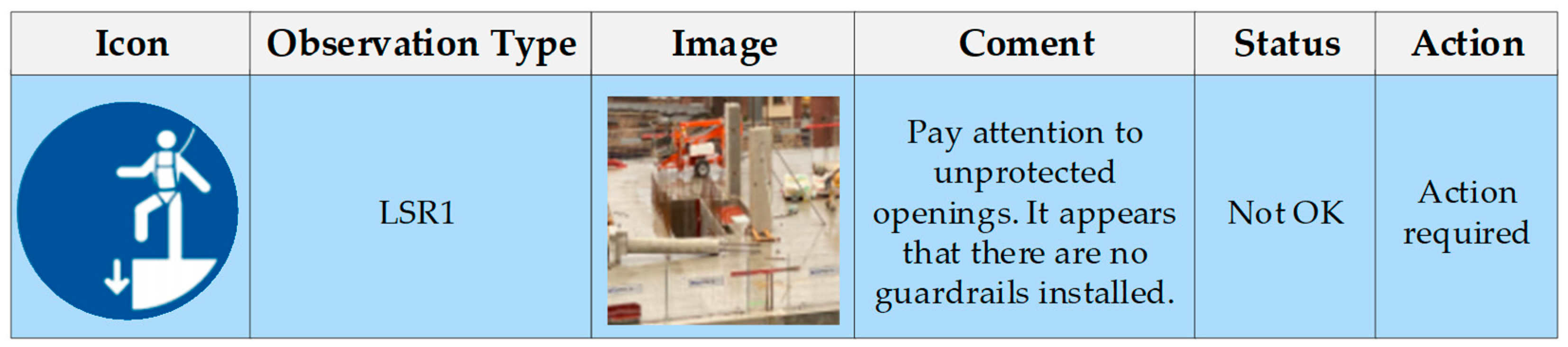
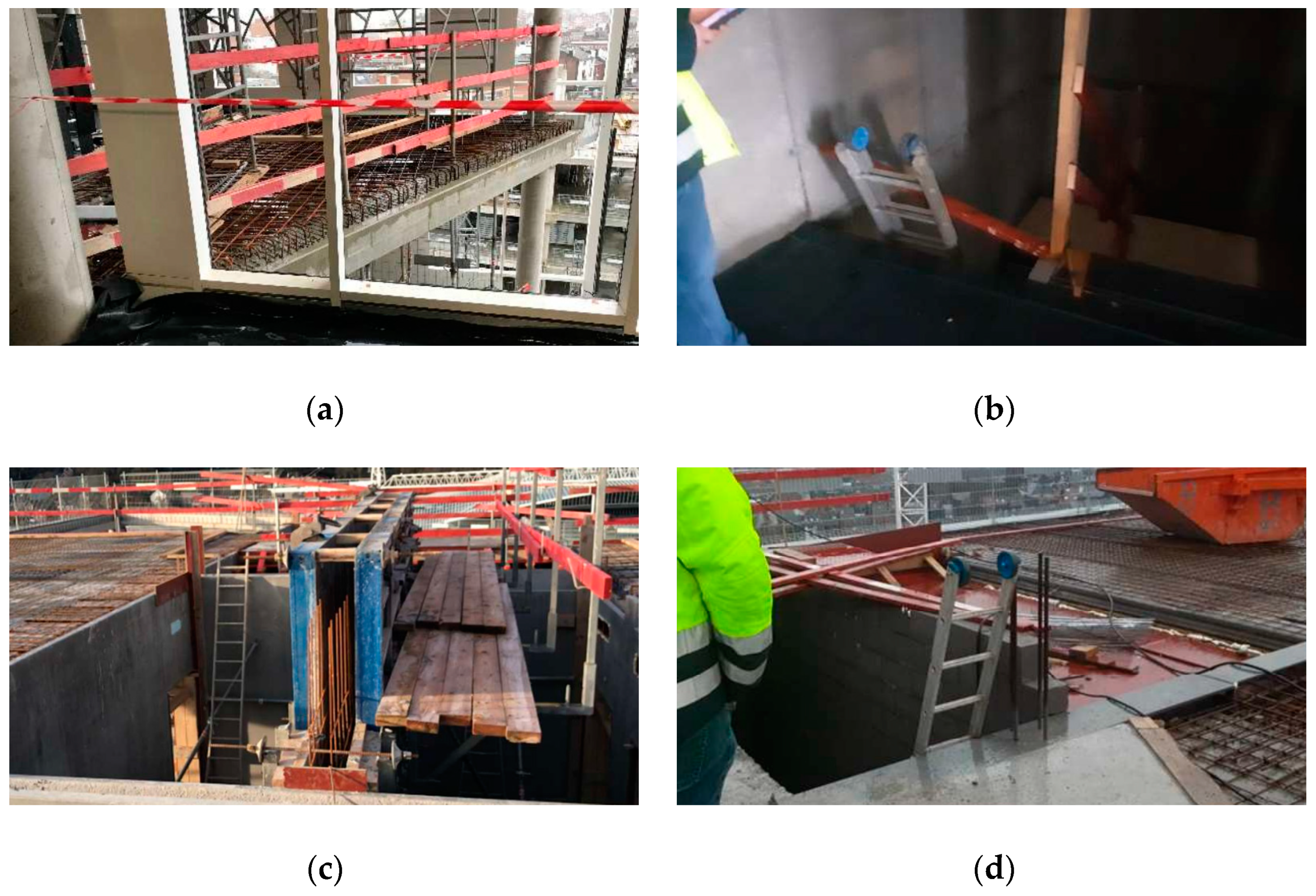
The details of a construction site were studied to validate the application of the general procedure to real situations. This site corresponds to the construction of a residential building in Belgium. Three of the members of the expert panel, two of them safety advisors, visited the site to review the on-site real-time use of the app to support the proposed inspection flow.
Figure 3 shows an example of the incident report made at the construction site, while
Figure 4 shows some of the observations made during the inspection of the project.
In order to quantify (QT) and qualify (QL) the performance of the traditional inspection, several key performance indicators (KPIs) are set.
Table 2 shows the assessment of the traditional inspection method according to what was observed in the company visited.
Once the workflow is analysed during a safety inspection, the bottlenecks (BN) and pain points (PP) should be analysed too.
Table 3 shows the main pain points and bottlenecks collected from the safety equipment inspections.
5. Conceptual Design of the Proposed Inspection
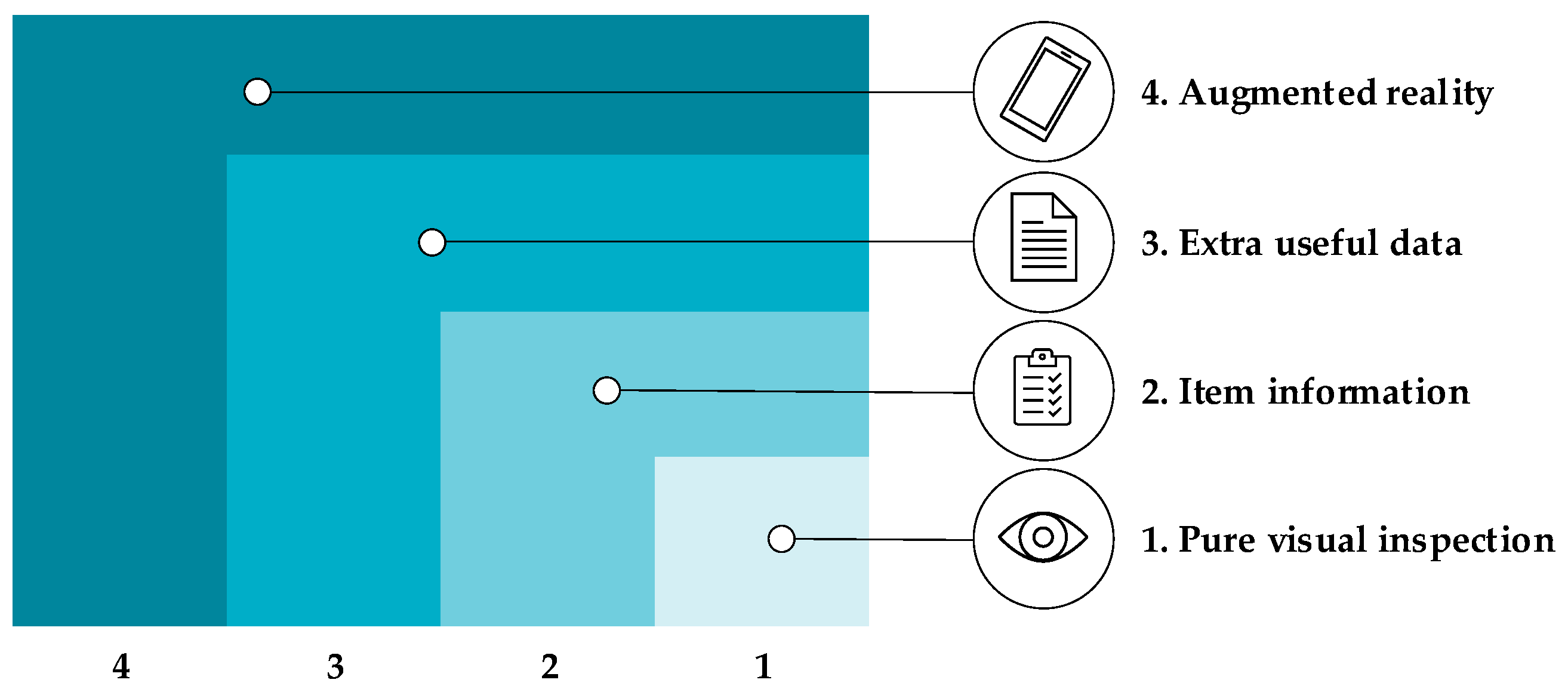
5.1. Overview of Safety Inspections
Depending on the kind of information used, different levels of data assistance can be defined for the SA. The first level is when the SA does not rely on any information, i.e., a purely visual inspection using the inspector’s knowledge, which has been the most traditional and common level over centuries of construction. The second level is when any document, either a paper or a digital version, is available to the SA that has been previously created. A third important level is when the inspection can acquire data linked to the site by using a kind of digital creation of information, including the description of the items, location, maintenance notes, etc. Lastly, the level proposed in this work consists of having an enriched layer of a combination of 3D models previously loaded with data collected on-site by using the features of the AR technology. That is why this new layer of information can be defined as an augmented vision of the setting. This analysis introduces the concept of different levels of augmented inspections.
Figure 5 schematically shows the different identified levels of augmented inspection, and
Table 4 describes each layer.
5.2. Functionality Requirements of the App
Since this research aims to study the implementation and development of the proposal, it is necessary to develop a prototype that demonstrates the capabilities of AR in the inspection workflow. The app’s functionality is designed to mitigate the main pain points identified. Some of these points and bottlenecks are related to safety management rather than the visualisation of the elements. The app interface primarily addresses the visualisation aspects and adapts the app’s data management to a workflow to facilitate communication and data processing.
Table 5 lists the difficulties in the inspection and the functions that have been developed to overcome these issues.
An important aspect of the app’s functionalities is to include the evolution of the CPE during the execution phase. The CPE models must be updated in line with the constant changes in the equipment. For example, Alcalde [
66] proposed the implementation of the equipment by using a Revit BIM model that can be easily studied in real time with Autodesk Navisworks
®. Several web pages, such as BIM Object and BIM and Co., include complete models that can be directly used without the need of modelling each construction site again. For regulatory purposes, the EPC models should be designed according to certain standards (without prejudice to the SA considering generic models for inspection only, considering that the actual ones should comply with defined specifications, the information of which could also be placed in the application).
Therefore, consideration of the time taken in the inspection of the CPE throughout the project phases is key to ensure a much more realistic supervision. An analysis carried out by Tarancon [
67] was performed to provide the timeline for each of these models, the time dimension in BIM, stating that planning of the activities undergoes continuous change and must be tracked constantly. Unexpected events always occur in construction, and managing them is key to avoid risks. To summarise, it is necessary to integrate CPE as a BIM element of the construction process to improve the planning regarding the safety equipment. This process means that the CPE 3D models can be transferred to the AR experience without having to create them. Therefore, the applicability of the concept would be eased on the assumption that the CPE must be included in the BIM libraries. The timeline of these models is an important input for safety equipment planning. This information is used in the AR experience to indicate the evolution of the models during their planning phases.
5.3. Key Performance Indicators (KPIs)
Jetter et al. [
26] indicate the most common KPIs used to evaluate AR applications. Accordingly,
Table 6 shows the KPIs considered for the evaluation of the proposed application.
5.4. User Interfaces (UI) Design
Once the aspects considered are determined, the functionalities can be created for the proposed application (see
Table 7). The details of their development are explained in the chapter on the development of the application. It is essential to categorise all these functionalities and to determine how the user interfaces (UI) are organised and presented in order to clearly understand how the app’s organisation works and how the user experiences the various functionalities inside each UI screen.
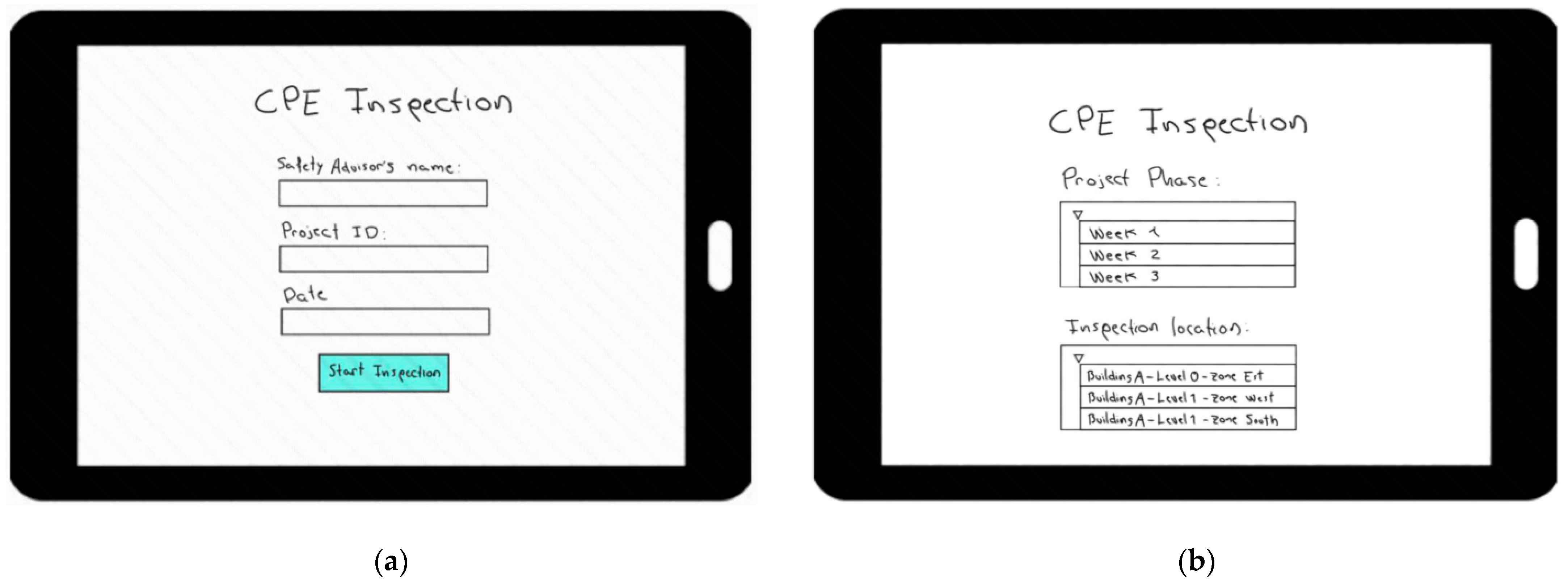
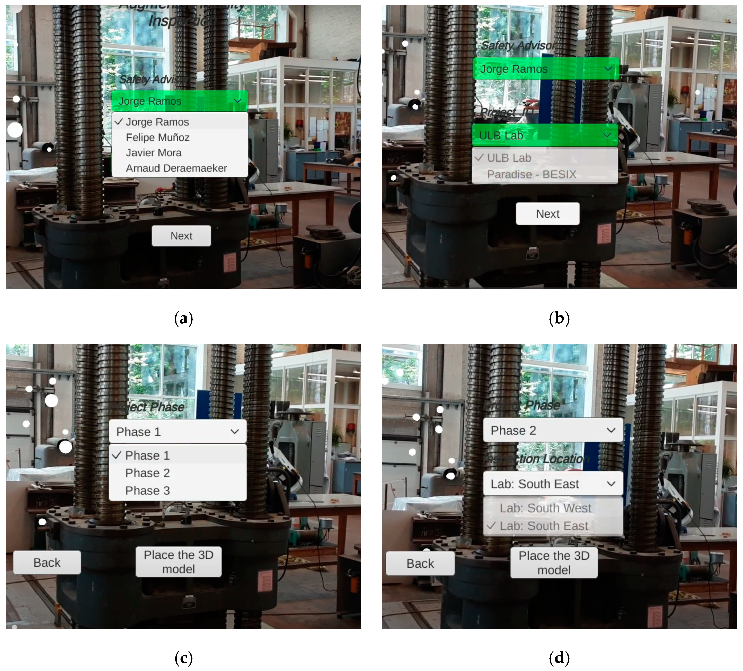
Figure 6 shows the UI screens of the proposed application. In the first UI (
Figure 6a), the input mentioned in
Table 6 is used. A dropdown menu for all the options is designed to avoid having to manually type out the information, so as to accelerate the procedure and improve the user experience (UX). The data input is automatically fulfilled following the date of the inspection. This second UI screen (
Figure 6b) inputs the data regarding the project phase and the zone that needs to be inspected. Only the elements according to those data are shown in the app.
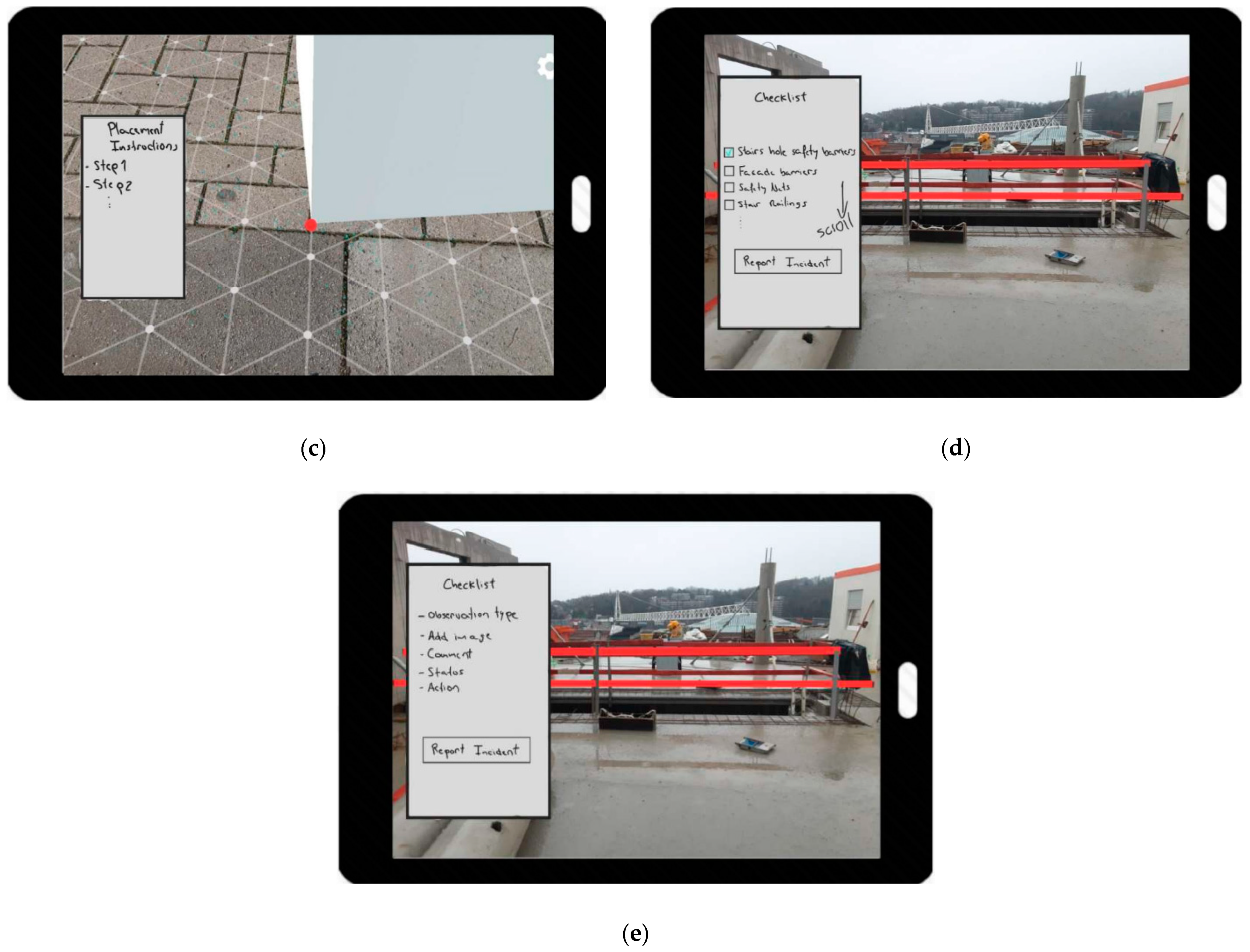
In the third UI screen (
Figure 6c), the 3D BIM model is placed. There are several techniques to place the model. Damià [
68] placed the model using the GPS coordinates, whereas Ramos-Hurtado [
69] placed it by scanning the horizontal floor and using two points of reference that define the location and the orientation. In ARCore, the default option is to scan the horizontal plane, tap one point of reference, and orientate the model manually. As mentioned, the precision of the model placement depends on the technique used and the device specifications. In this third UI screen (
Figure 6d), the checklist of the CPE can start. In this case, a panel appears with a list of the items to be inspected. If an incident occurs regarding safety aspects, the UI provides an option to report it. In the other UI screen (
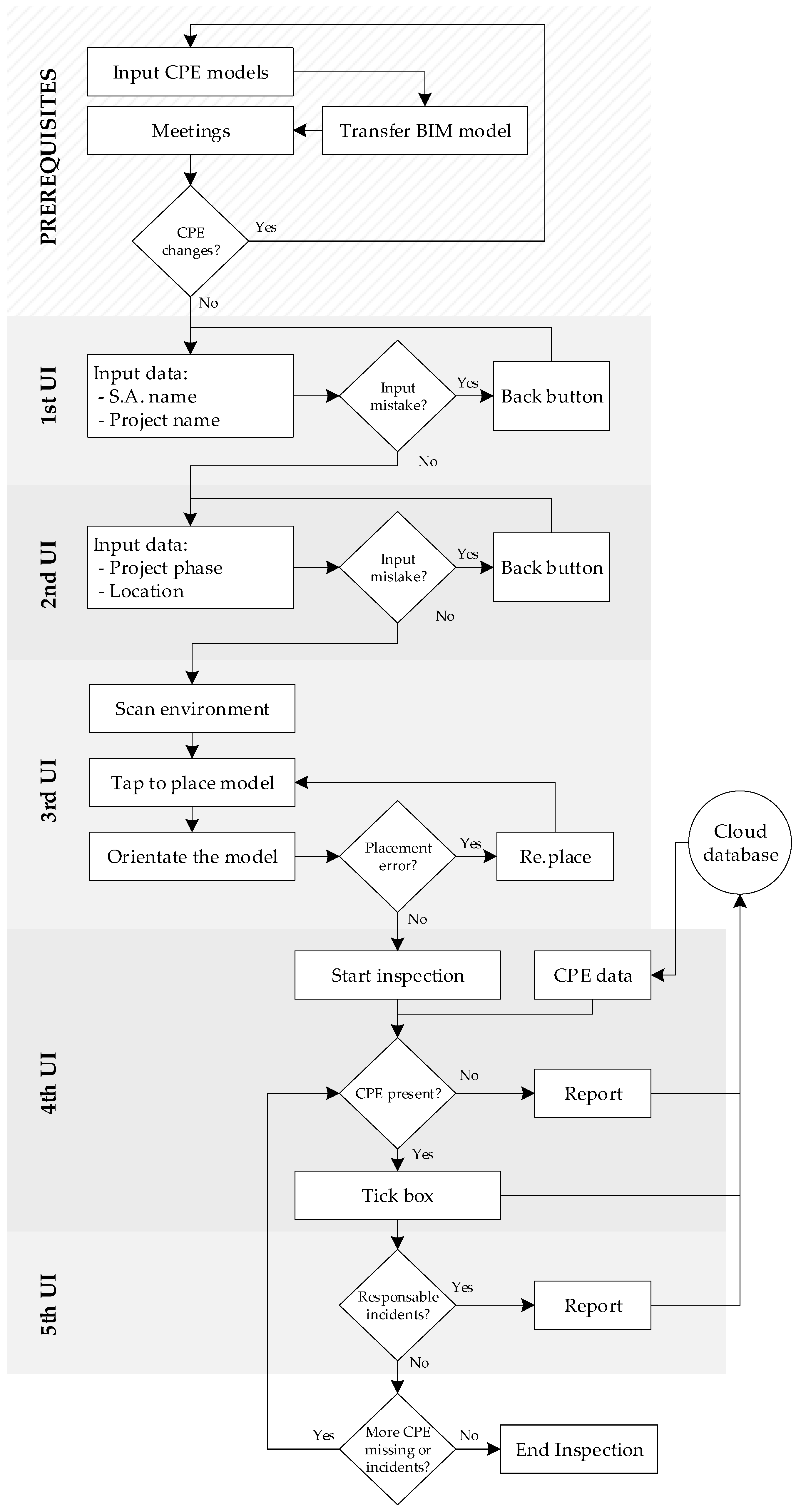
Figure 6e), the report panel is shown to fill the fields used in the safety reports. These fields are the observation type, add image, comments, status, and action. Once the inspection of the elements is completed, a button can be pressed to finish the inspection, and all the data should be transferred to the cloud database.
Once the application’s design is completed, the specific workflow of the app to be used by the SA is defined (see
Figure 7). In the following section, the application’s workflow and how it is integrated into the inspection is described.
6. Development of the Application
Using an illustrative example, this section outlines a specific step-by-step development procedure to satisfy the detailed requirements and conceptual design described in the previous sections. This procedure can generate many other contents with different scenarios and elements. The established algorithms and procedures enable the development of a similar application for other BIM models which consider the changes in the security elements and the specific characteristics of the project.
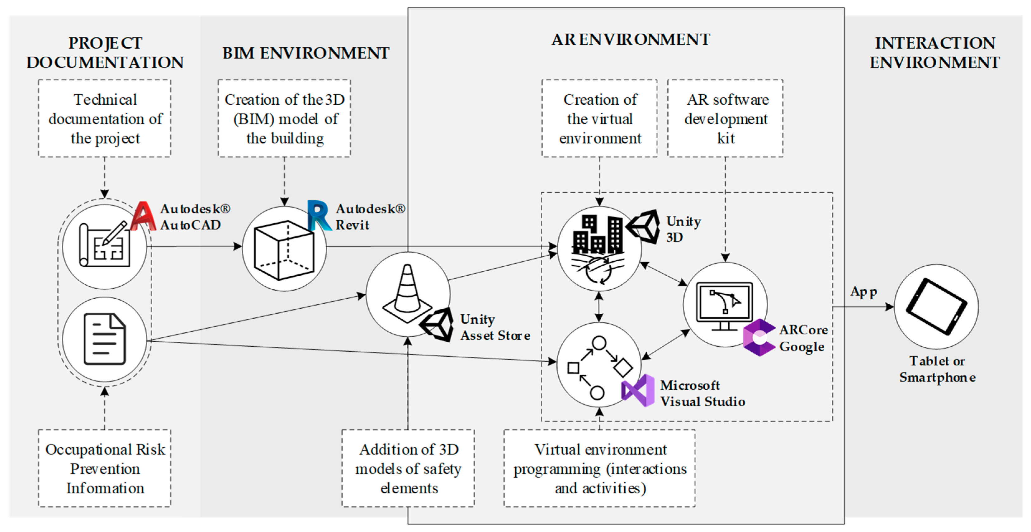
Figure 8 shows a workflow to create the contents for the augmented reality application. For each deployment phase, the required software and devices are indicated and described (see
Table 8).
6.1. Creation, Import, and Configuration of Models
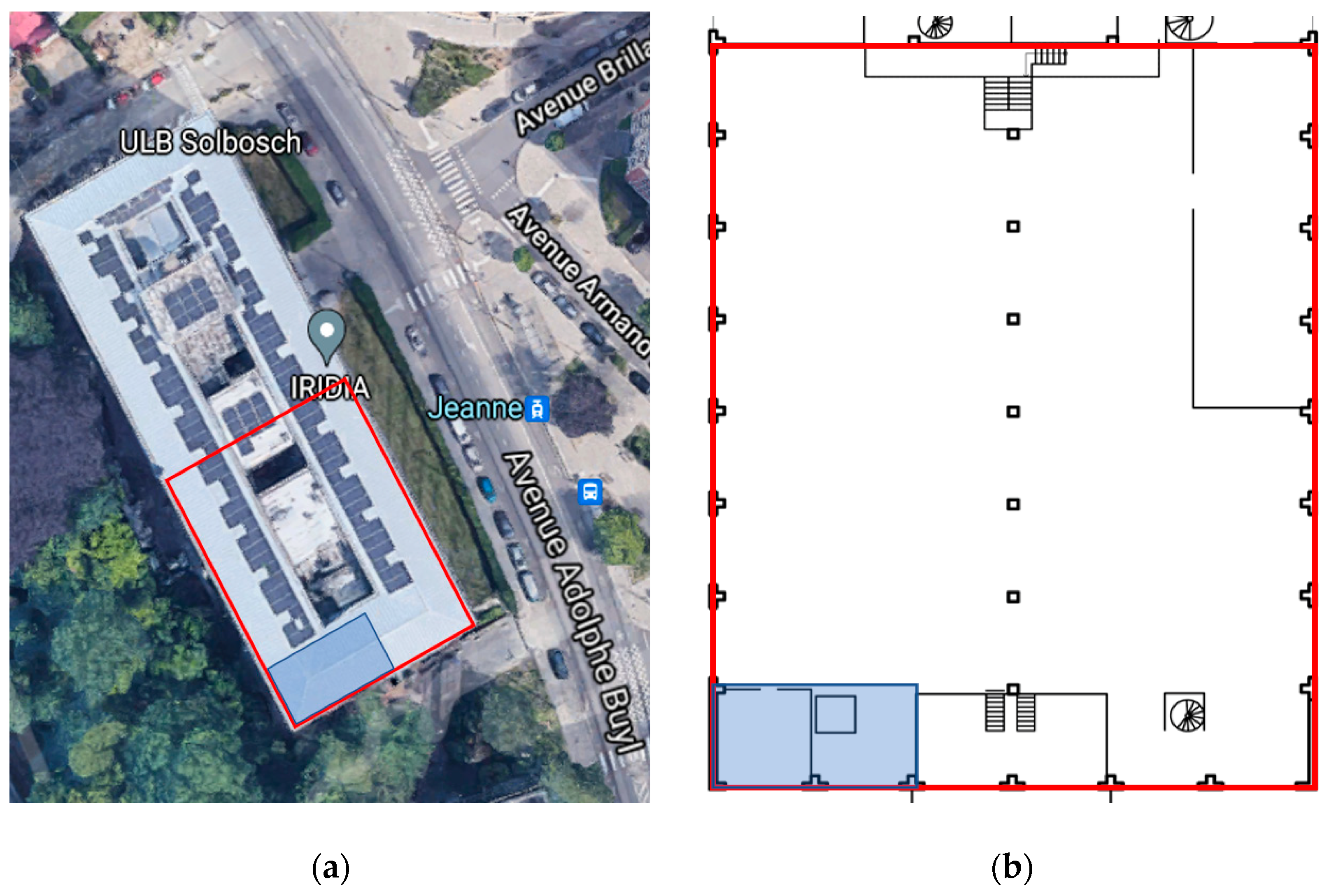
The specific implementation of the application is carried out to inspect the safety elements in renovation work on a civil engineering laboratory building at the Université Libre de Bruxelles (ULB), located in building C at the Solbosch Campus, Brussels. The correct planning and presence of the safety elements should consider the operations performed at the laboratory and the protection of the testing machinery located there.
Figure 9a shows the location of the laboratory at the university campus.
The first phase is devoted to creating the BIM model of the construction site. A 3D model must be mixed with the real environment using the AR app. Given that there is no BIM model of the ULB lab, it should be created according to the technical documentation of the project and the AutoCAD 2D drawings (
Figure 9b). The BIM software used to model the lab and the construction simulation is Autodesk Revit. The 3D model created includes the building itself and its components and accesses building information from the model’s database and on-site photos. The structural elements are modelled with the columns, walls, and the floor, but without non-essential elements to avoid a heavy model in terms of memory size.
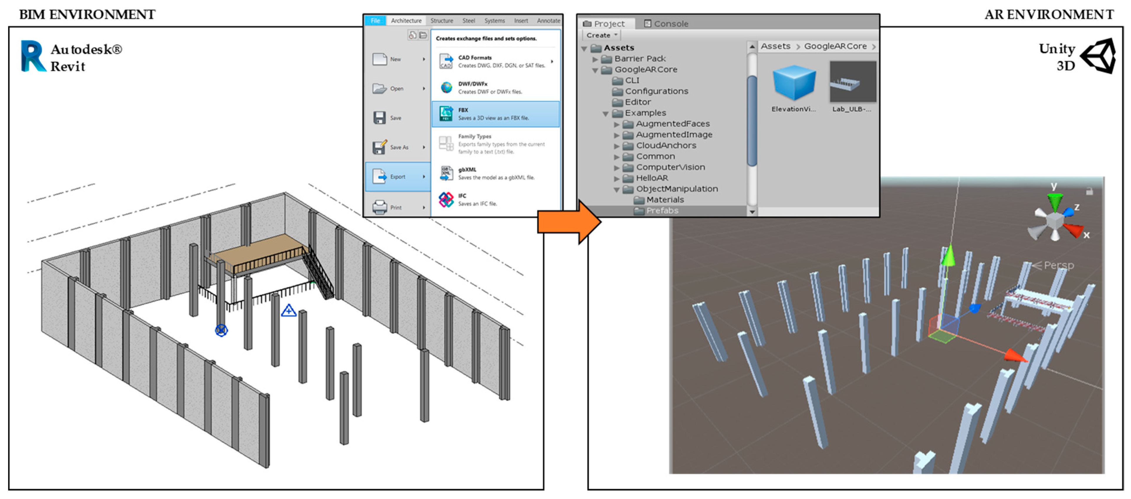
The 3D model of the construction built in Revit is detailed in
Figure 10. Once the model is completed, it can almost immediately be exported to the Unity 3D development framework. This 3D model is transferred by using the FBX 3D data interchange format, which is the most appropriate for Unity.
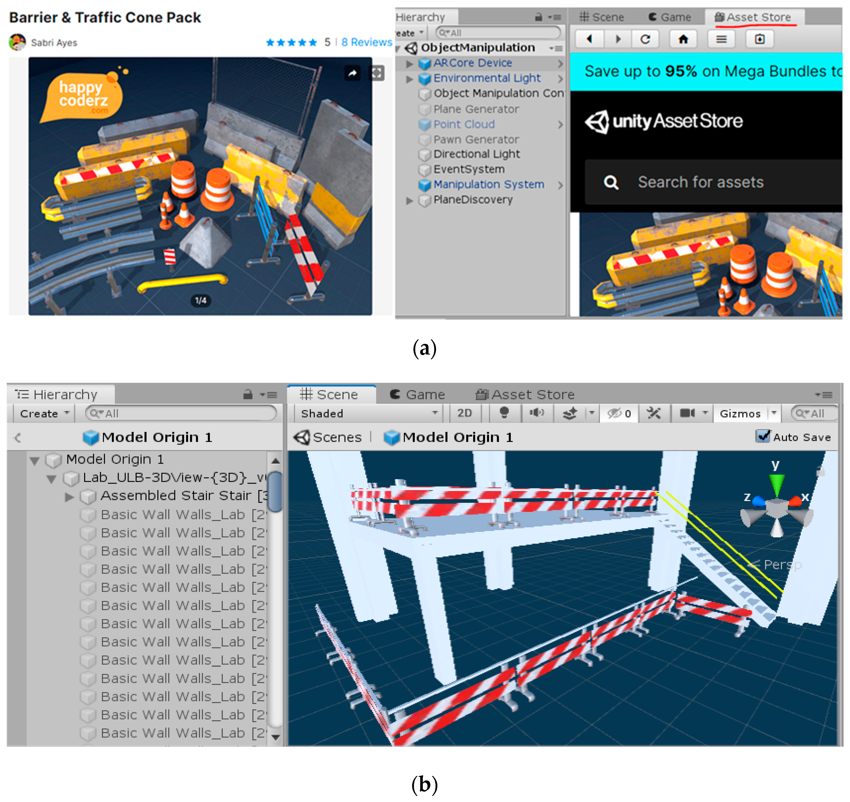
One of the goals of the AR app is to provide an easy and direct visual comparison between the virtual model of the CPE and the real CPE. These CPE models can be created in Revit or any other BIM environment as the building was created, and then exported to the Unity development environment. Still, it can also be completed by using libraries directly in Unity. In this project, the CPE are introduced from the Asset Store of Unity, where many 3D safety equipment models are available (
Figure 11a). The CPE models are then uploaded to the Unity project and placed in the corresponding zones on the building. For example, the barriers of the construction simulation are placed on the slab edge of level 1 and level 0, covering the area of the construction. In addition, some railings have been added to the stairs. The enrichment of the 3D model with this safety equipment is shown in
Figure 11b.
To set the phase where this equipment belongs, a script called Object_Information (Algorithm 1) is created with two parameters to define the phase and checking state for each CPE, which helps to validate the CPE status at execution time.
| Algorithm 1 Object_Information |
| 1: | using System.Collections; |
| 2: | using System.Collections.Generic; |
| 3: | using UnityEngine; |
| 4: | using UnityEngine.UI; |
| 5: | public class Object_Information: MonoBehaviour |
| 6: | public string PhaseParameter; |
| 7: | public bool Check; |
| 8: | public void SetParameters(string PhaseParameter) |
| 9: | this.PhaseParameter = PhaseParameter; |
| 10: | public void CheckParameter(bool Check) |
| 11: | this.Check = Check; |
| 12: | public string getSetParameters() |
| 13: | return PhaseParameter; |
This code is easily added to each element at the inspector window in Unity3D, where the properties can be accessed. Once all the 3D models are configurated in Unity, the AR environment should be set to manage the placement and visualisation of the elements, and to register the UI’s information to be managed by the SA.
6.2. Development of the Augmented Reality App
This section describes the components needed to create the Unity app and the process to develop the code and algorithms to cover all the functionalities already defined by means of the different levels of the user interface.
The core elements to develop an AR app for Android can be included in a Unity project by downloading and installing the ARCore SDK [
70]. Once installed, the Unity project window will contain several folders with the AR components and examples of complete AR applications, which makes it easier to become acquainted with the workable environment. These examples include several assets which are practical functions for developing an AR app and can be reused for the establishment of a specific app.
For the purposes of this project, one of these examples is used to establish the essential functions, such as the plane detection on the real environment and the placement of 3D objects in those detected planes. It is important to consider that these functions are created using several coding programs that are already ready to use. The example chosen for application is the Object Manipulation scene. Each function of the components is briefly described in
Table 9.
To place a 3D object in a plane detected by the device, it is necessary to select a reference point or point of origin to anchor the BIM 3D model. This point of origin would need to be easily visible in the real environment to detect the planes accurately around that point. This procedure can be completed in Revit by modifying the Project Base Point, which maintains the origin in the FBX file. Another option is to change it in Unity3D. This is done by creating an empty game object in the hierarchy. Then, in the inspector window, the coordinates are adjusted to the origin of the coordinates system. Once the game object is set, the BIM 3D model is moved to place the new origin desired at the origin of coordinates. Then, the BIM 3D model file is dragged into the empty game object to make it a child of the element. The result is that the BIM 3D model is set on the origin of coordinates at the desired point.
It is important to note that changing the base point of the project in Revit (or in any BIM environment) will change the georeferencing of the project. This aspect could cause problems in project management if this type of information is associated with elements of the model. On the other hand, modifying the base point of the model in the augmented reality development engine (in this case, Unity3D) does not generate these problems (as long as the BIM-RA environments are not interconnected). For this project, the management of the models is based on text information (for example, the level where the EPCs are located); therefore, the change in the base point does not affect the model.
The next step is to place the 3D model in the AR environment. The default option of ARCore is conducted by the following piece of code, which places the BIM 3D model according to a point previously selected in the real environment.
The procedure works as follows: first, reading the coordinates of the point selected in the virtual plane from the real environment; second, checking whether the point belongs at the front of the plane or at the back. If the point is at the back of the plane, a debug message is shown, and the model is reversed. If the point is at the front of the plane, as it would be expected to be, this code (Algorithm 2) changes the model’s origin coordinates to the coordinates previously read from the tap input.
| Algorithm 2 BIM 3D model according to a point previously selected in the real environment |
| 1: | if (Frame.Raycast(gesture.StartPosition.x, gesture.StartPosition.y, raycastFilter, out hit)) |
| 2: | //Use hit pose and camera pose to check if hittest is from the |
| 3: | //back of the plane, if it is, no need to create the anchor. |
| 4: | if ((hit.Trackable is DetectedPlane) && |
| 5: | Vector3.Dot(FirstPersonCamera.transform.position—hit.Pose.position, |
| 6: | hit.Pose.rotation * Vector3.up) < 0) |
| 7: | Debug.Log(“Hit at back of the current DetectedPlane”); |
| 8: | else |
| 9: | //Instantiate game object at the hit pose. |
| 10: | var gameObject = Instantiate(PawnPrefab, hit.Pose.position, |
| 11: | hit.Pose.rotation); |
The different application UIs are created once these previous steps are completed. The following sections describe the configuration and organisation of the UIs inside Unity, each UI’s creation, and the codes used to configure the different functionalities. When creating a UI in Unity, there are two options: creating a Unity scene for each UI or creating all the UIs inside the (only one) scene. For demonstration purposes of this work, the second option is selected.
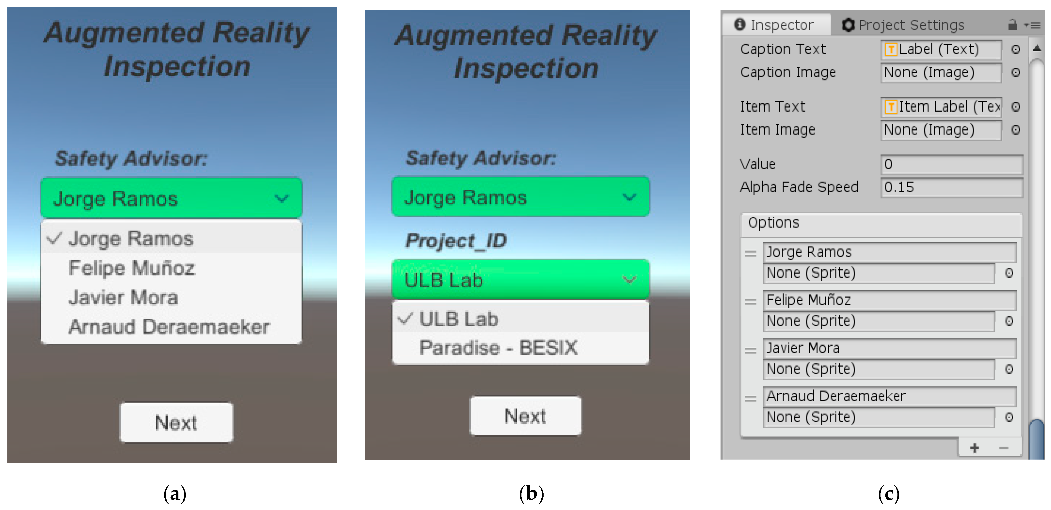
6.2.1. First User Interface Level: Input of Basic Information
This UI design consists of the safety advisor’s name and the construction project name as inputs. In
Figure 12, a view of the dropdown menu and the options that can be added in the inspector window can be observed: first are the two dropdown menu objects with both fields, and second is the configuration setup. As much as possible, the app is provided with default values or information before the inspection in order to save time at the test site.
Once the dropdowns menus are set, a button that introduces the second UI is created. The managing of the functions to disable the first UI and to enable the second is carried out via a specific script. It can also be done by using the OnClick function located in the inspector window, given that the different UIs are organised in packages. This second option allows one to select the objects that can be set as active or not when clicking it. Once all the functions of the first UI are created, the second UI can be developed with similar UI elements.
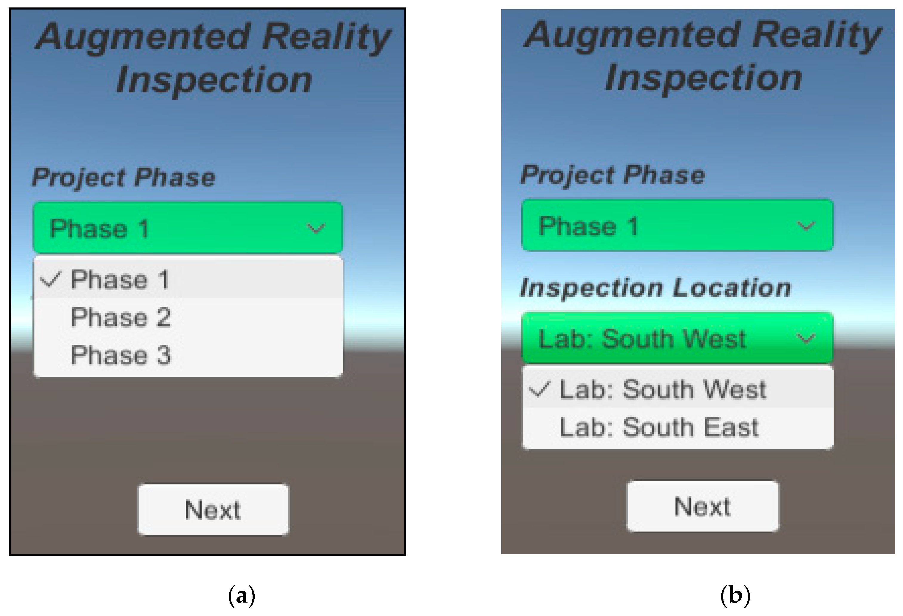
6.2.2. Second UI Level: Input of Inspection Data
The second UI is designed to input the data regarding the inspection. The project phase is a variable linked to all the objects belonging to that phase, the location of the inspected area, and the safety equipment related to that location. The creation of these elements is done in the same way as in the first UI, where the distribution of the elements is shown in
Figure 13.
For this prototype, there are three project phase options, whereas there are two options for the inspection location. In terms of the app’s development, having different scenes depending on the project phase or location is important for avoiding a heavy 3D model, which can be difficult to manage in many of the current devices. For this particular demo, due to the small size of the construction simulation, the inspection can be completed at one time. In this UI, the next button has the same code and configuration as the equivalent one in the previous UI, with the only difference being that this time the second UI is deactivated, and the third UI is activated. This button also activates the game objects that run the AR functions.
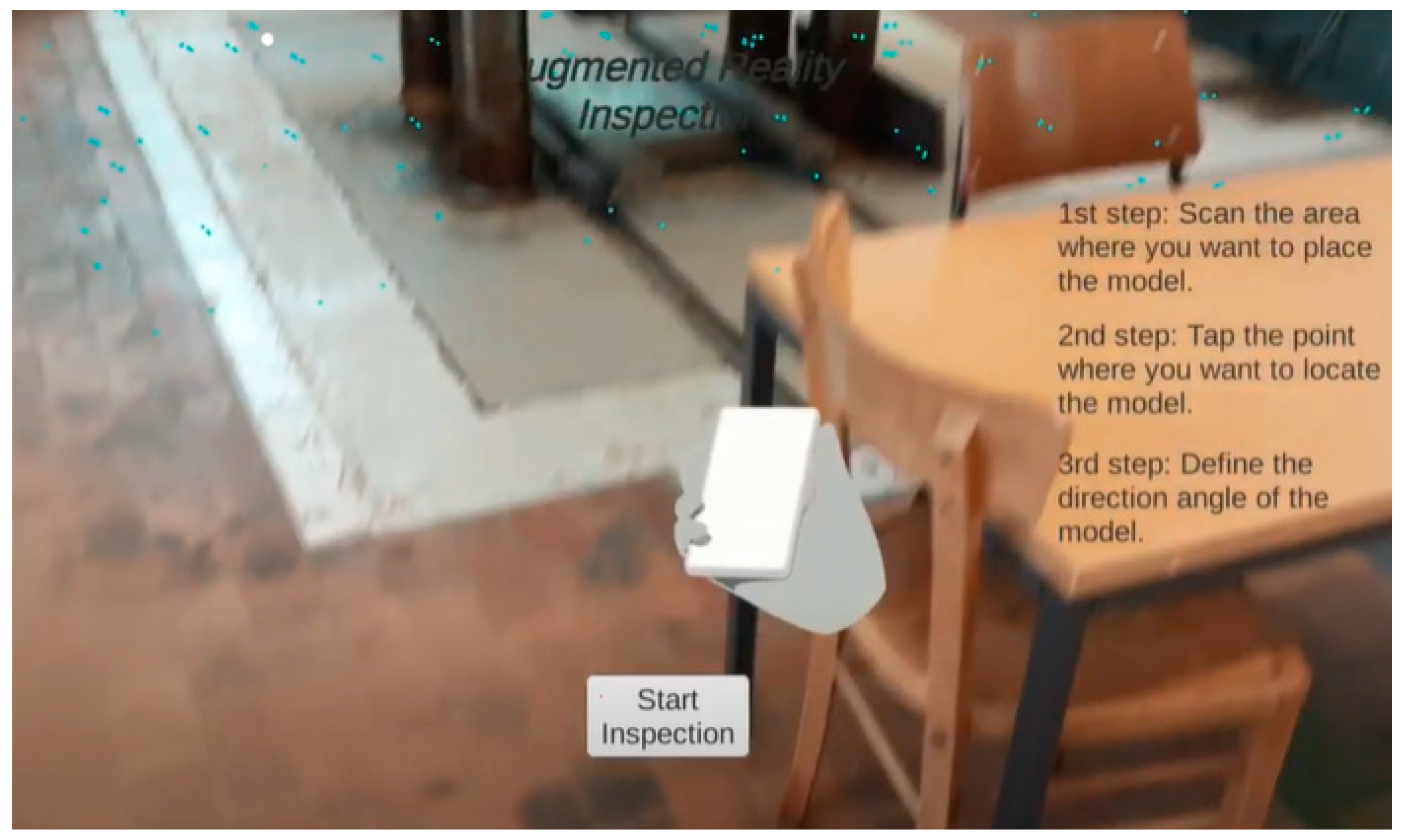
6.2.3. Third UI Level: Placement of BIM Model
The third UI is designed to handle the 3D model (see
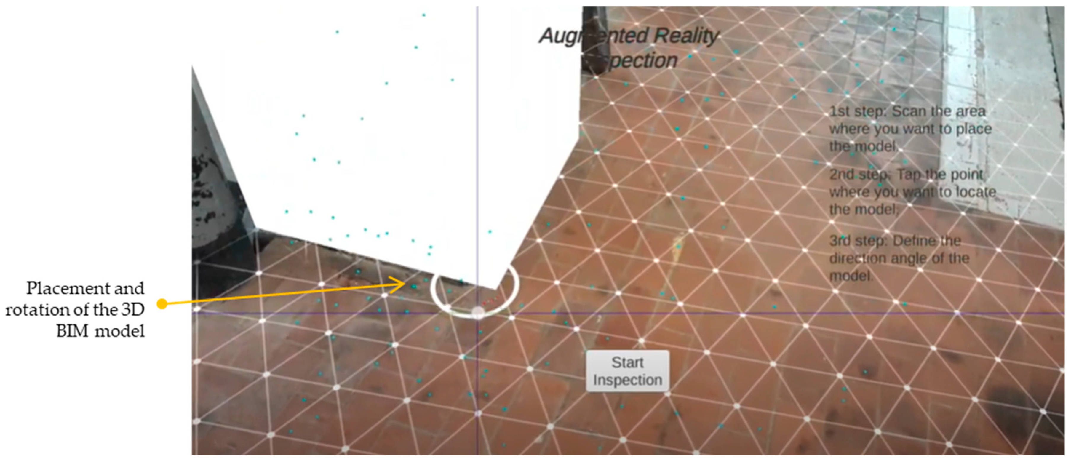
Figure 14). The following steps are provided to the user to correctly locate the virtual model in its real place: (1) scanning the floor plane; (2) tapping the model point of origin in the real environment; and (3) rotating the model to fit with the right position.
The AR functionalities are activated with the next button of the second UI, which makes it possible to place the model at the beginning of its appearance. Furthermore, to help the user, a hand animation GIF is provided to let the operator know that it can start scanning the environment. Afterwards, the app starts scanning the environment internally and creates a mesh of the detected planes. Once the desired plane is created, the user can tap the point of origin to place the model. Finally, once the object is placed, the user can rotate the model to its desired angle.
It is important to note that the level of accuracy of the meshing performed by the application will depend on the characteristics of the device being used. In the case of tablets, the accuracy is low. However, for this application, high accuracy is not required. The user must try to correctly select the base point defined for the model. However, millimetre-level accuracy is not needed since the objective is to position the CPE. The correct placement (joining of elements at specific points, for example) will depend on the SA review. Thus, for these functionalities, aspects of the model’s georeferencing and the scanning performed by the tablet do not represent a problem since the model is positioned concerning the point defined by the user, not concerning a georeferenced point. Suppose georeferencing was necessary (for other types of functions): in that case, aspects such as the accuracy given by the equipment used and the quality of the GPS signal inside the building, for example, must be considered.
This UI includes a button to start the inspection, which activates the following fourth UI: the checklist of the CPE. This same button deactivates the current UI and AR features.
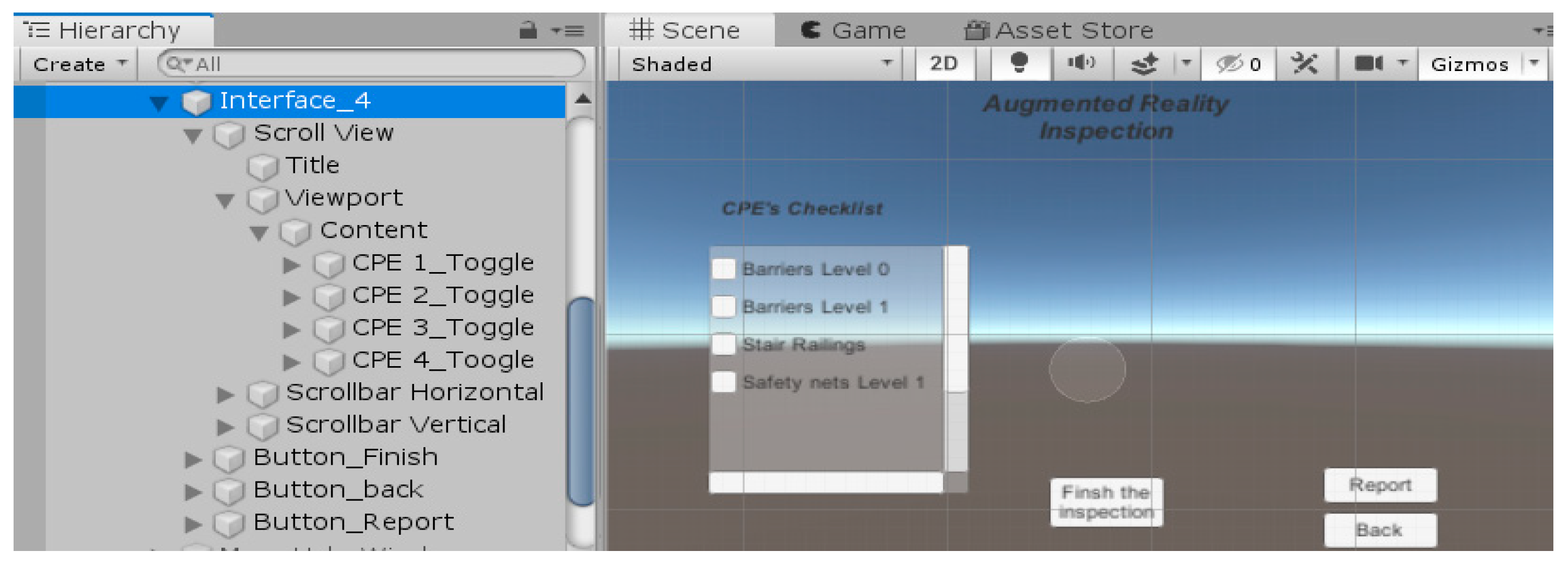
6.2.4. Fourth UI Level: Initiate Checklist
This UI belongs to the inspection of the elements with a checklist. The Unity objects for this UI are as follows:
Scroll view: the framework that contains the list of the CPE.
Toggle: checkbox element containing the CPE names and a check parameter that can be read with a script.
Report button: changes to the report UI.
Back button: changes to the previous UI.
Finish inspection: it finishes the application and saves all the information regarding the checking.
With these (unity3D+AR) technologies, the more efficient way to introduce the CPE’s Unity objects in the scroll view is to prepare and run a script that includes all the CPE and reads all their parameters. These inputs can be automatised at a higher level by creating an importing code that reads the data directly from the BIM model. In this case, since the construction simulation is small in size, these inputs were introduced manually in Unity. These contents were included as toggle objects in the inspector window of the scroll view object (see
Figure 15).
6.2.5. Fifth UI Level: Reporting
Once the inspection is completed, the checklist and any additional information should be packaged as a report. The fifth UI contains all the elements to report the potential incidents. This reporting includes five types of inputs depending on the observation type, incident image, comments, status, and action. The objects created for this UI are as follows:
Text: containing the title of the different fields.
Input field: this allows you to type in a different field.
Camera button: this allows you to take a picture of the incident.
Save report button: saves the report with the fulfilled parameters.
Back to inspection button: returns to the previous UI to continue the safety equipment inspection.
Since the reporting can greatly change depending on the quality protocols of each company, this work has been focused more on the available tools and procedures rather than on a complete and specific report with all the fields.
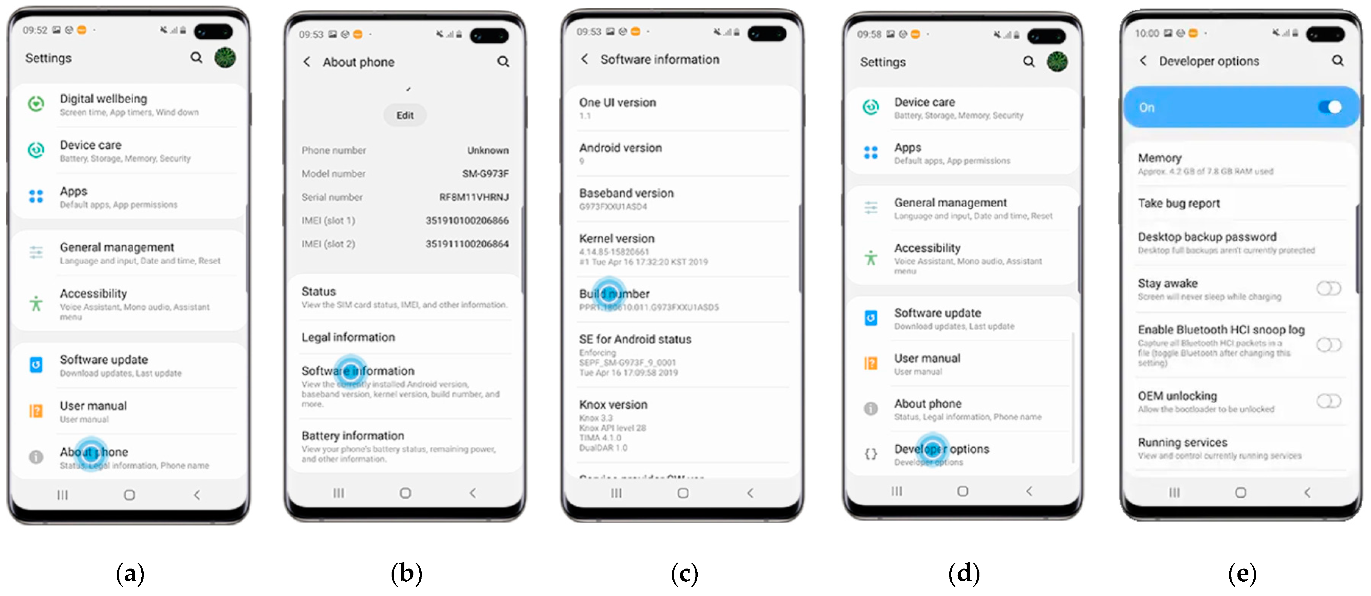
6.2.6. Launching the App
As it is still in the development phase, this app is not yet available to the public, so the developer mode in Android is required, and the connection to the smartphone or tablet is established via USB (see
Figure 16).
At the project settings of the Unity environment, just two fields are required to define the app. The company and product name is the name that will appear in the device app icon. Once this is completed, to launch the app, it is necessary to compile the models and codes by going to the Files/Build and Run tab. The resulting files should be transferred to the device and the APK saved into the desired folder.
6.3. Final Application Developed
This section describes the real-time validation of the app’s functionalities, which are to have the final specifications, key performance indicators, and possible improvements.
In the testing of the first UI (
Figure 17), the inputs are reasonable in size, and the required steps are easy to follow, which makes for a pleasing user experience (UX). When testing the dropdown menus, the ease of introducing these inputs rather than typing them is sensed.
In the second UI (
Figure 18), the user experience (UX) is relatively similar to the first UI, as the input type is similar.
The third UI requires more care because it validates the AR features and is much more dependent on the kind of device used (in this case, the device used is shown in
Table 7).
The detection of the planes was relatively rapid and straightforward.
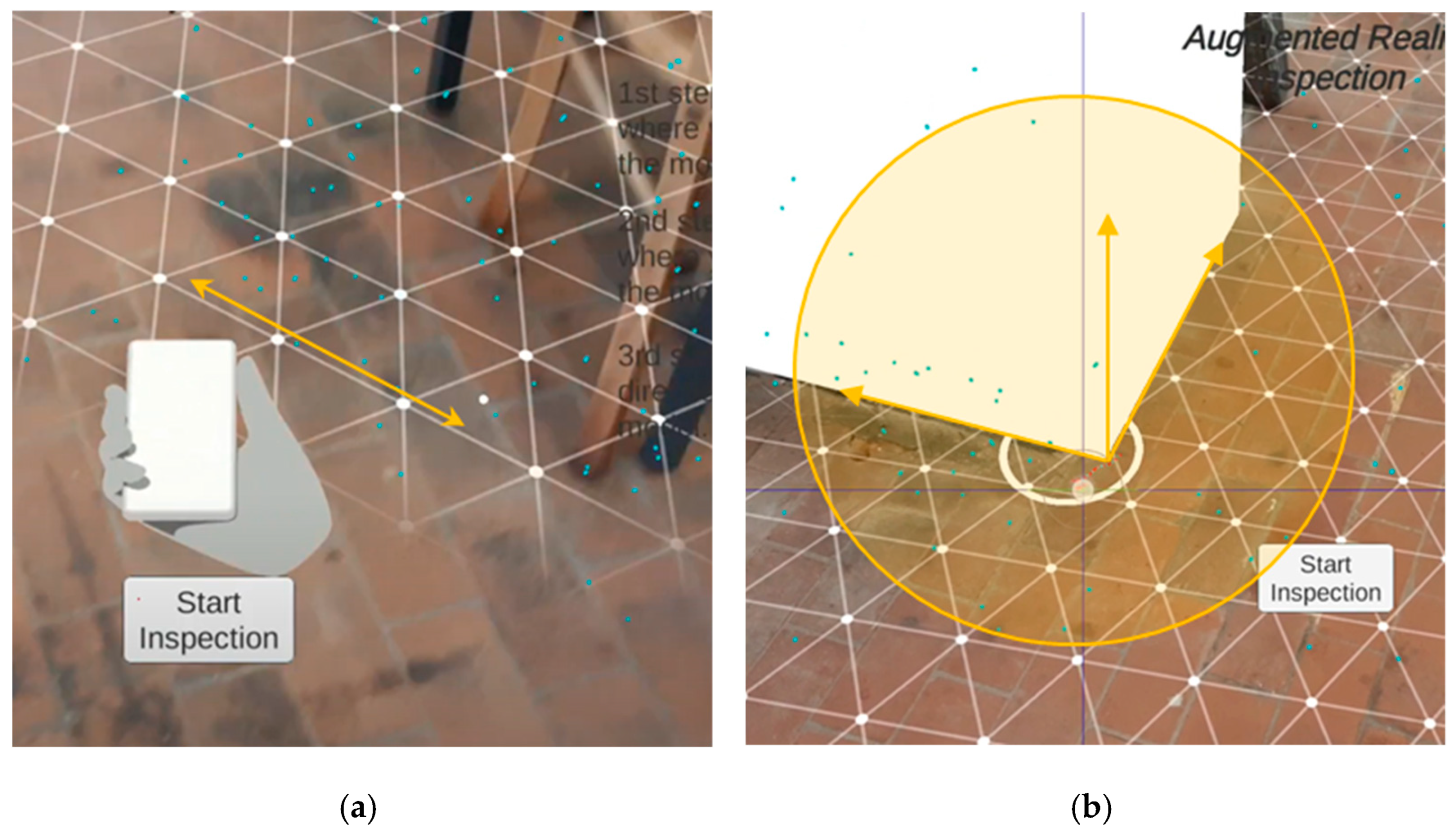
Figure 19 shows the scan of the planes along with the three-step guide to mix the real scene with the 3D model.
The handling of the model (see
Figure 20) is easy and intuitive. The default origin is located at a corner of one of the columns. The model can be rotated with the aid of a circle illustration, which allows you to tap and drag to the desired position in a similar vein as the UI for CAD software. This UI includes a button that initialises the following (fourth) UI to start the site inspection. Two additional controls (back and replace switch) can be used to undo actions if the model’s placement is incorrect.
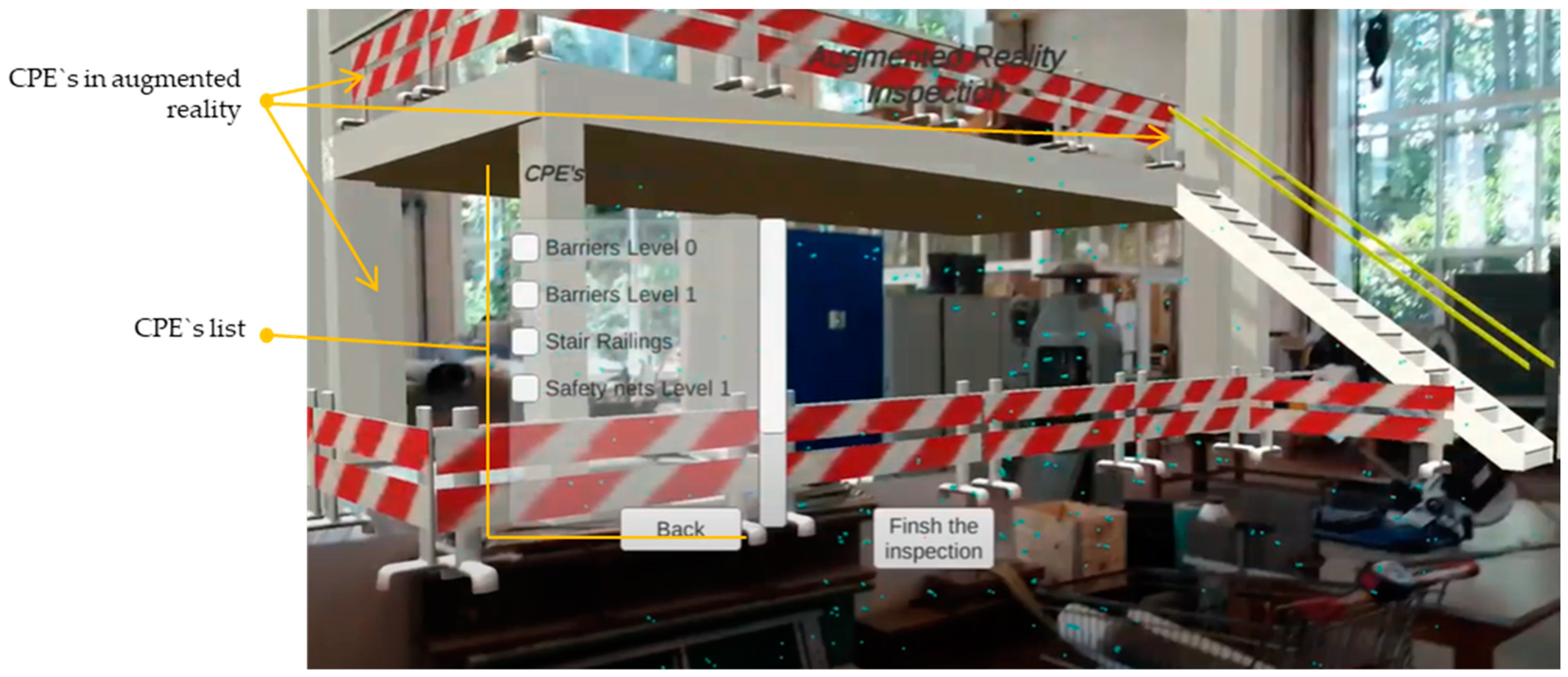
The CPE item list makes inspection easy, as expected (see
Figure 21). The UI elements, such as the scroll bars and the values according to each phase of the inspection, are key to finding the optimal balance between all the information necessary to verify each element. Still, there are not too not many elements, so as to avoid wasting time looking for each box to verify in the app. In accessing the information regarding the CPE, a tap on the element name should trigger a panel with the desired information previously introduced in the BIM software.
According to this preliminary lab test, it is important to consider the following key points when developing an AR app for this kind of purpose:
The development must be iterative so as to obtain a fluid and intuitive interface that is adapted to the type of inspection, user profile, and information to be collected, such as the inputs of the safety advisors, project name, and CPE elements.
The model placement is not as immediate as expected, and requires changes due to issues such as the potential impracticality of the origin point depending on the choice area.
The main priority of the application, over and above the inclusion of data, is to ease the checking of the CPE by visualising them in AR.
7. Concept Proof Assessment
As a result of analysing the inspection methods and applying the methodology and recommendations proposed in this research, an application has been developed. This app is a concept test to assess the feasibility of the proposed method, the practicality of the recommendations provided, and the functionality of the incorporated tools. The app must respond to the CPE inspection requirements obtained in the first stage of the research. Three types of assessment were performed: an assessment of the user experience, an assessment of KPIs for the application’s performance (qualitative and quantitative), and a comparison with the traditional inspection method. These assessments are then aligned to the relevant aspects considered for occupational health and safety, according to ISO 45001 [
71].
7.1. User Experience (UX) Internal Assessment
The user experience includes all the users’ emotions, beliefs, preferences, perceptions, physical and psychological responses, behaviours, and accomplishments that occur before, during, and after use of the app. In this case, the application tested in the lab has been internally evaluated, with a focus on the perception of the functionalities and the AR environment. Other possible requirements in terms of UX have been identified and proposed as part of a continuous improvement cycle. These aspects are classified as follows.
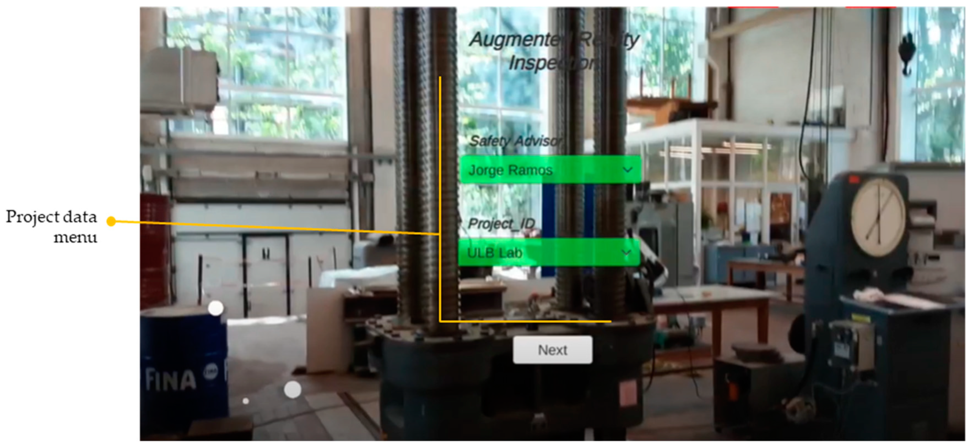
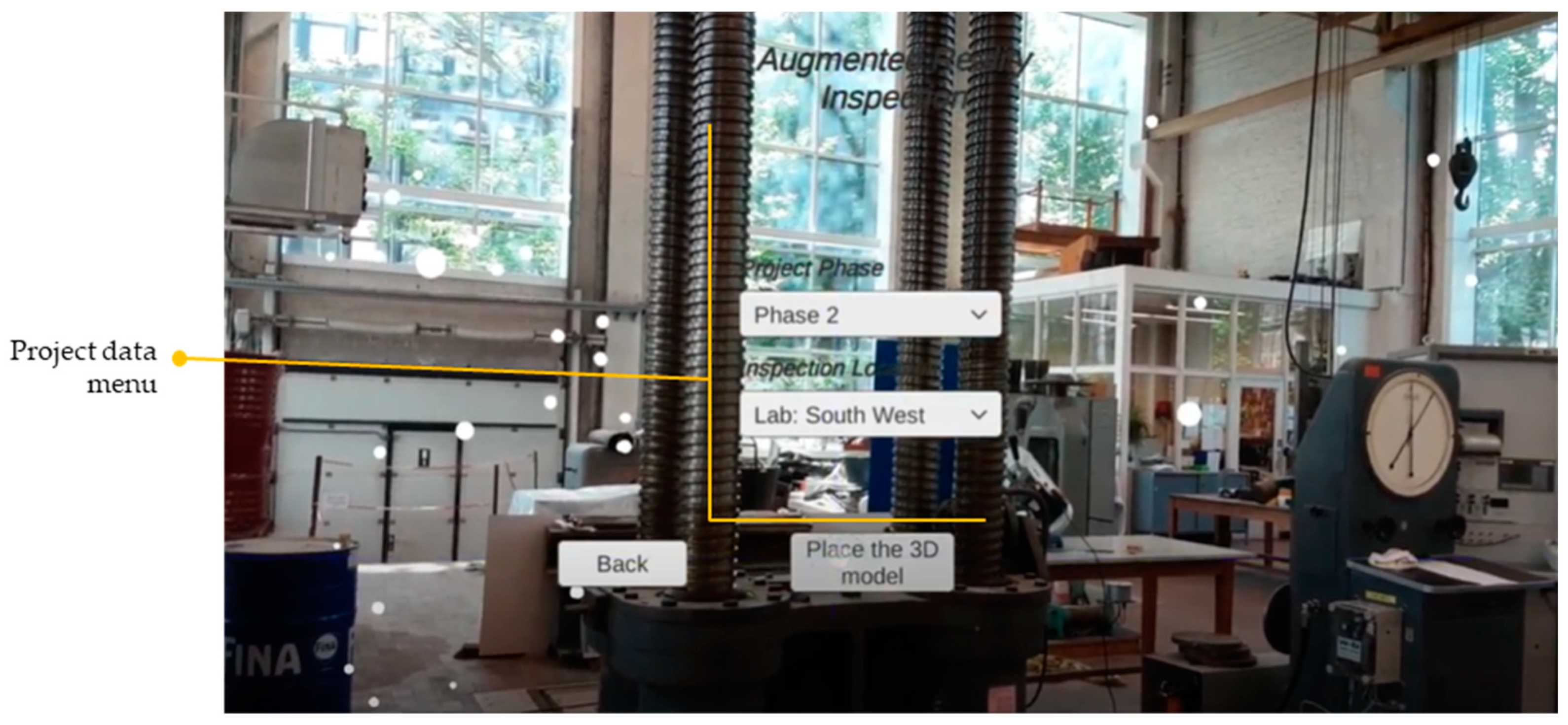
7.1.1. Input of the Data Regarding the Inspection
The input information introduced in the first UI is the name of the safety inspector (
Figure 22a) and the name of the construction project (
Figure 22b). These data are submitted by typing each letter on the input box. To save time during the inspection itself, the UI input was substituted with a dropdown menu of the inspector’s name (to be introduced beforehand when the inspection is planned). In this way, the application allows you to enter the information of the project’s members and name, linked as appropriate. Similarly, other relevant information (internal company codes, for example) can be incorporated into the user interface, either manually typed (which may not be efficient for a mobile device application, as it is important that information is entered quickly) or with a dropdown menu.
Equivalently, the inputs of the project phase (
Figure 22c) and the location to be inspected (
Figure 22d) are indicated by a dropdown menu in the second UI, having been automatically introduced from the BIM model. The project phase is presented with a specific date linked to all the CPE elements that should appear on the inspection corresponding to that date, according to the construction plan. This information should be constantly linked and updated in case of unexpected delays in the construction processes. The location of the inspection project section is classified according to a specific building, specific area of the project, floor level, etc. The location where the inspection was performed is relevant for data management. The connection between the data and 3D models in the BIM methodology is key to project management.
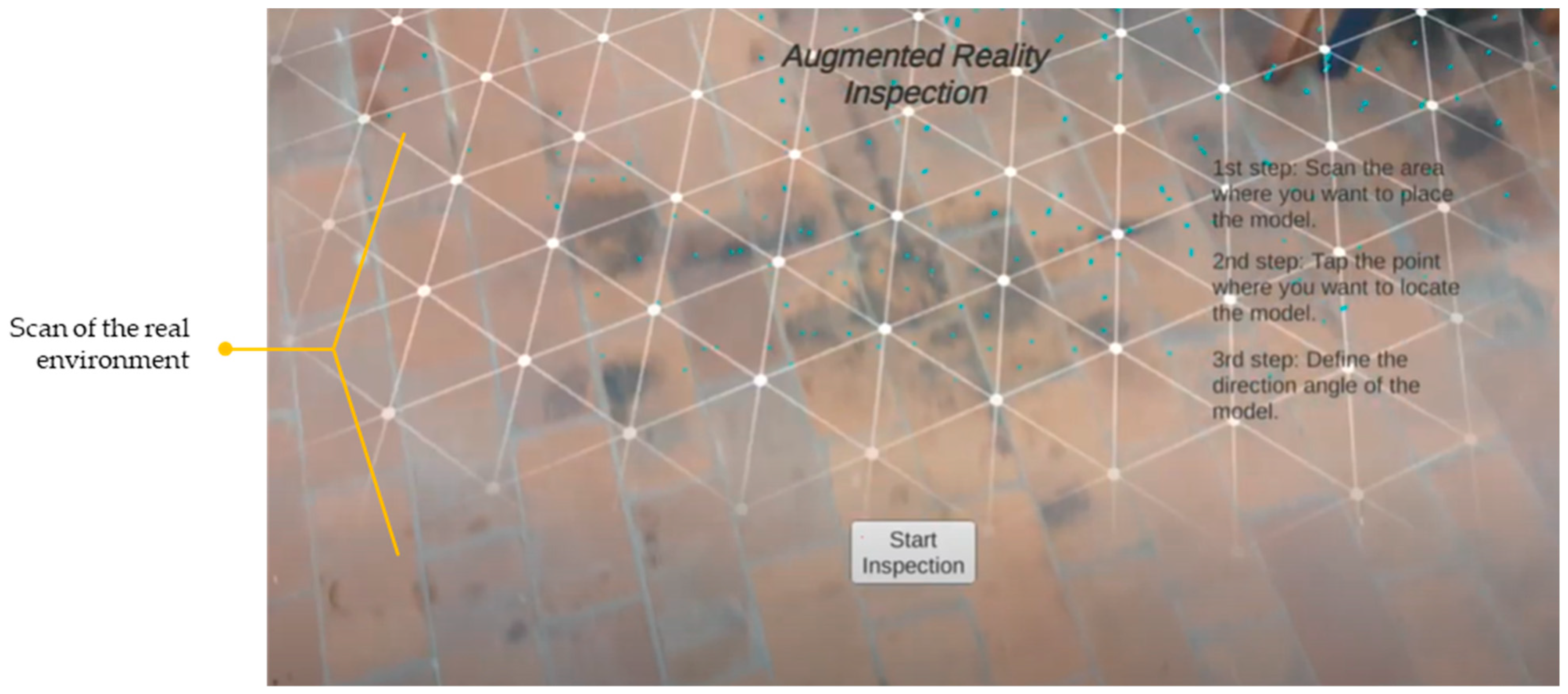
7.1.2. Placement of the 3D Model
The placement of the construction model and its safety equipment is introduced by detecting the floor plane (
Figure 23a), selecting the point of origin, and then manipulating the rotation of the 3D model (
Figure 23b). This is the most basic procedure, whereas more complex techniques are developed with higher precision. Another more straightforward option is to detect the floor plane, and by selecting two points corresponding to this plane and the model, the location and rotation can be set.
Although an important aspect is the precision with which the virtual model is superimposed on the real environment in the application, high accuracy is not required for CPE (unlike AR for surgery, for example, where precision of less than a millimetre is required). What is relevant is the correct detection of the environments to superimpose the model on the right location coordinates (x-y-z) without inclinations, and that the virtual models of the structure coincide with those of the environment (or where its construction is planned, as appropriate) so that the associated CPE are correctly placed.
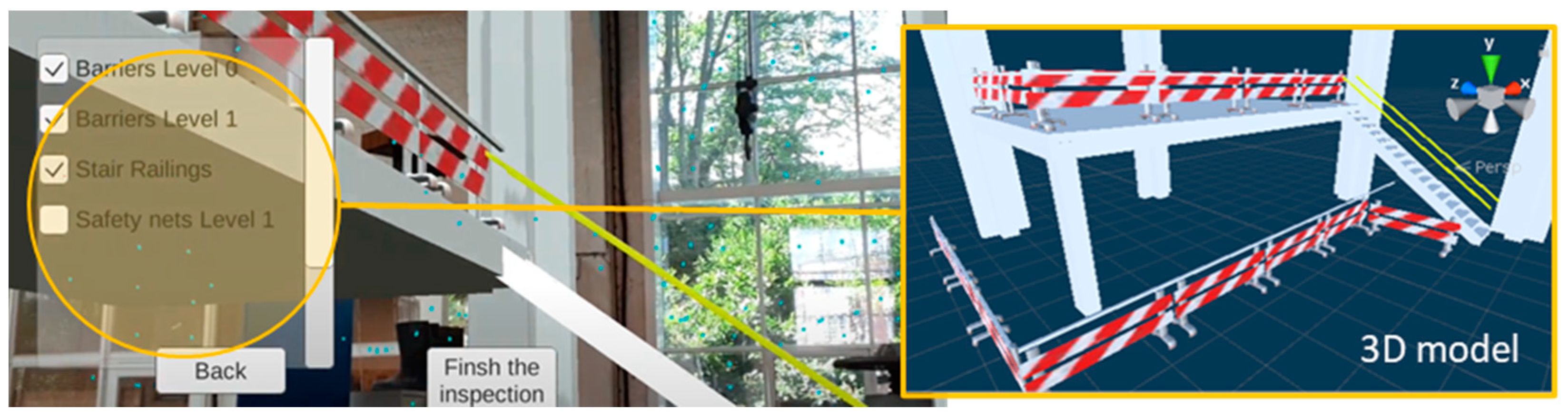
7.1.3. Inspection of the Safety Equipment
The list of elements included in the fourth UI to be inspected according to the phase and location previously provided are shown as expected (
Figure 24). All the contents can be either automatically or manually displayed by clicking the element with the desired information regarding the state of maintenance, dates of its presence, and map locations that would be automatically introduced from the BIM model.
The application developed shows the concept of itemising the safety equipment in order to visualise it in AR. It is important to highlight the potential between the information visualised as text data and the connection to the 3D models. Given the link with the BIM models, this connection is direct. Therefore, other elements can be incorporated as data or as 3D models.
7.1.4. Reporting Incidents
The fifth UI works by reporting any incidents witnessed during the inspection. The inputs of the report are those designed to be directly connected to the cloud database to be sent in real time to the project management team. This reporting is accessed in the mid-inspection, and once it is saved, the SA can resume their work. This UI has not been developed, however, given that there are already multiple available platforms with such functionality. The potential connection with platforms of this type can increase the value of augmented reality applications since such applications are generally based on photographs and data management, not the relationship with BIM models directly in AR environments.
7.1.5. Augmented Inspection General Assessment
The concept of augmented inspection refers to the digital models of the CPE to be inspected. With this proposed solution, the SA performs a direct visual comparison between the real CPE and the virtual model, which can be a more precise process in combination with the other layers seen in the AR app, and in conjunction with this, other tools such as digital rulers or computer vision algorithms can detect differences automatically. This visual comparison can greatly improve the SA’s work and help to avoid mistakes in CPE identification.
7.2. Application Performance—Key Performance Indicators
The key performance indicators, KPIs, selected to monitor the application’s performance, quantitative and qualitative, are described in
Table 10. Different aspects have been evaluated, limiting the evaluation to the proof of concept. However, these provide a notion of the performance of these applications (Description,
Table 10) and the values used in this proof of concept (Value,
Table 10).
Table 11 includes other KPIs and compares these proposed inspections with the most traditional ones, with a more forward-looking view. The comparison between the current inspection and the RA inspection considers three indicators: time consumed; robustness; and incident responsiveness. This comparison is based on the workflows of the current methods identified in the first stage of this research.
As can be observed, the KPIs of robustness and incident responsiveness are improved when the proposed AR inspection is compared to the traditional inspection. The robustness is enhanced due to the extra aid that AR provides in identifying the CPE. Moreover, the improved incident responsiveness is a result of the interconnection with the cloud database, which permits the sharing of the incident reports in real time with the project management team. Security inspection processes are the responsibility of a security agent, who must determine the level of risk and identify any missing CPE. In addition, the time that this professional takes to perform the inspection is relevant since a delay could result in an accident.
8. Discussion
8.1. Improvement of Construction Health and Safety Management Processes
Employing effective health and safety protocols in the construction industry is crucial because of the high rate of accidents in the sector. However, health and safety in construction is not always given the priority it deserves. Indeed, it is typical for construction sites to prioritise time and the rapid progress of work over safety. In other words, while maintaining quality and scope, the aim is to advance as quickly as possible (especially in a sector where initial schedules frequently have to be extended). In this rush to meet deadlines, safety is often seen as a consideration that slows down the project’s progress since it is not part of the construction itself.
Therefore, in order to achieve a balance between time-sensitive goals and safety concerns, it is important for the construction sector to improve its management systems and its implementation of health and safety plans. Thus, on the one hand, awareness policies and creating a safety culture can help to encourage workers to behave safely and to care about occupational safety. However, on the other hand, greater efficiency in the placement and inspection of CPE enables these elements to be seen as part of the work, directly associated and linked to the work plans, and not as extraneous elements that delay the start or continuation of a work unit because they are not in place or are poorly placed.
8.2. Safety Inspection Opportunities with Augmented Reality
The traditional inspection method has some shortcomings that do not help the vision of health and safety integration. While information management technologies have been incorporated, the experience of the safety officer still plays an important role in the efficiency and effectiveness of inspections. There are risks associated with the SA’s criteria, time availability, and multiple tasks to be reviewed in a day. It should be considered that inspectors must constantly review the entire building. Consequently, constant inspection is necessary. Therefore, reducing uncertainty and reducing the time between inspections is relevant. In this sense, as shown in this article, augmented reality provides great benefits for construction site inspection, both for the construction process itself and for safety applications.
Chen et al. [
18] use augmented reality to improve fire equipment inspection processes due to the drawbacks of paper-based tracking. They challenge the use of non-experts in the inspection process. Hasan et al. [
31] use AR for applications in a digital twin, carried out at the prototype and laboratory level, raising the need for full-scale work. Chung et al. [
45] use AR for a facility management system in buildings to display relevant information about real objects, suggesting the need to move towards the incorporation of more complex things to identify and massify their use. Concerning these recent works, this research advances the use of augmented reality for inspection processes of collective protection elements. It provides a procedure and a tool that non-expert users can develop (with partial knowledge in these environments and with a low level of programming), opening the way to its massification in real work environments.
Several reasons have been identified that limit the use of RA in construction safety: it is considered an immature technology; lack of workers’ skills for its use and development; lack of implementation protocols; lack of standardisation in development processes. Dávila et al. [
14] suggest the need to study the adoption of augmented reality technologies, along with the factors that contribute to their massification, from a practical perspective (beyond the simple description of uses). More recently, Dávila et al. [
15] suggest that among these factors, one of the most critical that limits adoption is that they are considered expensive and immature technologies. Added to this is the complex context and dynamics of the construction sector, where there is a high resistance to change. Chi et al. [
16] suggest the need to advance research on the application of AR in the field, the connection with data of interest, and the effectiveness of the deployment of AR devices in the construction site. Specifically, in the area of construction safety, Li et al. [
17] raise the need to combine and interconnect information from AR devices with other tools and automate evaluation methods and processes, along with increasing the amount of testing and testing of functionalities in order to evaluate the effectiveness of these tools considering different parameters. Nnaji et al. [
47] consolidate the limitations and barriers to adopting technologies for building safety management. Thus, costs, training of workers, technical support, and integration into work systems are the main issues. In addition, the small number of safety use cases fail to demonstrate the benefits of its use for different specific tasks in construction. There are also no protocols that standardise the development and use of augmented reality in safety management [
19]. Given this potential and the lack of these applications to construction safety in the literature, this research has relevance because it enters into a new phase of the project. Progress has been made in providing background information for the use of AR in safety inspection processes on construction sites and in offering methodological recommendations for the development and evaluation of these applications. The evaluation performed in the proof of concept demonstrates the procedure’s reliability. It induces the reflection of potential developers who replicate the designs to evaluate the performance of their applications. Thus, this research contributes to the state of the art in the following aspects:
To provide a global vision about the potential for AR technologies (the concept), understanding AR as the visualisation layer for all the digital information that we can have on a construction project (BIM with all their dimensions).
To provide a specific implementation (detailed vision) and deployment in a real lab, to check that every single implementation detail is considered, allowing for the measurement of performance, features, and practical use by the workers.
To provide a link between the virtual and the real model, opening the door to more extensive use of BIM information at the building site in real-world scenarios, as the essence of the digital twin technology.
To provide the environment to integrate much more complex modules, such as those coming from computer vision, machine learning, and the optimisation of processes, which is already existing but in need of an interface to work with.
To apply to the specific need of improved safety at building sites, by combining the designed safety measures with the real and changing world, where every single protection measure can change hour by hour due to the inherently changing nature of the building site.
8.3. Potentials and Challenges of BIM and AR
Considering the perspectives and challenges of the construction sector, BIM has given an important boost to the industry. The collaboration and integration of people, processes, and models help to promote the interconnection of management and the project in general. Thus, the integration of safety elements with BIM models makes it more natural to see that a work package, the construction of a beam, for example, considers materials and construction processes and safety elements. Presently, the use of BIM models is widespread in offices, but the deployment of BIM information has not yet become widespread in construction sites (including the specific construction site that we studied).
Augmented reality manages to give continuity to the BIM methodology at the job site and manages to deploy the BIM models and safety elements in situ. Thus, in general, BIM+AR contributes to the solution of typical construction site problems. The extension of BIM in the construction stage, and even more, literally on the construction site (virtually), contributes to the resolution of doubts in the field, the management of construction processes, and information on materials and technical specifications, among other aspects. In the domain of safety, SAs can now use the full potential of BIM, reducing the experience variable of the inspector, which is replaced by the full deployment of BIM information (data and 3D models) on mobile devices where augmented reality applications are used.
Some challenges are important to highlight for the mass deployment of BIM+AR on construction sites. BIM models are characterised by large file sizes and have large amounts of project data linked to them. The integration of such robust 3D models is restricted to the capability of AR viewing devices (glasses or tablets). In addition, moving towards open data formats is important for deployment on multiple devices, regardless of software or hardware brands. On the other hand, the professionals in charge of developing and deploying these tools must be trained, which represents a major effort, even more so when BIM alone is not yet fully implemented at construction sites. On the other hand, resistance to change in the sector is high. Incorporating new technologies at the construction site is not easy due to the site’s characteristics (outdoors, exposed to the weather, robust materials, dirt, and large machinery, among others) and its workers.
9. Conclusions
Based on the information obtained in the research project regarding health and safety in construction, the AR implementation in the Architecture, Engineering, Construction, and Operation sector, and specifically in the occupational health and safety field, the understanding of the different platforms, and the knowledge acquired during the development of this research has led to the following conclusions.
We have been able to identify the main pain points and bottlenecks of safety inspection: the possible robustness deficit in visual inspections, the dependence on the safety advisor’s experience and knowledge, lack of control of subcontractors’ knowledge, possible bad practices among workers, lack of coordination between reporting and corrective measures, and the lack of rapid responsiveness between the safety advisor and the project management team. All these problems are much more easily solved using digital means, which facilitates extra aid during the CPE inspection, which in turn is crucial to ensuring the safety of workers. By pursuing the zero accidents goal, the implementation of an AR technological tool has been studied to augment inspection capabilities, thus achieving a more robust procedure.
Different layers of information, detailed functional requirements of the EPC, proposed user interfaces, and a workflow to perform the inspections were proposed. In addition, key performance indicators to evaluate these applications were created. A workflow suited to the AR inspection was developed. This method also improves one of the current methodology bottlenecks: the timing between reporting and taking corrective measures. Furthermore, this workflow preserves the main tasks of the SA during the safety inspections. The design of the application meets and exceeds the pain points of the current methodology. The basis and roadmap for developing an AR application that could be implemented in a construction company is set.
For the development of the app, it has been seen that there are several platforms available in the market. For this project, the framework Unity with the plug-ins ARCore has been used due to the following advantages: ease of use for non-advanced programmers and a strong UX that makes it easier to understand the platform’s functionality and eases the transfer of BIM models. ARCore provides several advantages for AR applications such as predefined functionalities, which help in the development of AR experiences and have been used in this project.
AR has potential in the ORP field as it can ease the safety advisor’s inspection with the main objective of reassuring the safety equipment’s presence and maintenance, thus achieving the goal of the industry, which is to reach zero accidents on a construction site. An application such as that proposed in this research offers a digitalised solution that helps the safety inspectors guarantee the presence of CPE and report the incidents that occurred on the same application, reducing the need to manipulate several things at the same time. There would be a single screen for the real elements, the virtual ones, and the items that need to be checked related to the CPE checklist UI. This increases the perception of the environment, which is crucial for detecting the safety equipment and inserting the collected data into a database with information on the building site. To summarise, the main points of improvement from the traditional inspection to the proposed AR inspection are as follows:
Higher robustness to guarantee the presence of the safety equipment, which enhances the workers’ safety.
Digitalisation of the process, which eases the tasks of the safety advisor, linked to the BIM ecosystem of applications.
Ability to report incidents in real time on the CPE and IPE.
Capacity to collect data on-site, such as pictures of the safety equipment in AR, showing the possible differences between what is planned and what is executed.
For the development of this application, approximately 400 h have been invested. However, with the knowledge acquired in this project, creating this same prototype again would take a total amount of approximately three working days, i.e., 24 h. In the case of developing a full application for use on a real construction site, which would entail including all the digital (BIM) models already created with the database of CPE elements available, it would take approximately one month, i.e., 160 h. Moreover, these hours could be greatly reduced depending on the programming experience of the developer and, of course, if the developer’s experience is on similar projects.
Future lines of research could involve the following: (1) iterate the development of the process in order to construct an app at the production level which will reassure the viability of the app’s implementation; (2) validate the application at some real construction sites in order to use safety advisors’ assessment feedback to improve the app; (3) study the automation of the CPE-based 3D model and the data introduction coming from the BIM software; and (4) automatise the development of the AR applications.


 ,
, 


