
Numerical Strategy for Column Strengthened with FRCM/SRG System

Department of Civil Engineering, University of Calabria, Via P. Bucci Cubo 39B, Arcavacata di Rende, 87036 Cosenza, Italy
Buildings 2022, 12(12), 2187; https://doi.org/10.3390/buildings12122187
Submission received: 29 October 2022
/
Revised: 23 November 2022
/
Accepted: 25 November 2022
/
Published: 9 December 2022
(This article belongs to the Special Issue Advanced Numerical and Computer Methods in Civil Engineering)
Abstract
:The use of fabric-reinforced cementitious mortar (FRCM) or steel-reinforced grout (SRG) is now recognized to be effective in enhancing the axial capacity of masonry columns when confinement is achieved. Numerous experimental tests demonstrated the symbiotic role of the fabric and the inorganic matrix. An open issue is still related to the numerical simulation. In fact, if the compressive behavior by the numerical simulation of the unreinforced and reinforced masonry columns confined by a FRCM/SRG jacket may follow different approaches. The inorganic matrix transfers the stresses from the substrate to the fabric differently, depending on the presence or absence of cracks. The fabric consists of an open grid whose yard could be differently stressed after the matrix damage because of the occurrence of a possible slippage at the fabric–matrix interface. Definitely, these aspects are difficult to numerically predict. The paper herein is devoted to the assessment of different numerical approaches for the FRCM/SRG confinement of masonry columns by considering data from the literature and varying the parameters related to the matrix, the fabric, and the masonry itself. The goal is to best fit the experimental outcomes (from different available sources) with different strategies based on a finite element (FE) modeling. The results show good matching between the experimental and theoretical curves for the different FRCM/SRG systems. The results evidenced that the accuracy of the experimental versus the numerical curves match is met for the different FRCM/SRG systems.
1. Introduction
An important part of existing structures is mainly made out of masonry. Indeed, most historical buildings consist of monumental masonry structures (churches, temples, towers, etc.), as well as most ordinary buildings. There are substantial differences that exist between monumental and ordinary buildings in terms of geometry and structural details. Various strategies for the prediction and the assessment of the structural behavior of masonry buildings by a numerical model have been developed in recent decades. Numerical models have been favorably developed and preferred over analytical approaches, given the complex mechanical response of masonry and the irregular geometries of historic masonry buildings. The numerical strategies are subdivided into four classes: block-based models (BBM), continuum models (CM), macro-element models (MM), and geometry-based models (GBM). The strategy of BBM models is based on masonry heterogeneity by the assembly of the blocks with mortar joints. Through this strategy, the real texture of the masonry structure can be described, while the individual mechanical properties can be evaluated through experimental tests on small-scale samples. In addition, by means of models, it is possible to simultaneously describe both the out-of-plane and in-plane behavior of masonry walls [1,2]. Interaction is the fundamental part of the BBM strategy; it depends on the type of interaction. In the technical literature, there are five categories: (i) interface element-based approaches [1,2,3,4], (ii) contact-based approaches [5,6], (iii) textured continuum-based approaches [7,8,9], (iv) block-based limit analysis approaches [10,11,12,13], and (v) extended finite element (XFEM) approaches [14,15]. The drawbacks of this strategy are the massive computational burden of solving the numerical model, and the time dedicated to modeling the block and assembling it [16,17,18]. The strategy of the continuum model (CM) is based on the use of a deformable continuous body. In particular, the mesh does not always have to respect the real texture but can be much bigger. Through this characteristic, the computational burden is less than that of BBM models. However, the assumption of an appropriate constitutive law that is due to the properties of the masonry itself can be calibrated through two strategies: direct approach and homogenization procedures and multiscale approaches. The strategies calibrate the constitutive laws directly on the results of experimental tests. There are two types of direct approaches in the literature. With the introduction of FE and the use of the complementary energy theorem, it was possible to obtain a solution via of minimization of a quadratic function with equality and inequality constraints [19]. Other continuum-directed approaches base their nonlinear constitutive laws on theories of fracture or damage mechanics and/or plasticity. The use of these models has been shown to be favorable for assessing the structural performance of historic monumental masonry buildings, particularly because of the limited computational demands of these models and their ease in representing complex geometries [20,21,22], churches and temples [23,24,25], palaces [26,27,28], and bridges [29,30]. The second strategy introduces a homogenization strategy that connects the structural scale model to a scale model of the material and its heterogeneities. Homogenization procedures are generally based on accurate modeling strategies of an RVE (representative volume element). In particular, the RVE must statically represent the heterogeneity of the masonry under study. Three models based on this strategy can be identified in turn in the technical literature: (i) a priori homogenization approaches, (ii) step-by-step multiscale approaches, and (iii) adaptive multiscale approaches. The first model uses the RVE technique to initially define the homogenized material properties and then use them in the structural-scale model, while using homogenized properties [31,32,33,34,35]. In the second model, the structural response is evaluated for each point in the structural model of a boundary value problem on the RVE [36,37,38,39]. Finally, in the adaptive multiscale approaches one uses, through adaptability, the material-scale model in the structural-scale one [40,41,42]. The MM strategy generalizes the structure with panel-scale behavior—in other words, as a macro-element [43]. The two main elements are pier (vertical elements) and spandrel, which are horizontal portions of the structure between two openings aligned along the height. The global behavior of the structure under seismic action depends on the panel response and, consequently, on the load redistribution given by the diaphragms [44]. In fact, the MM strategy does not predict out-of-plane ruptures and would lead to an overestimation of the capacity of the structure [2]. Moreover, in severely irregular structures, subdivision appears complicated and, in some cases, impossible. The advantages are easy discretization of the model and definition of mechanical properties. This strategy is employed through two approaches: equivalent beam and spring based. The first approach is based on modeling the masonry structure by schematization in equivalent frame models. A first model, called the POR (pushover response) method, is based on the simplified elasto-plastic relationships to describe the beam nonlinearity connected by rigid links [45,46,47]. Recently, an advanced equivalent beam-based macro-element was developed in [48] for the nonlinear static and dynamic simulation of masonry structures. The beam mechanical description conceived axial, bending, and shear deformation within the Timoshenko beam theory. The second approach is based on nonlinear springs within an equivalent frame to simulate the in-plane nonlinear behavior of masonry walls [49]. In [50], the authors developed a spring-based approach where piers and spandrels are conceived as equivalent arrangements of nonlinear springs, while in [51], each masonry facade was conceived as an integral unit, instead of one of piers and spandrels. As a result, masonry behavior is described by two vertical springs and one horizontal spring for the shear behavior of the wall. Finally, the last strategy (GBM) conceives the structure as a rigid body, the only input being the geometry of the structure and the loading conditions. Through this approach, it is possible to analyze structural equilibrium or evaluation of a possible collapse through static or film theorems, both based on limit analysis. There are several approaches based on the static theorem in the technical literature. For example, thrust-network analysis (TNA), reported in [52,53], is based on the duality between geometry and in-plane forces in networks, and plausible funicular solutions under gravitational loading within a defined envelope are studied. A further approach to thrust networks was proposed in [54], where the equilibrium of masonry vaults was analyzed using polyhedral stress functions, while the discrete singular stress network is calculated based on Airy’s stress formulation [55]. Solutions based on kinematic approaches are based on discretization into rigid blocks according to the collapse mechanisms observed in earthquake-affected structures. Various strategies have been proposed, including [56] a discontinuous upper boundary analysis tool with sequential linear programming and mesh fitting to investigate the actual collapse mechanisms of double-curved masonry structures and a recently developed tool based on genetic algorithms for upper boundary analysis of masonry vaults [57]. Application of the modeling approaches described above normally each extend to an experimental case. Often in a strengthening or rehabilitation action for masonry buildings, it is necessary to improve the capacity in plane (under compression load). Next-generation systems used for reinforcing masonry structures are composed of an inorganic matrix combined with an ultra-strong fiber fabric. In this so-composed system, the fibers have the task to bear the tensile load while the matrix has the task of protecting and transferring the compression load between the masonry substrate and the fiber. The types of inorganic matrices could be cement-based or lime-based. In the technical literature, there are many acronyms attributable to the new generation of reinforced systems based on the type of fiber used in the reinforcement system: basalt B-FRCM [58,59,60,61,62], poliparafenilenbenzobisoxazole [63,64] PBO-FRCM, glass G-FRCM [61,65,66], steel SRG [59,60,62,66,67,68], and carbon C-FRCM [69,70,71,72,73]. It was also observed that, depending on the reinforcement system adopted or better depending on the fiber used, different modes of failure were observed. The most recurrent ones are the opening of the reinforcement jacket near the overlap zone or the rupture of the fabric, always in the overlap zone. The purpose of this paper is to show several different types of modeling on unreinforced masonry (URM) under compressive loads while providing a general and different approach of modeling reinforced masonry with the FRCM or SRG system that combines versality and moderate computational cost.
2. Numerical Model
2.1. Modeling of Unreinforced Masonry (URM)
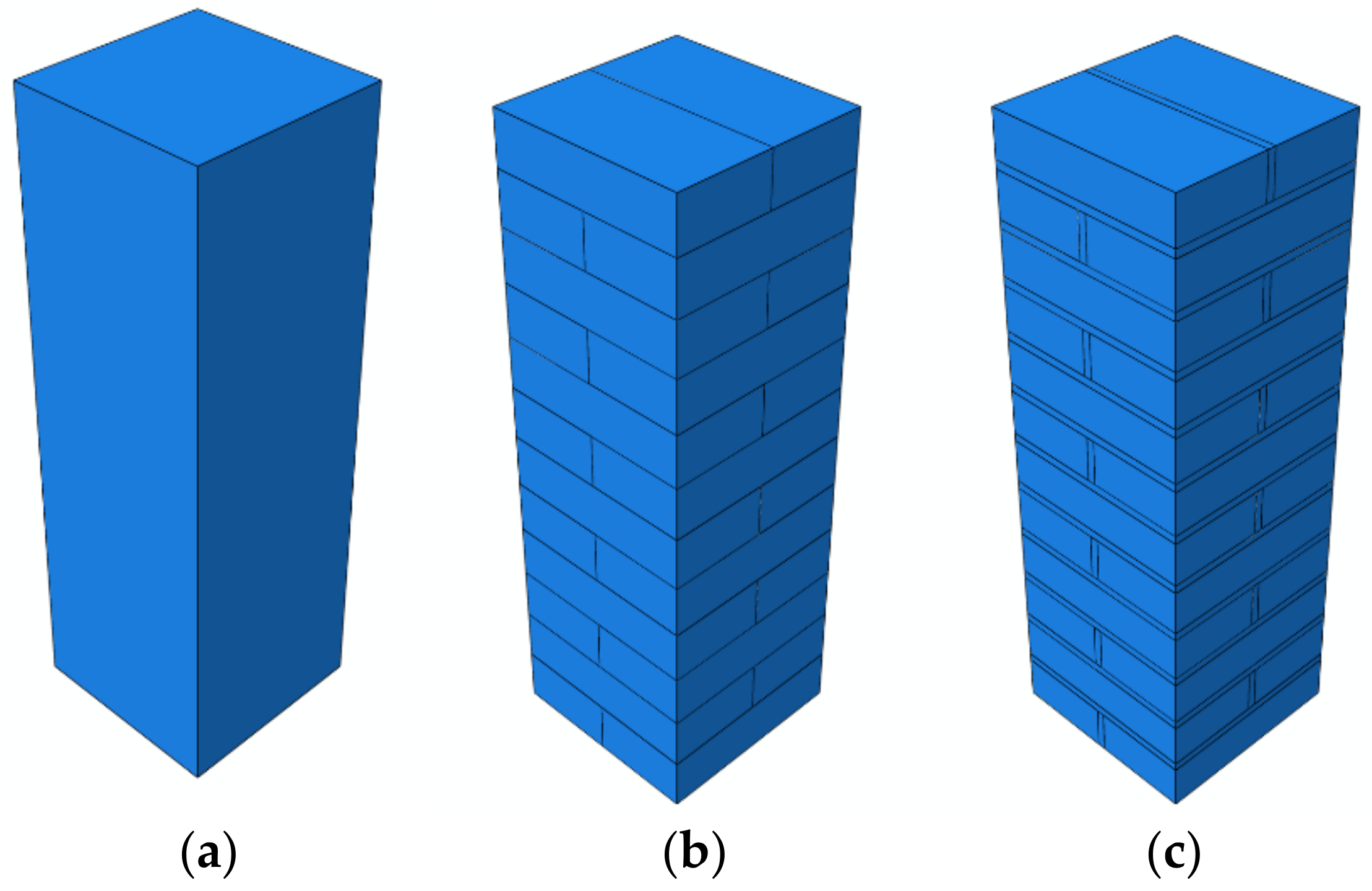
The performance of the numerical model depends on the experimental description of the heterogenous behavior of the masonry structure through the adequate constitutive laws. The type of experimental method used for evaluating the material properties and the boundary conditions are of critical importance for the numerical model and results. However, particular attention should also be given to the geometrical aspects of the masonry structure: unit dimensions, type and quality of mortar joint, and unit surface conditions. The variety of clay brick units and mortar types and typology methods of construction do not allow development of unified constitutive laws. In fact, several codes and standards prioritize experimental characterizations of material properties for design and numerical simulations [74,75]. The set of mechanical properties used for the masonry numerical model depends both on the accurate description (elastic and inelastic) of material and on the adopted modeling approach. Generally, the elastic range can be defined through the modulus of elasticity and the compressive strength. When a description of cracking is necessary, the nonlinearity effects are necessary through additional mechanical properties such as shear strength, tensile strength, and fracture energies. The extent of knowledge required on material properties depends on the modeling strategy, where in technical literature [76] there are three different approaches aimed at the modeling of a masonry column: (i) macro-modeling, (ii) micro-modeling, and (iii) simplified micro-modeling. In Figure 1, the schematic models used for a small-scale column are reported.
2.1.1. Macro-Modeling (MA-Approach)
This is the simplest of the three approaches, where the single brick and the mortar joint merge into a unique element. This approach does not take into account the interaction between the two constituents of the column. In the literature, there exists two different strategies where the internal structure of masonry cannot be described explicitly and the damage within the masonry is evaluated through a continuous medium. The first strategy most widely used is considered as a homogenous and anisotropic material using plasticity or another macro-scale constitutive relationship. The main advantage consists of the reduced computational burden (time-consuming). Moreover, this method is the most used by researchers; in fact, in the literature there are different studies that take into account different strategies based on this technique. In [49,77,78,79,80,81], the research developed a shear wall or masonry column such as a continuous element where the mortar unit of clay brick was described through an average function of the mechanical properties of the single parts. The second strategy is based on the reduction in the elasticity modulus by increasing the load in the model, which represents the propagation of cracks in the elements. This strategy is generally used in reinforced concrete.
2.1.2. Micro-Modeling (MI-Approach)
This approach is more realistic, and it takes into account the behavior of the single constituents of the column such as continuous and discontinuous elements. In fact, it is also known as the heterogeneous approach, while in terms of time it is uneconomic and inefficient because of the many parameters and various interactions between the individual parts. It introduces two important steps to create a numerical model, which are the local and global steps of the unreinforced masonry. The local view refers to the single details in terms of geometrical and mechanical characteristics, respectively, while the global view refers to the definition of contact surface (plane) and interaction (Mohr–Coulomb [82,83] law) among all the parts. Therefore, this approach is not applicable if applied on a realistic scale of masonry structures. Moreover, to avoid this drawback, in the literature there are two strategies. Both strategies focus their attention on how to represent and how to model the mortar joint. The first strategy considers the masonry made only of bricks while modeling the vertical and horizontal mortar joints as an interaction surface [84,85] with a zero thickness. The merging of the clay brick and the mortar joint (as interaction surface) is called the unit to represent the continuum elements. Important research conducted in [84] followed this approach, where the mortar joints (vertical and horizontal) are modeled through the elastic–plastic behavior of the interface. The obtained numerical curves fit the experimental results satisfactorily. The second approach consists of representing the mortar joint with its real geometric thickness [85], thus modeling the entire masonry 3D structure, including both the brick and the mortar joints. In particular, the modeling of mortar joints requires particular attention, such as isolating a part of the structure for particular boundary conditions [85] or inhibiting any interaction with the external reinforcement [33]. Furthermore, in terms of mortar strength, there is a reduction and the introduction of penalties at the interaction surface in terms of tangential behavior. In addition, this approach with respect to the first one allows the occurrence of cracks in the mortar joints and in the brick unit.
2.1.3. Simplified Micro-Modeling (SIMI-Approach)
This approach is an intermediate one with respect to macro- and micro-modeling, which is generally used in real-scale structures. In the literature, there are two strategies for using this modeling. The first strategy consists of those mortar joints that are clamped into the unit/mortar interface as a discontinuous element. Expanded units, up to half of the mortar thickness in vertical and horizontal directions, were simulated by continuum elements as reported in [13,86,87,88]. In this approach, the mortar joints are considered as the weakest elements and modeled by an elastic–plastic interface behavior. The obtained results showed that the strategy was able to reproduce the experimental response and evaluate the cracks inside the expand unit. The second strategy, called the homogenization approach in the literature, is reported in [56,89]. It is made up of periodic units. Through the periodic units, it is possible to model heterogeneous masonry structures, reducing the number of material parameters and by avoiding independent modeling of all mortar joints. The use of these strategies permits the modeling of masonry structures, reducing the computational burden and, at the same time, the material parameters in input. The obtained results showed that the strategy was able to reproduce the experimental response and evaluate the cracks.
2.2. Constitutive Laws of: Unreinforced Masonry (URM), Clay Brick and Mortar Joints
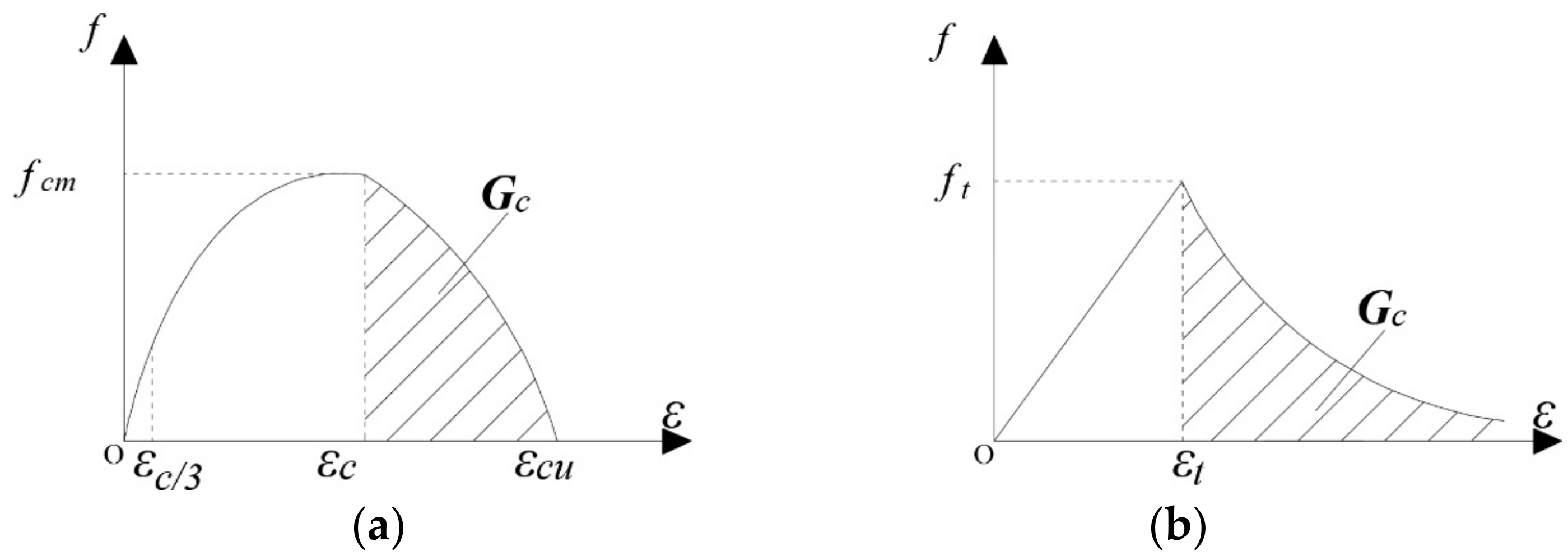
A largely adopted constitutive law is based on Feenstra [90]. It considers a three-branch behavior in compression. For it, the macro and simplified micro approaches were used. The geometrical and the mechanical parameters that govern the model are compressive strength (fcm), elastic modulus (Ecm), fracture energy (Gcm), and mesh size (h).
The ultimate strain depends on two parameters; fracture energy (Gcm) and the characteristic element length (h). Fracture energy (Gcm) was computed as being equal to the area under the softening third branch (Equation (1)), while the h is evaluated as the cubic root of the masonry column volume.
Other researchers used a modified constitutive law based on that of reinforced concrete [91], described by nonlinear equations. The simplicity of this last approach is due to the parameters involved, i.e., the stress (fcm) and the relative strain (εc) at peak. The constitutive tensile law was modeled according to the following branches. The first branch is linear elastic until the peak tensile stress (fct), while the second branch is expressed by:
where εt is the crack strain and εtu is the ultimate crack strain. The softening branch also depends on the fracture energy (Gfm) and the characteristic element length. The Gfm is evaluated according to:
while h is evaluated according to Equation (6). Therefore, the ultimate crack strain is:
However, the post-peak branch is exponential and, to avoid snap-back phenomena, the parameter h is evaluated according to the expression:
where Etm is the initial tangent Young’s modulus. The constitutive law in tension and in compression were reported in Figure 2, which is possible to use by the internal functions of the commercial software adopted [92], called Elastic (E) and Concrete Damage Plasticity (CDP).
The elastic branch of the constitutive law (compression and tension) was modeled in E by parameters such as density (ρ), both elastic modulus in compression and in tension (Ecm and Ect), the Poisson ratio (ν), and the maximum stress (f), which were kept constant during the analysis. The nonlinear branches, in terms of two main failure mechanisms, which are compressive crushing and tensile cracking, were modeled through the CDP. The evolution of the yield surface is controlled by two hardening variables called equivalent plastic strains in compression and in tension. Consequently, in the CDP model, one must necessarily describe the behavior in uniaxial terms outside the elastic branch. Moreover, the CDP entails the nonlinear branch through the following parameters, namely, the yield stress damage parameter and the relative strain inelastic and cracking for the masonry compression and tension damage, respectively. The CDP function, as understood by its name, is a concrete material function, but by means of the following parameters it was possible to adopt this function for the masonry column as reported in [77,93,94,95,96] and for other quasi-brittle materials:
- Dilation angle (DA): 30° angle measured in the meridional plane between the failure surface and the hydrostatic axis;
- Plastic potential eccentricity (PPE): 0.1 due to a non-associated potential plastic flow and it is a length’s segment between the vertex of the hyperbola and the asymptotes with respect to the center of the hyperbola;
- Ratio between the initial biaxial and yield compressive stress: 1.16;
- Viscosity parameter (VP): 0.0 visco-plastic regularization.
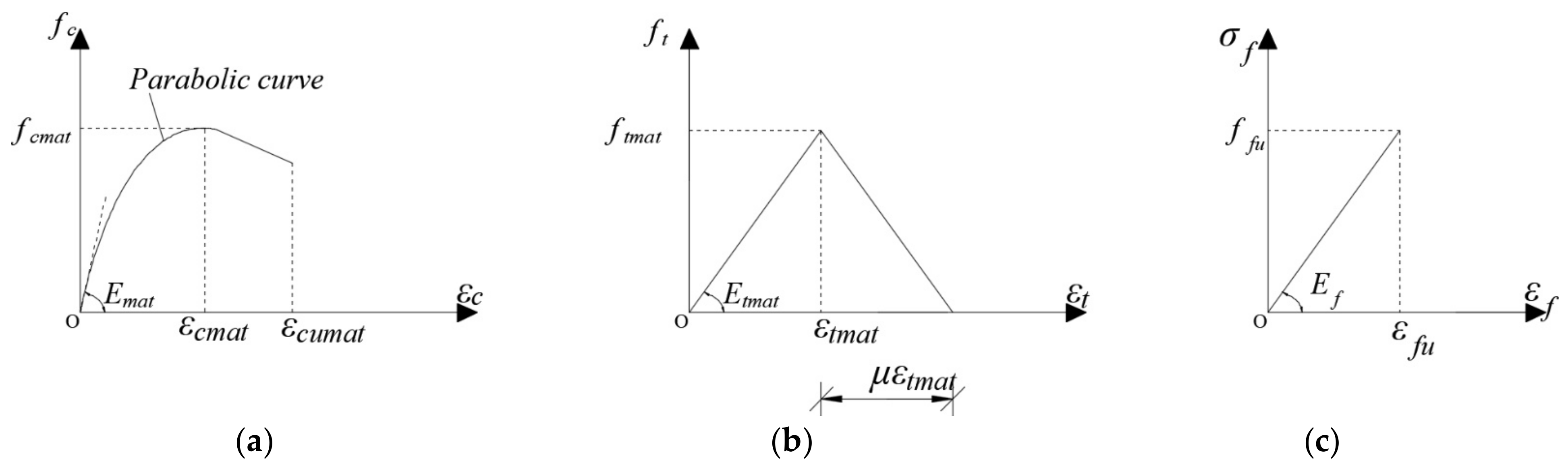
In the SIMI approach, the periodic unit was modeled in compression using Equations (1)–(6). Through the micro approach, it was possible to independently describe both the single clay brick and the mortar joints. In particular, the clay brick was modeled by linear elasticity until failure by function E through the mechanical parameters (fbrick and Ebrick), generally evaluated by [95,96], while the mortar joints were modeled in both compressive and tensile behavior, through function CDP. The compressive constitutive law was modeled with a nonlinear model suggested in [77,92,93,97,98,99], while the equations are reported by the following:
where fcmat is the peak compression stress and the relative strain. The strain is evaluated by Equation (12) and the Young’s modulus (Ecmat):
In addition, the tensile constitutive law was modeled with a bilinear model [77,92,93,97,98,99] with a µ factor equal to 25.
In both micro- and simplified micro-modeling strategies, an important step is the definition of contact surfaces and the type of interaction. The contact surfaces between expansion cells by a standard contact including surface-to-surface and self-contact was used to avoid penetration among them. The surfaces were assumed to be zero thickness; therefore, hard contact for normal behavior of contact was assigned. Hard contact refers to an interaction without any softening to avoid no penetration of the surfaces, which can occur in the model. Another mechanical characteristic was assigned in terms of tangential behavior, called the friction coefficient. Generally, the most common friction coefficient of concrete/masonry, which is set equal to 0.67, is reported in [100]. Meanwhile, in the micro-modeling, all nodes are degree-of-freedom and the bond slip is not considered between brick and mortar. In other words, the perfect bond between the vertical and horizontal mortar joints and between single clay bricks and the mortar joints were considered. This strategy, because of the not easy estimation of bond parameters and the related slip law between the single clay brick and the mortar joints [83], is hard to apply. In all of the three approaches, it is possible to introduce the cracking phenomenon to simulate the experimental behavior of the masonry or concrete structures being tested. This phenomenon is introduced through the nonlinear behavior of the material in compression and in tension, as reported in these studies [77,78,80,94]. The results furnished are in good agreement in the comparison between the numerical model and the experimental one. Moreover, the authors emphasize that the efficiency is related to the accurate definition of the equations that describe the behavior of the unreinforced column and the nonlinear solution strategy.
2.3. FRCM–SRG (Macro and Micro-Approach) and Interface Modeling
The numerical simulation of the FRCM or SRG system for the confinement of masonry columns is poorly investigated in the literature. All the available studies [58,59,60,61,62,63,64,65,66,67,68,69,70,71,72,73,77] carried out by the authors are devoted, as their main goal, to the investigation of the structural or the debonding problem and to model the strengthened systems on the basis of the experimental results that refer to the specific type of FRCM or SRG systems. A clear distinction within the FRCM systems is crucial for proper selection of the numerical strategies. The acronym FRCM includes all of the several types of fibers, namely metallic and nonmetallic ones, their different behavior should be underlined. All nonmetallic reinforcements are characterized by a negligible stiffness, except under tensile stresses in the fiber’s direction; contrarily, the metallic reinforcement, known also as SRG when combined with the mortar matrix, presents a significant stiffness under a different stress state. In the case of confinement, this specific feature often involves a failure by the opening of the jacket after the matrix damage, instead of fibers breaking [68,77]. For the above reason, the two kinds of composites (metallic and nonmetallic) are herein modeled with different strategies. The presence of the metallic reinforcements provides evidence of only one failure type that was possible to observe in the confinement action, independent of the matrix (cement or lime-based) used [67,68]. Consequently, the matrix was not physically modeled, but the low influences were considered in the mechanical values of system characterization by tensile tests on SRG specimens made up of fiber and matrix [68]. The above-stated and the effect of the matrix in the FRCM system, based on the experimental observation, has a crucial role for the initial tensile stiffness of the composite, while the fabric mainly affects the strength and the post-cracking stiffness. In the relatively few works present in the technical literature [77,93,101,102] the matrix was excluded from the numerical model. The performance and effects of the matrix were considered in this model by assessing the mortar cracking. Generally, the ductility is related to the damage evolution depending on both the matrix and the fabric and on their interactions. In fact, the nonlinear models for the matrix and the fabric and matrix modeled separately were introduced. The behavior of external reinforcement was described by two approaches: macro approach (MA) and micro approach (MI). The first approach (MA) was used for the SRG system, where the strengthened system is modeled without distinguishing the matrix (lime- or cement-based) and the fabric by an element shell. This approach is made possible by similar values between the mechanical value of the dry fibers such as steel fibers (with different steel density) and the mechanical values obtained by tensile tests on the SRG specimen (steel fibers and matrix), while the second approach (MI) was used for the FRCM system, where the external reinforced (matrix) was modeled with real thickness (tfm) and the fabric was modeled with the equivalent thickness (tf) for both reinforcement systems. The compressive constitutive law of the matrix was modeled with a nonlinear model (see Figure 3), while the tensile constitutive law was modeled with a bilinear model. The equations used are (11)–(13). The behavior in compression and in tensile was described by the CDP function. A similar modeling technique was used in [75,76,77,78,79,80,81,82,83,84,85,86,87,88,89,90,91], where the external FRCM reinforcement was used to strengthen the unreinforced masonry columns. In both approaches for the two external reinforcement systems, the fabric was linear-elastic-until-failure modeled (see Figure 3) and was described by the internal function E.
Moreover, even if the adhesion of the composite with the masonry substrate is generally not relevant in the case of confinement, as demonstrated for the case of FRP [103], a perfect bond was considered in the proposed numerical simulations to make the computation easier and more robust. The same assumption was also imposed for the bond between the matrix and the fabric interaction for the FRCM system. On the basis of the failure mode [58,59,60,61,62,63,64,65,66,67,68,69,70,71,72,73], in particular in the overlap zone, the presence of a greater quantity of fibers was considered through the equivalent thickness parameter (tf and tmat), modifying it appropriately.
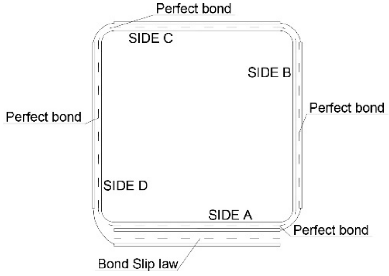
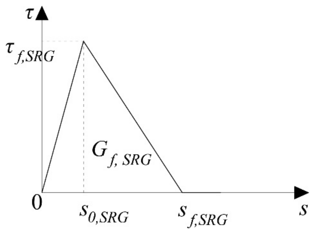
The interaction between the steel fabric and the overlap layer was used as an interface cohesive surface and a different interaction between the masonry substrate and the external reinforcement was considered (see Figure 4). The bond slip law adopted is reported in [104]; in particular, it is a bilinear model. The bond slip law was evaluated by statistical studies and a meso-scale finite element model on a large database on the single-lap direct shear test. The latter one was used to evaluate the initial stiffness of the bond slip curve. This bilinear model is illustrated in Figure 5.
To evaluate parameter k0, many experimental results are needed. This is due to the limited available test results relative to the considered confining systems. Consequently, the value of k0,SRG was assumed unchanging with respect to that reported in [104]. The parameter Gf,SRG was calculated as:
Finally, the parameters s0,SRG and sf, SRG are evaluated by the following equations:
and they depend on the geometric parameter βw, the fractures energy (Gf,SRG), and tensile strength of the mortar (ftmat). The bond slip law adopted depends on the three failure modes that are due to the opening and sliding associated with the normal and shear stress, respectively. The initialization and evaluation of the damage were evaluated by the quadratic function reported in a previous numerical work on the columns strengthened with an SRG system [77,92].
2.4. Geometry, Boundary Conditions, and Solution Technique
The all-masonry columns were modeled in three dimensions (3D) through the three types of modeling strategies described in Section 2. The element used to model the masonry column, single clay brick, mortar joints, and external matrix of FRCM system is the linear tetrahedral four node C3D4 element with constant stress. The FE element used in the MA for the SRG system and fibers of the FRCM system is a two-dimensional shell element called S4R. This element is used to model mono-dimensional structures with small thickness. The equivalent thickness of the fibers (tf) adopted for the S4R element is equal to the values of the fabric mesh considered, while the matrix thickness (tmat) is equal to the matrix layer adopted in the tests. Moreover, the masonry column equipped with externally reinforced corners was rounded to avoid stress concentration. All numerical tests in displacement control were conducted through the enforcement of a displacement -λu along the y-axis. The displacement on the entire surface at the top column was applied, while all nodes on the surface of the column bottom (translations and rotations) were blocked. To solve the nonlinear equations associated to the numerical problem focused on in this work, a dynamic approach was used. Generally, this approach is not used to solve a quasi-static problem because of the parameters involved. The first users of this technique were Chen et al. [105]; they suggested paying particular attention to two parameters, providing their values to obtain only the static solution. The first parameter is the variable mass scaling and the value used is equal to 0.00005. The role of this parameter is to scale the mass of all (or single macro-element) the elements at the beginning of a step and periodically during the displacement phase. The second parameter is the ratio between the kinetic and total energy of the model. The value of this ratio is less than 5% during the entire analysis, except at the first displacement increment.
3. Inventory of Experimental Data and Results
3.1. Unreinforced Masonry (URM)
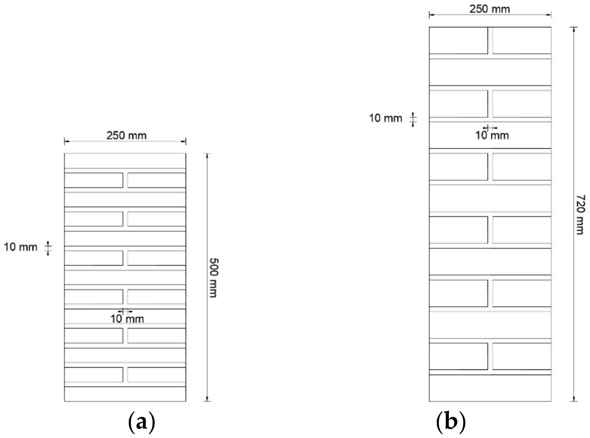
The unreinforced masonry considered in this numerical work was reported in [65,68]; in particular, both experimental campaigns reported that all masonry columns had a square-type cross-section of 250 × 250 mm with a horizontal and vertical thickness of mortar joints of 10 mm. The current columns have different heights equal to 500 and 720 mm, respectively. Finally, two and three unreinforced columns in [65,68] were used as reference columns, respectively.
Table 1 and Figure 6 show all mechanical and geometrical parameters regarding the unreinforced masonry columns investigated in [65,68].
The columns were tested under axial compression, and the typical failure observed was masonry crashing (brittle failure) through a vertical crack in the mortar joints that was then propagated at the single clay brick units. In Table 2, a compressive strength fcm (peak stress) and the elastic modulus in compression Ecm were reported. The value of Ect (elastic modulus in tension) was set equal to compression.
To perform the analyses of the available case studies, it was necessary to assume values for the missing parameters. The available literature overviewed in the present work along with the guidelines [106] offers an adequate amount of information upon which to base these assumptions. The average values of Poisson’s ratio υ was equal to 0.15, 0.20, and 0.3 for the masonry, mortar joint, and clay brick, respectively; similar values were adopted in [78,81,85,94,107,108,109]. The values used for the density ρ was suggested by the standard [106] and it was equal to 18 (kN/m3). The elastic modulus for mortar joints was calculated according to Eurocode 2 [110]. Finally, parameter fct was set equal to 1/3 fcm.
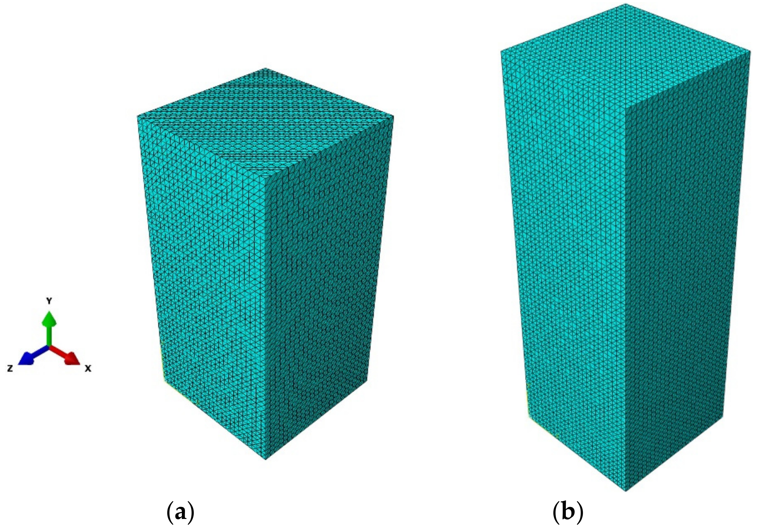
The parameter is that the softening branches of the constitutive laws of materials depend on fracture energies (Gcm and Gfm) and these were calculated by the equations reported in [100]. The values adopted are 0.784 and 0.25, respectively, for the experimental campaign reported in [65]. While for the [68], they were equal to 0.760 and 0.025, respectively. Finally, for both [65,68], the parameter h was set equal to 10, while in Figure 7 the finite-element resolution is shown.
3.2. FRCM and SRG System
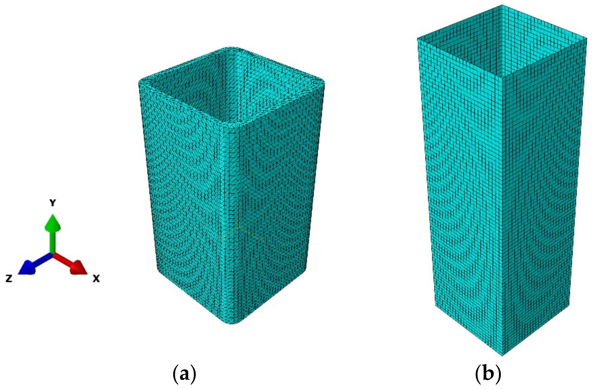
In [65], nine columns were divided into three groups (three columns for each group); they were reinforced with the G-FRCM system using glass fiber combined with a different strengthening mortar. As described in the section, the FRCM external reinforcement was modeled through the MI approach. The matrix was modeled in 3D with its real thickness, while the fiber was modeled in 2D through its equivalent thickness. Specifically, the mortars presented a difference in terms of compression strength (fcmat), and in Table 3 the flexural, compressive strength and the elastic modulus are reported (Emat). The thickness (tmat) adopted per all types of mortar is equal to 5 mm, while the density (ρ) and Poisson’s ratio υ were assumed to be 20 (kN/m3) and 0.15, respectively. In Figure 8, the finite-element resolution for external reinforcement is shown.
All columns were reinforced with a single layer of continuous reinforcement over the entire height of the column, while the length of the overlap was equal to the width of the column. The mechanical properties of glass fibers in terms of tensile strength (ffu) and elastic modulus (Ef) were equal to 742.40 (CoV 9%) and 37,120 (11%) MPa, respectively. Meanwhile, the equivalent thickness (tf) was equal to 0.046 mm. In addition, round corners equal to 30 mm were in the four column corners to avoid stress concentration.
The typical failure observed was the brittle failure type, while a knife effect was observed for the reinforced ones, i.e., opening of a large vertical crack in the corner zone (overlap zone). In [68], the masonry columns were reinforced by an SRG system; in particular, three groups of four reinforced columns were considered. The reinforced system consisted of two types of inorganic matrices (hydraulic lime mortar and cementitious mortar matrix) with compressive strengths and different steel density.
The first approach used with the SRG system is MA without distinguishing the mortar and the steel fabric, and it was modeled in 2D. The equivalent thickness value used depends on the steel fibers’ density (Table 4) and the constitutive law was linear elastic until failure. The mechanical parameters adopted in terms of tensile strength (fSRG), ultimate strain (εSRG), and cracked modulus (ESRG) were suggested by the manufacturer [111], and they were obtained by tensile tests on the SRG specimen. In addition, the density used is equal to 7.8 g/cm3. The mechanical parameters of the bilinear model are summarized in Table 5.
The typical failure observed, independent of the types of steel density and inorganic matrix used, was located at the overlap zone with the opening of the reinforcement jacket. It should be noted that by increasing the steel density it was possible to observe a decrease in terms of peak axial strength. Table 6 shows the peak axial strength values for each type of column analyzed in [68].
3.3. Experimental versus Numerical Results
3.3.1. Unreinforced Columns
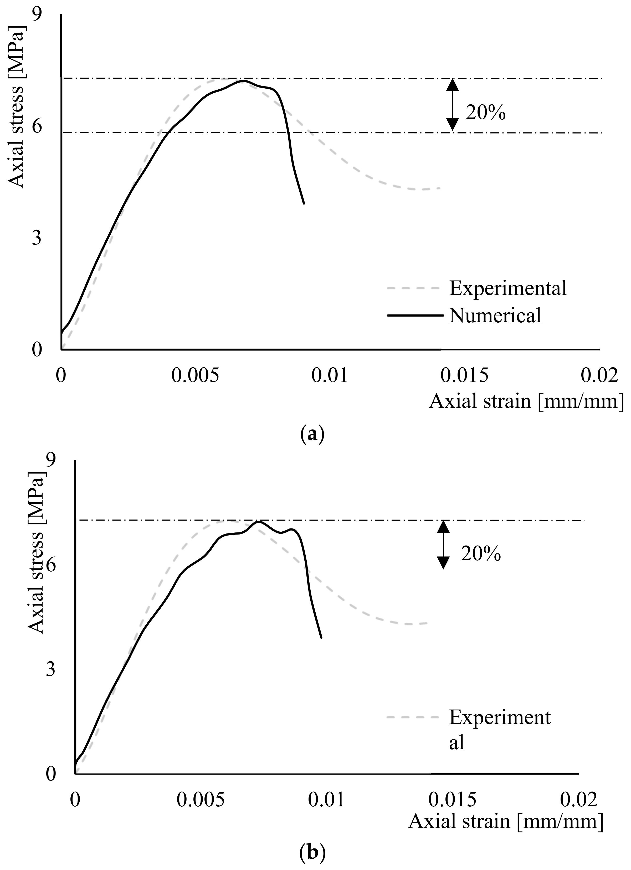
Figure 9 shows the comparison between the stress–axial-strain curves obtained from experimental tests and the numerical results obtained by the MA for the experimental campaign reported in [65,68]. The numerical branch before the peak stress is in good agreement with the experimental curves, while the softening branch presents higher scatter. In terms of peak axial stress, the numerical curves present an error between 2 and 3%. Furthermore, in terms of peak axial stress, the error of the curves shown in Figure 9 was evaluated by means of Equation (19) and summarized in Table 7.
The numerical model curve is affected by the type of approach used; in particular, the experimental curves have a more rapid descending post-peak branch until final collapse.
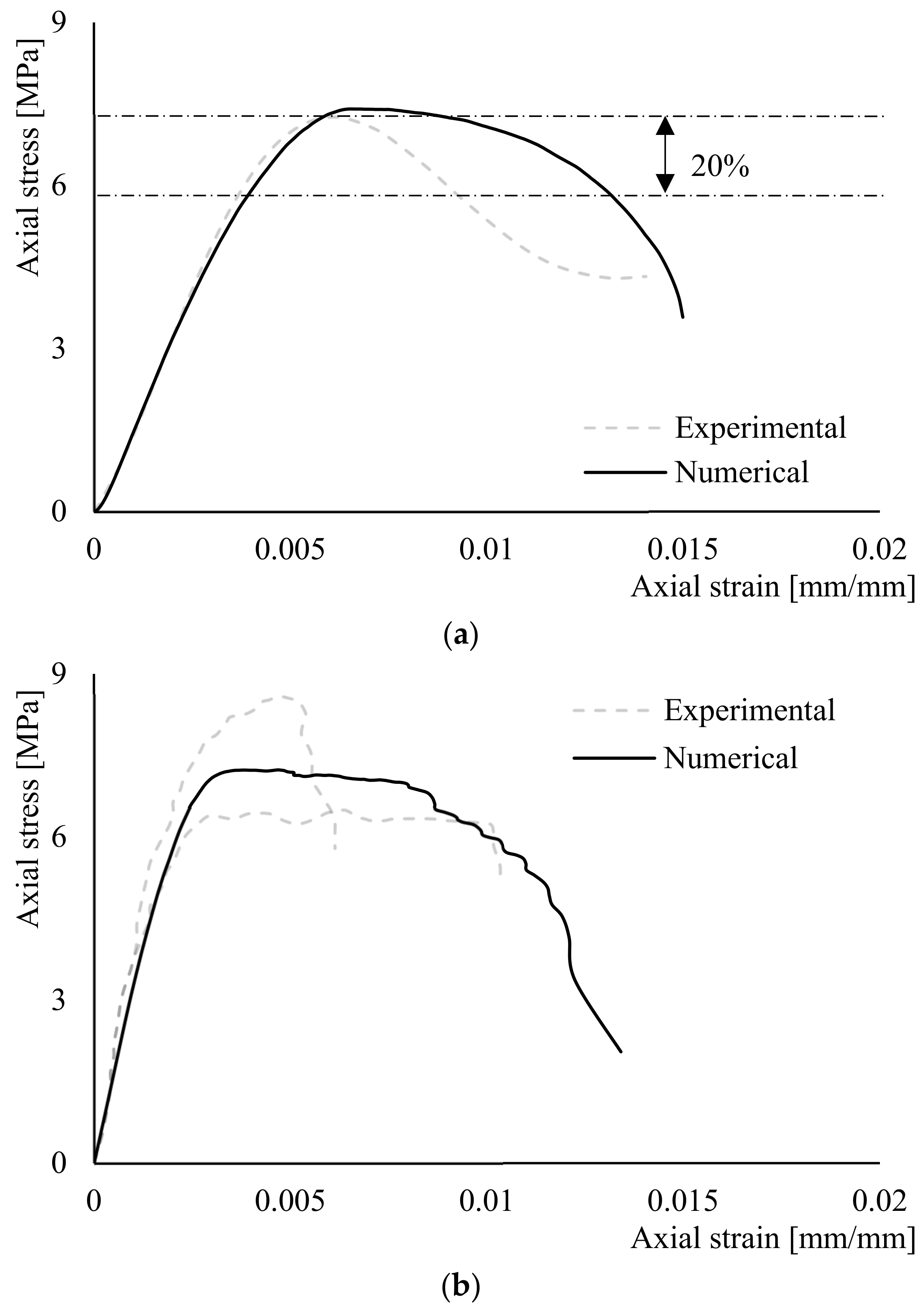
Figure 10 shows the comparisons between the experimental curve reported in [65] and the curves obtained from the numerical models by using the MI and SIMI approaches. In terms of peak stress, lower values are reached compared with the experimental and with higher values of axial deformation in correspondence to the peak stress. However, in the first branch, the numerical curve differs from the experimental one and exhibits nonlinear behavior before reaching the peak stress. In addition, it is possible to observe drops near the peak stress because of the type of interaction adopted. The differences in drops are more pronounced in the SI approach. Finally, for the assumptions present in the interaction between bricks and mortar joints and between the mortar joints themselves, the compressive and tensile strength of the vertical mortar joints was reduced by 50% as suggested in [81] to not harden the numerical model and cause failure in the vertical mortar joints. The softening branch is in good accordance until the reduction of 20% in the peak stress. In terms of peak axial stress, the numerical curves present an error of less than 1% for both the approaches.
3.3.2. Wrapped Columns
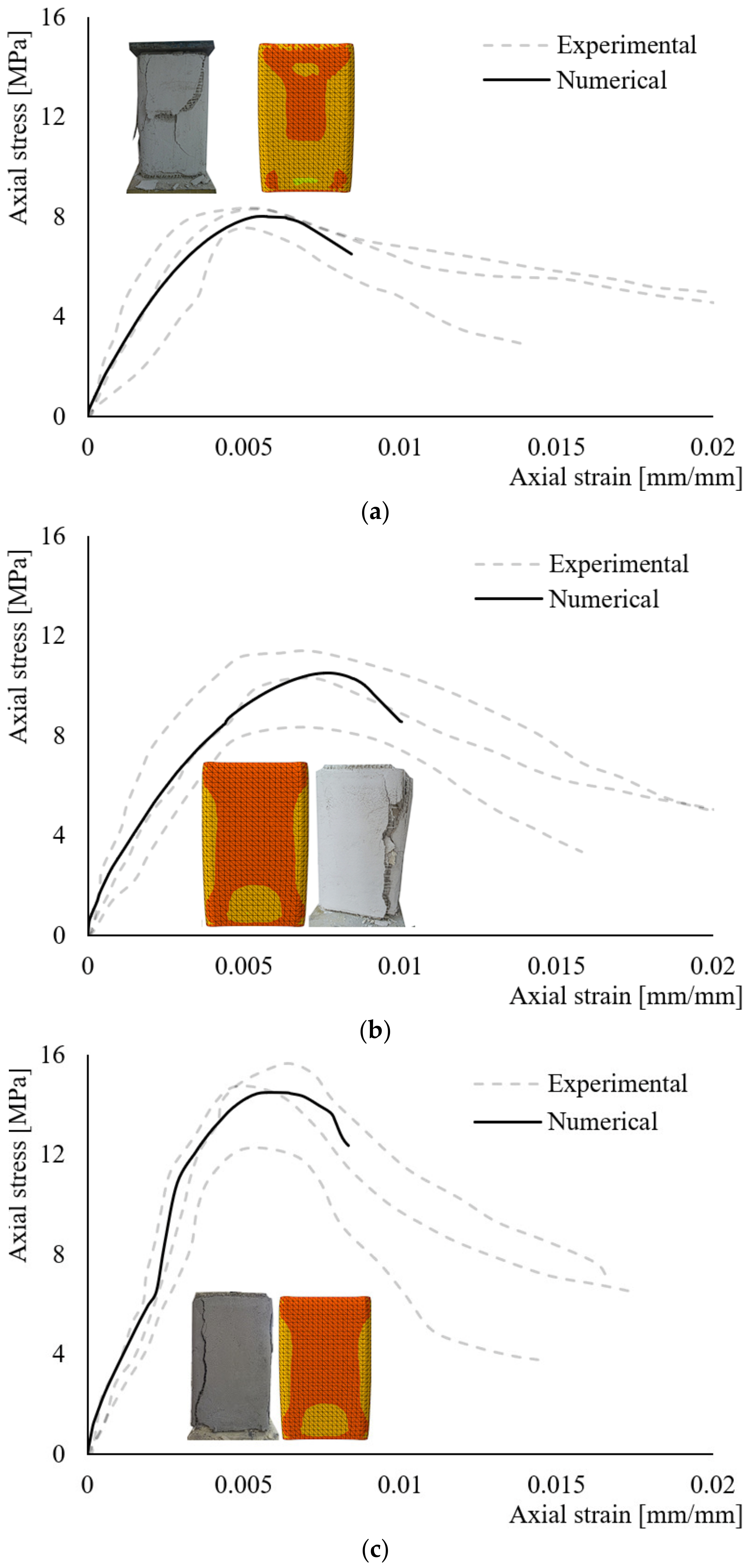
The external reinforcement called FRCM, which the columns reported in [65], were reinforced and modeled in 3D. In particular, the glass fibers were described by a 2D model, while the matrix was by a 3D model. In Figure 11, the comparison between the experimental curves and the numerical curves is shown. It should be noted that the strategy adopted to emphasize the matrix effect of the numerical curve is in good agreement with the experimental ones. In addition, the numerical curves showed good accordance in terms of both peak axial stress and branches until the peak axial stress. The post-peak branch was reduced because of the models used to describe the behavior of the external reinforcement, particularly for the excessive distortion of the FE elements used.
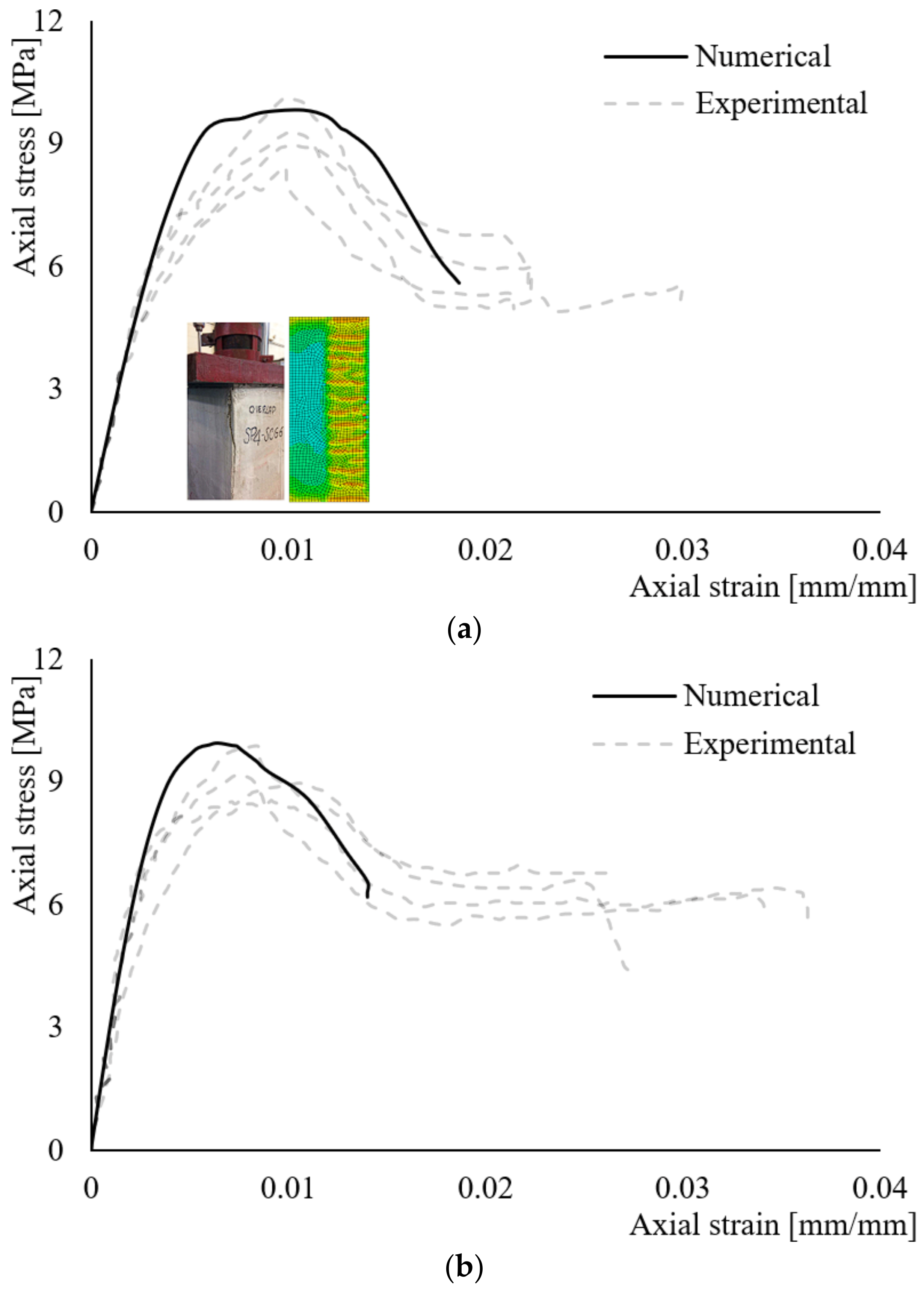
In Table 8, the error evaluated by Equation (19) is summarized. In Figure 11, the crack pattern at failure is also reported and is compared to that observed experimentally. The modeling strategy adopted is in good accordance with the experimental in terms of the crack pattern. The error evaluated through Equation (19) is between 1 and 4%. The approach used has a drawback that is due to the excess computational burden. In addition, the matrix effect may be observed, especially for the matrix named FRCM_M23. The columns reinforced with the SRG system [68] were modeled in 2D using the MA approach without distinguishing the matrix and steel fiber. Figure 12 shows the comparison between the experimental curves and that obtained from the numerical model varying the type of matrix and density of steel fibers.
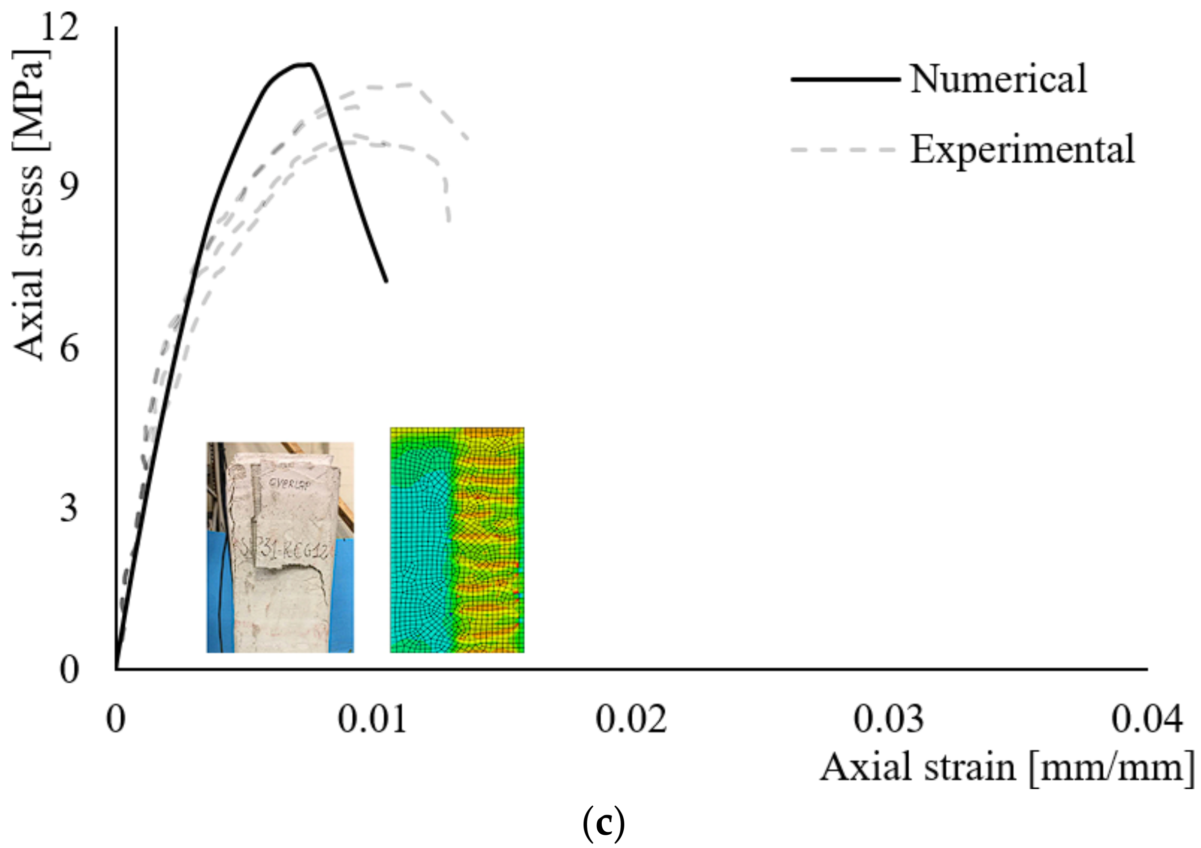
The error is between 5 and 8%. The values are slightly higher than those obtained with the approach used for the FRCM system. This approach has the advantage of a lower computational burden and, consequently, may be used for structures of greater geometric dimensions. The crack pattern at failure is also reported in Figure 12. It is possible to note the detachment along the overlap zone along the entire height of the column. While the one observed experimentally is sometimes localized and does not develop along the entire height, this type has also been noted in [77,92]. Localized detachment is caused by the arrangement of the steel sheet during the casting phase of the steel fibers. The steel fiber sheet is commercialized in 30 cm wide rolls; therefore, multiple sheets of 30 cm wide steel fiber are placed side by side to cover the full height of the column and the several steel cords are joined together by the matrix alone. In Table 8, the errors are summarized.
4. Conclusions
The numerical procedure found, which was based on the finite element, was developed in this paper. Parameters of the numerical model were calibrated on the available experimental results present in the literature. The effectiveness of the model was evaluated by a comparison of test results conducted on clay brick masonry columns confined with FRCM (glass-FRCM) and SRG (with different types of matrix and steel density) systems. Based on the obtained results, the following conclusions can be drawn:
- The different numerical strategies adopted furnish accurate outcomes in terms of axial strength for unconfined masonry columns;
- The proposed strategy adopted to describe the external reinforcement FRCM/SRG by the MA and MI approaches in terms of axial stress and crack pattern are similar;
- For glass-FRCM- and SRG-confined columns, numerical predictions in terms of axial stress–axial strain curves are in good agreement with experimental results in the ascending branches of the curves, while they are inaccurate for describing the post-peak;
- The approach used for the FRCM system resulted in errors of less than 4%, but with a considerable increase in computational burden;
- The approach used for the SRG system could possibly obtain an error of between 5 and 8%.
Further experimental analysis is needed to confirm the results obtained in the investigation described and discussed in the paper.
Funding
This research received no external funding.
Data Availability Statement
Not applicable.
Conflicts of Interest
The author declares no conflict of interest.
References
- Dolatshahi, K.M.; Aref, A.J. Multi-directional response of unreinforced masonry walls: Experimental and computational investigations. Earthq. Eng. Struct. Dyn. 2016, 45, 1427–1449. [Google Scholar] [CrossRef]
- Dolatshahi, K.M.; Yekrangnia, M. Out-of-plane strength reduction of unreinforced masonry walls because of in-plane damages. Earthq. Eng. Struct. Dyn. 2015, 44, 2157–2176. [Google Scholar] [CrossRef]
- Dolatshahi, K.M.; Nikoukalam, M.T.; Beyer, K. Numerical study on factors that influence the in-plane drift capacity of unreinforced masonry walls. Earthq. Eng. Struct. Dyn. 2018, 47, 1440–1459. [Google Scholar] [CrossRef]
- Wilding, B.V.; Dolatshahi, K.M.; Beyer, K. Influence of load history on the force displacement response of in-plane loaded unreinforced masonry walls. Eng. Struct. 2017, 152, 671–682. [Google Scholar] [CrossRef]
- Smoljanović, H.; Živaljić, N.; Nikolić, Ž. A combined finite-discrete element analysis of dry stone masonry structures. Eng. Struct. 2013, 52, 89–100. [Google Scholar] [CrossRef]
- Smoljanović, H.; Živaljić, N.; Nikolić, Ž.; Munjiza, A. Numerical analysis of 3D drystone masonry structures by combined finite-discrete element method. Int. J. Solids Struct. 2018, 136, 150–167. [Google Scholar] [CrossRef]
- Petracca, M.; Pelá, L.; Rossi, R.; Zaghi, S.; Camata, G.; Spacone, E. Micro-scale continuous and discrete numerical models for nonlinear analysis of masonry shear walls. Constr. Build. Mater. 2017, 149, 296–314. [Google Scholar] [CrossRef] [Green Version]
- Addessi, D.; Sacco, E. Nonlinear analysis of masonry panels using a kinematic enriched plane state formulation. Int. J. Solids Struct. 2016, 90, 194–214. [Google Scholar] [CrossRef]
- Serpieri, R.; Albarella, M.; Sacco, E. A 3D microstructured cohesivefrictional interface model and its rational calibration for the analysis of masonry panels. Int. J. Solids Struct. 2017, 122, 110–127. [Google Scholar] [CrossRef]
- Orduña, A.; Lourenço, P.B. Three-dimensional limit analysis of rigid blocks assemblages. Part I: Torsion failure on frictional interfaces and limit analysis formulation. Int. J. Solids Struct. 2005, 42, 5140–5160. [Google Scholar] [CrossRef]
- Orduña, A.; Lourenço, P.B. Three-dimensional limit analysis of rigid blocks assemblages. Part II: Load-path following solution procedure and validation. Int. J. Solids Struct. 2005, 42, 5161–5180. [Google Scholar] [CrossRef] [Green Version]
- Portioli, F.; Casapulla, C.; Gilbert, M.; Cascini, L. Limit analysis of 3D masonry block structures with non-associative frictional joints using cone programming. Comput. Struct. 2014, 143, 108–121. [Google Scholar] [CrossRef]
- Milani, G. 3d upper bound limit analysis of multi-leaf masonry walls. Int. J. Mech. Sci. 2008, 50, 817–836. [Google Scholar] [CrossRef]
- Abdulla, K.F.; Cunningham, L.S.; Gillie, M. Simulating masonry wall behaviour using a simplified micro-model approach. Eng. Struct. 2017, 151, 349–365. [Google Scholar] [CrossRef]
- Zhai, C.; Wang, X.; Kong, J.; Li, S.; Xie, L. Numerical simulation of masonry-infilled rc frames using xfem. J. Struct. Eng. 2017, 143, 04017144. [Google Scholar] [CrossRef]
- Roca, P.; Cervera, M.; Gariup, G.; Pela, L. Structural analysis of masonry historical constructions, classical and advanced approaches. Arch. Comput. Methods Eng. 2010, 17, 299–325. [Google Scholar] [CrossRef] [Green Version]
- Minga, E.; Macorini, L.; Izzuddin, B.A. A 3D mesoscale damage-plasticity approach for masonry structures under cyclic loading. Meccanica 2018, 53, 1591–1611. [Google Scholar] [CrossRef]
- D’Altri, A.M.; Messali, F.; Rots, J.; Castellazzi, G.; de Miranda, S. A damaging blockbased model for the analysis of the cyclic behaviour of full-scale masonry structures. Eng. Fract. Mech. 2019, 209, 423–448. [Google Scholar] [CrossRef]
- Bruggi, M. Finite element analysis of no-tension structures as a topology optimization problem. Struct. Multidiscipl. Optim. 2014, 50, 957–973. [Google Scholar] [CrossRef] [Green Version]
- Bartoli, G.; Betti, M.; Vignoli, A. A numerical study on seismic risk assessment of historic masonry towers: A case study in San Gimignano. Bull. Earthq. Eng. 2016, 14, 1475–1518. [Google Scholar] [CrossRef]
- Valente, M.; Milani, G. Seismic assessment of historical masonry towers using simplified approaches and standard FEM. Constr. Build. Mater. 2016, 108, 74–104. [Google Scholar] [CrossRef]
- Castellazzi, G.; D’Altri, A.M.; de Miranda, S.; Chiozzi, A.; Tralli, A. Numerical insights on the seismic behavior of a non-isolated historical masonry tower. Bull. Earthq. Eng. 2018, 16, 933–961. [Google Scholar] [CrossRef]
- Betti, M.; Vignoli, A. Numerical assessment of the static and seismic behaviour of the basilica of Santa Maria all’Impruneta (Italy). Constr. Build. Mater. 2011, 25, 4308–4324. [Google Scholar] [CrossRef]
- Milani, G.; Valente, M. Failure analysis of seven masonry churches severely damaged during the 2012 Emilia-Romagna (Italy) earthquake: Non-linear dynamic analyses vs conventional static approaches. Eng. Fail. Anal. 2015, 54, 13–56. [Google Scholar] [CrossRef]
- Fortunato, G.; Funari, M.F.; Lonetti, P. Survey and seismic vulnerability assessment of the baptistery of San Giovanni in Tumba (Italy). J. Cult. Herit. 2017, 26, 64–78. [Google Scholar] [CrossRef]
- Betti, M.; Galano, L. Seismic analysis of historic masonry buildings: The vicarious palace in Pescia (Italy). Buildings 2012, 2, 63–82. [Google Scholar] [CrossRef]
- Castellazzi, G.; D’Altri, A.M.; de Miranda, S.; Ubertini, F. An innovative numerical modeling strategy for the structural analysis of historical monumental buildings. Eng. Struct. 2017, 132, 229–248. [Google Scholar] [CrossRef]
- Degli Abbati, S.; D’Altri, A.M.; Ottonelli, D.; Castellazzi, G.; Catteri, S.; de Miranda, S. Seismic assessment of interacting structural units in complex historic masonry constructions by nonlinear static analysis. Comput. Struct. 2019, 213, 51–71. [Google Scholar] [CrossRef]
- Pelà, L.; Aprile, A.; Benedetti, A. Seismic assessment of masonry arch bridges. Eng. Struct. 2009, 31, 1777–1788. [Google Scholar] [CrossRef]
- Zampieri, P.; Zanini, M.A.; Modena, C. Simplified seismic assessment of multi-span masonry arch bridges. Bull. Earthq. Eng. 2015, 13, 2629–2646. [Google Scholar] [CrossRef]
- Cecchi, A.; Sab, K. A homogenized reissner-mindlin model for orthotropic periodic plates: Application to brickwork panels. Int. J. Solids Struct. 2007, 44, 6055–6079. [Google Scholar] [CrossRef] [Green Version]
- Mistler, M.; Anthoine, A.; Butenweg, C. In-plane and out-of-plane homogenization of masonry. Comput. Struct. 2007, 85, 1321–1330. [Google Scholar] [CrossRef]
- Taliercio, A. Closed-form expressions for the macroscopic in-plane elastic and creep coefficients of brick masonry. Int. J. Solids Struct. 2014, 51, 2949–2963. [Google Scholar] [CrossRef] [Green Version]
- Cecchi, A.; Milani, G. A kinematic FE limit analysis model for thick english bond masonry walls. Int. J. Solids Struct. 2008, 45, 1302–1331. [Google Scholar] [CrossRef] [Green Version]
- Godio, M.; Stefanou, I.; Sab, K.; Sulem, J.; Sakji, S. A limit analysis approach based on Cosserat continuum for the evaluation of the in-plane strength of discrete media: Application to masonry. Eur. J. Mech. A Solids 2017, 66, 168–192. [Google Scholar] [CrossRef] [Green Version]
- Calderini, C.; Lagomarsino, S. A micromechanical inelastic model for historical masonry. J. Earthq. Eng. 2006, 10, 453–479. [Google Scholar] [CrossRef]
- Marfia, S.; Sacco, E. Multiscale damage contact-friction model for periodic masonry walls. Comput. Methods Appl. Mech. Eng. 2012, 205, 189–203. [Google Scholar] [CrossRef]
- Salerno, G.; de Felice, G. Continuum modeling of periodic brickwork. Int. J. Solids Struct. 2009, 46, 1251–1267. [Google Scholar] [CrossRef]
- De Bellis, M.L.; Addessi, D. A Cosserat based multi-scale model for masonry structures. Int. J. Multisc. Comput. Eng. 2011, 9, 543. [Google Scholar] [CrossRef]
- Greco, F.; Leonetti, L.; Luciano, R.; Blasi, P.N. An adaptive multiscale strategy for the damage analysis of masonry modeled as a composite material. Compos. Struct. 2016, 153, 972–988. [Google Scholar] [CrossRef]
- Reccia, E.; Leonetti, L.; Trovalusci, P.; Cecchi, A. A multi-scale/multi-domain model for the failure analysis of masonry walls: A validation with a combined FEM/DEM approach. Int. J. Multisc. Comput. Eng. 2018, 16, 325–343. [Google Scholar] [CrossRef]
- Lloberas-Valls, O.; Rixen, D.; Simone, A.; Sluys, L. Multiscale domain decomposition analysis of quasi brittle heterogeneous materials. Int. J. Numer. Methods Eng. 2012, 89, 1337–1366. [Google Scholar] [CrossRef]
- Siano, R.; Roca, P.; Camata, G.; Pela‘, L.; Sepe, V.; Spacone, E. Numerical investigation of non-linear equivalent-frame models for regular masonry walls. Eng. Struct. 2018, 173, 512–529. [Google Scholar] [CrossRef]
- Quagliarini, E.; Maracchini, G.; Clementi, F. Uses and limits of the equivalent frame model on existing unreinforced masonry buildings for assessing their seismic risk: A review. J. Build. Eng. 2017, 10, 166–182. [Google Scholar] [CrossRef]
- Roca, P.; Molins, C.; Marì, A.R. Strength capacity of masonry wall structures by the equivalent frame method. J. Struct. Eng. 2005, 131, 1601–1610. [Google Scholar]
- Pasticier, L.; Amadio, C.; Fragiacomo, M. Non-linear seismic analysis and vulnerability evaluation of a masonry building using the sap2000 v. 10 code. Earthq. Eng. Struct. Dyn. 2008, 37, 467–485. [Google Scholar] [CrossRef]
- Belmouden, Y.; Lestuzzi, P. An equivalent frame model for seismic analysis of masonry and reinforced concrete buildings. Constr. Build. Mater. 2009, 23, 40–53. [Google Scholar]
- Raka, E.; Spacone, E.; Sepe, V.; Camata, G. Advanced frame element for seismic analysis of masonry structures: Model formulation and validation. Earthq. Eng. Struct. Dyn. 2015, 44, 2489–2506. [Google Scholar] [CrossRef]
- Chen, S.Y.; Moon, F.; Yi, T. A macro-element for the nonlinear analysis of in-plane unreinforced masonry piers. Eng. Struct. 2008, 30, 2242–2252. [Google Scholar] [CrossRef]
- Caliò, I.; Marletta, M.; Pantò, B. A new discrete element model for the evaluation of the seismic behaviour of unreinforced masonry buildings. Eng. Struct. 2012, 40, 327–338. [Google Scholar] [CrossRef]
- Xu, H.; Gentilini, C.; Yu, Z.; Wu, H.; Zhao, S. A unified model for the seismic analysis of brick masonry structures. Constr. Build. Mater. 2018, 184, 733–751. [Google Scholar] [CrossRef]
- Block, P. Ochsendorrust network analysis: A new methodology for threedimensional equilibrium. J. Int. Assoc. Shell Spat. Struct. 2007, 48, 167–173. [Google Scholar]
- Fantin, M.; Ciblac, T. Extension of thrust network analysis with joints consideration and new equilibrium states. Int. J. Space Struct. 2016, 31, 190–202. [Google Scholar] [CrossRef]
- Fraternali, F. A thrust network approach to the equilibrium problem of unreinforced masonry vaults via polyhedral stress functions. Mech. Res. Commun. 2010, 37, 198–204. [Google Scholar] [CrossRef]
- Fraddosio, A.; Lepore, N.; Piccioni, M.D. Lower bound limit analysis of masonry vaults under general load conditions. In Structural Analysis of Historical Constructions; Springer: Berlin/Heidelberg, Germany, 2019; pp. 1090–1098. [Google Scholar]
- Milani, G. Upper bound sequential linear programming mesh adaptation scheme for collapse analysis of masonry vaults. Adv. Eng. Softw. 2015, 79, 91–110. [Google Scholar] [CrossRef]
- Chiozzi, A.; Milani, G.; Tralli, A. A genetic algorithm NURBS-based new approach for fast kinematic limit analysis of masonry vaults. Comput. Struct. 2017, 182, 187–204. [Google Scholar]
- Mezrea, P.E.; Yilmaz, I.A.; Ispir, M.; Binbir, E.; Bal, I.E.; Ilki, A. External jacketing of unreinforced historical masonry piers with open-grid basalt-reinforced mortar. J. Comp. Constr. 2017, 21, 04016110. [Google Scholar] [CrossRef]
- Fossetti, M.; Minafò, G.; Papia, M. Flexural behaviour of glulam timber beams reinforced with FRP cords. Constr. Build. Mater. 2015, 95, 54–64. [Google Scholar] [CrossRef]
- Santandrea, M.; Quartarone, G.; Carloni, C.; Gu, X. Confinement of masonry columns with steel and basalt FRCM composites. In International Conference on Mechanics of Masonry Structures Strengthened with Composites Materials; MuRiCo6; Trans Tech Publications Ltd.: Bäch, Switzerland, 2017. [Google Scholar]
- Maddaloni, G.; Cascardi, A.; Balsamo, A.; di Ludovico, M.; Micelli, F.; Aiello, M.A.; Prota, A. Confinement of Full-Scale Masonry Columns with FRCM Systems. Key Eng. Mater. 2017, 747, 374–381. [Google Scholar]
- Ombres, L.; Verre, S. Analysis of the Behavior of FRCM Confined Clay Brick Masonry Columns. Fibers 2020, 8, 11. [Google Scholar] [CrossRef] [Green Version]
- Carloni, C.; Mazzotti, C.; Savoia, M.; Subramaniam, K.V. Confinement of Masonry Columns with PBO FRCM Composites. Key Eng. Mater. 2014, 624, 644–651. [Google Scholar] [CrossRef]
- Aiello, M.A.; Cascardi, A.; Ombres, L.; Verre, S. Confinement of masonry columns with the FRCM-system: Theoretical and experimental investigation. Infrastructures 2020, 5, 101. [Google Scholar] [CrossRef]
- Cascardi, A.; Micelli, F.; Aiello, M.A. FRCM-confined masonry columns: Experimental investigation on the effect of the inorganic matrix properties. Constr. Build. Mater. 2018, 186, 811–825. [Google Scholar] [CrossRef]
- Aiello, M.A.; Bencardino, F.; Cascardi, A.; D’Antino, T.; Fagone, M.; Frana, I.; La Mendola, L.; Lignola, G.P.; Mazzotti, C.; Micelli, F.; et al. Masonry columns confined with fabric reinforced cementitious matrix (FRCM) systems: A round robin test. Constr. Build. Mater. 2021, 298, 123816. [Google Scholar]
- Sneed, L.H.; Carloni, C.; Baietti, G.; Fraioli, G. Confinement of Clay Masonry Columns with SRG. Key Eng. Mater. 2017, 747, 350–357. [Google Scholar] [CrossRef]
- Sneed, L.H.; Baietti, G.; Fraioli, G.; Carloni, C. Compressive Behavior of Brick Masonry Columns Confined with Steel-Reinforced Grout Jackets. J. Comp. Constr. 2019, 23, 04019037. [Google Scholar]
- Ombres, L. Confinement Effectiveness in Eccentrically Loaded Masonry Columns Strengthened by Fiber Reinforced Cementitious Matrix (FRCM) Jackets. Key Eng. Mater. 2014, 624, 551–558. [Google Scholar] [CrossRef]
- Theofanis, K.D. Textile reinforced mortar system as a means for confinement of masonry structures. In Proceedings of the 12th International Symposium on Fiber Rein-forced Polymers for Reinforced Concrete Structures (FRPRCS-12), Nanjing, China, 14–16 December 2015. [Google Scholar]
- Incerti, A.; Vasiliu, A.; Ferracuti, B.; Mazzotti, C. Uni-Axial compressive tests on masonry columns confined by FRP and FRCM. In Proceedings of the 12th International Symposium on Fiber Reinforced Polymers for Reinforced Concrete Structures & The 5th Asia-Pacific Conference on Fiber Reinforced Polymers in Structures, Joint Conference, Nanjing, China, 14–16 December 2015. [Google Scholar]
- Valdés, M.; Concu, G.; De Nicolo, B. FRP strengthening of masonry columns: Experimental tests and theoretical analysis. Key Eng. Mater. 2015, 624, 603–610. [Google Scholar] [CrossRef]
- Witzany, J.; Zigler, R. Stress state analysis and failure mechanisms of masonry columns reinforced with FRP under concentric compressive load. Polymers 2016, 8, 176. [Google Scholar] [CrossRef] [Green Version]
- EN 772-1:2011; Methods of Test for Masonry Units—Part 1: Determination of Compressive Strength. European Union: Brussels, Beligum, 2011.
- UNI EN 1926:2007; Metodi di Prova per Pietre Naturali—Determinazione Della Resistenza a Compressione Uniassiale. UNI: Milano, Italy, 2007. (In Italian)
- Ghiassi, B.; Milani, G. (Eds.) Numerical Modeling of Masonry and Historical Structures: From Theory to Application; Woodhead Publishing: Sawston, UK, 2019. [Google Scholar]
- Ombres, L.; Verre, S. Numerical modeling approaches of FRCMs/SRG confined masonry columns. Front. Built Environ. 2019, 5, 143. [Google Scholar]
- Murgo, F.S.; Mazzotti, C. Masonry columns strengthened with FRCM system: Numerical and experimental evaluation. Constr. Build. Mater. 2019, 202, 208–222. [Google Scholar]
- Ameli, Z.; D’Antino, T.; Carloni, C. A new predictive model for FRCM-confined columns: A reflection on the composite behavior at peak stress. Constr. Build. Mater. 2022, 337, 127534. [Google Scholar] [CrossRef]
- Maroušková, A. Reinforced Masonry Column’s Analysis: The Influence of Rounded Corners. Adv. Mat. Res. 2017, 1144, 34–39. [Google Scholar] [CrossRef]
- Maroušková, A. Inelastic material models for numerical analysis of unreinforced compressed masonry columns. Key Eng. Mater. 2016, 677, 197–202. [Google Scholar] [CrossRef]
- Massart, T.J.; Peerlings, R.H.J.; Geers, M.G.D.; Gottcheiner, S. Mesoscopic modeling of failure in brick masonry accounting for three-dimensional effects. Eng. Fract. Mech. 2005, 72, 1238–1253. [Google Scholar] [CrossRef]
- Lü, W.R.; Wang, M.; Liu, X.J. Numerical analysis of masonry under compression via micro-model. Adv. Mat. Res. 2011, 243, 1360–1365. [Google Scholar] [CrossRef]
- Petersen, R.B.; Masia, M.J.; Seracino, R. In-plane shear behavior of masonry panels strengthened with NSM CFRP strips. I: Experimental investigation. J. Comp. Constr. 2010, 14, 754–763. [Google Scholar] [CrossRef]
- Vermeltfoort, A.T.; Martens, D.R.W.; Van Zijl, G.P.A.G. Brick–mortar interface effects on masonry under compression. Can. J. Civ. Eng. 2007, 34, 1475–1485. [Google Scholar] [CrossRef]
- Vasconccelos, G.D.F.M.; Lourenço, P.B.; Alves, C.A.S.; Pamplona, J. Ultrasonic evaluation of the physical and mechanical properties of granites. Ultrasonics 2008, 48, 453–466. [Google Scholar] [CrossRef]
- Stavridis, A.; Shing, P.B. Finite-element modeling of nonlinear behavior of masonry-infilled RC frames. J. Struct. Eng. 2010, 136, 285–296. [Google Scholar] [CrossRef]
- La Mendola, L.; Accardi, M.; Cucchiara, C.; Licata, V. Nonlinear FE analysis of out-of plane behaviour of masonry walls with and without CFRP reinforcement. Constr. Build. Mater. 2014, 54, 190–196. [Google Scholar] [CrossRef]
- Milani, G. Simple homogenization model for the non-linear analysis of in-plane loaded masonry walls. Comput. Struct. 2011, 89, 1586–1601. [Google Scholar] [CrossRef]
- Feenstra, P.H. Computational Aspect of Biaxial Stress in Plain and Reinforced Concrete. Ph.D. Thesis, Delft University of Technology, Delft, The Netherlands, 1993. [Google Scholar]
- Bolhassani, M.; Hamid, A.A.; Lau, A.C.; Moon, F. Simplified micro modeling of partially grouted masonry assemblages. Constr. Build. Mater. 2015, 83, 159–173. [Google Scholar] [CrossRef]
- ABAQUS Theory and User’s Manual; Version 6.12; Hibbitt, Karlsson & Sorensen: Cheshire, UK, 2012.
- Ombres, L.; Verre, S. Masonry columns strengthened with Steel Fabric Reinforced Cementitious Matrix (S-FRCM) jackets: Experimental and numerical analysis. Measurement 2018, 127, 238–245. [Google Scholar] [CrossRef]
- Verre, S.; Cascardi, A.; Aiello, M.A.; Ombres, L. Numerical modelling of FRCMs confined masonry column. Key Eng. Mater. 2019, 817, 9–14. [Google Scholar] [CrossRef]
- Micelli, F.; Cascardi, A. Structural assessment and seismic analysis of a 14th century masonry tower. Eng. Fail. Anal. 2020, 107, 104198. [Google Scholar] [CrossRef]
- Cascardi, A.; Verre, S.; Sportillo, A.; Giorgio, G. A Multiplex Conversion of a Historical Cinema. Adv. Civ. Eng. 2022, 2022, 2191315. [Google Scholar] [CrossRef]
- Ombres, L.; Verre, S. Shear strengthening of reinforced concrete beams with SRG (Steel Reinforced Grout) composites: Experimental investigation and modelling. J. Build. Eng. 2021, 42, 103047. [Google Scholar] [CrossRef]
- Ombres, L.; Verre, S. Experimental and numerical investigation on the steel reinforced grout (SRG) composite-to-concrete bond. J. Compos. Sci. 2020, 4, 182. [Google Scholar] [CrossRef]
- Jawdhari, A.; Adheem, A.H.; Kadhim, M.M.A. Parametric 3D finite element analysis of FRCM-confined RC column under eccentric loading. Eng. Struct. 2020, 212, 110504. [Google Scholar] [CrossRef]
- Drougkas, A.; Roca, P.; Molins, C. Numerical prediction of the behavior, strength and elasticity of masonry in compression. Eng. Struct. 2015, 90, 15–28. [Google Scholar] [CrossRef] [Green Version]
- Ombres, L.; Verre, S. Flexural strengthening of RC beams with steel-reinforced grout: Experimental and numerical investigation. J. Comp. Constr. 2019, 23, 04019035. [Google Scholar] [CrossRef]
- Bencardino, F.; Condello, A. SRG/SRP—Concrete bond—Slip laws for externally strengthened RC beams. Comput. Struct. 2015, 132, 804–815. [Google Scholar] [CrossRef]
- Cascardi, A.; Dell’Anna, R.; Micelli, F.; Lionetto, F.; Aiello, M.A.; Maffezzoli, A. Reversible techniques for FRP-confinement of masonry columns. Constr. Build. Mater. 2019, 225, 415–428. [Google Scholar] [CrossRef]
- Lu, X.Z.; Teng, J.G.; Ye, L.P.; Jiang, J.J. Bond slip models for FRP sheet/plates bonded to concrete. Eng. Struct. 2005, 27, 920–937. [Google Scholar] [CrossRef]
- Chen, G.M.; Teng, J.G.; Chen, J.F.; Xiao, Q.G. Finite element modeling of debonding failures in FRP-strengthened RC beams: A dynamic approach. Comput. Struct. 2015, 158, 167–183. [Google Scholar] [CrossRef] [Green Version]
- CNR-DT 215/2018; Guide for the Design and Construction of Externally Bonded Fibre Reinforced Inorganic Matrix Systems for Strengthening Existing Structures. National Research Council: Rome, Italy, 2020.
- Akbarzade, A.; Tasnimi, A. Nonlinear analysis and modeling of unreinforced masonry shear walls based on plastic damage model. J. Seismol. Earthq. Eng. 2011, 11, 189–203. [Google Scholar]
- Gumaste, K.S.; Nanjunda Rao, K.S.; Reddy, B.V.V.; Jagadish, K.S. Strength and elasticity of brick masonry prisms and wallettes under compression. Mater. Struct. 2007, 40, 241–253. [Google Scholar] [CrossRef]
- Oliveira, D.V.D.C.; Lourenço, P.B.; Roca, P. Cyclic behaviour of stone and brick masonry under uniaxial compressive loading. Mater. Struct. 2006, 39, 247–257. [Google Scholar] [CrossRef]
- EN 1992-1-1; Eurocode 2: Design of Concrete Structures—Part 1-1: General Rules and Rules for Buildings. CEN (European Committee for Standardization): Brussels, Belgium, 2003.
- Kerakoll, S.p.A. 2018. Available online: http://www.kerakoll.com (accessed on 1 February 2018).
Figure 1.
Numerical approaches: (a) macro; (b) simplified micro; (c) micro.

Figure 2.
Material constitutive law: of masonry in (a) compression and (b) tension.

Figure 3.
Stress–strain relationship: (a) compression, (b) tension for the mortar, and (c) linear elastic for fabric.
Figure 3.
Stress–strain relationship: (a) compression, (b) tension for the mortar, and (c) linear elastic for fabric.

Figure 4.
Scheme of interaction.

Figure 5.
Interface modeling.

Figure 6.
Geometrical details of stress–strain relationship: (a) Cascardi et al. [65] and Sneed at al. [68].

Figure 7.
Geometrical modeling and finite-element resolution for URM: (a) Cascardi et al. [65] and (b) Sneed et al. [68].

Figure 8.
Finite-element resolution for (a) FRCM and (a) SRG.

Figure 9.
Comparison results for unreinforced column between the numerical and experimental curves reported in (a) Cascardi et al. [65] and (b) Sneed et al. [68].

Figure 10.
Comparison results for unreinforced column between the numerical and experimental curve reported in Cascardi et al. [65]: (a) SIIMI and (b) MI approach.
Figure 10.
Comparison results for unreinforced column between the numerical and experimental curve reported in Cascardi et al. [65]: (a) SIIMI and (b) MI approach.

Figure 11.
Comparison results for reinforced column between the numerical and average experimental curve reported in Cascardi et al. [65]: (a) FRCM_M4, (b) FRCM_M7, and (c) FRCM_M23.
Figure 11.
Comparison results for reinforced column between the numerical and average experimental curve reported in Cascardi et al. [65]: (a) FRCM_M4, (b) FRCM_M7, and (c) FRCM_M23.

Figure 12.
Comparison results for reinforced column between the numerical and experimental curve reported in Sneed et al. [68]: (a) Group 1, (b) Group 5, and (c) Group 8.
Figure 12.
Comparison results for reinforced column between the numerical and experimental curve reported in Sneed et al. [68]: (a) Group 1, (b) Group 5, and (c) Group 8.


Table 1.
Statistical values of the masonry’s constituents.
| ID | Brick | Mortar | ||||
|---|---|---|---|---|---|---|
| Compressive | Flexural | Elastic | Flexural | Compressive | ||
| Strength | Strength | Modulus | Strength | Strength | ||
| fbrick (MPa) | - (MPa) | Ebrick (MPa) | ftmat (MPa) | fcmat (MPa) | ||
| [65] | Average (CoV %) | 12.43 | 1.91 | 1625 | 0.83 | 1.89 |
| (8%) | (17%) | (3%) | (1%) | (12%) | ||
| [68] | 20.8 | - | - | 0.55 | 4.3 | |
| (18.4%) | (13.4%) | (7.6%) |
Table 2.
Test result of unreinforced masonry.
| ID | Fcm (MPa) | Ecm (MPa) | |||
|---|---|---|---|---|---|
| [65] | U1 | 8.08 | 7.61 | - | 250.33 |
| U2 | 7.15 | ||||
| [68] | UC-1 | 8.7 | 7.36 | - | 2953.21 |
| UC-2 | 6.6 | ||||
| UC-3 | 6.8 | ||||
Table 3.
Statistical values of the mortar and the results of reinforced columns reported in [65].
Table 3.
Statistical values of the mortar and the results of reinforced columns reported in [65].
| Mortar | Reinforced Columns | ||||
|---|---|---|---|---|---|
| Flexural | Compressive | Elastic | Peak Axial | ||
| Strength | Strength | Modulus | Strength | Average | |
| ftmat (MPa) | fcmat (MPa) | Emat (MPa) | fcmax (MPa) | fcmax (MPa) | |
| M4 | 0.83 | 4.15 | 16,898 * | 7.54 | |
| 8.28 | 8.06 | ||||
| 8.34 | |||||
| M7 | 1.46 | 7.26 | 19,984 * | 10.31 | |
| 8.34 | 10.01 | ||||
| 11.37 | |||||
| M23 | 4.61 | 22.93 | 28,219 * | 15.65 | |
| 12.21 | 14.20 | ||||
| 14.73 | |||||
* Note: evaluated according to [110].
Table 4.
Statistical values of the external reinforcement and its constituents for columns reported in [68].
Table 4.
Statistical values of the external reinforcement and its constituents for columns reported in [68].
| Group | Steel Fabric | Mortar | SRG Specimen | ||||||
|---|---|---|---|---|---|---|---|---|---|
| Round Corner | Steel Density | Equivalent Thickness | Flexural Strength | Compressive Strength | Tensile Strength | Elastic Modulus | Ultimate Strain | Cracked Modulus | |
| r (mm) | p (g/m2) | tf (mm) | ftmat (MPa) | fcmat (MPa) | fSRG (MPa) | Emat (MPa) | εSRG (-) | ESRG (GPa) | |
| 1 | 0 | 670 | 0.084 | 1.5 | 13.0 | 3060 | 23801 | 0.010 | 156.0 |
| 2 | 0 | 670 | 0.084 | 4.4 | 47.1 | 2900 | 35021 | 0.018 | 160.0 |
| 3 | 9.5 | 1200 | 0.169 | 4.4 | 47.1 | 3060 | 35021 | 0.021 | 170.0 |
Table 5.
Lu’s parameter values.
| Interface Modeling | ||
|---|---|---|
| Group 1/3 | Group 2 | |
| k0,SRG [N/mm2] | 76.92 | 76.92 |
| τf,SRG [N/mm2] | 1.66 | 4.88 |
| Gf,SRG [N/mm] | 0.21 | 0.37 |
Table 6.
Results of reinforced columns reported in [68].
Table 6.
Results of reinforced columns reported in [68].
| Group | Reinforced Columns | |
|---|---|---|
| Peak Axial Strength fcmax (MPa) | Average fcmax (MPa) | |
| 1 | 10.3 | 9.3 |
| 9.5 | ||
| 9.1 | ||
| 8.5 | ||
| 2 | 9.1 | 9.3 |
| 10.1 | ||
| 9.4 | ||
| 8.7 | ||
| 3 | 10.7 | 10.5 |
| 11.1 | ||
| 10.1 | ||
| 10.1 | ||
Publisher’s Note: MDPI stays neutral with regard to jurisdictional claims in published maps and institutional affiliations. |
© 2022 by the author. Licensee MDPI, Basel, Switzerland. This article is an open access article distributed under the terms and conditions of the Creative Commons Attribution (CC BY) license (https://creativecommons.org/licenses/by/4.0/).
Share and Cite
MDPI and ACS Style
Verre, S. Numerical Strategy for Column Strengthened with FRCM/SRG System. Buildings 2022, 12, 2187. https://doi.org/10.3390/buildings12122187
AMA Style
Verre S. Numerical Strategy for Column Strengthened with FRCM/SRG System. Buildings. 2022; 12(12):2187. https://doi.org/10.3390/buildings12122187
Chicago/Turabian StyleVerre, Salvatore. 2022. "Numerical Strategy for Column Strengthened with FRCM/SRG System" Buildings 12, no. 12: 2187. https://doi.org/10.3390/buildings12122187
Note that from the first issue of 2016, this journal uses article numbers instead of page numbers. See further details here.