
Experimental Investigation on the Dynamic Mechanical Properties and Microstructure Deterioration of Steel Fiber Reinforced Concrete Subjected to Freeze–Thaw Cycles
Abstract
:1. Introduction
2. Experimental Program
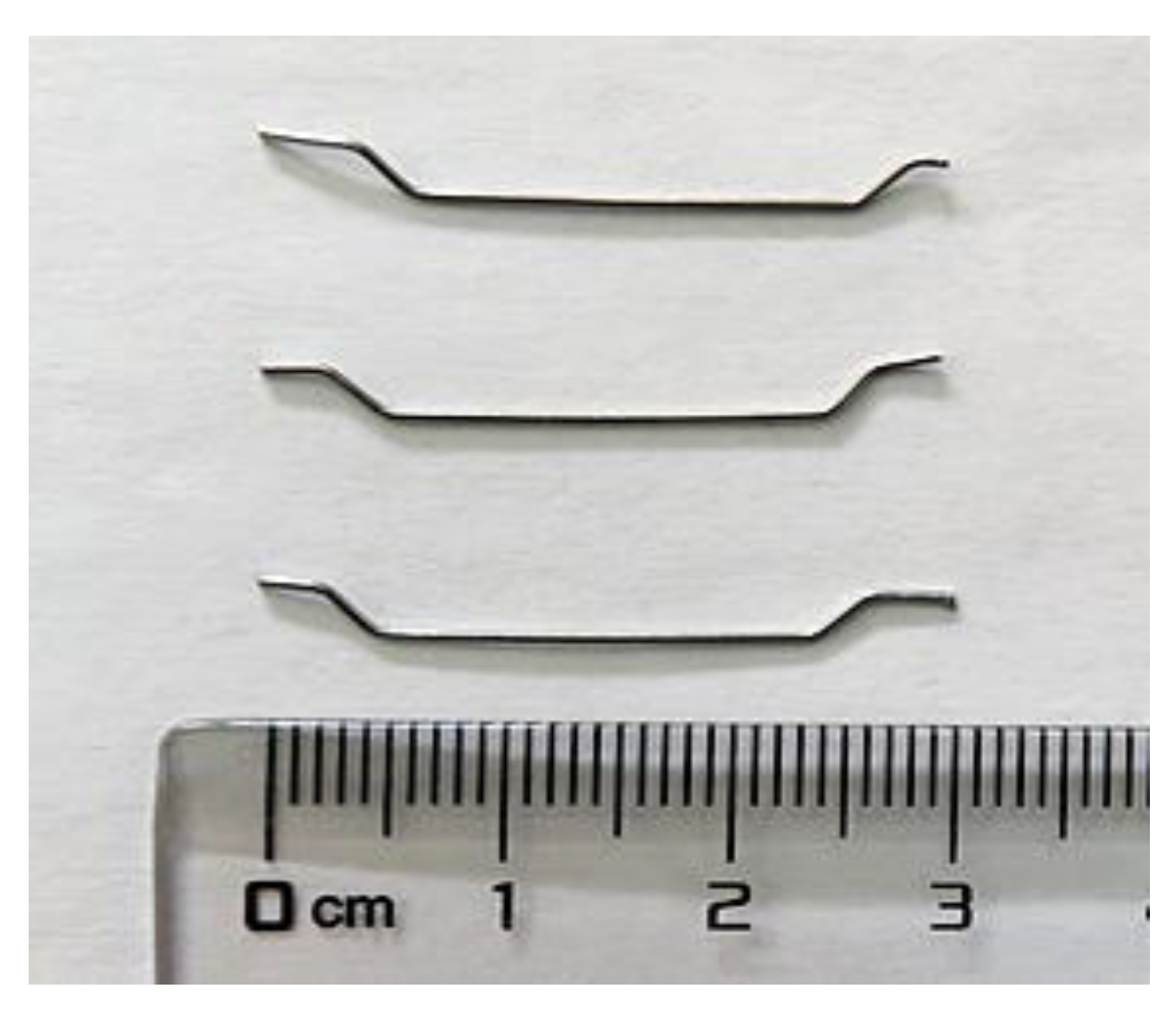
2.1. Materials
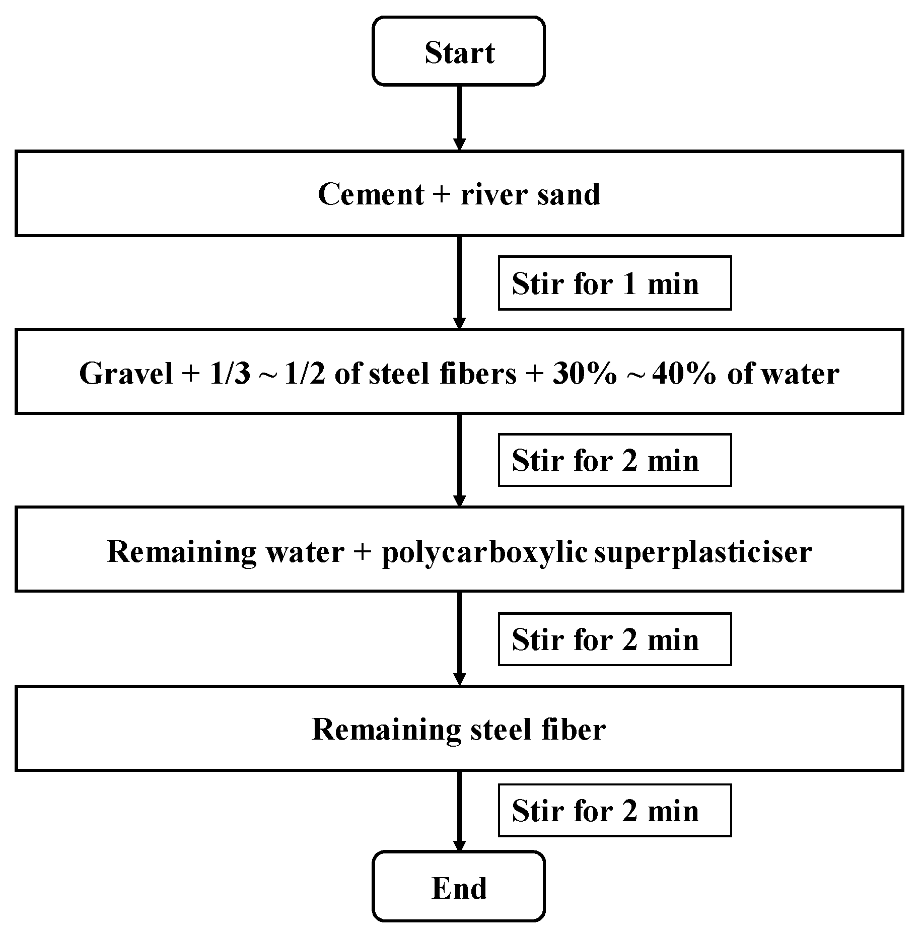
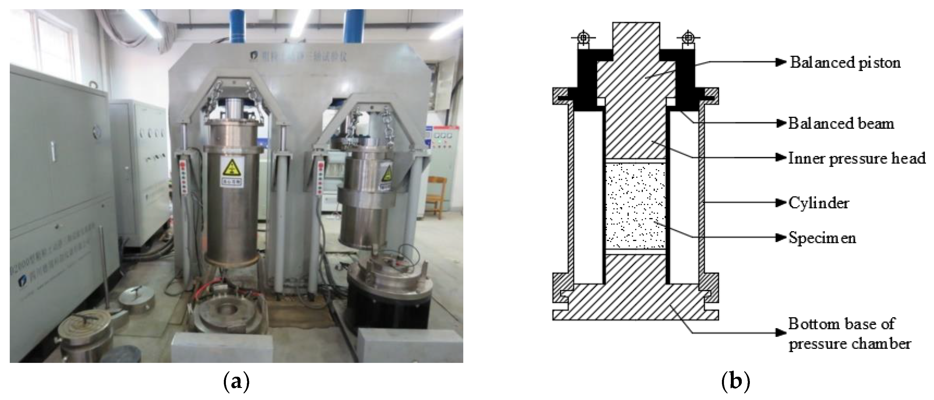
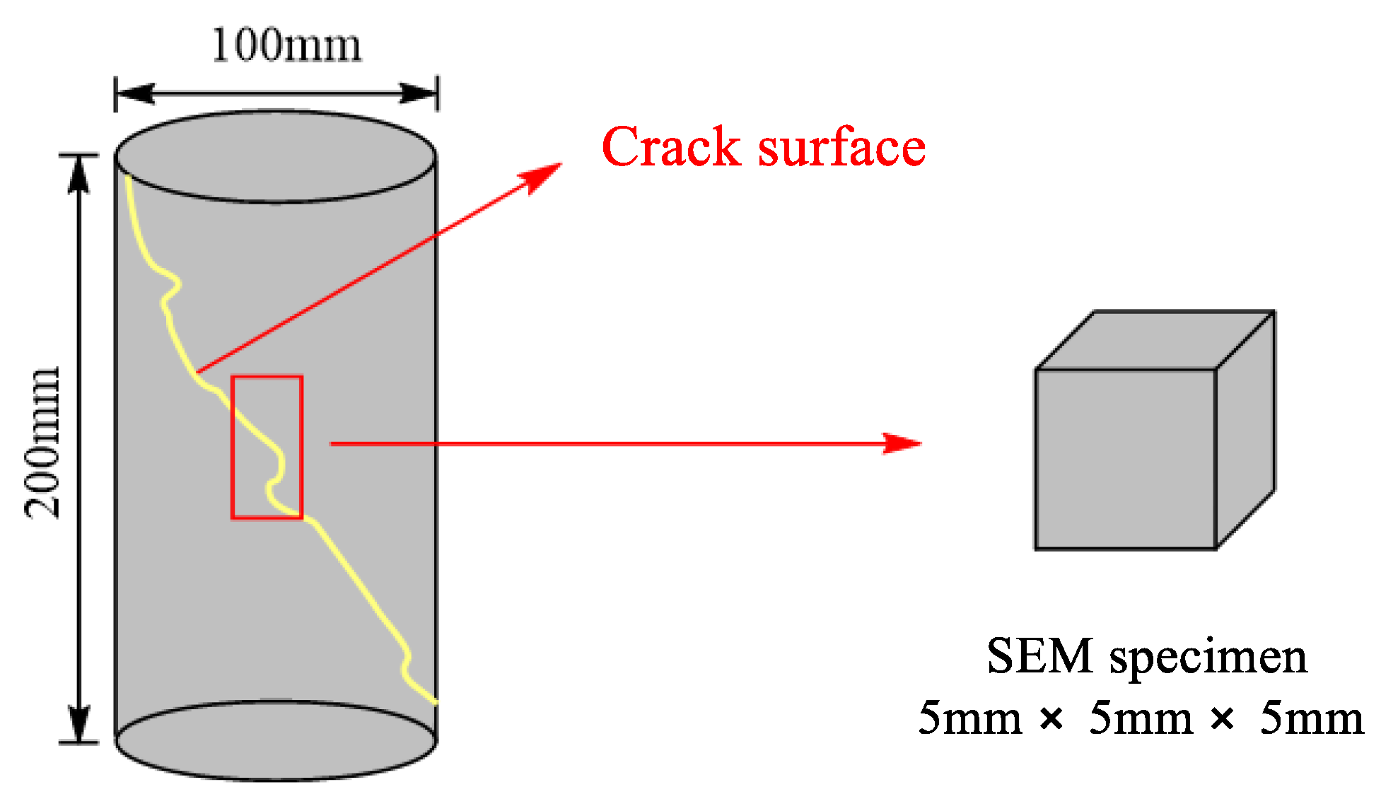
2.2. Experimental Methods
3. Results and Discussion
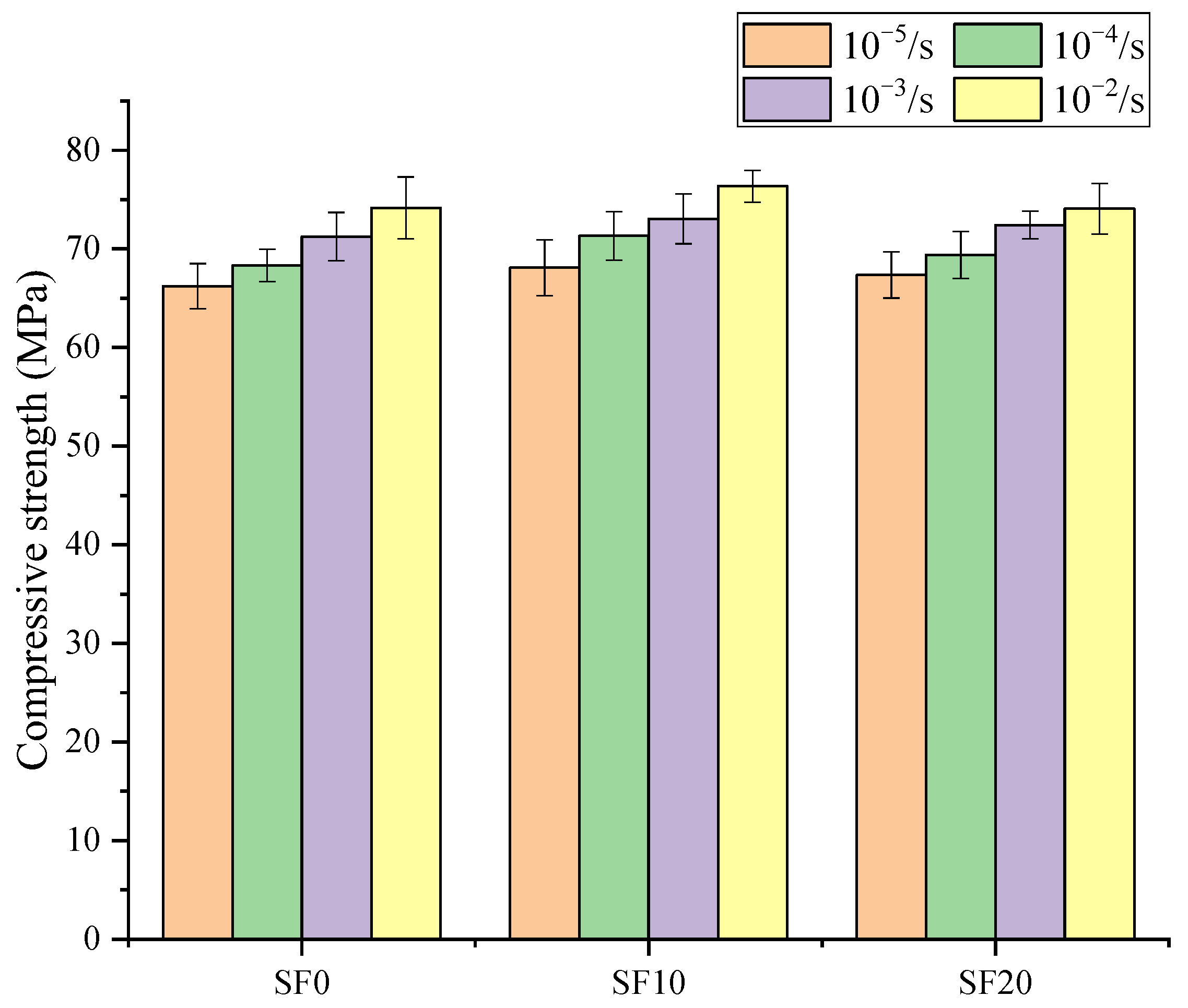
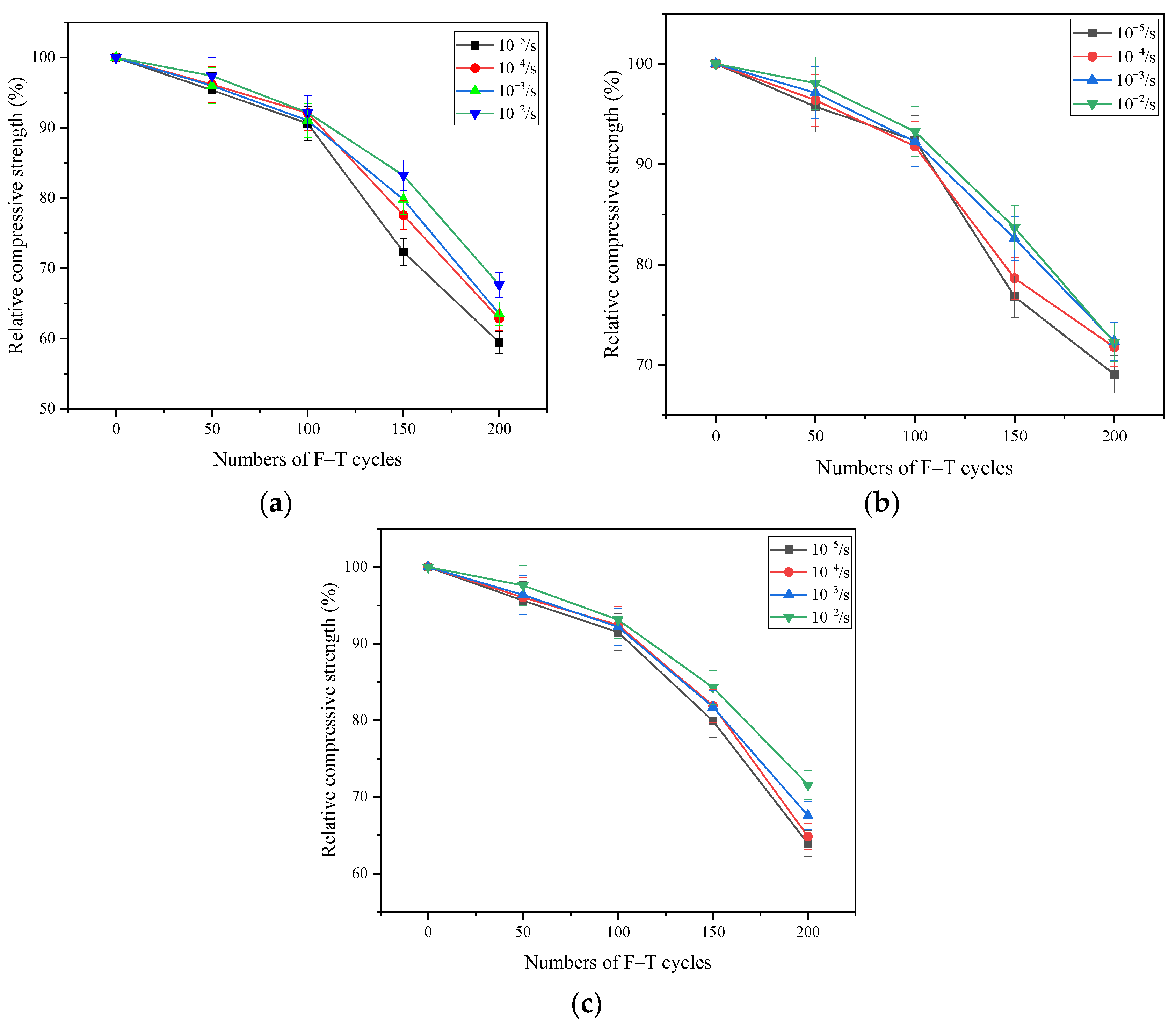
3.1. Triaxial Compressive Strength
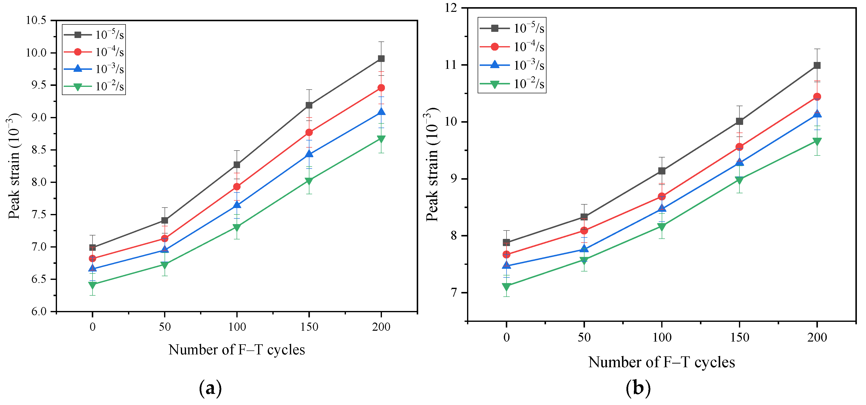
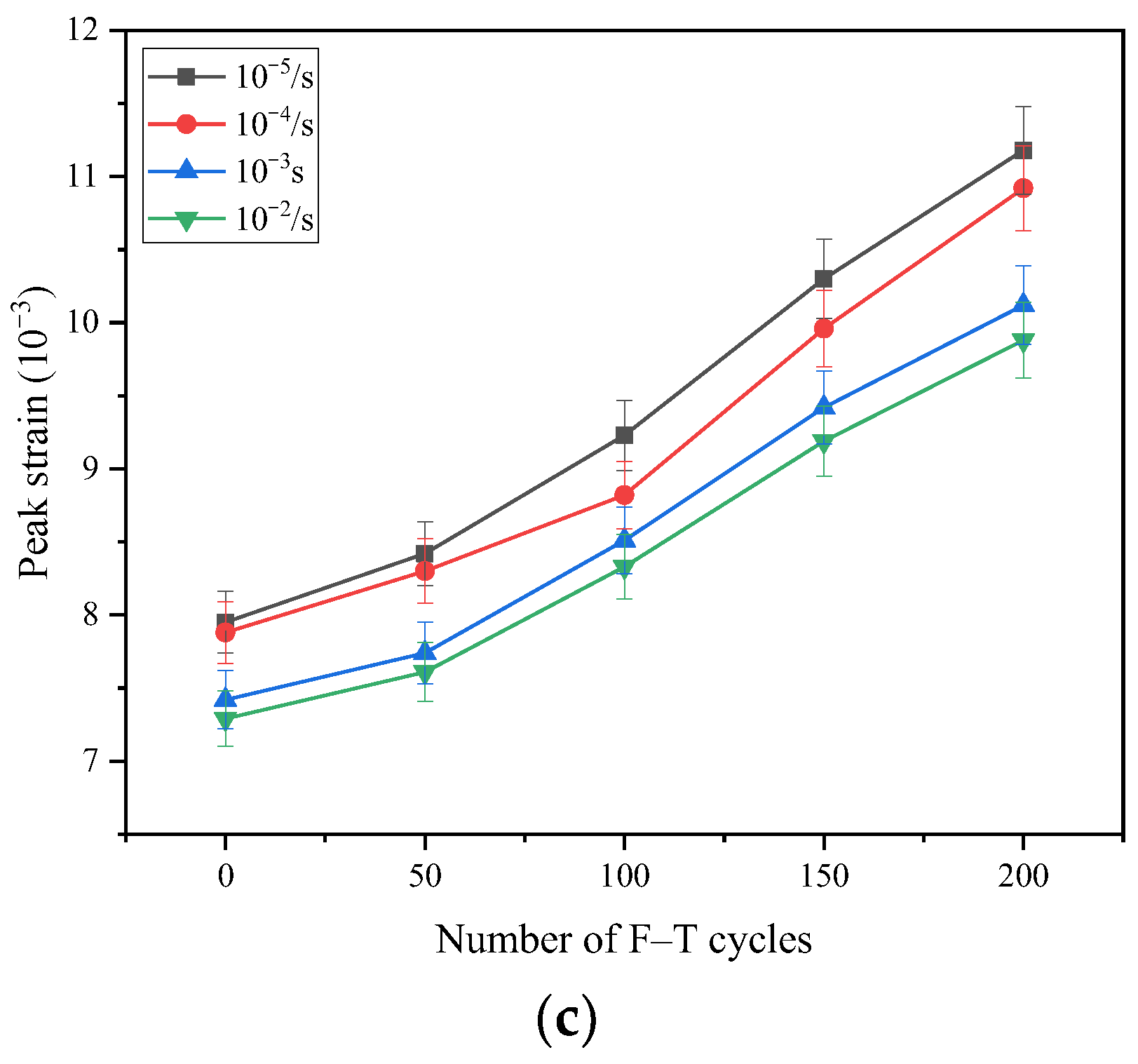
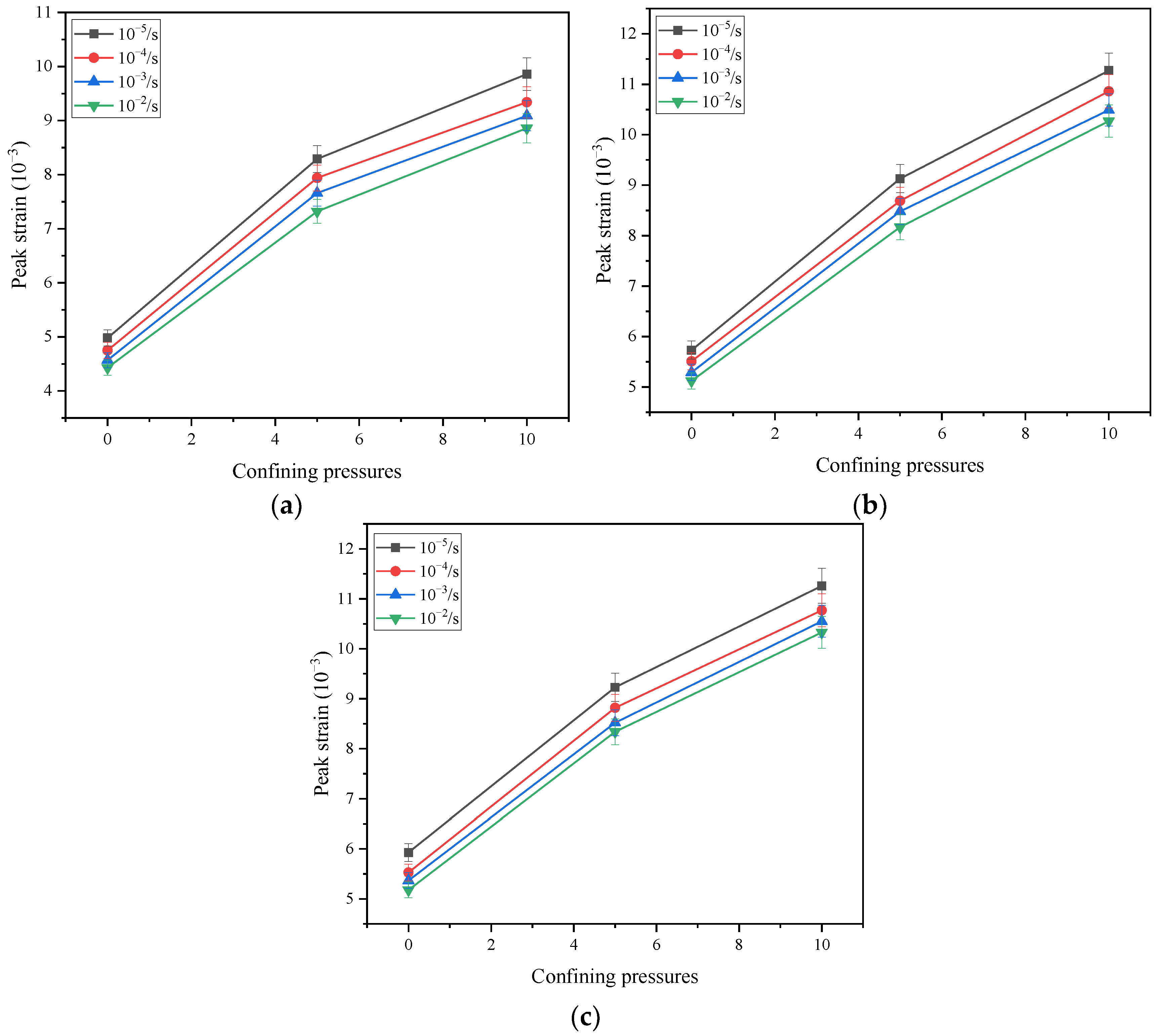
3.2. Peak Strain
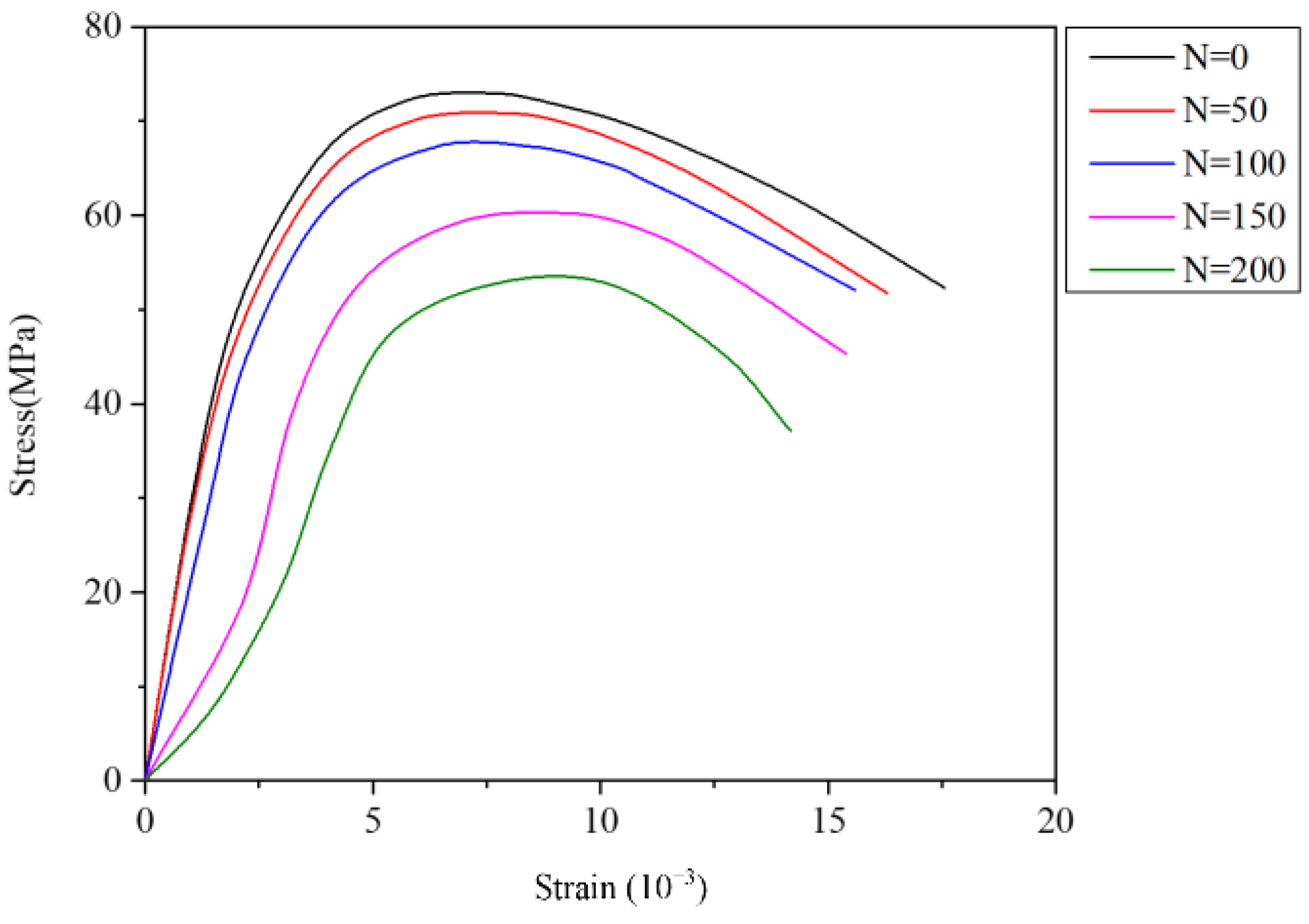
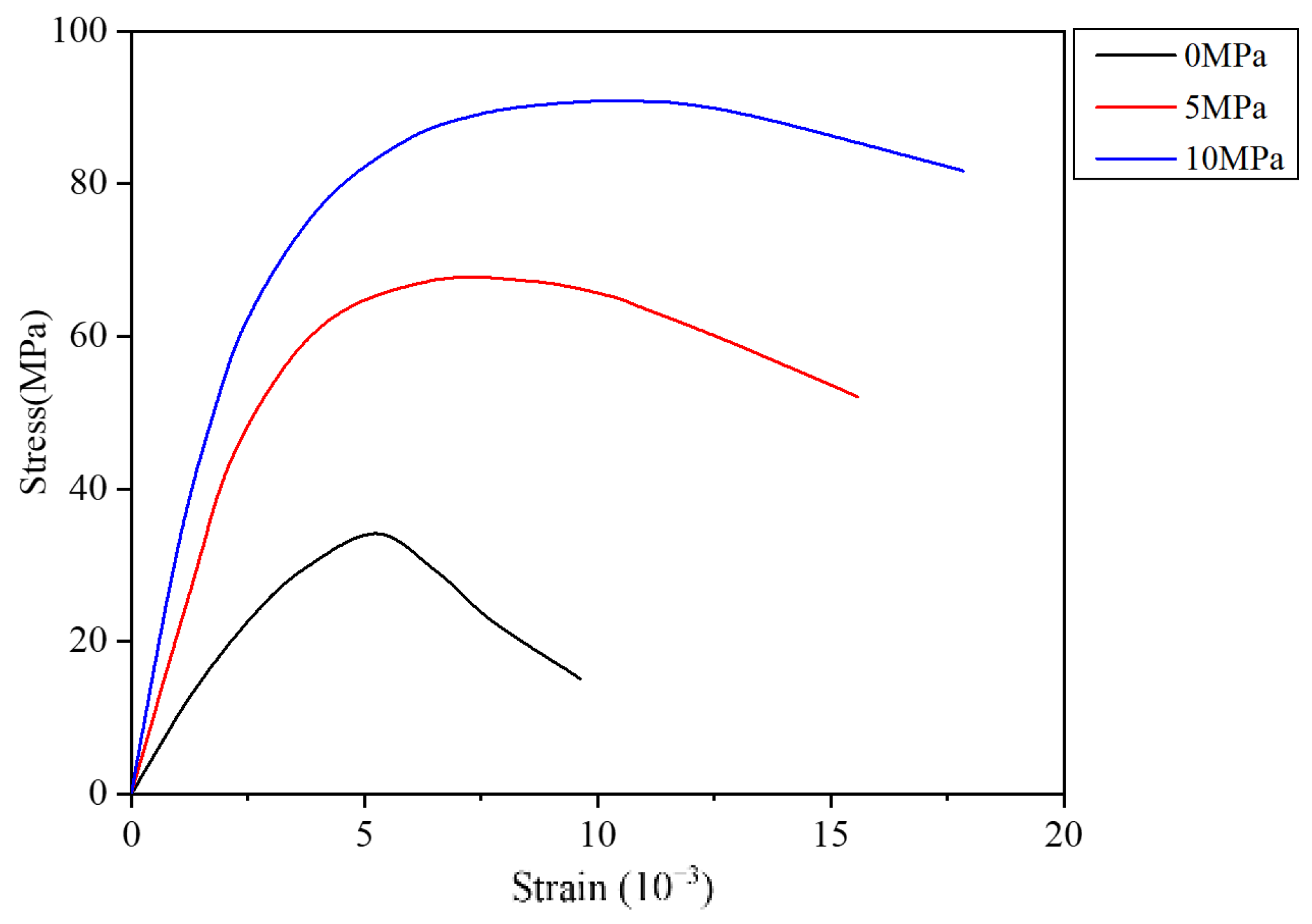
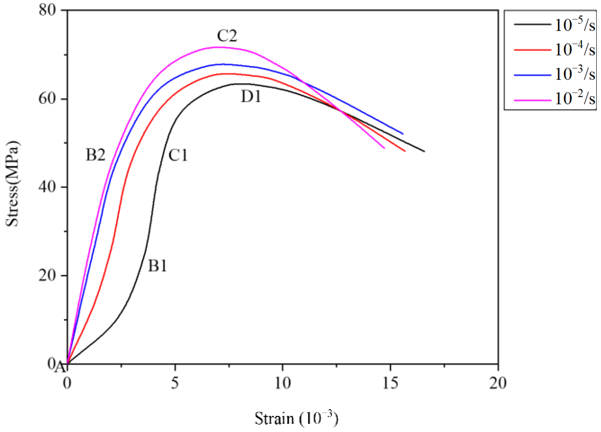
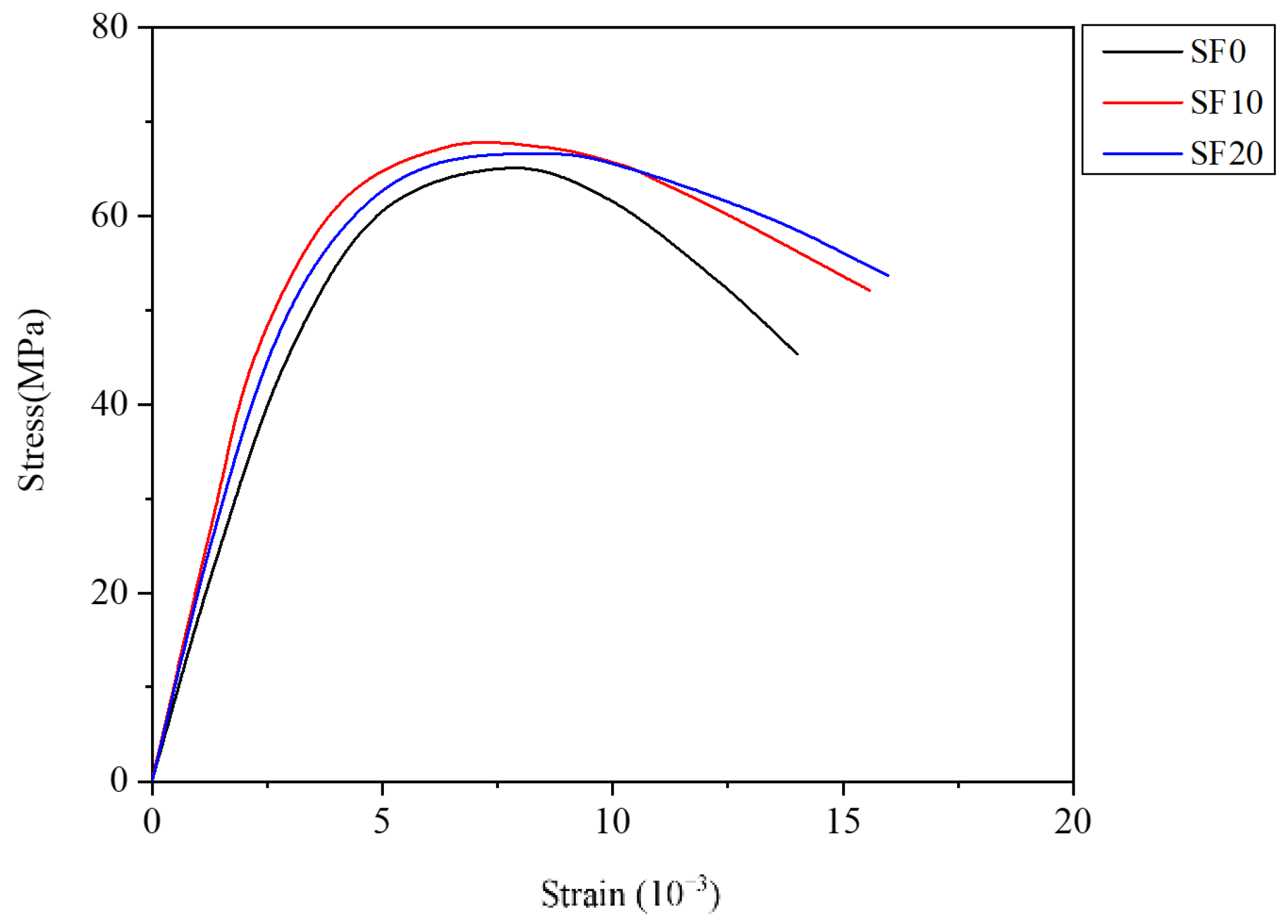
3.3. Axial Stress–Strain Behavior
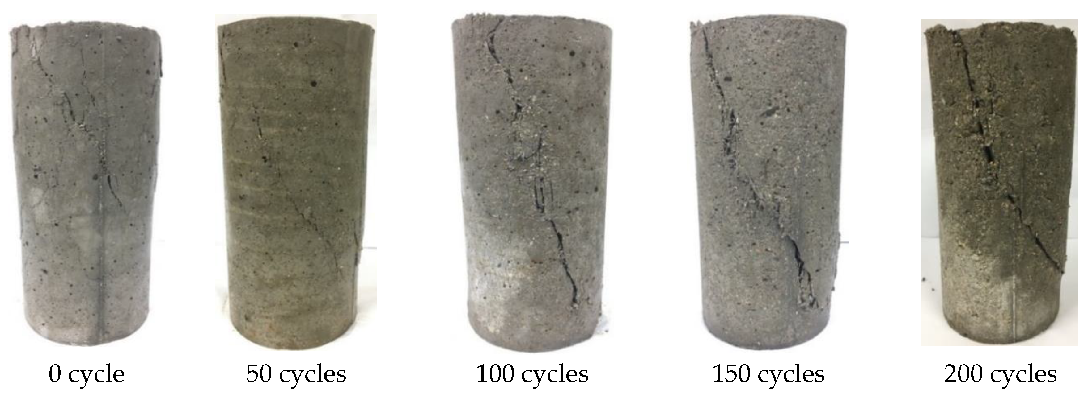
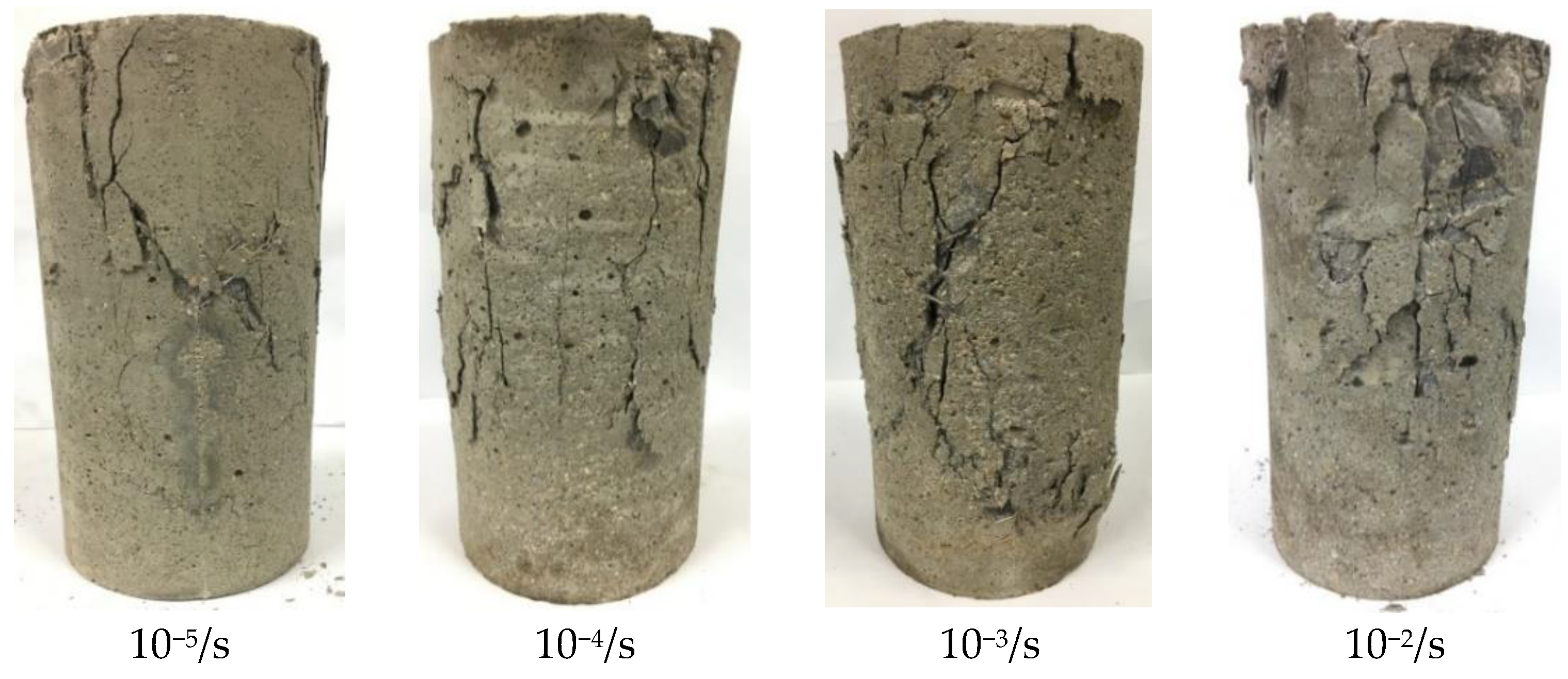
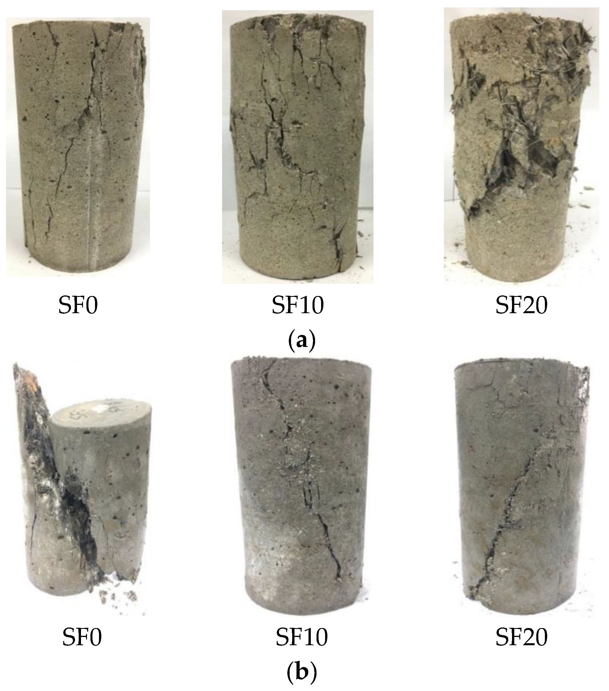
3.4. Failure Mode
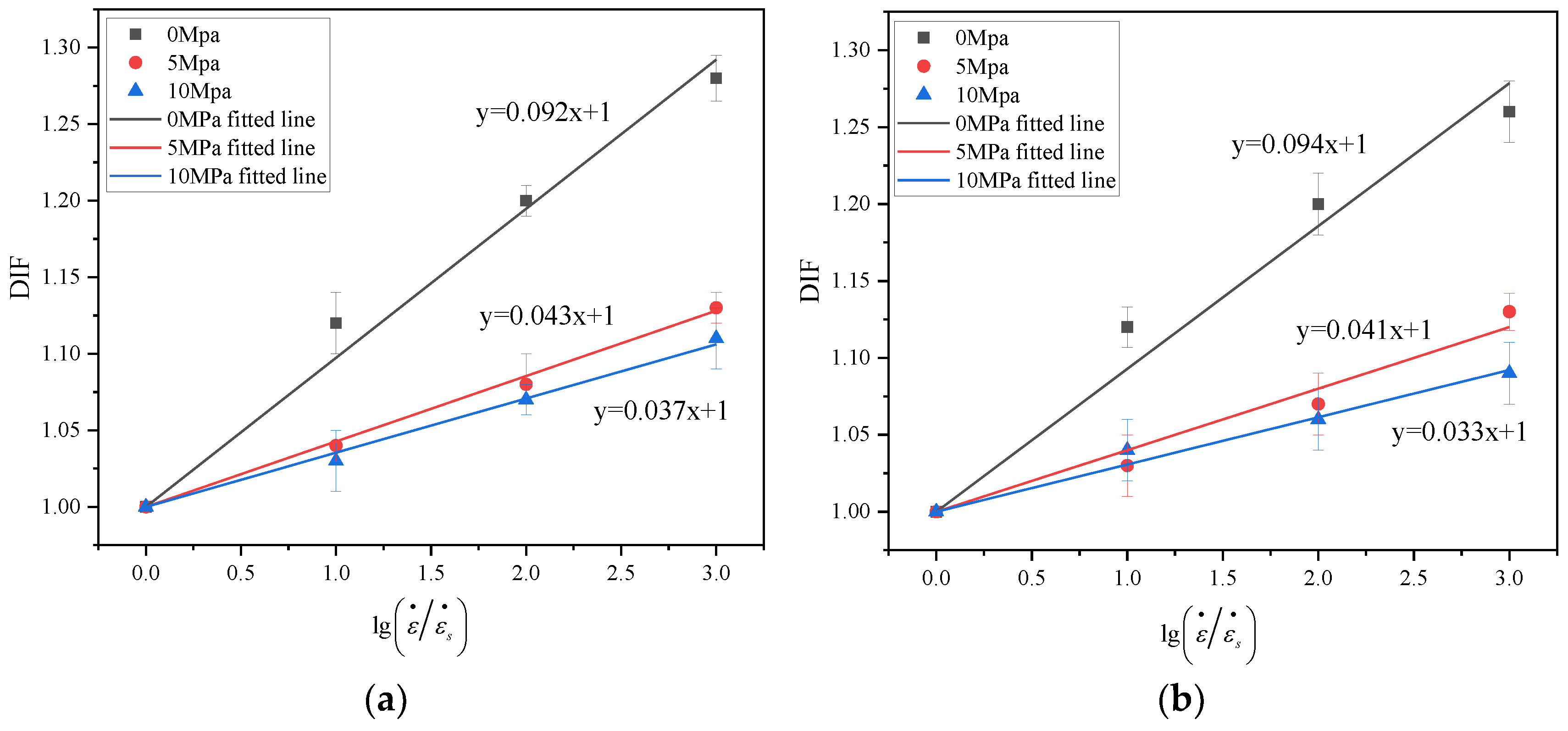
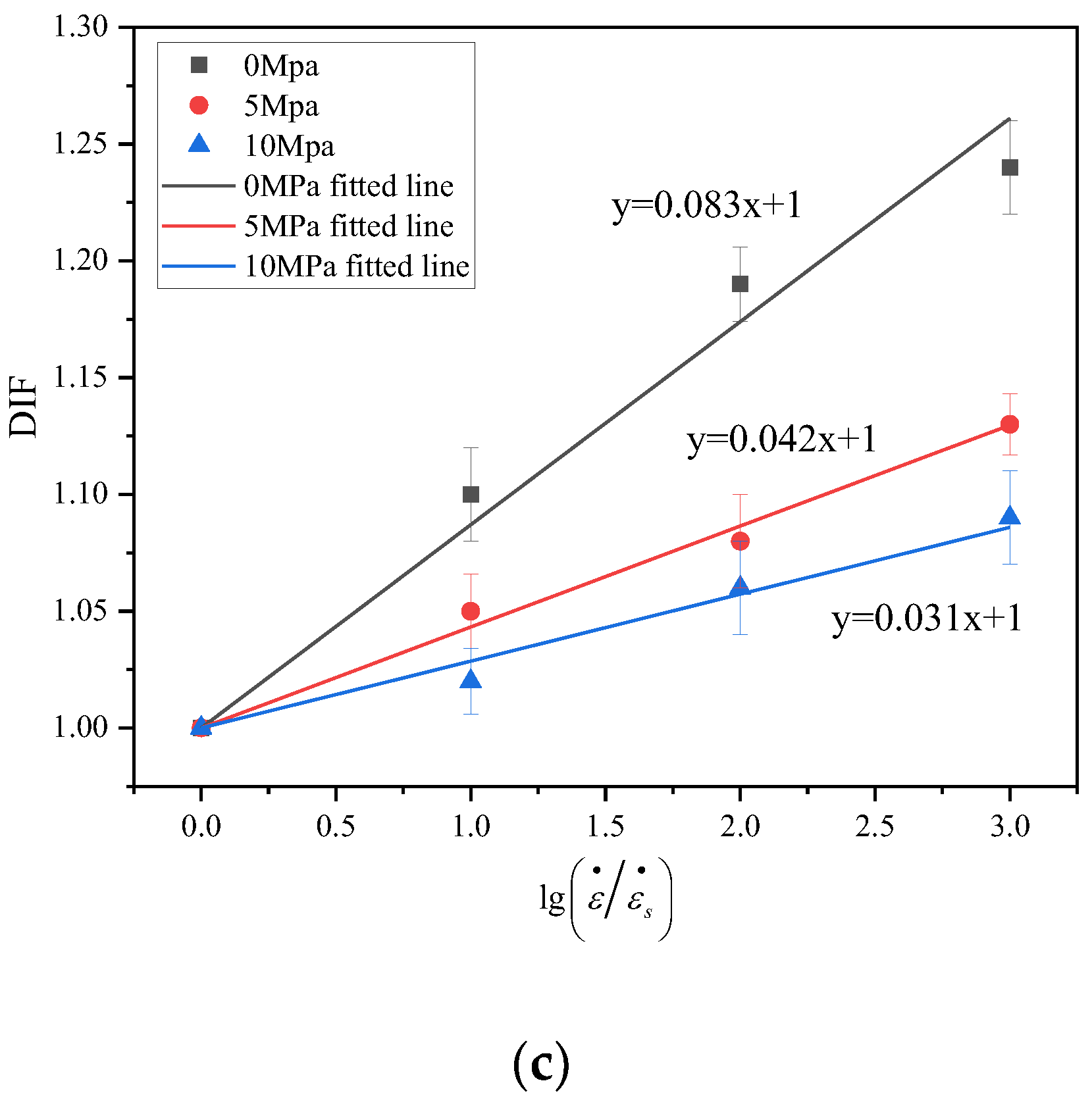
3.5. DIF
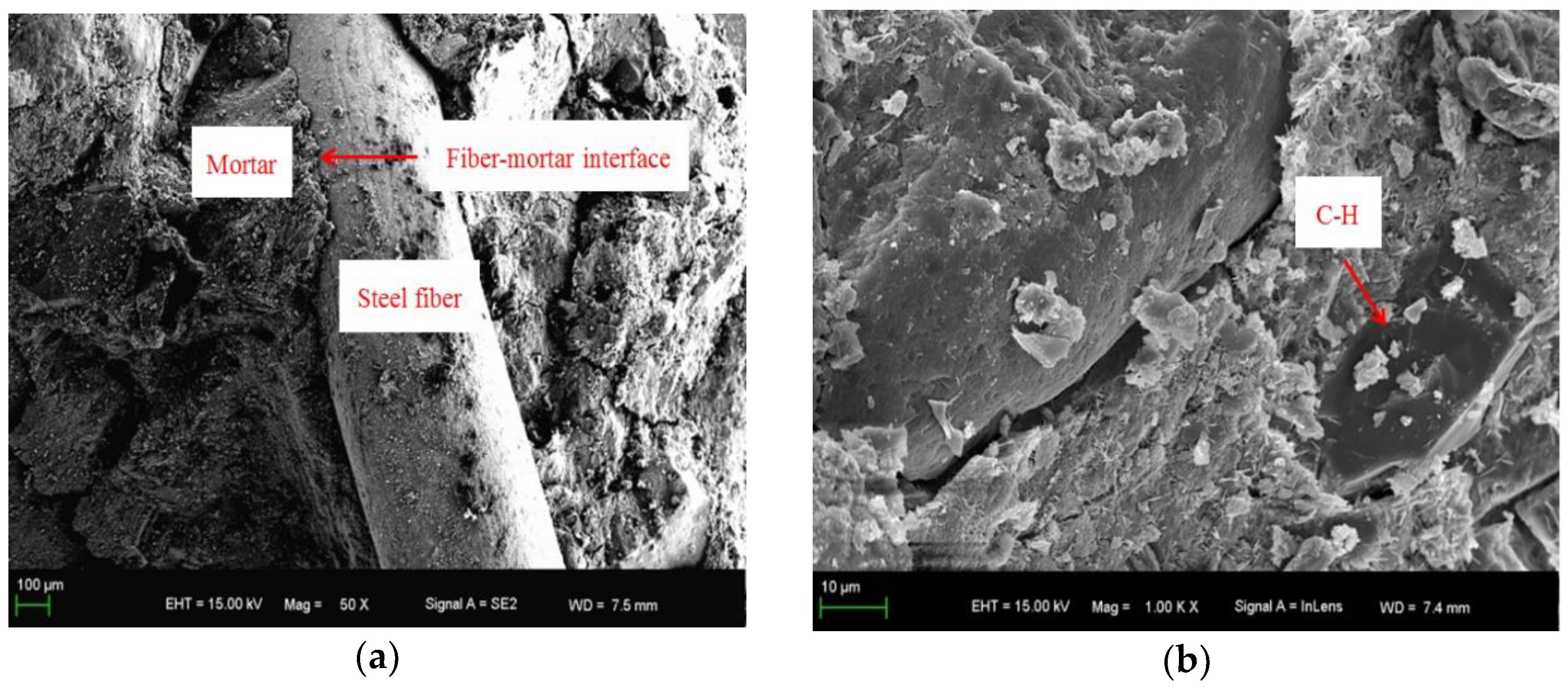
3.6. Microstructure Analysis
4. Conclusions
- (1)
- With increasing F–T cycles, the triaxial compressive strength of concrete specimens declines, the stress–strain curve area decreases with time, and the corresponding energy absorption capacity gradually weakens. However, the failure mode of the concrete did not change, only the deterioration of the specimen gradually increased.
- (2)
- The F–T damage of SFRC shows two stages: (I) from 0 to 50 F–T cycles, the compressive strength of specimens slowly decreases and the peak strain slowly increases; and (II) from 50 to 200 F–T cycles, the compressive strength and peak strain of specimens acceleratingly decreases and increases, respectively. Similarly, mortar shedding and crack extension on the specimen surface were also accelerated in the second stage.
- (3)
- Under F–T cycles, steel fiber can enhance the dynamic mechanical properties of concrete. Adding steel fibers to concrete under F–T cycles increases the triaxial compressive strength, peak strain, and energy absorption capacity. However, increasing steel fiber content to 2.0%, the triaxial compressive strength of concrete decreases because the excessive steel fiber causes a small amount of agglomeration.
- (4)
- As the strain rate increases, the compressive strength of the SFRC subjected to F–T cycles increases gradually, the peak strain decreases slowly and the DIF of strength increases linearly. In low strain rate, SFRC specimens have sufficient time to select the path, most of which are along the mortar interior or the weak surface of aggregate mortar. However, when the strain rate increases, the shape of failure surface of the SFRC changes and a large number of coarse aggregate fractures occur.
- (5)
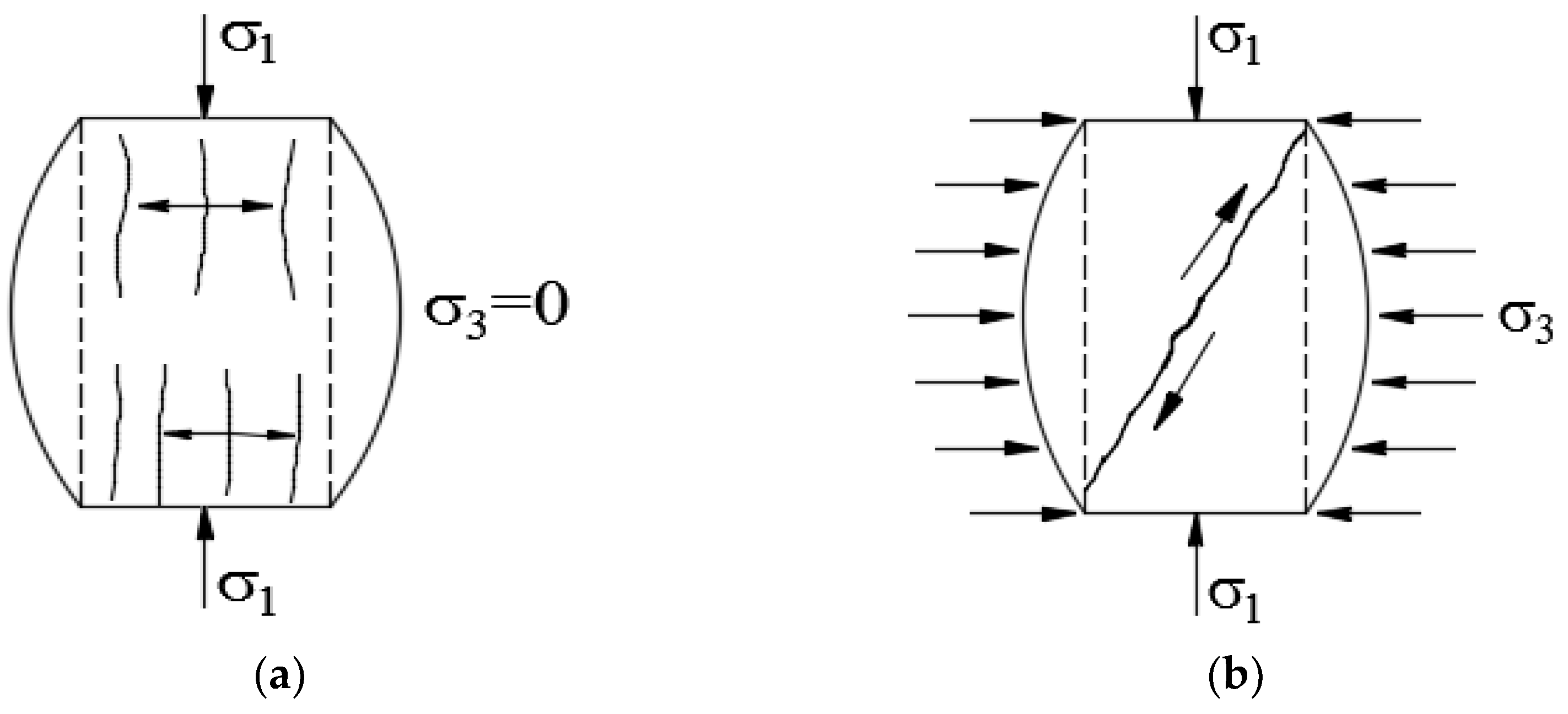
- Under F–T cycles, specimens with no confining pressure exhibit crack directions parallel to loading stress directions, and the cracks are concentrated in the middle of the specimen. However, the steel fiber reinforced concrete specimens change to inclined shear failure under the action of confining pressure. In addition, as confining pressure increased under F–T cycling, SFRC’s triaxial compressive strength increased as well as its peak strain and energy absorption capacity.
- (6)
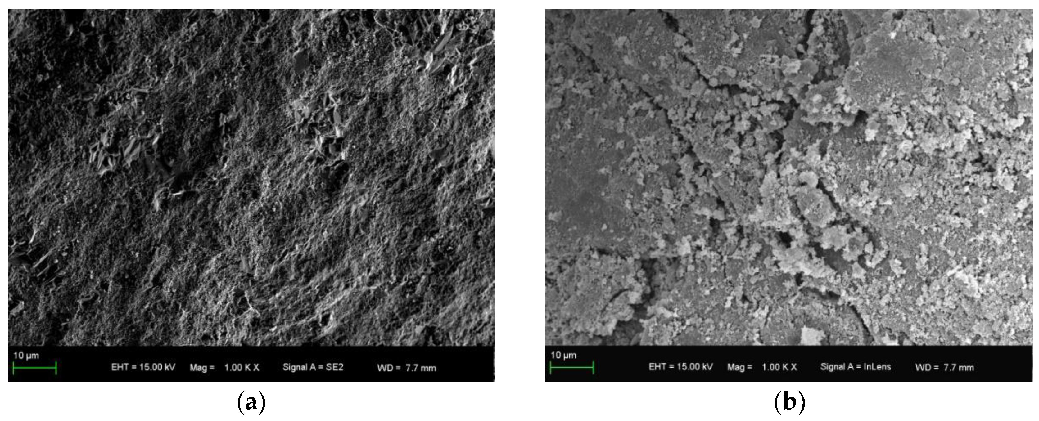
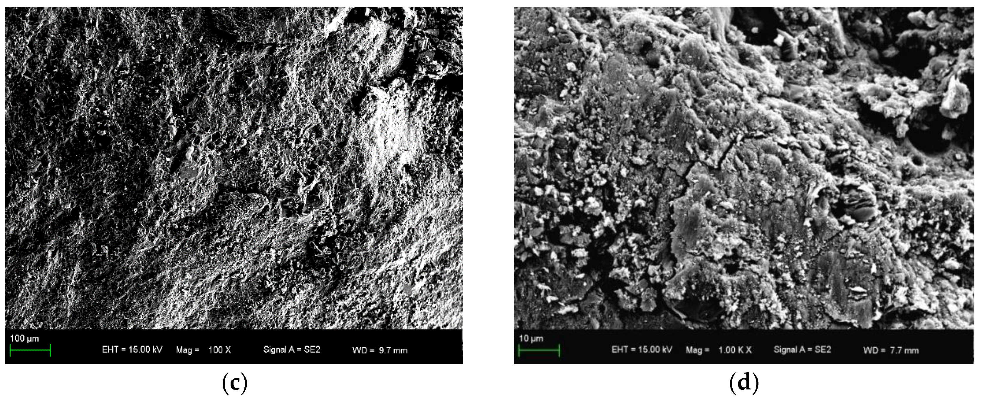
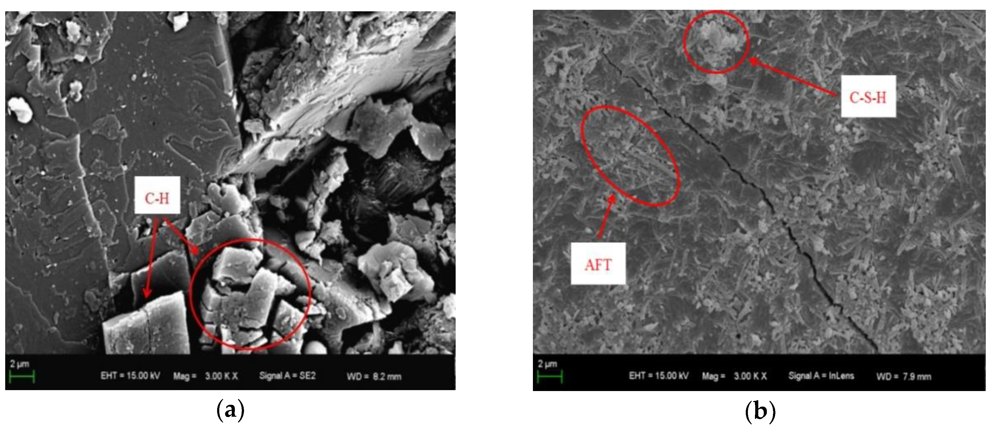
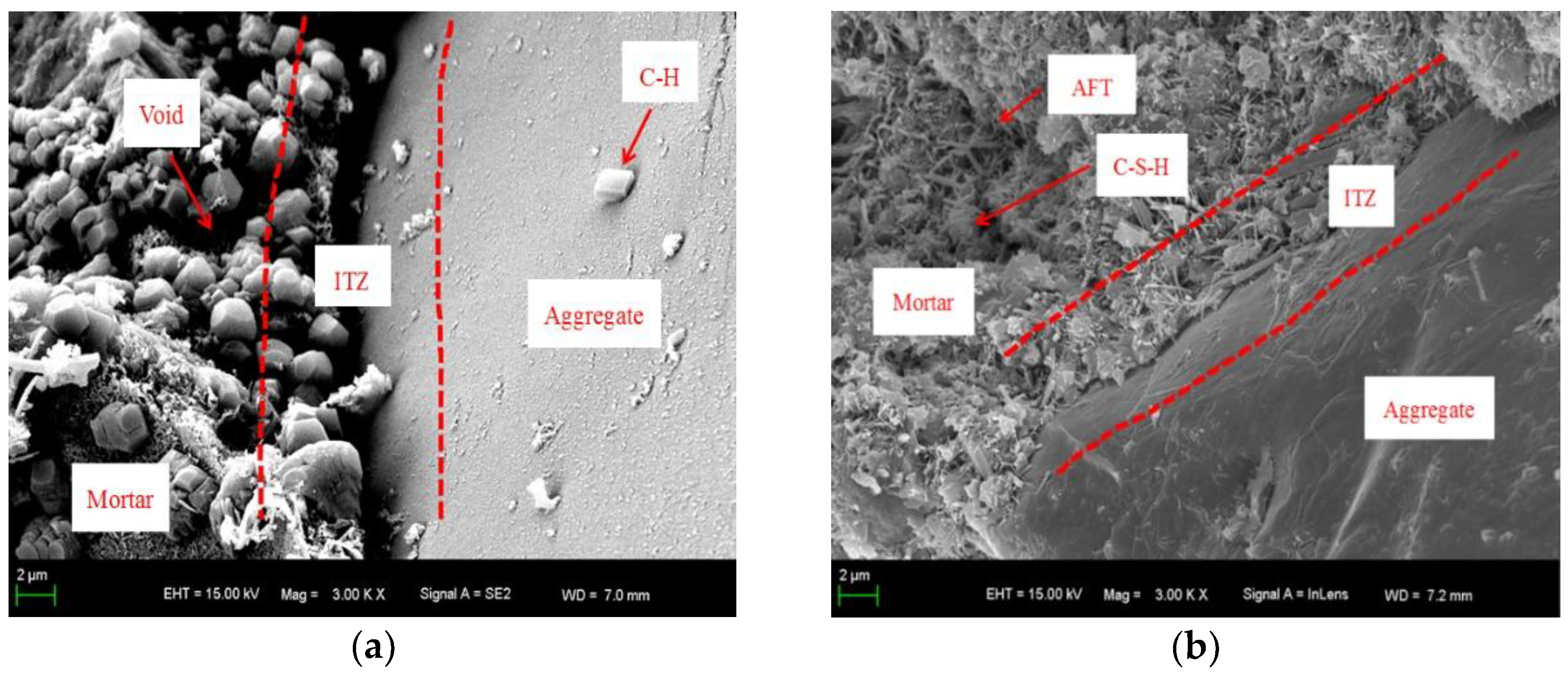
- The SEM tests conducted on concrete specimens after the F–T cycles show that steel fibers enhance the ITZ between aggregates and mortars, compaction and microstructure improvement of concrete. The microstructure analysis results are accordant with the laws of macroscopic properties (compressive strength and peak strain).
Author Contributions
Funding
Data Availability Statement
Conflicts of Interest
References
- Jin, L.; Zhang, R.B.; Tian, Y.D.; Dou, G.Q.; Du, X.L. Experimental investigation on static and dynamic mechanical properties of steel fiber reinforced ultra-high-strength concretes. Constr. Build. Mater. 2018, 178, 102–111. [Google Scholar] [CrossRef]
- Yoo, D.Y.; Banthia, N. Mechanical and structural behaviors of ultra-high-performance fiber-reinforced concrete subjected to impact and blast. Constr. Build. Mater. 2017, 149, 416–431. [Google Scholar] [CrossRef]
- Chen, M.; Chen, W.; Zhong, H.; Chi, D.; Wang, Y.H.; Zhang, M.Z. Experimental study on dynamic compressive behaviour of recycled tyre polymer fibre reinforced concrete. Cem. Concr. Compos. 2019, 98, 95–112. [Google Scholar] [CrossRef]
- Hao, Y.; Hao, H.; Chen, G. Experimental investigation of the behaviour of spiral steel fibre reinforced concrete beams subjected to drop-weight impact loads. Mater. Struct. 2016, 49, 353–370. [Google Scholar] [CrossRef]
- Vairagade, V.S.; Kene, K.S. Strength of normal concrete using metallic and synthetic fibres. Procedia Eng. 2013, 51, 132–140. [Google Scholar] [CrossRef] [Green Version]
- Abbass, W.; Khan, M.I.; Mourad, S. Evaluation of mechanical properties of steel fiber reinforced concrete with different strengths of concrete. Constr. Build. Mater. 2018, 168, 556–569. [Google Scholar] [CrossRef]
- Wang, Z.L.; Wu, J.; Wang, J.G. Experimental and numerical analysis on effect of fibre aspect ratio on mechanical properties of SRFC. Constr. Build. Mater. 2010, 24, 559–565. [Google Scholar] [CrossRef]
- Farhan, N.A.; Sheikh, M.N.; Hadi, M.N.S. Behaviour of Ambient Cured Steel Fibre Reinforced Geopolymer Concrete Columns under Axial and Flexural Loads. Structures 2018, 15, 184–195. [Google Scholar] [CrossRef]
- Yoo, D.Y.; Yoon, Y.S.; Banthia, N. Predicting the post-cracking behavior of normal- and high-strength steel-fiber-reinforced concrete beams. Constr. Build. Mater. 2015, 93, 477–485. [Google Scholar] [CrossRef]
- Yang, D.P.; Zhang, B.; Liu, G.J. Experimental Study on Spall Resistance of Steel-Fiber Reinforced Concrete Slab Subjected to Explosion. Int. J. Concr. Struct. Mater. 2021, 15, 23. [Google Scholar] [CrossRef]
- Domski, J.; Katzer, J. Comprehensive approach to evaluation of mechanical properties of waste aggregate concrete reinforced by steel fiber. Tech. Pap. 2018, 2, 75–453. [Google Scholar] [CrossRef]
- Kantar, E.; Yuen, T.Y.P.; Kobya, V.; Kuang, J.S. Impact dynamics and energy dissipation capacity of fibre-reinforced self-compacting concrete plates. Constr. Build. Mater. 2017, 138, 383–397. [Google Scholar] [CrossRef]
- Farhan, N.A.; Sheikh, M.N.; Hadi, M.N.S. Engineering Properties of Ambient Cured Alkali-Activated Fly Ash–Slag Concrete Reinforced with Different Types of Steel Fiber. J. Mater. Civ. Eng. 2018, 30, 04018142. [Google Scholar] [CrossRef] [Green Version]
- Su, Y.; Li, J.; Wu, C.Q.; Wu, P.T.; Li, Z.X. Effects of steel fibres on dynamic strength of UHPC. Constr. Build. Mater. 2016, 114, 708–718. [Google Scholar] [CrossRef]
- Zhang, P.; Zhen, G.; Wang, J.; Guo, J.J.; Wang, T.Y. Influencing factors analysis and optimized prediction model for rheology and flowability of nano-SiO2 and PVA fiber reinforced alkali-activated composites. J. Clean. Prod. 2022, 366, 132988. [Google Scholar] [CrossRef]
- Wu, H.; Ren, G.M.; Fang, Q.; Liu, J.Z. Effects of steel fiber content and type on dynamic tensile mechanical properties of UHPCC. Constr. Build. Mater. 2018, 173, 251–261. [Google Scholar] [CrossRef]
- Zhang, P.; Han, X.; Hu, S.W.; Wang, J.; Wang, T.Y. High-temperature behavior of polyvinyl alcohol fiber-reinforced metakaolin/fly ash-based geopolymer mortar. Compos. Part B Eng. 2022, 244, 110171. [Google Scholar] [CrossRef]
- Fang, Q.; Zhang, J. Three-dimensional modelling of steel fiber reinforced concrete material under intense dynamic loading. Constr. Build. Mater. 2013, 44, 118–132. [Google Scholar] [CrossRef]
- Zhang, P.; Wang, W.S.; Lv, Y.J.; Wang, K.X.; Dai, S.Y. Effect of polymer coatings on the freezing–thawing and carbonation resistances of nano-SiO2 and polyvinyl alcohol fiber-reinforced cementitious composites. J. Mater. Res. Technol. 2022, 21, 69–83. [Google Scholar] [CrossRef]
- Ren, G.M.; Wu, H.; Fang, Q.; Liu, J.Z. Effects of steel fiber content and type on dynamic compressive mechanical properties of UHPCC. Constr. Build. Mater. 2018, 164, 29–43. [Google Scholar] [CrossRef]
- Lu, X.B.; Thoms, H.C.T. Behavior of high strength concrete with and without steel fiber reinforcement in triaxial compression. Cem. Concr. Res. 2006, 36, 1679–1685. [Google Scholar] [CrossRef]
- Li, Y.; Zhou, Y.; Wang, R.J. Experimental investigation on the properties of the interface between RCC layers subjected to early-age frost damage. Cem. Concr. Compos. 2022, 134, 104745. [Google Scholar] [CrossRef]
- Noori, A.; Shekarchi, M.; Moradian, M.; Moosavi, M. Behavior of steel fiber-reinforced cementitious mortar and high-performance concrete in triaxial loading. ACI Mater. J. 2015, 112, 95–103. [Google Scholar] [CrossRef]
- Foltz, R.R.; Lee, D.H.; LaFave, J.M. Biaxial behavior of high-performance fiber-reinforced cementitious composite plates. Constr. Build. Mater. 2017, 143, 501–514. [Google Scholar] [CrossRef] [Green Version]
- Bao, J.W.; Wang, L.C.; Zhang, Q.Y.; Liang, Y.Q.; Jiang, P.Q.; Song, Y.P. Combined effects of steel fiber and strain rate on the biaxial compressive behavior of concrete. Constr. Build Mater. 2018, 187, 394–405. [Google Scholar] [CrossRef]
- Liu, D.X.; Xu, W.N.; Cheng, Z.L.; Zhou, Z.J.; Cai, X.Y.; Zhao, B.Q. Improvement test on frost resistance of vegetation-concrete and engineering application of test fruitage. Environ. Earth Sci. 2013, 69, 161–170. [Google Scholar]
- Zhang, W.M.; Chen, S.H.; Zhang, N.; Zhou, Y. Low-velocity flexural impact response of steel fiber reinforced concrete subjected to freeze–thaw cycles in NaCl solution. Constr. Build. Mater. 2015, 101, 522–526. [Google Scholar] [CrossRef]
- Li, L.; Zhang, Y.; Shi, Y. Surface Cracking and Fractal Characteristics of Cement Paste after Exposure to High Temperatures. Fractal Fract. 2022, 6, 465. [Google Scholar] [CrossRef]
- Miao, C.W.; Mu, R.; Tian, Q.; Sun, W. Effect of sulfate solution on the frost resistance of concrete with and without steel fiber reinforcement. Cem. Concr. Res. 2002, 32, 31–34. [Google Scholar] [CrossRef]
- Niu, D.T.; Jinag, L.; Bai, M.; Miao, Y.Y. Study of the performance of steel fiber reinforced concrete to water and salt freezing condition. Constr. Build. Mater. 2013, 44, 267–273. [Google Scholar] [CrossRef]
- Wang, R.J.; Hu, Z.Y.; Li, Y.; Wang, K.; Zhang, H. Review on the deterioration and approaches to enhance the durability of concrete in the freeze–thaw environment. Constr. Build. Mater. 2022, 321, 126371. [Google Scholar] [CrossRef]
- GB 175–2007; Common Portland Cements. General Administration of Quality Supervision. Inspection and Quarantine of the People’s Republic of China and Standardization Administration of the People’s Republic of China: Beijing, China, 2008.
- CECS 13: 2009; Standard Test Methods for Fiber Reinforced Concrete. Chinese Association for Engineering Construction Standardization: Beijing, China, 2009.
- GB/T 50082–2009; Standard for Long Term Durability Test Method of Ordinary Concrete. Ministry of Housing and Urban Rural Development of the People’s Republic of China: Beijing, China, 2009.
- Lu, J.Z.; Zhu, K.F.; Tian, L.Z.; Guo, L. Dynamic compressive strength of concrete damaged by fatigue loading and freeze-thaw cycling. Constr. Build. Mater. 2017, 152, 847–855. [Google Scholar] [CrossRef]
- Wang, Q.F.; Liu, Y.H.; Peng, G. Effect of water pressure on mechanical behavior of concrete under dynamic compression state. Constr. Build. Mater. 2016, 125, 501–509. [Google Scholar] [CrossRef]
- Wang, H.; Wang, L.C.; Song, Y.P.; Wang, J.Z. Influence of free water on dynamic behavior of dam concrete under biaxial compression. Constr. Build. Mater. 2016, 112, 222–231. [Google Scholar] [CrossRef]
- Reinhardt, H.W.; Cornelissen, H.A.W.; Hordijk, D.A. Tensile tests and failure analysis of concrete. J. Struct. Eng. 1986, 112, 2462–2477. [Google Scholar] [CrossRef]
- Rossi, P.; Boulay, C. Influence of free-water in concrete on the cracking process. Mag. Concr. Res. 1990, 42, 143–146. [Google Scholar] [CrossRef]
- Rossi, P. Influence of cracking in the presence of free water on the mechanical behaviour of concrete. Mag. Concr. Res. 1991, 43, 53–57. [Google Scholar] [CrossRef]
- Rossi, P.; Vanmier, J.G.M.; Toutlemonde, F.; Le Maou, F.; Boulay, C. Effect of loading rate on the strength of concrete subjected to uniaxial tension. Mater. Struct. 1994, 169, 260–264. [Google Scholar] [CrossRef]
- Kytinou, V.K.; Chalioris, C.E.; Karayannis, C.G. Analysis of Residual Flexural Stiffness of Steel FiberReinforced Concrete Beams with Steel Reinforcement. Materials 2020, 13, 2698. [Google Scholar] [CrossRef]
- Emmanuel, E.A.; Messaoud, S.; Adegoke, O.O.; Mark, T. Effect of mix design methods on the mechanical properties of steel fibre-reinforced concrete prepared with recycled aggregates from precast waste. Structures 2020, 27, 664–672. [Google Scholar]
- Wang, R.J.; Zhang, Q.J.; Li, Y. Deterioration of concrete under the coupling effects of freeze–thaw cycles and other actions: A review. Constr. Build. Mater. 2022, 319, 126045. [Google Scholar] [CrossRef]
- Fu, Q.; Xu, W.R.; Li, D.; Li, N.; Niu, D.T.; Zhang, L.; Guo, B.B.; Zhang, Y.L. Dynamic compressive behaviour of hybrid basalt-polypropylene fibre-reinforced concrete under confining pressure: Experimental characterisation and strength criterion. Cem. Concr. Compos. 2021, 118, 103954. [Google Scholar] [CrossRef]
- Chen, Z.; Hu, Y.; Li, Q.B.; Sun, M.Y.; Lu, P.Y.; Liu, T.Y. Behavior of concrete in water subjected to dynamic triaxial compression. J. Eng. Mech. 2010, 136, 379–389. [Google Scholar] [CrossRef]
- Xiao, J.Z.; Li, L.; Shen, L.M.; Poon, C.S. Compressive behaviour of recycled aggregate concrete under impact loading. Cem. Concr. Res. 2015, 71, 46–55. [Google Scholar] [CrossRef]
- Li, L.; Poon, C.S.; Xiao, J.Z.; Xuan, D.X. Effect of carbonated recycled coarse aggregate on the dynamic compressive behavior of recycled aggregate concrete. Constr. Build. Mater. 2017, 151, 52–62. [Google Scholar] [CrossRef]
- Xiao, J.Z.; Li, L.; Shen, L.M.; Yuan, J.Q. Effects of strain rate on mechanical behavior of modeled recycled aggregate concrete under uniaxial compression. Constr. Build. Mater. 2015, 93, 214–222. [Google Scholar] [CrossRef]
- Guler, S.; Akbulut, Z.F. Residual strength and toughness properties of 3D, 4D and 5D steel fiber-reinforced concrete exposed to high temperatures. Constr. Build. Mater. 2022, 327, 126945. [Google Scholar] [CrossRef]
- Chen, Y.L.; Chen, Z.P.; Xu, J.J.; Liu, E.M.; Wu, B. Performance evaluation of recycled aggregate concrete under multiaxial compression. Constr. Build. Mater. 2019, 229, 116935. [Google Scholar] [CrossRef]
- Wang, L.P.; Li, N.; Qi, J.L.; Tian, Y.Z.; Xu, S.H. A study on the physical index change and triaxial compression test of intact hard rock subjected to freeze–thaw cycles. Cold Reg. Sci. Technol. 2019, 160, 39–47. [Google Scholar]
- Kaplan, S.A. Factors affecting the relationship between rate of loading and measured compressive strength of concrete. Mag. Concr. Res. 1980, 32, 79–88. [Google Scholar] [CrossRef]
- Rossi, P.; Toutlemonde, F. Effect of loading rate on the tensile behaviour of concrete: Description of the physical mechanisms. Mater. Struct. 1996, 29, 116–118. [Google Scholar] [CrossRef]
- Zhang, Z.X.; Kou, S.Q.; Yu, J.; Yu, Y.; Jiang, L.G.; Lindqvist, P.A. Effects of loading rate on rock fracture. Int. J. Rock Mech. Min. Sci. 1999, 36, 597–611. [Google Scholar] [CrossRef]
- Li, H.B.; Zhao, J.; Li, T.J. Micromechanical modelling of the mechanical properties of a granite under dynamic uniaxial compressive loads. Int. J. Rock Mech. Min. Sci. 2000, 37, 923–935. [Google Scholar] [CrossRef]
- Li, J.J.; Niu, J.G.; Wan, C.J.; Jin, B.; Yin, Y.L. Investigation on mechanical properties and microstructure of high performance polypropylene fiber reinforced lightweight aggregate concrete. Constr. Build. Mater. 2016, 118, 27–35. [Google Scholar] [CrossRef]
- Wang, R.J.; Yu, N.N.; Li, Y. Methods for improving the microstructure of recycled concrete aggregate: A review. Constr. Build. Mater. 2020, 242, 118164. [Google Scholar] [CrossRef]
- Lerch, J.O.; Bester, H.L.; Van Rooyen, A.S.; Combrinck, R.; Villiers, W.I.; Boshoff, W.P. The effect of mixing on the performance of macro synthetic fiber reinforced concrete. Cem. Concr. Res. 2018, 103, 130–139. [Google Scholar] [CrossRef]
- Wen, C.C.; Zhang, P.; Wang, J.; Hu, S.W. Influence of fibers on the mechanical properties and durability of ultra-high-performance concrete: A review. J. Build. Eng. 2022, 52, 104370. [Google Scholar] [CrossRef]


| Contents | Cement |
|---|---|
| SiO2 (%) | 21.45 |
| Al2O3 (%) | 6.45 |
| CaO (%) | 61.5 |
| Fe2O3 (%) | 3.09 |
| MgO (%) | 1.21 |
| K2O (%) | 1.38 |
| Na2O (%) | 0.25 |
| SO3 (%) | 2.01 |
| Loss on ignition (%) | 4.05 |
| Specific gravity (g/cm3) | 3.15 |
| Properties | Natural Sand | Coarse Aggregate |
|---|---|---|
| Water absorption (%) | 0.79 | 0.76 |
| Loose bulk density (kg/m³) | 1678 | 1430 |
| Length (mm) | Diameter (mm) | Aspect Ratio (l/d) | Elastic Modulus (GPa) | Tensile Strength (MPa) | Density (kg/m3) |
|---|---|---|---|---|---|
| 30 | 0.5 | 60 | 200 | 1195 | 7.85 |
| Specimens ID * | Water | Cement | Sand | Coarse Aggregate | SUPERPLASTICIZER | Steel Fibers |
|---|---|---|---|---|---|---|
| SF0 | 150 | 375 | 765 | 1135 | 2.63 | 0 |
| SF10 | 150 | 375 | 730 | 1095 | 2.63 | 78 |
| SF20 | 150 | 375 | 710 | 1045 | 2.63 | 156 |
| Specimens ID | Confining Pressure (MPa) | k | R2 |
|---|---|---|---|
| SF0 | 0 | 0.0981 | 0.9813 |
| 5 | 0.0430 | 0.9942 | |
| 10 | 0.0369 | 0.9912 | |
| SF10 | 0 | 0.0938 | 0.9604 |
| 5 | 0.0406 | 0.9780 | |
| 10 | 0.0331 | 0.9868 | |
| SF20 | 0 | 0.0874 | 0.9813 |
| 5 | 0.0433 | 0.9944 | |
| 10 | 0.0296 | 0.9795 |
Publisher’s Note: MDPI stays neutral with regard to jurisdictional claims in published maps and institutional affiliations. |
© 2022 by the authors. Licensee MDPI, Basel, Switzerland. This article is an open access article distributed under the terms and conditions of the Creative Commons Attribution (CC BY) license (https://creativecommons.org/licenses/by/4.0/).
Share and Cite
Li, Y.; Zhang, Q.; Wang, R.; Xiong, X.; Li, Y.; Wang, J. Experimental Investigation on the Dynamic Mechanical Properties and Microstructure Deterioration of Steel Fiber Reinforced Concrete Subjected to Freeze–Thaw Cycles. Buildings 2022, 12, 2170. https://doi.org/10.3390/buildings12122170
Li Y, Zhang Q, Wang R, Xiong X, Li Y, Wang J. Experimental Investigation on the Dynamic Mechanical Properties and Microstructure Deterioration of Steel Fiber Reinforced Concrete Subjected to Freeze–Thaw Cycles. Buildings. 2022; 12(12):2170. https://doi.org/10.3390/buildings12122170
Chicago/Turabian StyleLi, Yang, Qirui Zhang, Ruijun Wang, Xiaobin Xiong, Yan Li, and Jiayu Wang. 2022. "Experimental Investigation on the Dynamic Mechanical Properties and Microstructure Deterioration of Steel Fiber Reinforced Concrete Subjected to Freeze–Thaw Cycles" Buildings 12, no. 12: 2170. https://doi.org/10.3390/buildings12122170