1. Introduction
Nowadays, most of the existing masonry buildings, built without any earthquake criteria or without a proper anti-seismic project, are in a very advanced state of decay [
1]. In addition, much damage to buildings together with several deaths and injuries due to seismic events has occurred throughout Italy, from North to South, in the last decades. [
2] Therefore, it is necessary to reduce the seismic vulnerability of buildings to prevent more failures, not only in terms of the built heritage but, above all, in terms of human lives.
The Emilia–Romagna region, in Northern Italy, where the case study herein inspected is placed, has been subjected to numerous earthquakes in the past centuries. The major seismic event that caused the most damage and victims occurred in the night of 20th May 2012 [
3]. These seismic events, along with other quakes that occurred over the years, highlighted the high vulnerability of both public and private buildings, with or without monumental features, for which different novel and traditional consolidation strategies were designed and applied, as described in the literature [
4,
5,
6].
With the recent energy crisis and the increasing attention to the environment, the issue of energy efficiency has become gradually more and more important. The concept of environmental sustainability has brought out the inadequacy of existing structures that are subjected to high thermal dispersion due to the presence of thermal bridges [
7]. The current retrofitting strategies on existing buildings are very often directed to intervene only from the thermal point of view, by reducing thermal dispersion through the envelopes of buildings, while seismic issues are infrequently considered.
There are innovative systems that allow simultaneous, seismic and energetic interventions on existing buildings for their requalification. Unfortunately, these systems are not still widespread on the building market and are poorly investigated in the scientific literature [
8,
9]. In this framework, the most common typology is represented by reinforced concrete shear walls, which are placed outside the structure and fixed to both the in-elevation and foundation structures. Conversely, light systems, configured in the form of metal exoskeletons, are recently appearing on the building market.
Generally, these integrated systems consist of a cold-formed metal (steel or aluminium alloy) base frame made of profiles, placed to each other at a variable distance in both horizontal and vertical directions, and connected to the perimeter walls through threaded steel bars. On the metal frame a shear wall made of timber (OSB) or metal (steel or aluminium trapezoidal sheeting) is connected by steel screws to represent the seismic-resistant system. The metal modules obtained from horizontal and vertical profiles are filled with insulating panels in order to achieve energy improvement in addition to the seismic improvement. The use of this recent technology is regulated at the European level by the Eurocode 3 standard, which provides to designers the guidelines for the design and verification of elements and connections [
10].
In the scientific literature, several integrated seismic energy systems are of concern [
8]. A widely used solution of a seismic coat is represented by the Geniale Ecosism
® system, manufactured by the ECOSISM company, which consists of thin, cast-in-place reinforced concrete walls anchored to both sides of structural elements and to the foundations [
11]. In this system insulating panels are used, acting as formworks for casting RC walls, to create an integrated retrofit envelope.
The same company created another envelope system, the so-called Karma Coat, which represents a less invasive solution, requiring no foundation connection, to oppose overturning phenomena of infills [
12].
A slightly lighter system is represented by the Sisma Coat envelope [
13], where cold-formed steel profiles, fixed to the facades, are connected to each other by means of a steel mesh representing the reinforcement of external RC walls, which are cast in situ using thermal panels as formworks, as in the Geniale Ecosism
® system.
Moreover, there is the Betontherm system, a dry seismic coat made by the Beton Wood company. It consists of composite timber-cement panels with anti-seismic role and timber fibre panels having an insulation function [
14].
The list also includes the Duo System Seismic Energy Coat [
15]. This system is based on the use of cold-formed aluminium alloy members for the realization of the base frame which is equipped with OSB panels or trapezoidal sheeting as anti-seismic components and rockwool or EPS panels as thermal insulating systems. Finally, the Resisto 5.9 envelope system, developed by the Progetto Sisma S.r.l. company [
16], represents the integrated system herein considered, which will be analysed and discussed in the next section.
Since such systems, briefly described above, are still not very common both in the construction practice and in the scientific literature, in the present work the Authors want to provide a scientific-technical contribution in this field, studying the design phase and developing the application procedures of the Resisto 5.9 system to an existing brick masonry building in the district of Bologna (North Italy).
Firstly, the Resisto 5.9 system is introduced and described, and, subsequently, the positive results related to the use of this seismic energy coat, which allow the complete seismic upgrading of the building to be achieved, are provided.
2. The Resisto 5.9 Seismic Coat System
The Resisto 5.9 seismic coat system, ideated and developed by the Progetto Sisma S.r.l. company through a patent delivered on May 2019 [
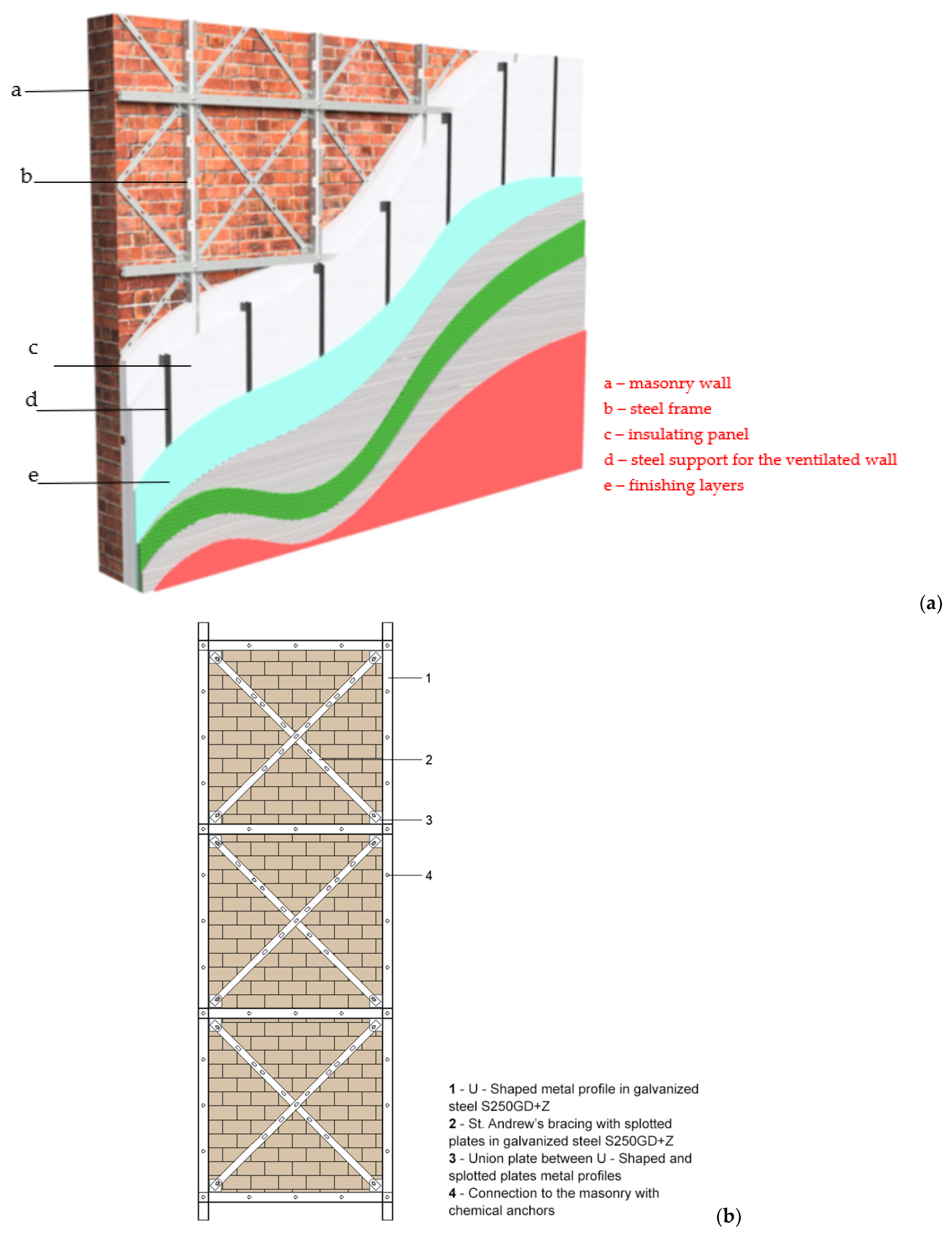
16], is composed of an exoskeleton made of cold formed steel (CFS) profiles joined with diagonal bracings in a St. Andrew’s cross configuration. The steel used for all the elements of the seismic coat is of the galvanized type, which is very useful to prevent the corrosion process, since the coat is applied outside the building facades. The used steel is of the type S250GD+Z, which has a yield strength equal to 250 MPa and a failure strength equal to 330 MPa. The CFS members are arranged in vertical and horizontal directions to form frame modules which are filled with thermal insulating panels. The entire system is completed with an external coating made up of a thin reinforced cement sheet.
In this envelope system, the CFS base frame provided with X-bracing system is intended to absorb the seismic actions, while the insulating panel is used to ensure less heat/cold dispersion from the indoor environment. In this way, the system allows an improvement of both seismic and energetic performances of existing buildings.
The application of the Resisto 5.9 system is aimed at the seismic and energy retrofitting/upgrading of a building, in order to fall within the scope of global interventions according to § 8.4.2 and § 8.4.3 of the Italian technical code NTC 2018 [
17,
18], if it is connected to the structural foundations. Conversely, it can also act as a local intervention, if it is not connected to the foundations, and can therefore be aimed at counteracting the triggering of any local mechanisms (§ 8.4.2 of NTC 2018), such as the overturning of masonry walls or infill walls out of their own plane.
The patented Resisto 5.9 system thus responds to the requests for performance required for the consolidation of masonry structures defined by current technical code.
Specifically, the Resisto 5.9 system is composed by a frame made up of galvanized steel profiles having a U–shape with dimensions of 80 mm × 60 mm × 3 mm. They are obtained from laser cutting and subsequent cold bending. These profiles, arranged horizontally and vertically with a fixed inter-axis usually of 106 cm, determine the formation of modules in which bracing diagonals, made of steel sheets with slotted holes, are inserted. A representation of the Resisto 5.9 system applied to a masonry wall together with its basic components is illustrated in
Figure 1.
The CFS elements are placed in adhesion to the masonry by means of non-penetrating chemical anchors, as shown in
Figure 2, with injection of resin into holes of appropriate diameter and length following each other with a regular pitch.
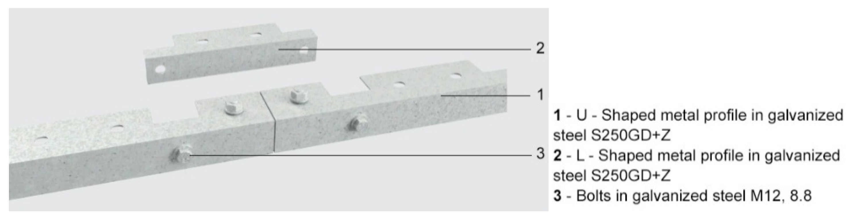
Each U–shaped profile is connected to the adjacent one to guarantee the continuity of the reinforcement via galvanized steel plates and class 8.8 bolts (
Figure 3).
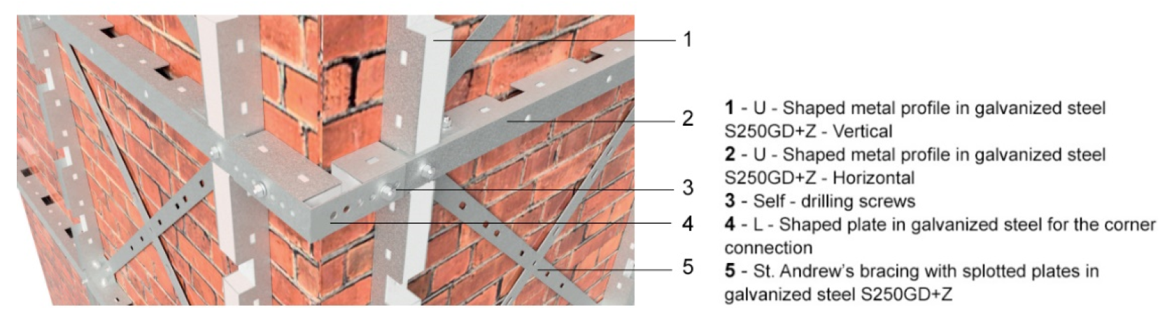
With regards to corner connections, they are made of L–shaped elements, always realized with galvanized steel, of variable length and with self-drilling screws (
Figure 4).
In general, the frame modules should be placed at least 15–20 cm away from the edge of the building to allow for the realization of these connection systems.
The system is manufactured based on a precise survey of the building made with the laser scanner technique; during the mounting phase, the various profiles need only be assembled together and connected to the structure. This allows a significant reduction of working time in the construction site, which allows consistent cost reduction.
The Resisto 5.9 envelope system, in addition to the advantages in terms of both reduced assembly time and costs, supports the so-called box effect of the building improving connections between orthogonal walls, avoiding local mechanisms such as the overturning phenomena. Finally, it provides an effective absorption of non-contrasted horizontal trusses and a better distribution of the seismic actions among masonry piers.
3. Application to the Case Study
3.1. Geometry and Material
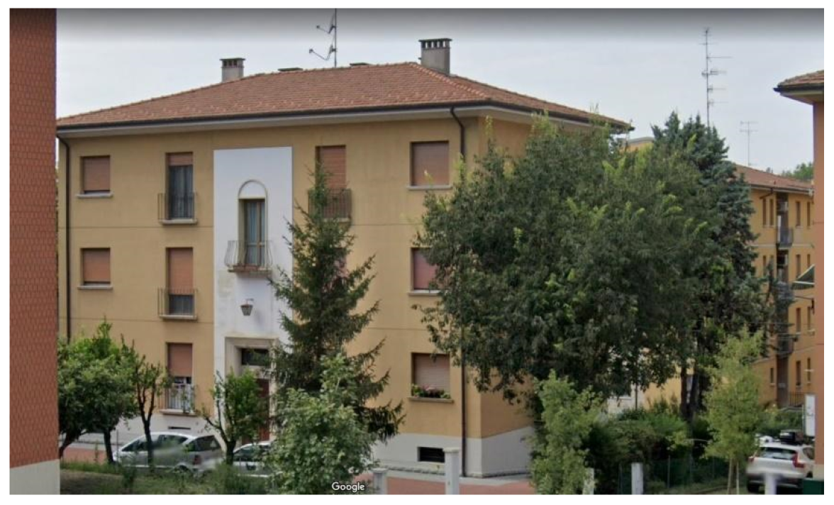
The case study under investigation is a building in an isolated position in Casalecchio di Reno, a small town on the outskirts of Bologna, in the Emilia–Romagna region of Italy.
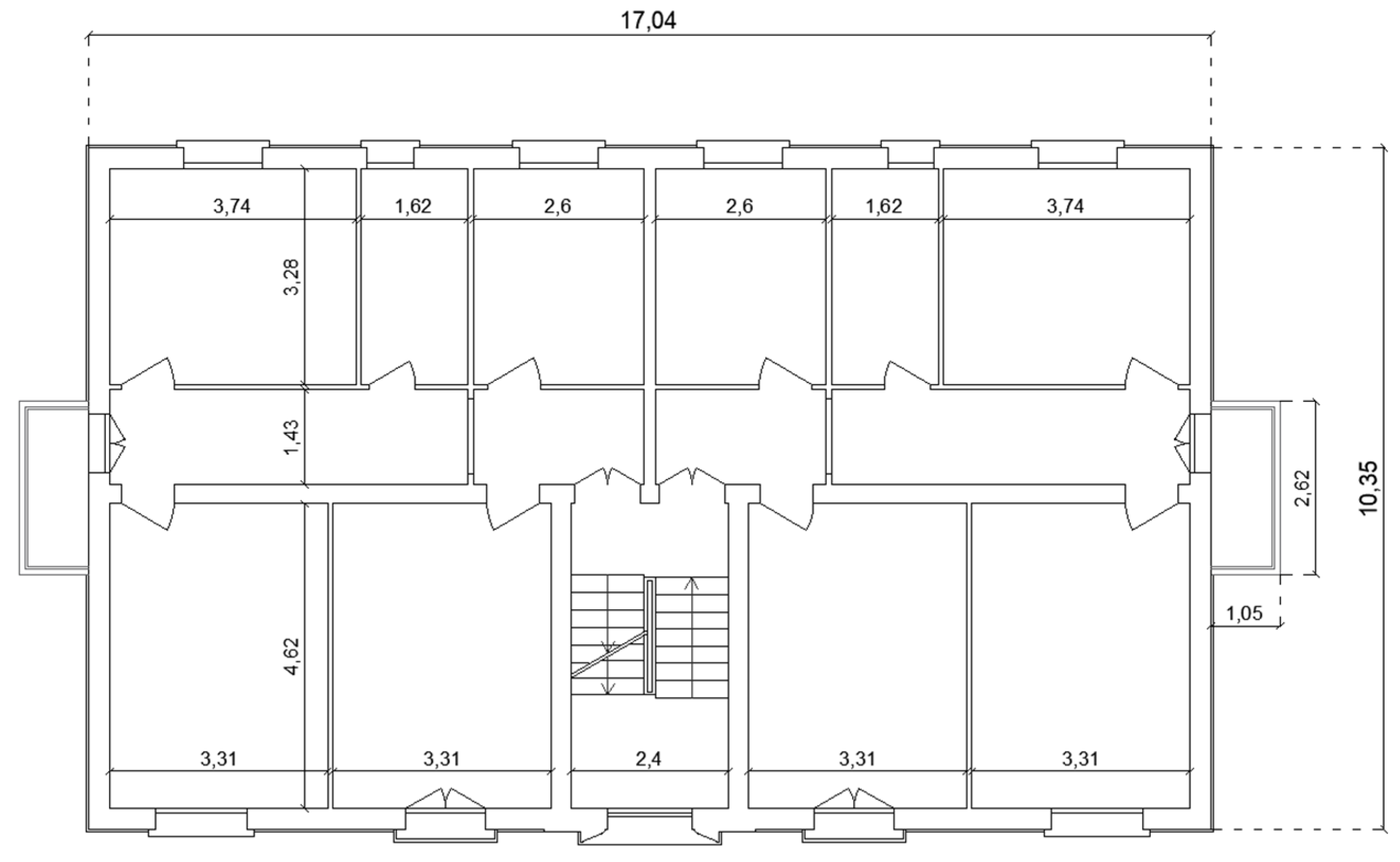
It was erected in the 1950s with a brick masonry structure typical of Northern Italy. The building is of three levels above ground, and it also has a basement. In
Figure 5, a standard plan layout of the building under study is depicted.
While the external load-bearing masonry structure is made of solid bricks and mortar, giving rise to walls with a thickness of about 30 cm, the intermediate horizontal floors are realized with SAP-type slabs of different thicknesses at various levels (14 cm in the basement and 16 cm at other floors). The SAP floor, typical of the ‘50s, is a semi-prefabricated slab consisting of prefabricated bricks and reinforced concrete joists. The reinforcement bars, of smooth type and with reduced diameter, are placed inside special grooves of the bricks and sealed with mortar [
19]. The roof structure is made of timber beams covered by a layer of tiles.
Figure 6 shows an external view of the building obtained from Google Maps–Street View.
The degradation state of the structures was acquired not only by means of visual and photographic reliefs, but also thanks to in-situ and laboratory investigations. The set of tests performed allowed the Knowledge Level 2 (KL2) to be obtained (from among the three knowledge levels considered by the current Italian technical code NTC 2018), which corresponds to a confidence factor, used for the calculation of design strengths, of FC = 1.20.
From the single flat-jack test, the average working stress of masonry was determined to be about 1.27 MPa. On the other hand, the double flat-jack test obtained a masonry collapse resistance of 2.96 N/mm2. Ultrasonic investigations supplied the average elastic modulus of the masonry, which assumed the value of 1310 N/mm2. Moreover, from penetrometric tests on mortar, its average resistance was determined to equal 2.52 Mpa.
Table 1 summarizes the mechanical characteristics of the masonry structure.
For the foundations, investigations were carried out with mechanical tools in order to determine the depth of the laying surface, which stands at about −1.50 m from the ground floor. The same test also revealed the foundation materials, which are heterogeneous pebbles in a very modest binder matrix.
The same foundations, in past years, due to settlements, produced diagonal cracks in some ground masonry walls, necessitating consolidation interventions of the soil to be carried out with expanding resins.
3.2. Seismic Analyses on the Unreinforced Building
For the vulnerability analysis of the structure before and after the application of both the seismic energy coat system and other seismic interventions, the TreMuri software (version 13, S.T.A.DATA company, Turin, Italy) was used.
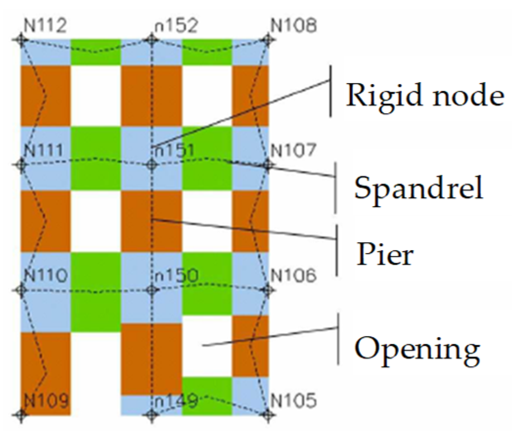
It is a calculation program allowing for linear and non-linear static analyses to assess the degree of vulnerability of both new and existing structures made of either masonry or mixed masonry-RC structures. TreMuri is based on the “Frame by Macro Element” (FME) method, where the walls are schematized with “macro-elements”, i.e., portions of masonry having a defined behaviour. They in turn are subdivided into elementary components, namely masonry piers, spandrels and rigid nodes. As shown in
Figure 7, masonry piers (in brown) represent the vertical part of masonry next to the openings, the spandrels (in green) correspond to the portions above and below the openings, and rigid nodes (in cyan) are those masonry parts connecting piers and spandrels which remained undamaged by seismic events. Therefore, they can be considered infinitely rigid compared to the other elements and so are modelled with elements of infinite stiffness.
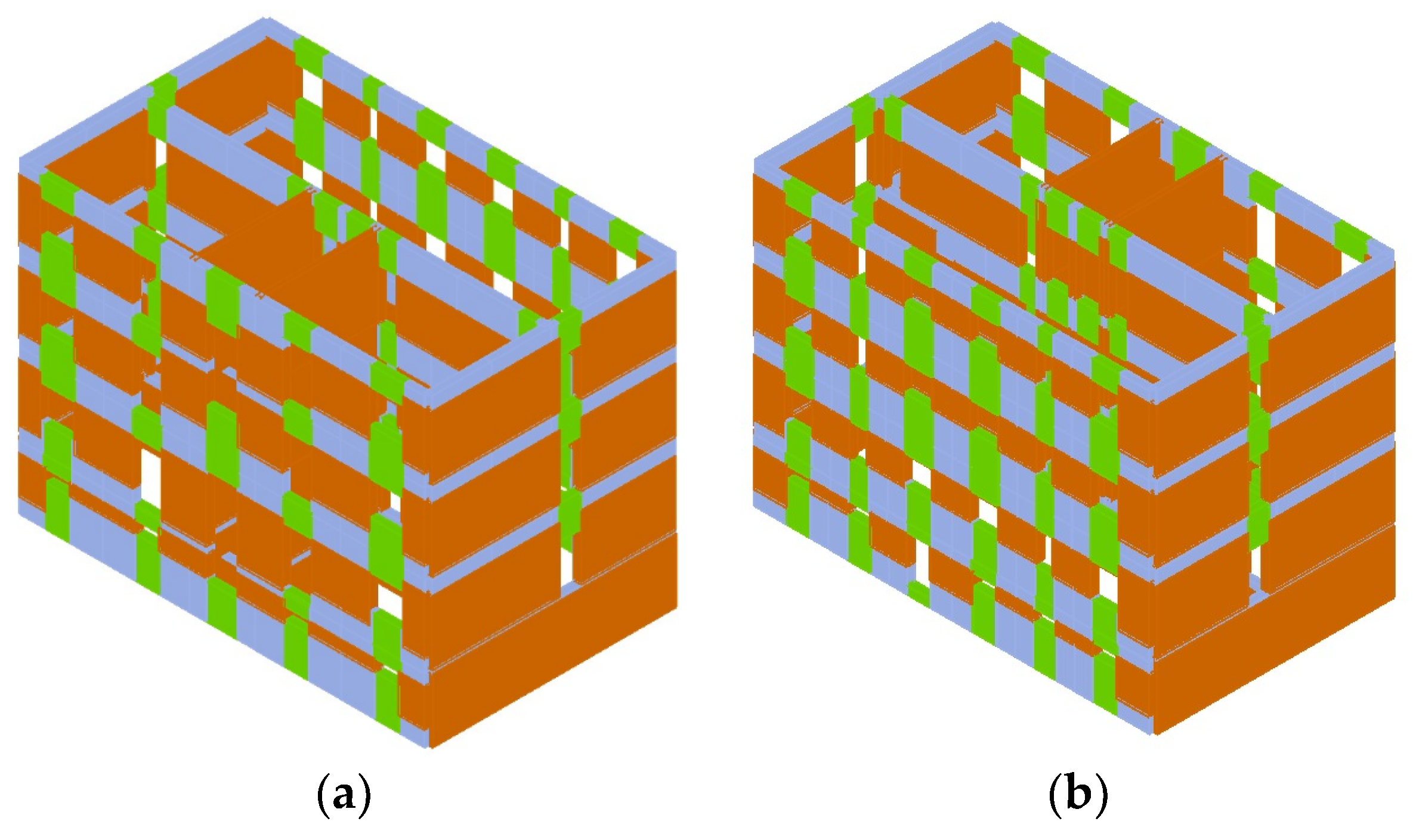
Figure 8 depicts the discretization of the case study building structure into macro–elements.
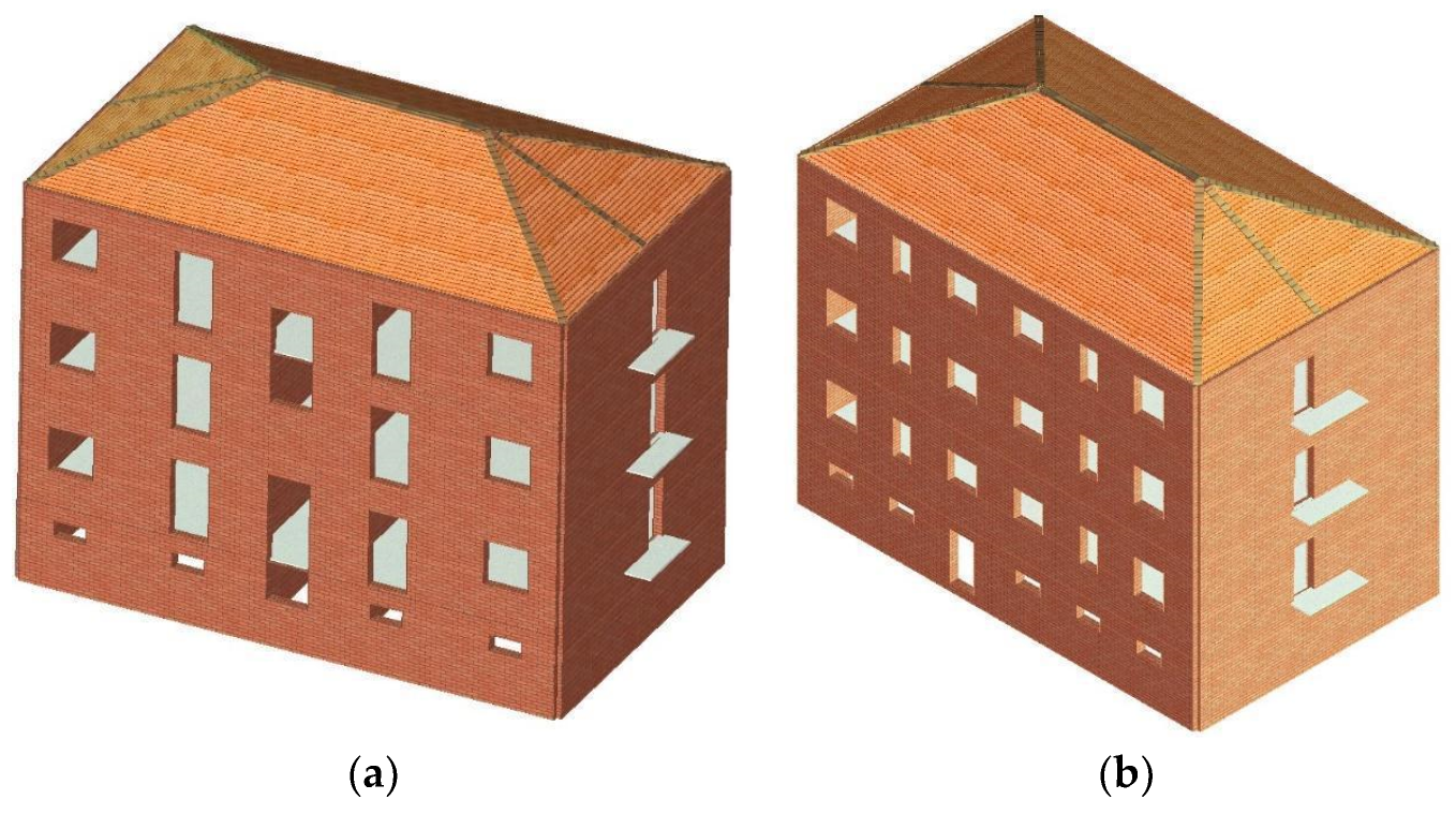
Indeed, in
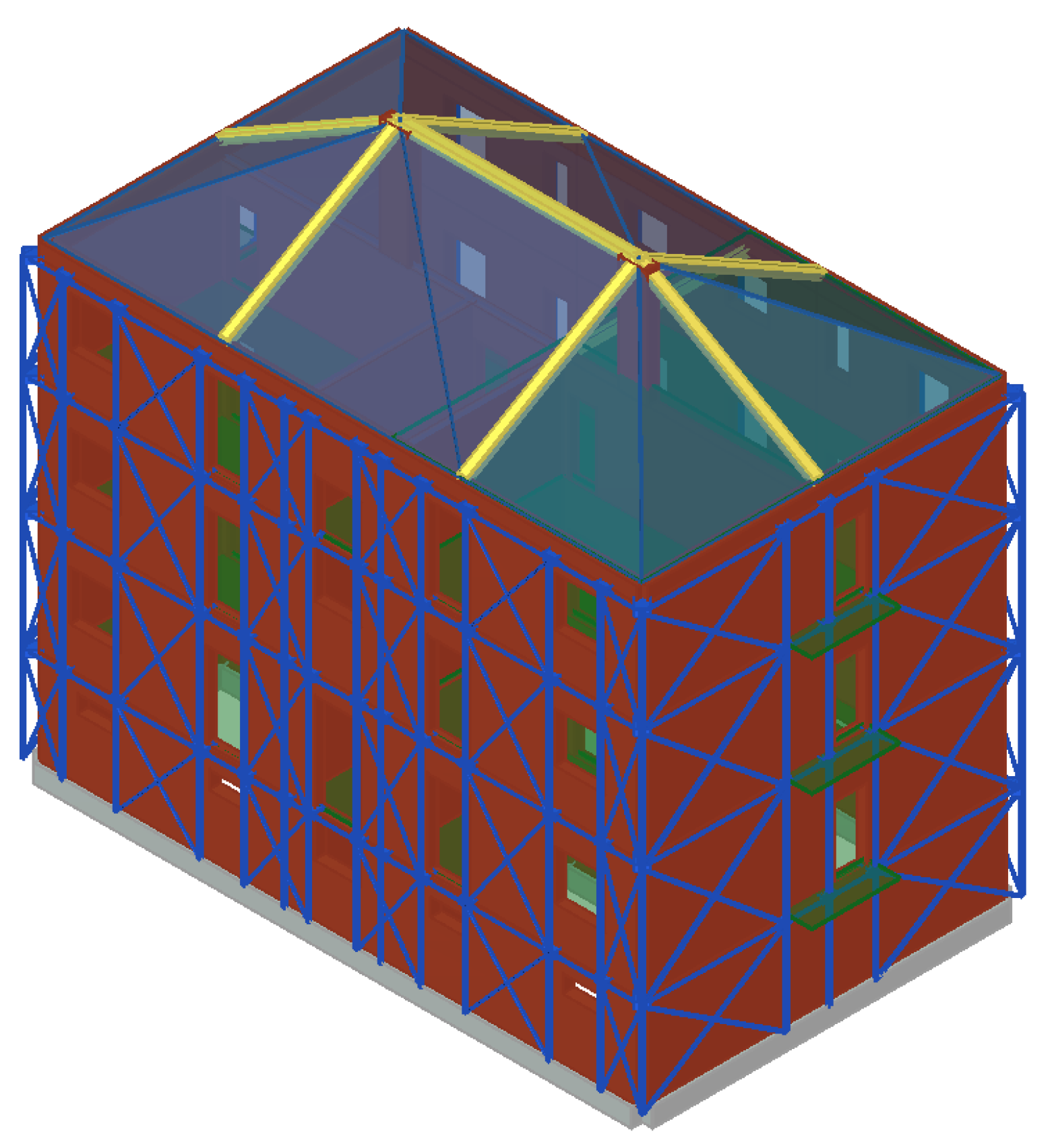
Figure 9 the three–dimensional model of the building structure obtained using the TreMuri software is illustrated.
In the first analysis phase, aimed at performing a subsequent non-linear static analysis, a linear dynamic analysis with reference to the first thirty modal shapes of the building is performed, as reported in
Table 2.
Once the modal analysis is performed, the pushover analyses are carried out on the structure considering two different distributions of forces: one proportional to the structural masses and the other one (multi-modal) based on the number of modes activating at least 85% of the participating mass of the structure. The latter is proportional to the product of the masses for the deformed shapes corresponding to the vibration modes of the structure, also considering an accidental eccentricity between the centre of mass and the centre of stiffness of each horizontal floor due to the spatial variability of the seismic motion, as well as the two possible directions of the seismic actions in each direction of analysis (X and Y).
The checks required, carried out for the various limit states (near-collapse NC, life safety LS, damage D and operational O), consist in the comparison between the capacity displacement, identified in the base shear-top displacement capacity curve, and the demand displacement provided by the technical code. The analyses are performed under displacement control, monitoring a building top point (the so-called control node). The software calculates the distribution of forces generating the required displacement value and continues until the decay of the shear reaches 20% of its peak value. In this way it is possible to derive the maximum displacement value at the base of the building generated by that distribution of forces.
In order to identify the most severe seismic load condition, all 24 analysis cases provided by the current code were carried out, differentiated by type of load, direction of the earthquake and any accidental eccentricities.
Table 3 shows the results of the pushover analyses carried out on the structure with reference to the results corresponding to the worst verification. In particular, at the Life Safety (LS) limit state, the worst analyses are No. 2 in the X-direction, with α = 0.510, and No. 22 in the Y-direction, with a value of α equal to 0.780.
Therefore, based on pushover analyses results, the building is not able to withstand the design earthquake in both load directions and it is more vulnerable in the X-direction.
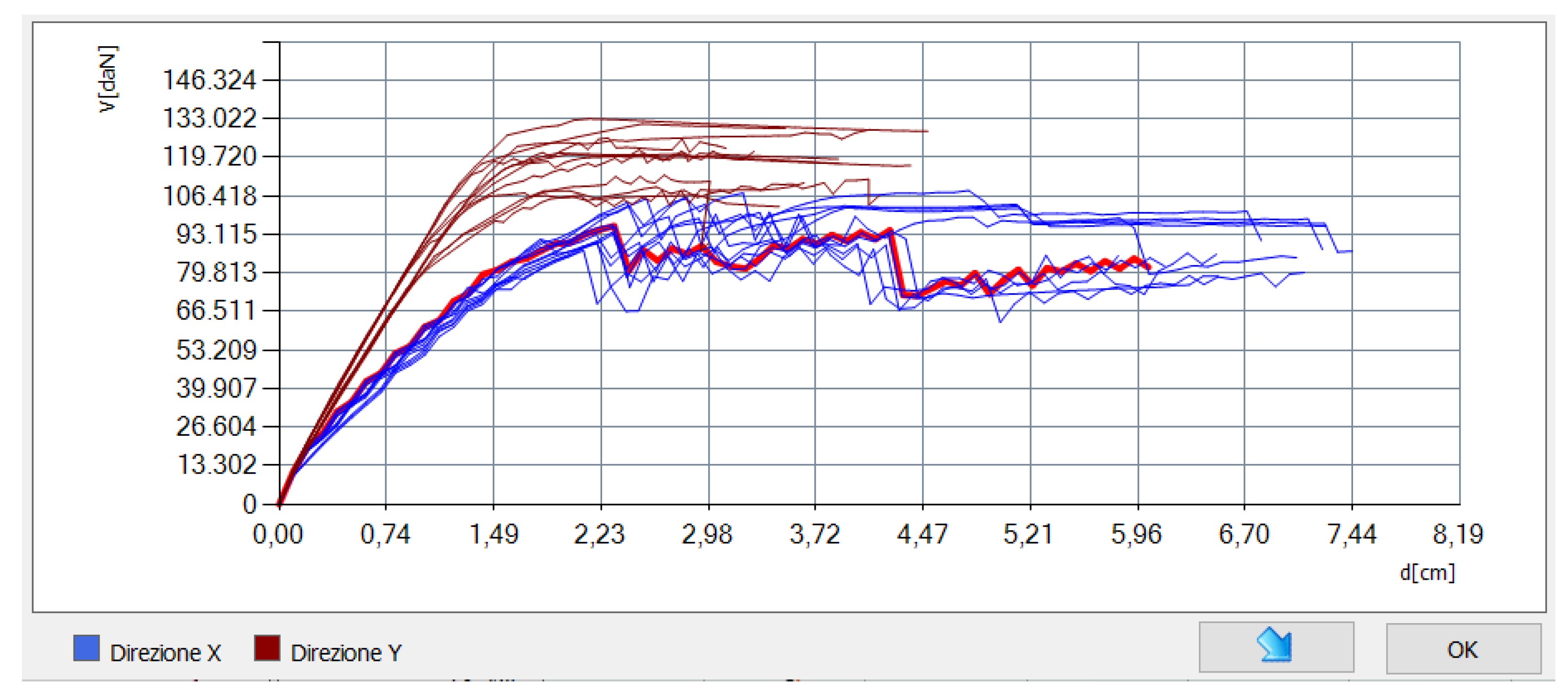
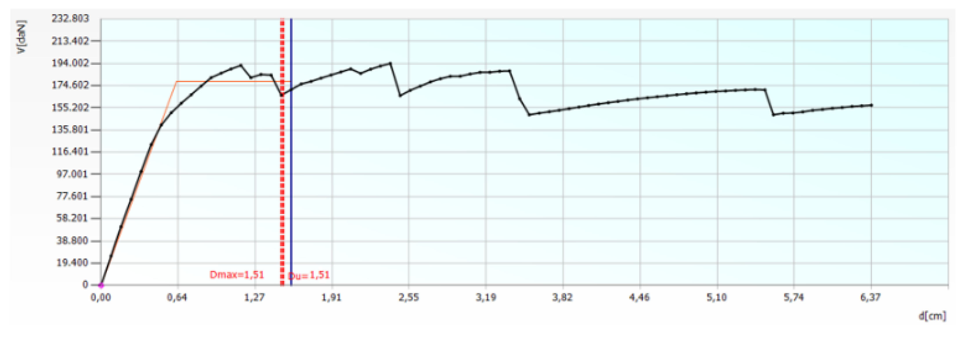
Figure 10 shows the curves for all load cases considered.
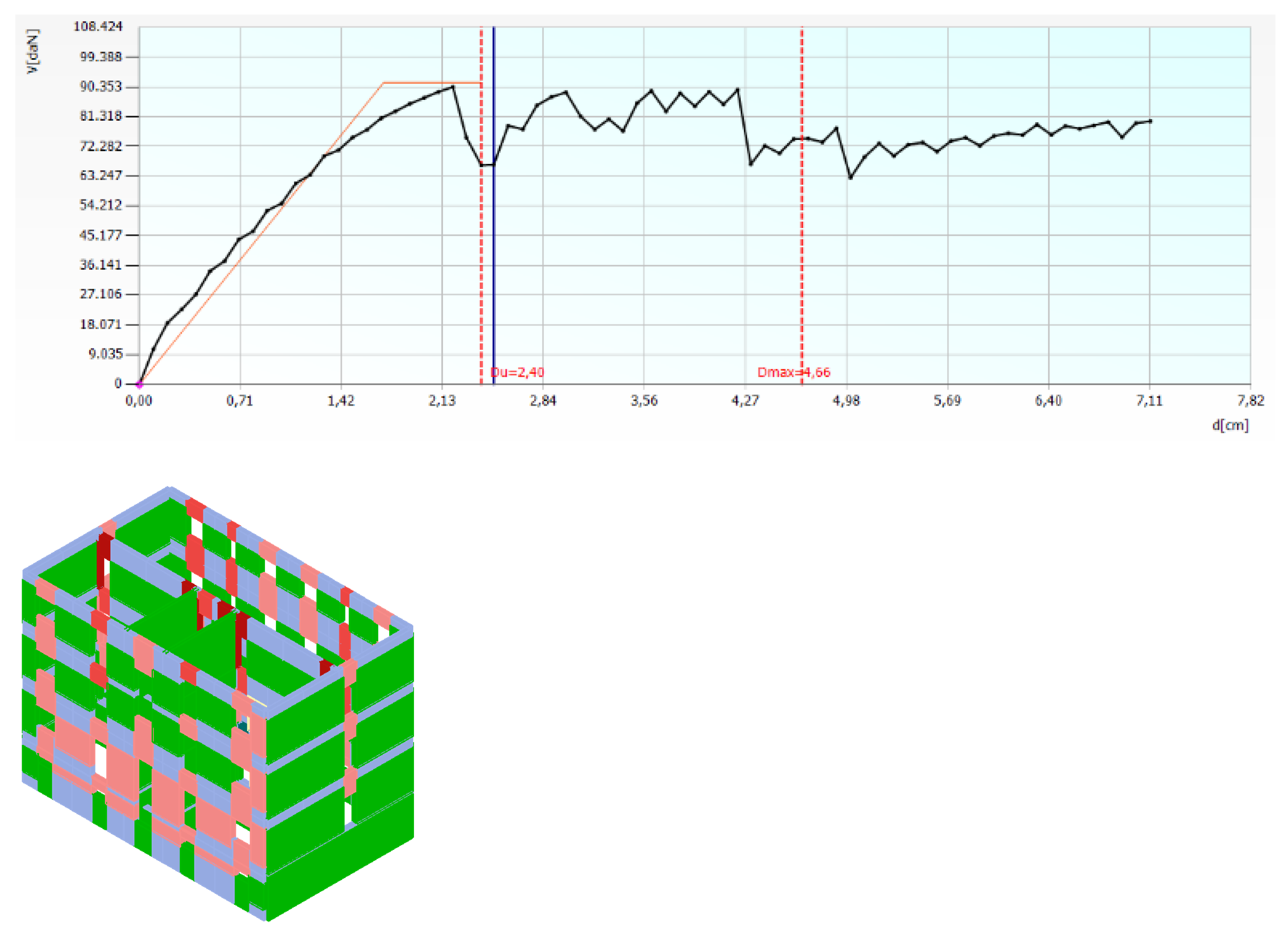
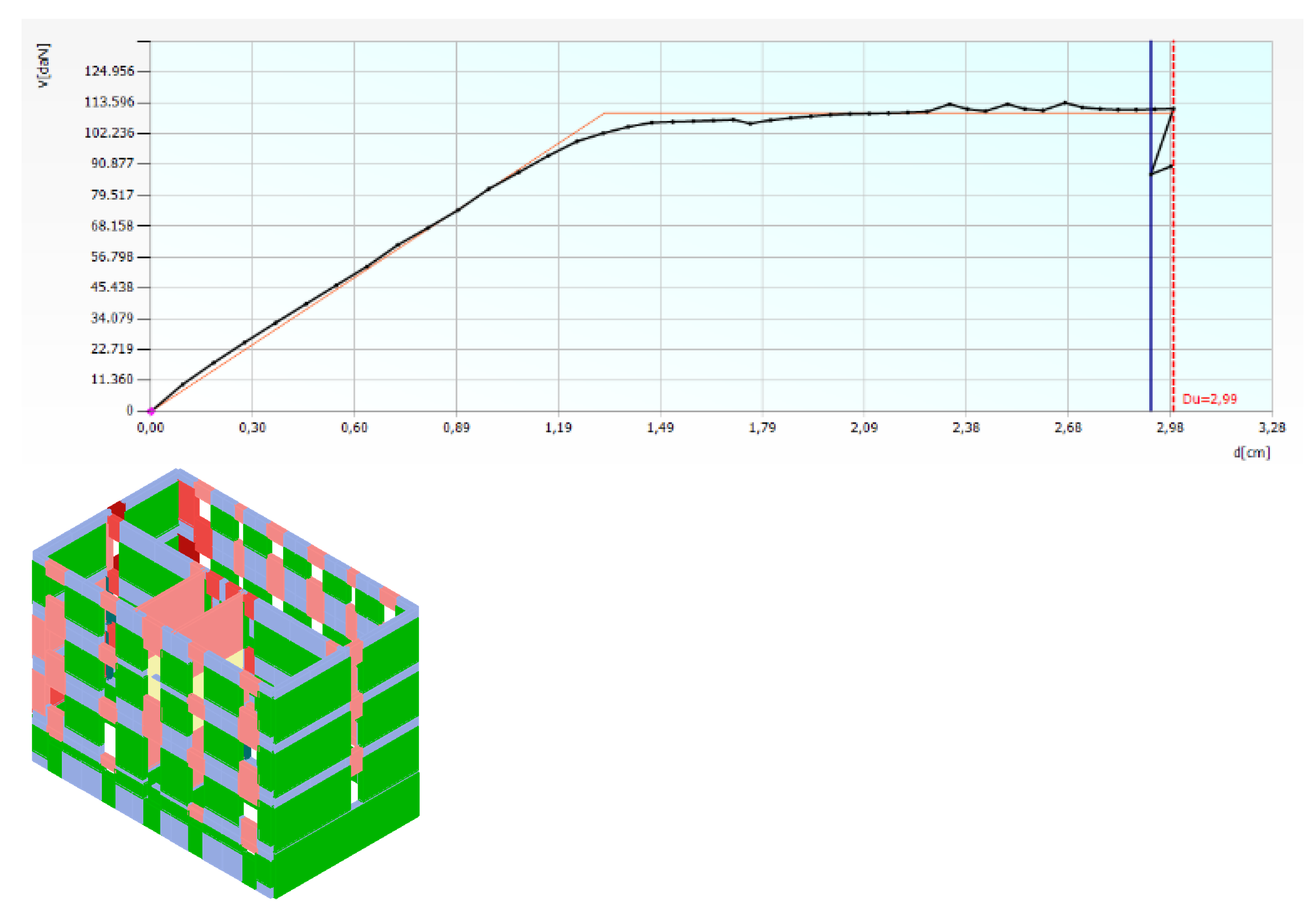
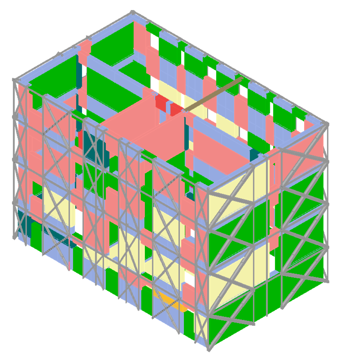
The results of the analyses in terms of both pushover curve and collapse mechanisms with reference to the X-direction and the Y-direction are shown in
Figure 11 and
Figure 12, respectively.
From the previous images, it can be deduced that in both directions the building presents excursions in the plastic field due to both compression-bending and tensile actions (pink and yellow macro-elements, respectively) and collapse phenomena due to compression-bending (red macro-elements).
Since the building shows a deficient seismic behaviour, different interventions aimed at its seismic retrofit have been designed.
3.3. Design of the Seismic Energy Envelope
In order to improve the seismic behaviour of the studied building, the application of the Resisto 5.9 seismic coat was foreseen. The envelope system was applied to all building facades, including the vertical parts between the openings which, for the sake of safety, were considered in the sizing process of the coat, whose seismic-resistant elements consist of diagonals made of steel plates.
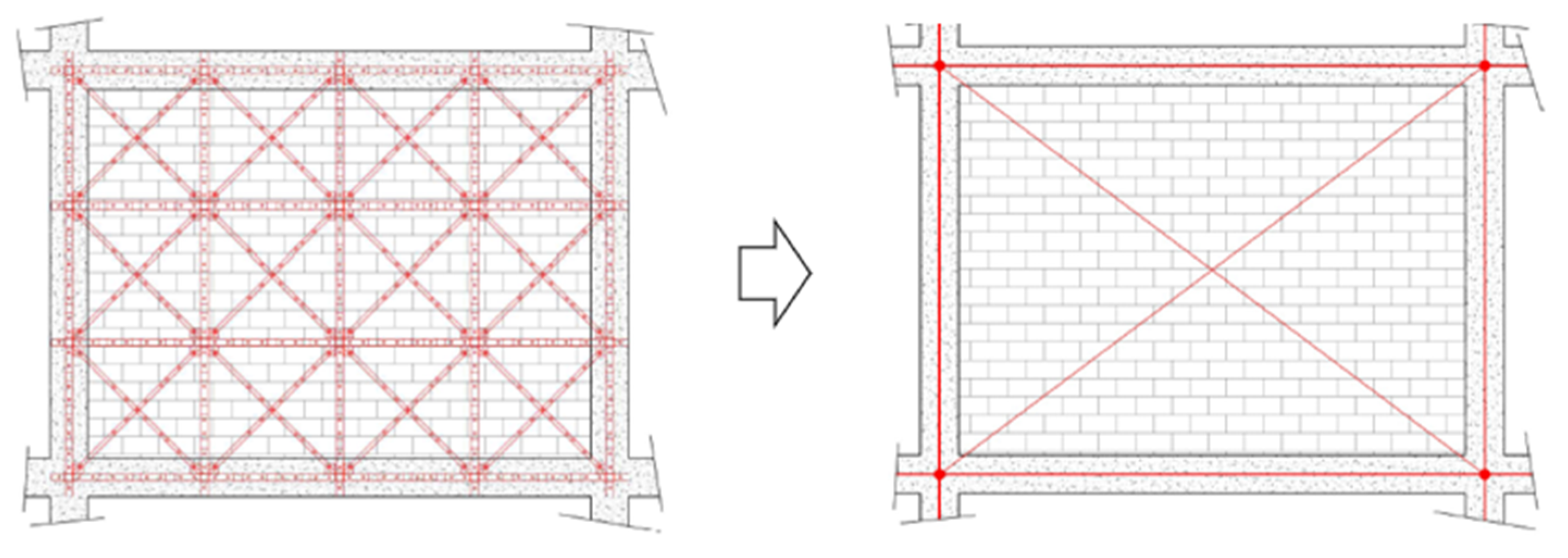
The modelling was carried out by inserting, for each masonry pier of each floor, a frame equipped with steel braces laid out in a St Andrew’s cross pattern. The bracing system has a cross-section equivalent to the contribution of all the diagonals present in the considered masonry panel area, as shown in
Figure 13.
The evaluation of the diameter of the diagonals to be included in the calculation model was made by identifying the equivalent stiffness of the diagonal with the following equation:
where K
i is the stiffness of each diagonal placed on the masonry pier under examination, obtained as EA/L; E, A and L being the Young modulus, the cross-section area and the length, respectively, of the diagonal.
Therefore, starting from the equivalent stiffness it was possible to derive the equivalent area A
p, and then the diameter φ, of the equivalent brace element [
20,
21], by means of the formula:
where
Ep = Es is the elastic modulus of the material. In this case we have steel S250 with a value of 210,000 MPa;
lp = equivalent length, equal to b/cosα
α = arctg h/b
The above geometric parameters characterising the equivalent brace of the system are represented in
Figure 14.
In
Figure 15 there are all the façade fields (in orange) used for calculation of the Resisto 5.9 system and the corresponding equivalent diagonals (in red).
The Resisto 5.9 coat was applied continuously on the entire façades with a variable distance between the uprights and crosspieces, which was assumed in any case not to exceed 1060 mm.
The placement of envelope profiles on the facades is shown in
Figure 16, which highlights the system continuity necessary not only for a better seismic response, but also for the installation of the insulation panels needed to reduce the thermal dispersion and to avoid thermal bridges.
3.4. Other Seismic Interventions
In addition to the Resisto 5.9 seismic energy coat system, other interventions have been designed for the seismic retrofit of the structure. Specifically, they mainly consist of both the replacement of the roof structure with a new one and the reinforcement of the foundation structure.
3.4.1. Replacement of the Roof
The existing roof is made of a wooden structure with four inclined pitches. The intervention involves its replacement with a new structure made of GL32h laminated timber maintaining the same original geometry. Fistly, following the demolition of the existing roof beams, the damaged areas of the existing masonry walls are restored through the “scuci and cuci” technique. Later on, the erection of the new beams is foreseen. In particular, three different sections are used: 20 × 24 cm for the ridge beam, 16 × 24 cm for the main beams and 8 × 10 cm for the secondary beams.
Figure 17 shows all the designed section.
3.4.2. Foundations
The existing foundations, placed at a depth of about −1.35 m from the ground floor, are made of heterometric and heterogeneous pebbles in a very modest matrix. They have a height of about 50 cm and a width of 60 cm. In the past, due to settlement, ground story walls were cracked and the soil was consolidated with expanding resins, which effectively stopped the crack pattern.
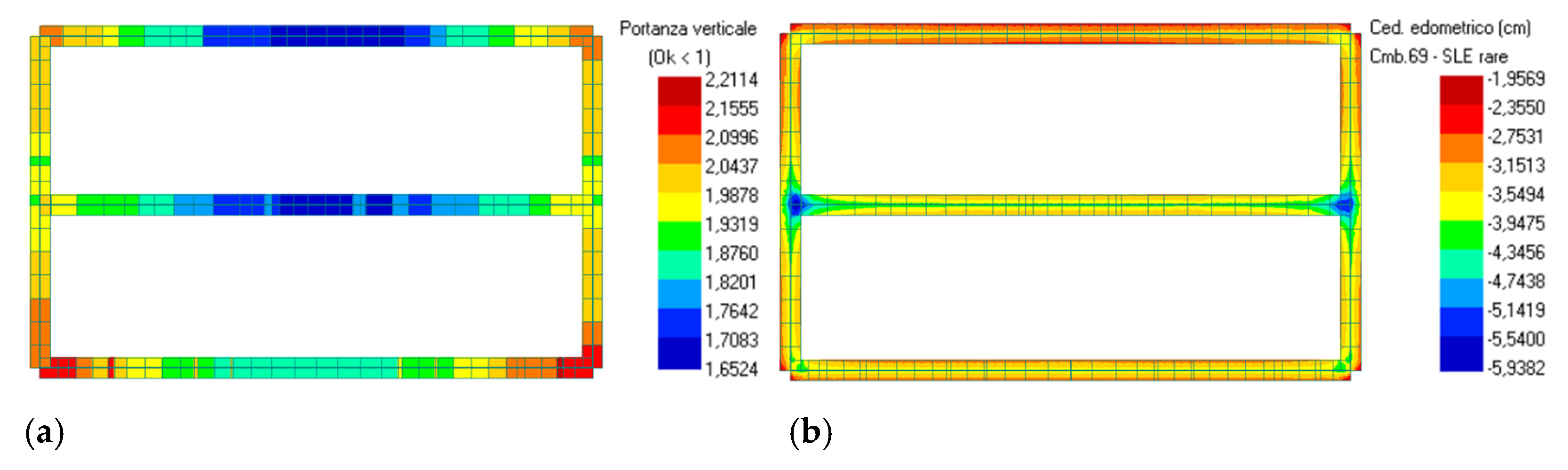
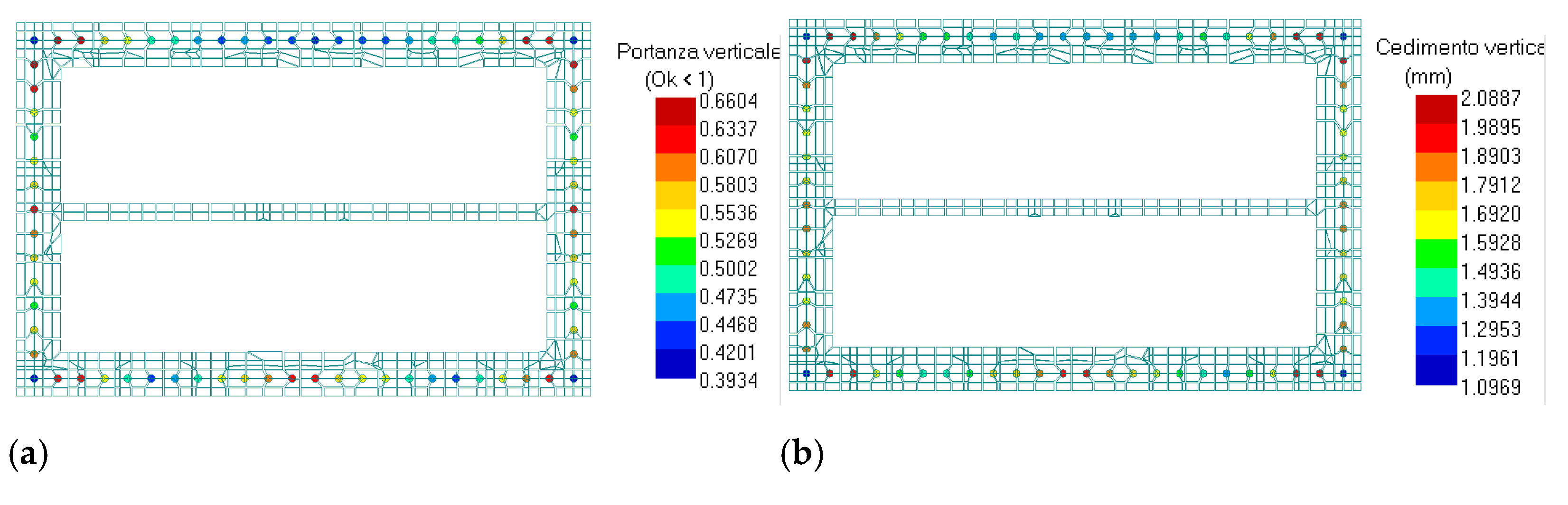
However, the added coating system has required the verification of the foundation system to transfer safely to the soil the absorbed seismic actions. This check phase has shown that from the ground-foundation interaction, in terms of bearing capacity and subsidence, a deficient behaviour of the foundations was observed. Therefore, to guarantee a proper and safe transferring of seismic loads to the base, an enlargement of foundations was made using RC beams 90 cm in width and 50 cm in depth, connected to the original masonry foundation through steel bars and chemical anchors. These beams act as crowning beams for a series of micropiles of a diameter of 25 cm and a length of 12 m, arranged with a pitch of 80 cm along the entire perimeter of the building.
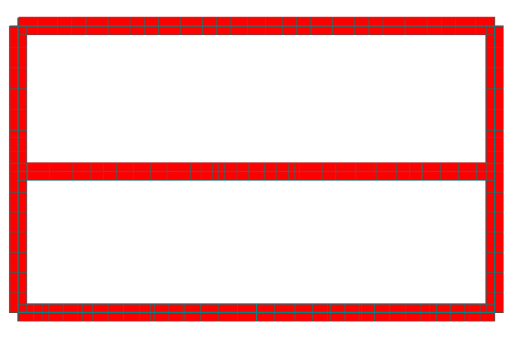
The design of this intervention was carried out with the finite element analysis calculation software Pro_Sap. In
Figure 18 and
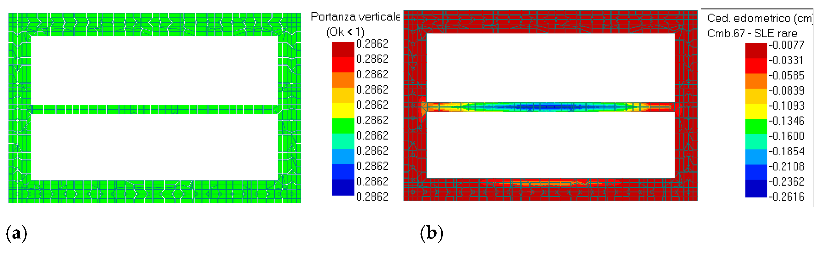
Figure 19 the synthetic verification, together with the calculation of the bearing capacity and the subsidence check of the foundation FEM model of the original structure, is shown. The same results are depicted in
Figure 20 and
Figure 21 for the micropiles and beams, respectively, of the reinforced foundation structure.
The checks show that the load-bearing values of the new foundations, with reference to the worst load combinations, are all below the unit. Thus, the reinforced foundation with new RC beams above micropiles connected to the masonry beams is able to withstand safely the vertical and seismic actions transmitted by the structure.
4. Seismic Analyses on the Retrofitted Structure
As in the investigation on the bare building, the TreMuri software is used for vulnerability analysis of the retrofitted numerical model of the building, based on the design of interventions previously described. In
Figure 22 it is possible to observe the steel frame with the equivalent diagonals representative of the Resisto 5.9 system installed on the building facades.
Also in this case, in the first phase, the dynamic analyses referred to the first thirty modal shapes of the structure was performed, as shown in
Table 4.
Subsequently, the pushover analyses on the building after interventions were carried out based on the 24 load combinations already used for the bare building. In
Table 5 the worst results related to the two analysis directions are highlighted in green.
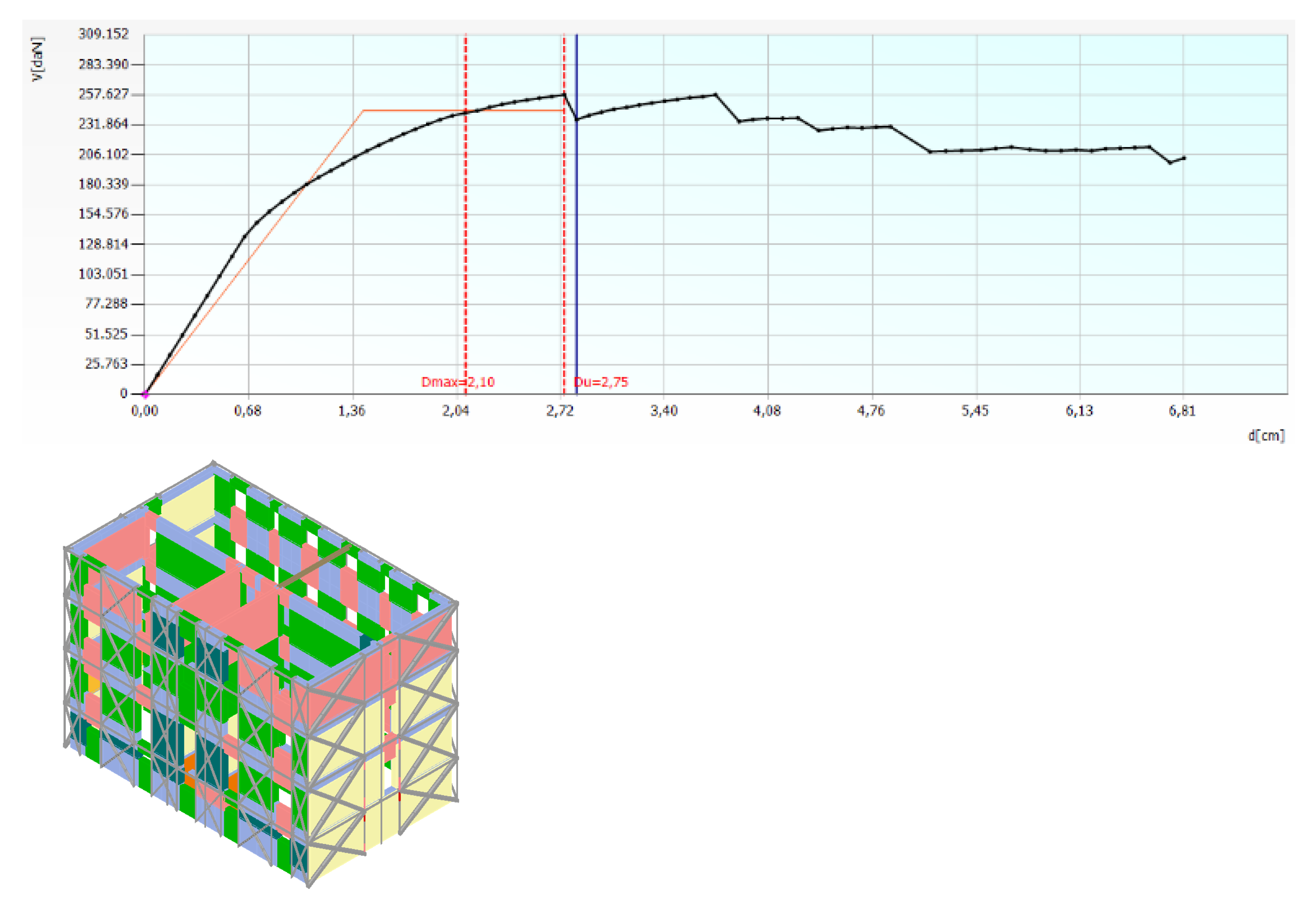
In
Figure 23 and
Figure 24 the analysis results in the X- and Y-directions in terms of pushover curves and damages on the three-dimensional model of the building are illustrated, respectively.
From analysis results, however, it appears that all checks referred to each considered limit state are satisfied. This means that the global seismic upgrading of the building under examination was attained.
5. Conclusions
The current work dealt with the seismic-energy upgrading of a masonry building in Casalecchio di Reno, a small town in the outskirt of Bologna, in Northern Italy.
The solution herein saw the application of the CFS Resisto 5.9 system, developed by Progetto Sisma S.r.l. company, installed on the building facades to reduce the thermal dispersions of the building and to increase its seismic capacity thanks to confinement actions on the building facades, to avoid local collapse-overturning mechanisms, and to absorb in-plane seismic forces to improve the in-plane resistance of the structure. Other than this system, two further interventions, namely the replacement of the old wooden roof with a new laminated timber one and the reinforcement of the masonry foundation with a composite RC beams-micropiles system, were planned to improve the seismic performances of the studied building.
The linear dynamic analysis proved that the performed interventions are capable of regularizing the building modal behaviour, with the first two modes of translational type (first along the transverse direction and second following the longitudinal direction) and the third mode exhibiting torsion behaviour. In particular, when Resisto 5.9 was used as the retrofit system, the participating mass of the second mode in the longitudinal direction increased by about 40% in comparison to that of the bare building.
Furthermore, the pushover analysis results on the building equipped with the seismic coat and provided with both the new roof and the reinforced foundation showed seismic safety factors greater than unit, so attaining the complete seismic retrofit. In particular, the seismic safety factor of the bare building assumed values of 0.51 in the X-direction and 0.78 in the Y-direction, while it reached values equal to 1.049 in the X-direction and 1.274 in the Y-direction after execution of the above-mentioned seismic interventions.
As a whole, the achieved results testified to the effectiveness of the Resisto 5.9 system in significantly improving the seismic performances, other than the energy ones, of the tested masonry building. However, the achieved results cannot be generalized but should be intended only for the case study examined. For this reason, further advancements of the study will deal with the development of several case studies to provide more proof of the seismic and energy benefits derived from applying the proposed coating system to existing masonry buildings.


 ,
, 


