Article

Optimization of the Stacking Plans for Precast Concrete Slab Based on Assembly Sequence

School of Civil Engineering, Architecture and Environment, Hubei University of Technology, Wuhan 430070, China
*
Author to whom correspondence should be addressed.
Buildings 2022, 12(10), 1538; https://doi.org/10.3390/buildings12101538
Submission received: 25 August 2022 / Revised: 18 September 2022 / Accepted: 21 September 2022 / Published: 26 September 2022

Abstract

:
Precast concrete (PC) slabs are widely used in the assembly of concrete residential buildings. The PC slabs are manufactured at the factory and then arranged in stacks for transport to the construction site for assembly. Currently, optimization of the stacking plans for PC slabs focuses on yard-space utilization and transportation efficiency and rarely considers the assembly sequence; secondary sequencing of prefabricated elements is required during construction to meet the lifting scheme, which leads to increased construction preparation time and risk of worker injury. To enable stacking crews to generate stacking plans rapidly and systematically to improve the on-site lifting efficiency of the components, this paper proposes a storage-location allocation model with two objectives: reduce secondary-sorting workload and increase stacking stability for PC slabs. At the same time, it must match the characteristics of the problem. To prevent the solution from falling into the local optimum during the evolution of the particle swarm optimization algorithm, we introduce an elitist learning strategy, which can improve the solutions when the group converges. Finally, we verify our allocation model and optimization algorithm through example simulations. The simulation results show that, compared with the traditional method, the stacking plans generated by this method have a lower secondary-sorting workload and higher stacking stability when using the same number of storage racks.

1. Introduction

Assembled construction has gained momentum in the building construction industry in recent years. With this technology, building products can be constructed and delivered by assembling prefabricated concrete components from factories. Compared to the traditional on-site concrete casting method, this construction technology requires fewer on-site operations and human resources, less environmental pollution, a shorter construction period, and higher construction quality [1,2]. However, the construction of precast concrete structures is a relatively complex process involving a series of operations such as design, production, storage, transportation, lifting, and installation of the components [3,4]. In this process, storage is a crucial operation—especially for projects located in urban centers, where the temporary storage space for precast components is limited—so most of the components are directly lifted and installed from the component transporters. It is then that the problem of “reordering” arises in the process. “Reordering” here refers to the operation of removing interfering components in a pile of prefabricated components in order to access the desired component to be installed according to the construction sequence of components [5]. This operation is common in the storage of precast horizontal elements. Taking precast concrete (PC) slabs as an example, the factory usually produces the PC slabs before the delivery of the remaining elements. The produced PC slabs are then safely and quickly placed on the storage racks according to the requirements of the project and floor classification, before being safely and in a timely manner transported to the construction site. Because PC slabs are loaded, delivered, and unloaded in stacks, and the sequence in which slabs are stacked is maintained until each of them is moved to the installation area and installed, any misalignment of the PC slabs during the stacking process can lead to secondary-sorting problems, thus causing unnecessary time waste with the finding and secondary handling of slabs, further causing undesirable delays in the construction schedule [6,7]. Therefore, it is of great significance for component manufacturers to develop a reasonable stacking plan to achieve the automatic allocation of prefabricated component storage locations in order to effectively improve the utilization of storage space in the yard and the efficiency of component lifting and installation.
Existing construction management studies have proposed relevant models, such as optimal parking locations for component transport vehicles upon arrival to minimize worker movement distances or lifting distances [8,9]. However, such studies only focus on the activities that take place on-site after the delivery of prefabricated components and do not address the stacking plans that are generated for these components once they are off-line at the factory. In the shipping vessel industry, the high degree of standardization of modern containers allows them to be efficiently circulated and stacked in any port in the world [10,11,12], while in the steel industry, optimal stack-selection decisions for slabs play an important role in buffering slabs from the continuous casting process, coordinating the production rhythm of the processes, and improving the distribution rate of slabs out of storage [13,14,15,16]. Although containers, slabs, and PC slabs have similarities in the storage and transportation process, the method and calculation model can only develop a stacking plan for them. In the research on the stacking of precast components for panelized-structure buildings, researchers have defined two metrics to measure the number of readjustments of the component-stacking plan and panel stability, allowing stacking crews to assess the reasonableness of panel stacking, but they have not pointed to specific solutions [5]. In addition, with the lighter weight, different and less-demanding stacking rules for wall panels in panelized structures, and the large differences in stacking and transport of the PC slabs used in large numbers in Chinese assembly buildings, the results of research into the application of panelized structures to wall-panel storage methods are not fully applicable to PC slabs. However, at present, the stacking plan of horizontal components such as PC slabs in the assembly building industry has not been customized and optimized. In order to further strengthen the link between theoretical research and practical applications, and to fill the research gap in this field, there is an urgent need for research into the practical application of PC slab storage technology.
In this article, according with the characteristics of the storage methods for PC slabs, a method combining mathematical models and an optimization algorithm is introduced. The method is based on the fact that the production line adopts the optimal production-scheduling sequence, and the lifting sequence of the components is considered as a whole, in order to bring about the automatic generation of the optimal stacking plans of the PC slab. The rest of this paper is organized as follows. Section 2 introduces the current logistical process of PC slabs, the problems, and related research. Section 3 shows the optimization principle of component location assignment through a framework diagram. Section 4 provides the research methodology. Section 5 presents the algorithm for solving the optimization problem in the model and the algorithm-improvement strategy. Section 6 includes example simulations and a discussion of the results. Finally, conclusions and directions for future research are given.

2. Research Background

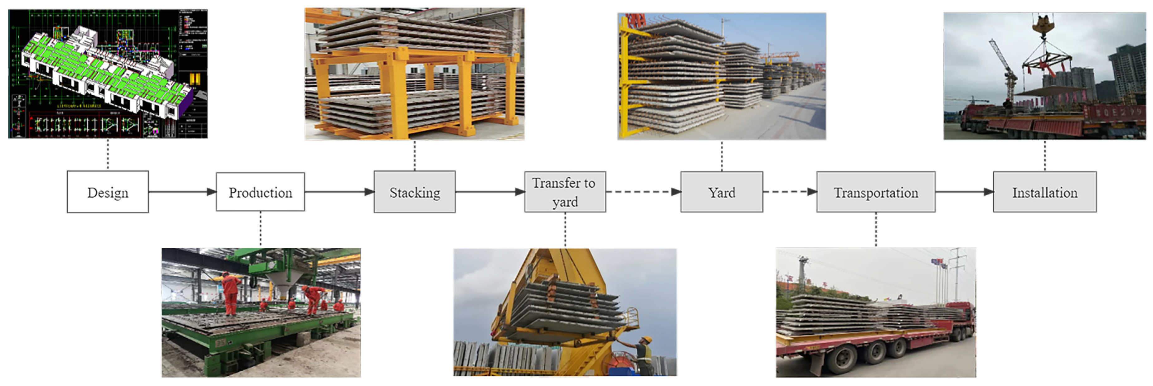
2.1. Current Logistical Process of PC Slabs

Research interviews with factory stacking crews and installation crews revealed that most prefabricated factories have adopted a more efficient storage rack for horizontal components such as PC slabs. The storage rack is simple in structure, less expensive, and can effectively increase the storage capacity of the yard. After producing PC slabs, there are four main steps: off-line stacking, yard transfer, outbound transport, and installation. In the stacking process, the workers stack the finished PC slabs that have been demolded and rolled off the assembly line onto the storage racks in the temporary stacking area in the workshop. The operator usually allocates positions according to the project’s requirements, floor information, and delivery date during the stacking process. The storage requirements for PC slabs limit each rack to a maximum of six PC slabs, and only one component can be placed on each layer. Square timber is placed between the components to prevent additional stress on the components during storage. To prevent delays in the delivery of the components, the factory usually maintains a stock level of one or two stories, so most of the finished PC slabs are transferred to a larger outdoor yard for storage by means of a whole stack. For outbound transport, the transporters park a truck at the manually recommended loading point. An operator operates the portal crane to lift all the component storage racks on the floor to be transported from the storage area to the transport truck to complete the outbound delivery. When the components arrive at the site, a crane operator lifts them directly from the transport truck to the installation position. The construction process for the PC slabs is shown in Figure 1.

2.2. Problems with Stacking of PC Slabs and Determination of Stacking Solutions

Through the investigation of several prefabricated component factories and construction sites in Wuhan, the current goals and constraints in the planning process of stacking PC slabs are determined. According to the investigation, most component factories currently use manual scheduling to assign stacking positions. The yard-scheduling stacking crews assign stacking positions for the PC slabs based on their understanding of the yard and work experience, and guide the cranes to transfer and store them. However, this manual allocation has certain limitations, such as constant changes in PC slab inventory information, and it is impossible for stacking crews to fully understand and understand in real-time; different stacking crews have different habits, which will lead to different stacking-position allocation principles, etc. Therefore, the stacker cannot fully consider the planning objectives and constraints. At the same time, the number of PC slabs processed at one time is large, and the consequences may lead to the unreasonable stacking of PC slabs. Much meaningless secondary-sorting work needs to be done before hoisting the PC slab at the construction site. According to the estimation of the on-site management personnel, the number of components that need to be readjusted in each batch accounts for about 40% of the batch of components. This meaningless secondary hoisting wastes time and greatly increases the hoisting time of the crane, thereby affecting the progress and cost of construction operations. Therefore, the on-site lifting personnel all think that the optimal stacking sequence is the most important goal of stacking, which can not only increase the available space on site but also speed up the construction progress. However, it is not always possible for stacking crews to assign PC slabs in an optimal storage order, since PC slabs vary in size; in addition, to prevent tipping, the palletizing decision can be reduced to a class of constrained A-Shaped Bin Packing Problem (ASBP) where the stacking assignments require that PC slabs of greater size or weight be placed below smaller (or lighter) PC slabs as much as possible to ensure stability and safety during storage and transport [17].
Although stacking crews are aware of the need for these constraints and use their experience in generating stacking plans to enforce them, this prevents them from generating optimal stacking plans quickly in a quantitative and accurate manner, leading to stacks that require extensive readjustment work at the construction site. Therefore, this paper formally considers these constraints and objectives in its model.

2.3. Related Research

The literature review revealed that the research literature related to the stacking sequencing problem of PC slabs in assembled buildings is relatively sparse. Yujin Lee and Kim et al. quantitatively evaluated the readjustment effort of multiple stacks in time, helping them to determine the optimal stacking position in advance. One limitation of this study is that it only uses the “number of panel moves” as the evaluation metric for stacking. The basic principle and optimization scheme for component-stack generation is not given [18]. While Lee et al. generated stacking plans for trailers with A-frames, their method cannot develop stacking plans for other types of frames or panels of different types [19]. Shechuk et al. proposed an algorithm to minimize stacking quantity, panel-material handling distance, and effort required to position and support the panels [8]. Guo proposed a mathematical model for arranging panel-unloading locations on construction sites to minimize workers’ moving distance and to distribute the tasks equally among workers [9]. However, these studies only focus on the stacking of prefabricated interior wall panels and do not address the reordering work and stacking stability problems of PC slabs.
Apart from these studies, the most closely related papers are those dealing with the optimization of slab storage in steel plants, as well as the layout planning of construction sites and the planning of construction processes. In the slab storage-optimization problem, a target stack is selected for each slab for storage to minimize the number of transfer moves in subsequent retrieval stages. Cheng and Tang proposed a scatter search algorithm for slab-stack shuffling problems [20]. Li et al. studied a similar problem of the SSP. They recommend stacks for inbound slabs [21]. However, the objective of their investigation is to satisfy existing stacking rules better. Zhang studied the slab relocation problem, where a set of slabs are to be retrieved from a set of stacks in a specific order using the fewest number of relocations [22]. However, their focus is on the selection process of slabs from stacked piles and not on actual stacking process. Peixin presents an integer linear programming model to optimize the storage of slabs, starting from the stacking process, to minimize the number of relocation moves in the subsequent retrieval phase [23]. However, their method and computational model can only make a plan for the stacking of slabs. In terms of construction site layout planning, Jang et al. propose a floor-level construction material layout to minimize repositioning construction materials, using a genetic algorithm to tackle the problem. Their method reduces material handling time, but the factor they consider is crane location [24]. PC slab stacking and stacking location are not addressed. Several other authors have studied the automatic generation of construction plans. Hu proposes a model based on geometric reasoning that reverses the disassembly process to obtain the construction process. The model provides a priority constraint map, allowing the establishment of a feasible construction sequence [25]. Nguyen and Oloufa developed an architectural design method through a solid-modeling platform that can generate complex building information [26]. Nguyen then proposed a framework that can automatically generate sequences of building activities [27]. However, this framework is limited to using spatial information to create construction sequences and does not take into account other factors such as workspace and slab-stacking sequences.
In summary, some relevant papers provide useful background for solving precast sequencing and stacking problems, but only a few papers directly address these problems, while the shortcomings of these papers limit their applicability.

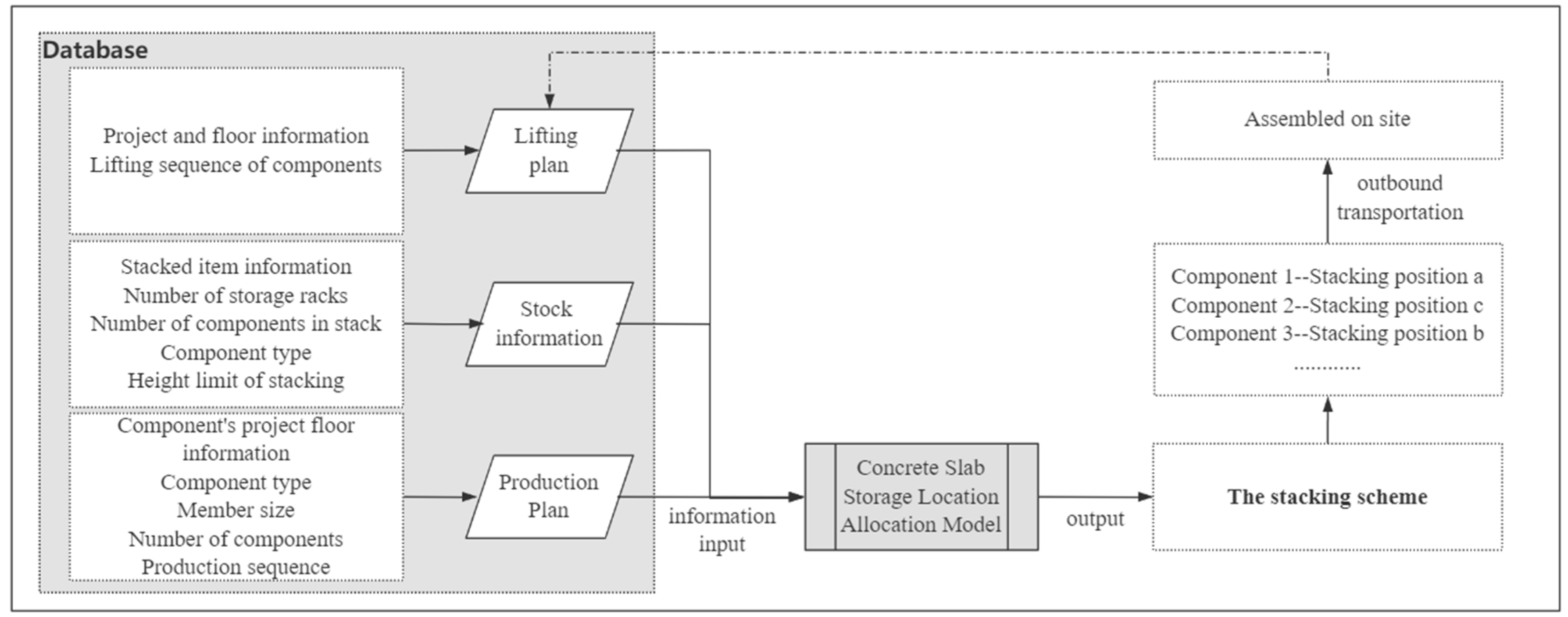
3. Allocation Process for Storage Locations of Components

In this paper, heuristic algorithms and a mathematical model are used to simulate the process of optimizing the storage-location allocation of PC slabs. The flow chart is shown in Figure 2. First, the relevant attribute information of the PC slab is determined in the design and production stage, including the project floor to which it belongs, the length, width, and type of the component, the weight, the serial number of the component, the number of storage racks required, etc. As each project has an assigned person who is responsible for generating installation plans, the sequence is typically available and provided to the stacking crews as one of the inputs for generating stacking plans. The database for generating the stacking plans is constructed through the collection of this information. Then, the PC slab storage-location allocation model reads the production plan information, component location information, and component lifting plan from the database as a basis for judgment and information input. Finally, the heuristic algorithm is used to solve the model, and optimized stacking plans are obtained, which can assign the PC slabs off-line in this batch to appropriate stacking positions. The simulation model is then exited after allocation.

4. Research Methodology

This section describes the two defined goals (stacking stability and secondary-sorting workload) in more detail, and explains how they are used as metrics to generate stacking plans and in a quantitative manner to generate optimized stacking plans.

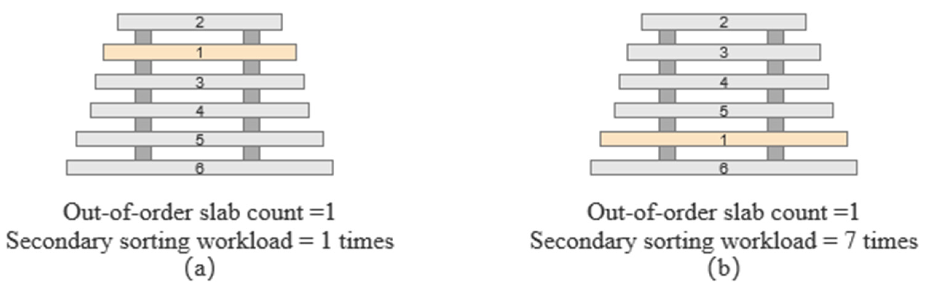
4.1. Metrics to Identify Stacking Problems of PC Slabs

Since construction management literature has few metrics that define the stacking stability of precast PC slabs, we based our knowledge on the stacking of containers. Zhang and Lee optimized container reorganization and ship stability by considering factors such as the height of the center of gravity during container stowage [28]. Therefore, in this study, the authors chose the height of the center of gravity to evaluate the stability of horizontal stacking. The principle of the center of gravity is that the lower the center of gravity of the stack, the higher its stability—because the lower the center of gravity is, the line of action of the center of gravity will not easily cross the fulcrum during the stacking movement—and vice versa. Generally, the weight of precast concrete laminates is heavy, and dunnage needs to be placed in each layer of laminates. Compared with the base contact-surface criterion, the center of gravity criterion is more applicable to the stacking of PC slabs. Therefore, the stability of stacking is calculated using this center of gravity criterion as follows:
Stacking   stability = 1 i w e i g h t   o f   i t h   P C   s l a b   i n   t h e   s t a c k i n g l a y e r   o f   i t h   P C   s l a b
The second metric for analyzing stacking plans is secondary-sorting effort, which measures the amount of work the installer does to realign the slabs. When stacking and installing a set of prefabricated slabs in a single stack, the last-in-first-out (LIFO) principle must be followed, which means that the slabs stacked last and at the top of the stack need to be unloaded first [29]. When looking for slabs to install first according to the installation plan, workers may need to remove several slabs at the top of the stack until the slabs to be installed can be moved to the installation area and installed. In order to evaluate the secondary-sorting workload of the stacking scheme, the authors calculate the secondary-sorting workload for each stacking as follows:
Secondory   sorting   workload = Total   number   of   movements   -   Optimal   number   of   movements
where the total number of movements is the sum of all moves required to install all slabs in the stack, and the optimal number of movements is the number of moves required to install the stack where no re-moving moves are required during installation. The ideal case is when the optimal number of moves is the same as the number of slabs in the stack. To allow for multi-item comparisons, this secondary-sorting workload is calculated assuming an additional stack space to temporarily stack slabs that are not yet installed.
Secondary-sorting workload is used to evaluate the stacking plans in relation to the additional installation work required rather than the number of slabs that are out of the installation sequence, because the secondary-sorting workload captures the amount of additional work more accurately. For example, Figure 3 shows two example stacks that have the same number of slabs that are out of the installation sequence, but a different reshuffling effort. In these two stacks, slab 1, which should be installed first, is on the second and fifth layers from the top, respectively, and the other slabs are stacked in the order of installation. Therefore, in both cases, the number of slabs not in order of installation is 1. However, the secondary-sorting workload is different in these two stacks. For example, in Figure 3a, slab 2 should be removed from one side of the original stack, and once slab 1 has been moved to the installation area, slab 2 and other slabs can be installed in the order in which they were stacked. Therefore, it has one instance of secondary-sorting work. Meanwhile, in Figure 3b, slabs 2~5 must be removed to obtain slab 1; slabs 2~5 must be moved to the side, and slabs 3~5 must then be moved on top of slab 2. Once slab 1 is installed, slabs 3–5 are moved back to the top of the original stack, and slab 2 can then be installed. Therefore, in this case, the stack has seven instances of secondary-sorting work. This shows that the secondary-sorting work metric is a better indicator of how much additional installation work is expected than the metric measuring the number of slabs out of installation order. Using these two metrics, the authors construct a storage-location allocation model for PC slabs targeting secondary-sorting workload and stacking safety.

4.2. Building Mathematical Models

4.2.1. Basic Problem Descriptions

There are several storage racks placed in the yard of a prefabricated component plant, and each storage rack is stacked with up to six PC slabs. In the PC slab storage-location allocation problem (SLAP), SAP and CRP are two important problems to improve the operational efficiency of the yard. SAP is described as the order in which a batch of PC slabs will come off the line is known, and this batch of PC slabs will be temporarily stored in storage racks in that order; CRP is described as the known stacking-state of the components, according to the sequence of components out of the storage rack, to lift the prefabricated components from the storage rack to install. Since the effect of location allocation directly affects the operational efficiency of lifting and installation, it is necessary to develop a reasonable stacking plan when the components are in the factory. Considering the large size and heavy weight of the prefabricated components, the handling process is prone to knocking and damage; as such, when the components are stacked, the objective of reasonable allocation of stacking-positions is to minimize the secondary lifting during the installation of the components on the premise of ensuring the stability of stacking on each storage rack.
We describe the SAP and CRP problem synergistically as follows: given J × K locations (K is the layer height and J is the number of storage racks), ( i , σ ( i ) ) i = 1 J is the sequence of stacked plates ( i , σ ( i ) ) which is the i-th put in and the σ ( i ) one taken out. The problem is: as in Figure 4, PC slabs are placed in the given J × K positions in order of entry, and the number of flaps and operations are minimized when the PC slabs are taken to satisfy the stability premise.

4.2.2. Model Assumptions and Concept Definitions

(1)
Model assumptions
  • Storage racks of known size and only one slab per layer;
  • Component scheduling sequence and installation sequence are known;
  • Meet the stack height limit to ensure the quality of the PC slab and the safety of stacking;
  • The concrete slabs of the same project floor and the same batch should be stacked in the same stack as much as possible. This principle can reduce the number of secondary handling in the outbound operation when the outbound plan is optimized.
(2)
Definition of basic concepts
  • Stack. Each storage rack forms a stack;
  • Target slab. Sorted according to the installation order of the PC slabs, the earliest PC slab that needs to be lifted is called the target slab;
  • Interference slab. If there is an interference phenomenon caused by the PC slab placed above the target plate, the PC slab is called an interference plate or a secondary-lifting-adjustment slab;
  • Priority. There are i PC slabs, and the number {1, 2,…, i} is used to indicate the order of installation. Each PC slab corresponds to a number, which is the priority of the PC slab. No. 1 has the highest level, which means that the PC slab is the target slab in the current state;
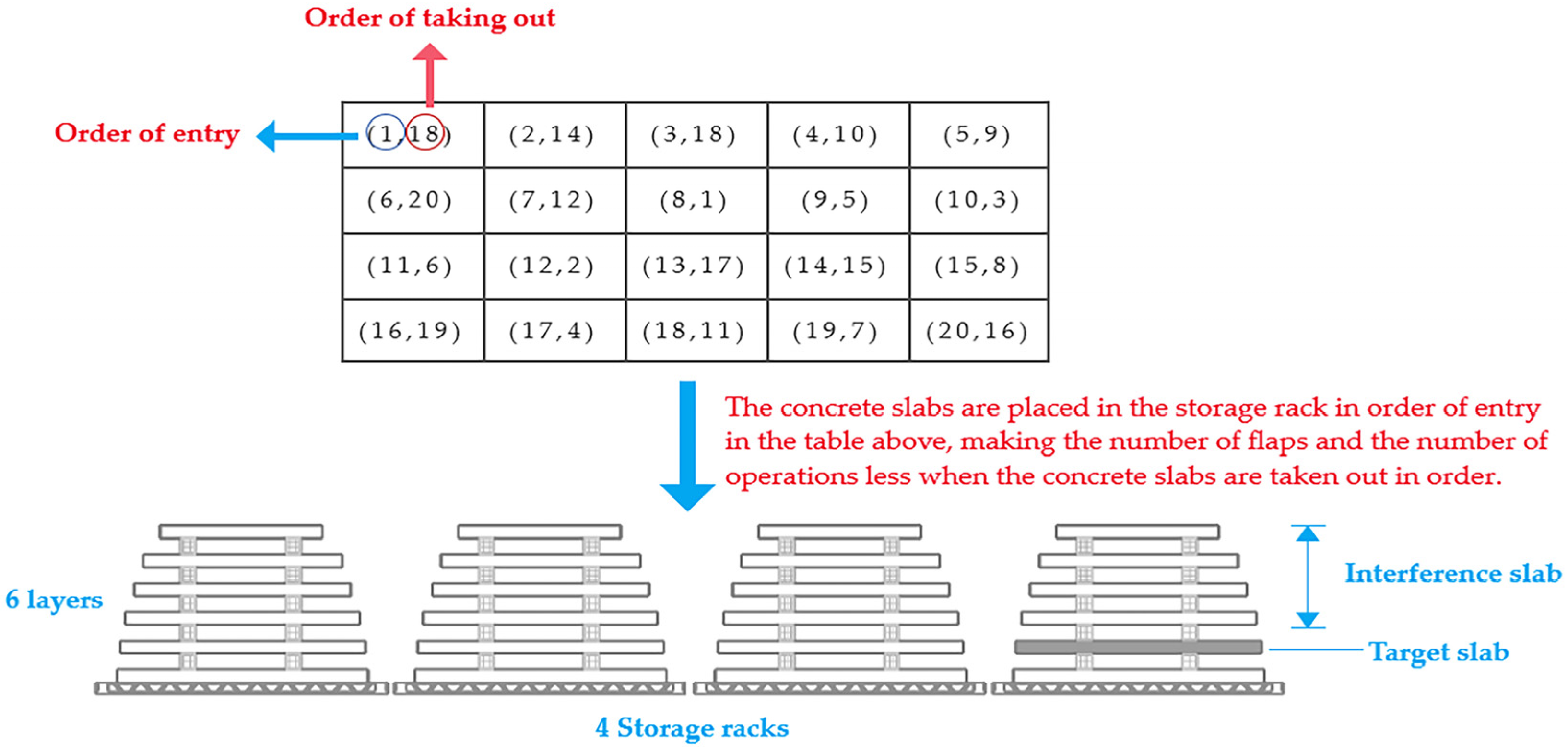
  • Enter sequence A. Suppose a batch of PC slabs is to be stacked, and the column vector A indicates that the PC slabs are stacked in the order of the line. Any element in A represents the priority of the PC slabs, that is, the order of taking-out;
  • Slab matrix B. It is assumed that there are J stacks of k layers in the stacking area, and the matrix B represents the position state of the PC slab. Any element in B means that there is a PC slab in a slab position. If the priority is b, then B(j, k) = b > 0 means that the PC slab with the b-th installation order is placed in the slab position slot (j, k); B(j, k) = 0 means that there is no PC slab on the slab slot (j, k), which is a vacancy.

4.2.3. Mathematical Modeling

In order to clearly describe the model, the decision variables and parametric variables used in the formula are explained as follows.
The parameter variables:
I—The number of PC slabs, I = {1, 2, 3, ……, i};
J—The number of storage racks, J = {1, 2, 3, ……, j};
Gi—The weight of PC slab i;
hj—The initial number of layers of the stack j;
K—Layer height of storage rack j, K = {1, 2, 3, ……, K};
P(i)—The priority of the i-th PC slab, P(i) = {1, 2, 3, …, I};
Slot (j, k)—The slab position of the j-th stacking layer k
Q—A sufficiently large positive number, Q >> 0.
The decision variables:
Xijk indicates whether the position slot(j, k) is occupied by the s-th PC slab. Xijk = 1 if the concrete slab i is on the kth layer of the storage rack j, otherwise Xijk = 0;
Rj(k-z) indicates whether there is an interference slab between the PC slabs on the slab positions slot(j, k) and slot(j, k-z), assuming that the PC slabs a and b are stacked on the positions slot(j, k) and slot(j, k-z), where z = 0,1,2, …,k − 1. Rj(k-z) = 1 if p(a) < P(b), otherwise Rj(k-z) = 0.
The objective function:
min f 1 = i = 1 I j = 1 J k = 2 K z = 1 k 1 R i j ( k z ) ,
min f 2 = i = 1 I j = 1 J k = h j K G i j k K X i j k ,
subject to:
h j K 6 ,
i = 1 I k = 1 K X i j k 1 ,   i I ,
i = 1 I X i j k 1 , j J , k = h j , K ,
i = 1 I X i j k i = 1 I X i j ( k 1 ) , i I , k = h j , K ,
i = 1 I P ( i ) ( X i j k X i j ( k z ) ) ( i = 1 I X i j k 1 R j ( k z ) ) Q ,
X i j k { 0 , 1 }   , R j ( k z ) { 0 , 1 } , i I , j J , k = h j , , K ,
i = { 1 , 2 , , I } , j = { 1 , 2 , J } , k = { 1 , 2 , , K } ,   P ( i ) = { 1 , 2 , , I } ,   Q 0
The objective function (1) is to minimize the number of readjustments of the PC slab members; the objective function (2) represents the lowest center of gravity (maximum stability) of the stack. Constraint (3) means that the number of layers in the storage rack can-not exceed the given maximum value; Constraint (4) means that the PC slab i can only be stored on a certain layer of a stacking position; Constraint (5) means that each position can store only one PC slab; Constraint (6) means that any PC slab is not allowed to be placed in the air; Constraint (7) means that the when PC slab with higher priority is in the lower layer, flip slabs are required (PC slabs a and b are stacked in slot(j, k) and slot(j, k-z) respectively, and P(a) < P(b); then, when a is removed, b must be removed first, recording one turn over the slab, that is, Rj(k-Z) = 1); Constraint (8) means the value range of the decision variable; Constraint (9) represents the range of variable values.

4.2.4. Simplifying the Storage-Location Allocation Model

Currently, there are many methods to deal with multi-objective optimization problems, and one commonly used method is the assignment method, which has obvious features and is simple and easy to implement. However, in this problem, because the two objective functions have different magnitudes and different value ranges, if the simple assignment method is used directly, some objectives may be weakened and it is difficult to obtain the overall optimal effect. Specifically, the algorithm is used to find the optimal value for a single objective, and then the objective function is normalized based on the optimal value of each objective function. The decision maker then assigns weights to each sub-objective function according to the actual situation, and finally the multi-objective problem can be transformed into a single-objective problem. The sub-objective functions F1 and F2 obtained by the normalization of the magnitudes and the total objective function F are as follows.
F 1 = f ^ 2 f 1 f ^ 1 + f ^ 2 ,
F 2 = f ^ 1 f 2 f ^ 1 + f ^ 2 ,
min   F = P 1     F 1 + P 2 *   F 2 ,
where f 1 ^ represents the optimal value of the single-objective function when the number of readjustments of the PC slab is the least, f 2 ^ represents the optimal value of the single-objective function when the stacking stability is optimal, and P 1 and P 2 indicate that the decision maker assigns weights to the two respective optimization objectives.

5. Solution Procedures for the Storage Location Assignment Problem

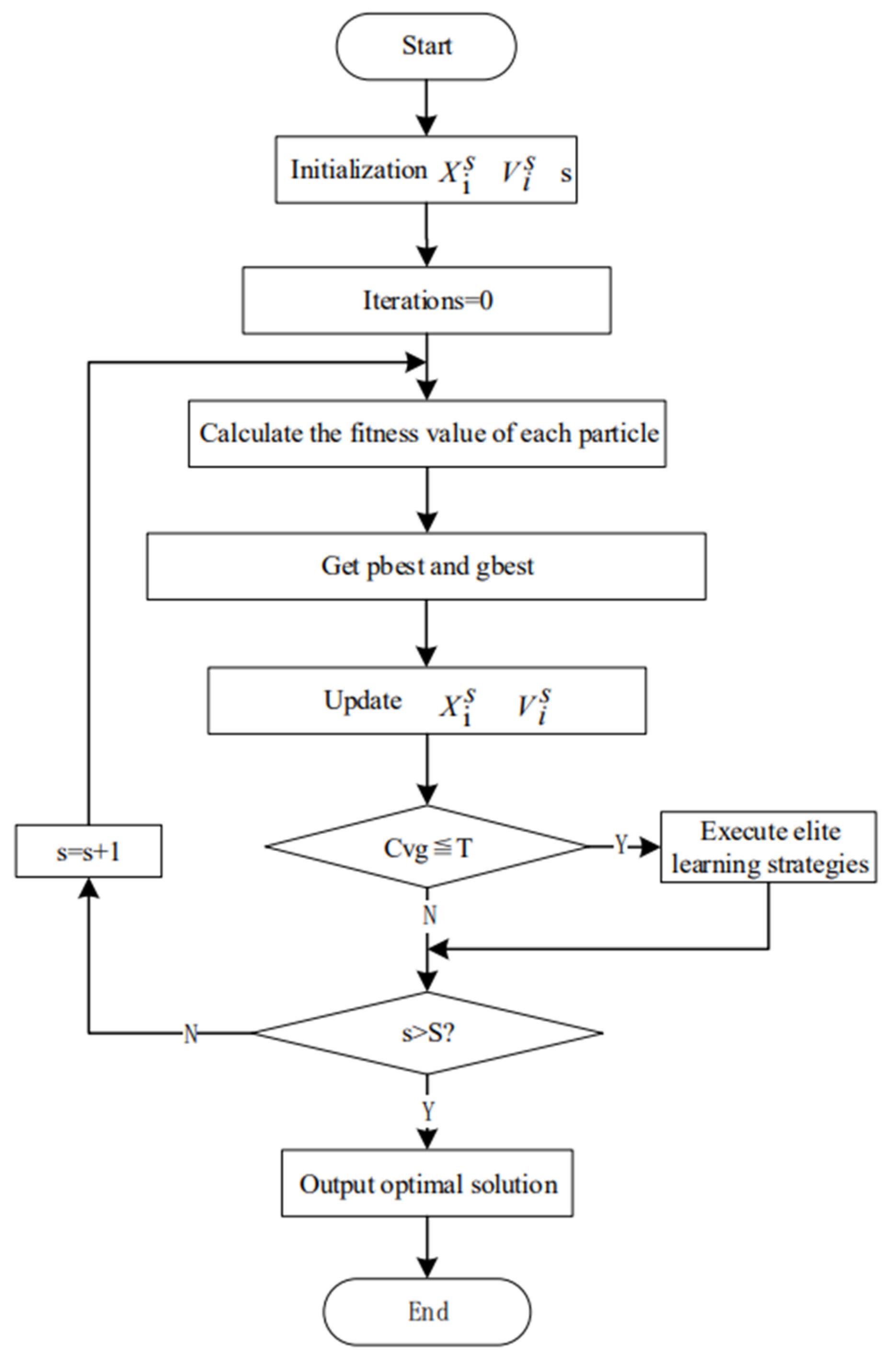
5.1. Brief Introduction to the Particle Swarm Optimization Algorithm

As a generalization of the classic Bin Packing problem, when the scale of the solution increases, an exact algorithm is difficult to solve in an effective time, whereas a heuristic algorithm abandons the completeness of the solution-space but can obtain near-optimal solutions in an acceptable time. Therefore, it has gradually become a research hotspot. The particle swarm optimization (PSO) algorithm has the advantages of strong group diversity, a simple coding method and easy implementation of working principles, and has been widely used in solving various optimization problems in recent years [30]. However, the PSO algorithm also has the disadvantages of low swarm intelligence, slow convergence in the later stage of iteration, and ease of falling into superiority. In response to these problems, some scholars use machine learning assistance to improve the solution performance of particle swarm optimization. Zhan Z et al. used the orthogonal learning method to improve the speed update operator of the PSO algorithm, and guided the particle’s flight direction through the orthogonal combination of the particle’s individual historical learning experience and the group’s optimal historical experience, enhancing the algorithm’s global search ability [31].
Starting from the actual needs of the integrated collaborative management of production and construction in prefabricated component enterprises, this paper proposes a particle swarm optimization algorithm (ELPSO) based on the elite learning strategy for the stacking problem of PC slabs in order to solve the SLAP problem. In the process of evolution, the convergence index Cvg is used to judge whether the population is in the “converged” state. When the population is in the convergent state, the activity of the particles is enhanced by executing the elite learning strategy, so as to prevent the algorithm from falling into the local optimum. For the stacking problem model above, the key problems to be solved in the design of the ELPSO algorithm are: coding scheme and initial solution generation, population update, execution of elite learning strategy, etc.

5.2. Coding and Initial Feasible Solution Generation Steps

In this paper, natural number coding is adopted, and an integer vector Pr = [Pr1,…,Pri,…,PrI] is used to represent the position of particle r in the I-dimensional space, where Pri represents the target stacking position of ith PC slab in the rth particle, i = 1,…,I; pri = 1,…,J, when Xijk = 1, there is Pri = j. The initial feasible solution generation steps are as follows:
Step 1: Traverse the PC slab set in priority order; for PC slab i, if i ≤ I, go to step 2; otherwise, end.
Step 2: Randomly select a stack position j from the J stack positions, and go to step 3.
Step 3: Determine whether the stacking position j satisfies the constraints (3) to (7). If the height of the stack j is greater than or equal to 6, that is, the constraint (3) is not satisfied, go to Step 2; otherwise, it is further judged whether there is a dangling state after placing it, and if the constraint (6) is satisfied. Otherwise, go to Step 2; then, further judge whether the outgoing priority of the PC slab i that has been stored on the top layer of the stacking position j is prior to the outgoing order of the PC slab i, that is, constraint (7); if not satisfied, record a turn over Plate Rj(k−Z) = 1. Otherwise, Rj(k−Z) = 0; go to Step 4.
Step 4: Store the PC slab i in the stacking position j, set pri = j, and update the height of the stacking position j; go to Step 5.
Step 5: If i = I + 1, go to Step 1. According to the above method, the vector Pr = [Pr1,…,Pri,…,PrI] composed of the target position of one superimposed plate is taken as a particle, and a population containing R particles is generated, that is, the initial feasible solution is formed. Then generate the initial velocity vector Vr = (Vr1,Vi2,…,VrI) for each particle, where each component is a random integer within [−M/2, M/2]. In this way, the randomness of the target stack position and the randomness of the initial velocity ensure the diversity of the initial solution.

5.3. Update Particle Velocity and Position

The particle swarm optimization, or PSO [9], algorithm is an adaptive evolutionary algorithm based on population search and on consistency. Each particle is an N-dimensional vector representing a solution in an I-dimensional solution-space. Through the self-learning of a single particle and the mutual cooperation of a group of particles, the PSO algorithm continuously searches the solution space in a progressively better direction, and finally obtains a satisfactory solution. The velocity and position update formulas in the algorithm are as follows:
V r i s + 1 = ω s V r i s + c 1 r 1 s ( P r i s X r i s ) + c 2 r 2 s ( G i s X r i s ) ,
X r i s + 1 = X r i s + V r i s + 1 ,
where v r d s is the flight velocity of particle r in the I dimension of the population; X r d s denotes the position of particle X r in the i dimension (1 ≦ r ≦ R,1 ≦ i ≦I); s is the current iteration number; ω s is the inertia coefficient of the particle at the sth iteration; c1 and c2 are learning factors; and r 1 s and r 2 s are random numbers uniformly distributed in the interval [0, 1]. The flying speed of particles in the population is not only guided by the individual historical optimal solution p b e s t i s , but also guided by the global optimal solution g b e s t i s . Once the position of the particle changes, it means that a new solution is generated. If the solution is better than the local optimal solution or the global optimal solution, then the solution will be retained.

5.4. Elite Learning Strategies

When the PSO algorithm falls into a local optimum, the global optimal solution gbest itself may stagnate locally due to the lack of other traction forces, and as the number of iterations increases, it is continuously refined in a certain part of the solution space. In this state, the movement of the entire population will gradually slow down, showing an illusion of “convergence”. Aiming at this problem, this paper designs a mechanism to help the population break out of this dynamic; that is, in each iteration process, it is judged whether the population is in a convergent state, and the elite learning strategy is implemented accordingly. Let Pr = [Pr1,…,Pri,…,PrI] represent a particle in the population; the specific steps of the elite learning strategy are as follows:
Step 1: According to Formula (15), define the average distance d r from all particles p r to other particles in the population, where R is the size of the population, and I is the total number of superimposed plates.
d r = ( 1 R 1 ) r = 1 , r 1 R ( i = 1 N ( p r i p r i ) 2 ) 1 2 ,
Step 2: The minimum value of the average distance in all particles is recorded as dmin, the maximum value of the average distance is recorded as d max , and the average distance of the global optimal solution gbest is recorded as d g . According to Formula (16), define the convergence index C v g :
C v g = d g d min d max d min ,
The convergence index C v g mainly reflects the state of the population through the relative distance between the global optimal solution gbest and the entire population distribution. The smaller the C v g , the smaller the distance of gbest relative to the entire population, and the more likely the population is in a “converged” state.
Step 3: Assuming that the convergence threshold is T ∈ [0, 1], if Cvg ≤ T, go to Step 4; otherwise, do not execute the elite learning strategy and go to the next round of population iteration.
Step 4: For the global optimal solution gbest, keeping its target value fg, randomly select a PC slab i from the PC slab set to cancel its storage. The stack height of the stack position pgi to which it belongs is reduced by 1, and all the PC slabs from the top of the stack to the position of i are moved down one layer.
Step 5: According to Constraint (3), reassign a stack position randomly for the PC slab i. For stacking position j, if j = pgi, that is, the randomly generated stacking position is the same as the original stacking position, or the height of stacking position j is equal to 6, the constraint is not satisfied, and the random selection of stacking position is continued; otherwise, go to Step 6.
Step 6: According to the priority of taking out the stacked PC slab i, update the flipping times and heights of other PC slab at the stacking position j, thereby obtaining a new solution gbest*.
Step 7: According to Formula (12), calculate the target value f g * obtained by the new solution gbest*; if f g * ≤ fg, use the new gbest* to replace the original gbest; otherwise, judge whether gbest* is better than the target in the population. For the particle with the largest value p r min , if f g * p r min , replace p r min with gbest*; otherwise, do nothing.
The elite learning strategy is an optional step that is not performed at every iteration. Only when Cvg ≤ T can the activity of the global optimal solution gbest be enhanced by executing the elite learning strategy, guiding it by a positive force and leading the entire population to jump out of the local optimum. It can be seen from the above that the convergence threshold T is the key to judging whether the population is in a convergent state. If the value of T is too small, the ability of the elite learning strategy to jump out of the local optimum will not be fully exerted; however, if the value of T is too large, the population update will be improved. The number of times the elite learning strategy is executed during the process increases the computational burden of the system. Therefore, this paper will determine the convergence threshold T by an experimental method. To sum up, the flow of the ELPSO algorithm is shown in Figure 5.

6. Case Studies

6.1. Data Collection

Through the example simulation of production data from a precast concrete component factory and the corresponding construction project data in Wuhan, Hubei Province, China, the optimal stacking method of PC slabs based on the improved PSO algorithm is demonstrated and verified. The simulation was compiled using Matlab2020b, running on an Intel(R) Core (TM) i5-8300H CPU@ 2.30 GHz with 16 GB of memory space and Windows 10 operating system.
This paper selected two commercial and residential buildings with a prefabrication rate of 60%. There are 450 PC slabs, and a tower crane is used for lifting and installing prefabricated components. Three sets of data, (30, 5), (60, 10), and (100, 17), are selected (number of PC slabs, number of storage racks) for testing. At the same time, in this project simulation, since the two objectives targeting the number of readjustments of the components and the maximization of the stacking stability are equally important, the weights of the two objectives are both set to 0.5. The target value of the solution obtained by the algorithm was recorded, and the performance of the ELPSO proposed in this paper was verified and compared with the actual stacking scheme generated by the stacker during the project, including the number of storage racks required, the secondary-sorting workload, stacking stability, on-site lift time, and degree of optimization.

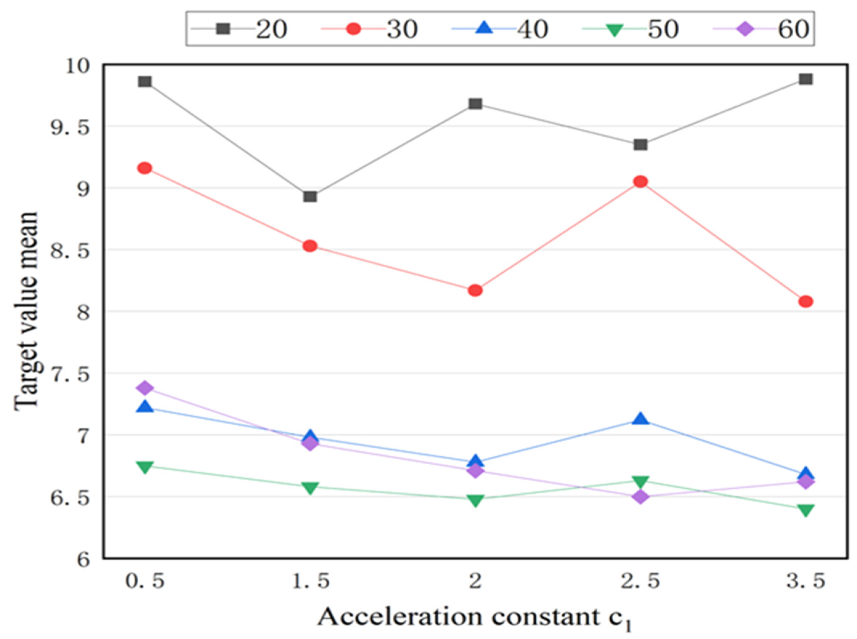
6.2. Analysis of Important Parameters

The initial inertia coefficient of the algorithm is set to wmax = 0.9, wmin = 0.1. The maximum number of iterations of the particle swarm is S = 1000; for comparability, in this paper, the acceleration constants are taken as, respectively, c1= {0.5, 1.5, 2.0, 2.5, 3.5} and c1 + c2 = 4.0, and the scale of the particle swarm is taken as, respectively, R = 20,30,40,50,60; a total of 5 × 5 groups of parameter combinations are tested. For the calculation example where (number of PC slabs, number of storage racks) is (60, 10), each group of data was tested 10 times, and the average target value was counted. The results are shown in Figure 6.
Figure 6 shows that as the number of particles increases, the target value decreases, but the decreasing trend of the target value gradually becomes flat. When the number of particles increases from 40 to 60, the average target value remains basically the same; on the other hand, when the acceleration constant c1 is 2 or 3.5, the experimental results are better. Therefore, this paper chooses the parameter values of particle number R = 50 and acceleration constant c1 = 2.0.
In this paper, for the calculation example where (number of PC slabs, number of storage racks) is (60, 10), the convergence threshold T is taken as {0.02, 0.04, 0.06, 0.08, 0.10, 0.12} for six sets of tests, and the calculation results are shown in Table 1.
The data show that the target value does not decrease monotonically with the increase of the convergence threshold T, while the running time increases sharply with the increase of the T value. When the convergence threshold T = 0.06, the target value is the smallest and the computing time consumed by the system does not increase significantly; thus we chose T = 0.06 as the convergence threshold.

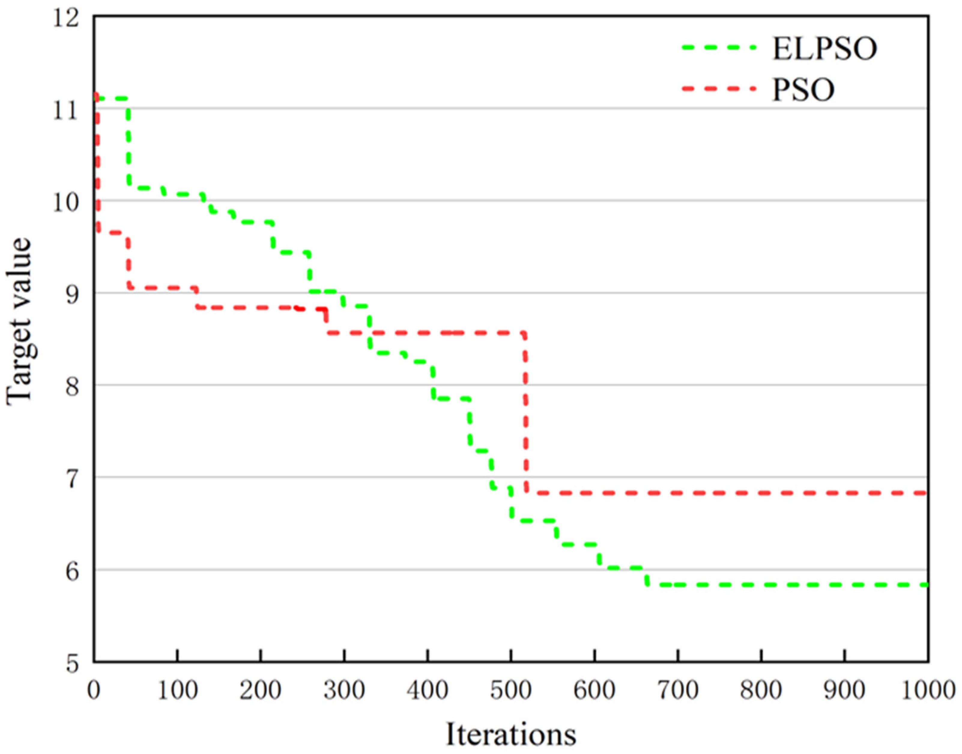
6.3. Simulation Results

Table 2 lists the target averages of 20 groups of tests using the standard PSO and the improved ELPSO algorithm for the stack allocation model proposed in this paper under different data scales. The data show that, without increasing the number of storage racks required, the optimization algorithm’s stacking plan has lower total readjustment effort and improved stacking stability than plans generated using the conventional empirical method. According to the actual calculation, the lifting operation time of each PC slab is about 10 min. It is assumed that the time required for each additional secondary lifting is the same as the time required for the normal lifting of the PC slab. In the three sets of data, as the number of readjustments of the components and the time of processing increases, the optimization degree decreases, but the overall optimization degree also reaches more than 60% and 20%, respectively; additionally, the improvement range of stacking stability is about 8% to 11%. Since the target constraint is directly related to project time and cost, the secondary lifting of components can translate into a 20% savings in lifting time and cost. Therefore, it can be inferred that the stacking plan generated using the improved algorithm increases the cost effectiveness of precast concrete laminates. Since these components are only a part of the project case, and this procedure can be extended on other stackable horizontal components, the absolute impact of the overall project time and cost will be even greater. Similarly, higher stacking stability further reduces the potential risks of damaged PC slabs, all of which will positively impact project costs. In summary, the case study demonstrates the effectiveness and practicality of the optimal stacking allocation model and the improved particle swarm algorithm. This can guide stacking crews to effectively develop stacking plans for horizontal components such as PC slabs, shorten component lifting time, and improve project performance.
Figure 7 compares the convergence curves of the two algorithms, PSO and ELPSO, for the example where (number of PC slabs, number of storage racks) is (60, 10). When the number of iteration steps is small, the convergence curves of both algorithms decrease significantly, but PSO quickly falls into the local optimum while ELPSO, under the control of the elite learning strategy, continues to maintain a downward trend in its convergence curve. The target value position tends to converge. It is shown that the improved PSO algorithm (ELPSO), through the elite learning strategy, can get a better solution on the target.

6.4. Discussion

The stacking plan is characterized as the allocation of space for the scheduling of the components into the stacking process. During this phase, the plant must find out what components are in production for the project floors and information about the project inventory. In addition, it must determine the construction schedule of the project and the sequence of component installation at the construction site. According to the simulation results of this paper, the secondary-sorting problem of PC slabs is mainly due to the currently high number of factory production projects and time constraints, coupled with the low rates of standardization between of the deepening designs of prefabricated components at this stage; the scheduling scheme proposed by the factory is mostly based on the premise that the scheduled demand of the assembly construction site, and the efficient use of modes to develop the production sequence of components and the resource-scheduling scheme, can effectively improve the efficiency of factory production [32,33,34,35]. However, this scheme often causes the problem where components are stacked in a confusing manner, which affects the subsequent lifting at the assembly construction site. Secondly, there is a certain lack of coordination and exchange mechanisms between the prefabricated component production plant and the construction site. Under the many restrictions, the operators of the production plant rarely, or only with great difficulty, consider these target constraints when the components are stacked. Usually, more attention is paid to stacking safety, trying to reduce the number of storage racks, or increasing the spatial utilization rate of the yard to transport the components to the scene at the cost of as little as possible. Finally, when the components are stacked, most of them rely on manual experience to assign stacking positions. It is difficult to coordinate the stacking strategy of PC slabs according to both the upstream production plan and the downstream lifting plan in order to quickly and accurately generate the best stacking plan. The consequences will cause the PC slab stack to be unreasonable, and with this order of component stacking, it is difficult to achieve direct lifting installation. Although there have been previous studies on the optimization of the stacking plan of prefabricated components, they all focus on the wall panel components of panelized structures. However, the two have different stacking rules and requirements, and the simulation results of this study are difficult to compare between them. To further verify the effectiveness and applicability of the model, this case was analyzed, and the results of the simulation model were sent to multiple experienced project managers for feedback, whereupon it was considered that the model is efficient and practical.
In addition, in the current practice, it can be found that—due to the limited number of components per transport batch—adjacent installation serial number components are placed in the same storage rack as much as possible. Although this can minimize the number of storage racks, if the orderliness of the scheduling sequence is poor, it can also lead to certain components being too dispersed, increasing the difficulty of transport operations. From the model proposed in this paper, small batches of lifted components can improve stacking stability and readjustment efforts. However, segmentation may reduce the optimization performance of the model because the orderliness of the scheduling sequence is another factor affecting the dispersion of the adjacent lifting components. In future research, firstly, the model can be appropriately adjusted according to the actual constraint limits so that the model can be extended and applied to other precast concrete horizontal members to further enhance the applicability of the model. Other constraints and optimization objectives should also be taken into account in order to be closer to the actual situation—for example, whether the scheduling plan takes into account the final lifting sequence to some extent—as well as to improve the whole supply chain of the lifted elements by an integrated and holistic approach.

7. Conclusions

This paper considers a stacking problem for PC slabs, which are produced according to a pre-production sequence. All the finished PC slabs are temporarily stacked on a given number of storage racks and then transported to the site for delivery, where the site crane can only move one PC slab simultaneously. A stack storage plan needs to be developed to ensure that the stacks are stable in the storage racks to minimize the number of readjustments during the lifting phase. Therefore, an optimization model of stack-position allocation is constructed to achieve minimum readjustment times and optimum stacking stability. According to the model, the coding scheme is designed and the initial solution generation step is solved by the PSO algorithm. Aiming at addressing the disadvantage of PSO algorithm, that it easily falls into the local optimum in the process of optimization, an elite learning strategy particle swarm algorithm (ELPSO) is designed to improve the ability of the algorithm to jump out of the local optimum. Finally, the effectiveness of the method was verified by the instance. Compared with the manual stacking plans, the optimization algorithm can quickly and accurately generate the stacking plans without increasing the storage rack, improving the stack’s stability and reducing the secondary-resorting workload during installation. For example, in this case study, the algorithm was used to generate a stacking plan for 100 PC slabs; the stacking stability was increased by 8%, and the number of readjustments was reduced by 64.44%. Thus, the method supports stacking plans by generating stacking plans in a more cost-effective and installation-efficient manner than current practice.
The good results obtained in terms of quality and calculation time of the solution show that it is feasible to develop an integrated application module for the automatic al-location of stacking positions in the current yard-management system. Based on this approach, together with the introduction of emerging technologies such as RFID that allow automatic data capture, the management content of the precast yard-management system can be further enhanced to achieve a more optimized and integrated supply chain and construction management of precast components, thus leading to a greater competitive advantage for assembled buildings.
However, this study has some limitations that need to be addressed in the next step of the research. Firstly, for the space resources and loading and unloading resources within the yard system, the research in this paper considers them as independent of each other, and the two resources should be further linked to achieve the overall optimum. This optimization also needs to consider more restrictions and constraints; the penalty degree of schedule-adjustment needs to be considered, and further research is needed. Finally, the orderliness of the PC slab component scheduling plan needs to be further explored in terms of the size of the impact on the number of readjustments after stacking.

Author Contributions

Writing responses to comments, writing revised manuscript, validation, data curation, resources, Y.Z.; Methodology, software, writing—original draft preparation, Q.G.; Supervision, S.W. All authors have read and agreed to the published version of the manuscript.

Funding

This research was funded by the “Technology Boosts Economy 2020” Industrial Application of BIM-based Prefabricated Building Integrated Design Technology under grant number 2020ZLSH08.

Institutional Review Board Statement

Not applicable.

Informed Consent Statement

Not applicable.

Data Availability Statement

Data is available with the first author and can be shared upon reasonable request.

Acknowledgments

Authors are thankful to respondents of the multi-regional survey. The time they spared for this study has enabled most of the findings in this study.

Conflicts of Interest

The authors declare no conflict of interest.

References

  1. Xu, Z.; Wang, S.; Wang, E. Integration of BIM and energy consumption modelling for manufacturing prefabricated components: A case study in China. Adv. Civ. Eng. 2019, 18, 1609523. [Google Scholar] [CrossRef]
  2. Polat, G. Factors affecting the use of precast concrete systems in the United States. J. Constr. Eng. Manag. 2008, 134, 169–178. [Google Scholar] [CrossRef]
  3. Wu, G.; Yang, R.; Li, L.; Bi, X.; Liu, B.; Li, S.; Zhou, S. Factors influencing the application of prefabricated construction in China: From perspectives of technology promotion and cleaner production. J. Clean. Prod. 2019, 219, 753–762. [Google Scholar] [CrossRef]
  4. Li, C.Z.; Hong, J.; Fan, C.; Xu, X.; Shen, G.Q. Schedule delay analysis of prefabricated housing production: A hybrid dynamic approach. J. Clean. Prod. 2018, 195, 1533–1545. [Google Scholar] [CrossRef]
  5. Lee, Y.; Kim, J.I.; Khanzode, A.; Fischer, M. Empirical study of identifying logistical problems in prefabricated interior wall panel construction. J. Manag. Eng. 2021, 37, 05021002. [Google Scholar] [CrossRef]
  6. Fang, Y.; Ng, S.T. Genetic algorithm for determining the construction logistics of precast components. Eng. Constr. Archit. Manag. 2019, 26, 2289–2306. [Google Scholar] [CrossRef]
  7. Liu, D.; Li, X.; Chen, J.; Jin, R. Real-time optimization of precast concrete component transportation and storage. Adv. Civ. Eng. 2020, 18, 5714910. [Google Scholar] [CrossRef] [PubMed]
  8. Shewchuk, J.P.; Guo, C. Panel stacking, panel sequencing, and stack locating in residential construction: Lean approach. J. Constr. Eng. Manag. 2012, 138, 1006–1016. [Google Scholar] [CrossRef]
  9. Guo, C. Panel Stacking and Worker Assignment Problems in Residential Construction Using Prefabricated Panels: A Lean Approach. Ph.D. Thesis, Virginia Tech, Blacksburg, VA, USA, 2010. Available online: https://hdl.handle.net/10919/77092 (accessed on 20 September 2022).
  10. Sörensen, K.; Vanovermeire, C.; Busschaert, S. Efficient metaheuristics to solve the intermodal terminal location problem. Comput. Oper. Res. 2012, 39, 2079–2090. [Google Scholar] [CrossRef]
  11. Legato, P.; Mazza, R.M. Managing Container Reshuffling in Vessel Loading by Simulation; IEEE: Piscataway, NJ, USA, 2013; pp. 3450–3461. [Google Scholar] [CrossRef] [Green Version]
  12. Shewchuk, J.P.; Guo, C.; Sarkar, S. Ergonomic design and planning for panelized residential construction. In IIE Annual Conference; Institute of Industrial and Systems Engineers (IISE): Peachtree Corners, GA, USA, 2009; pp. 102–107. [Google Scholar]
  13. Galle, V.; Barnhart, C.; Jaillet, P. Yard crane scheduling for container storage, retrieval, and relocation. Eur. J. Oper. Res. 2018, 271, 288–316. [Google Scholar] [CrossRef]
  14. Caserta, M.; Schwarze, S.; Voß, S. A mathematical formulation and complexity considerations for the blocks relocation problem. Eur. J. Oper. Res. 2012, 219, 96–104. [Google Scholar] [CrossRef]
  15. Caserta, M.; Voß, S. A corridor method-based algorithm for the pre-marshalling problem. In Proceedings of the Workshops on Applications of Evolutionary Computation, Hamburg, Germany, 15–17 April 2009; pp. 788–797. [Google Scholar]
  16. Forster, F.; Bortfeldt, A. A tree search procedure for the container relocation problem. Compute. Oper. Res. 2012, 39, 299–309. [Google Scholar] [CrossRef]
  17. Carpenter, H.; Dowsland, W.B. Practical considerations of the pallet-loading problem. J. Oper. Res. Soc. 1985, 36, 489–497. [Google Scholar] [CrossRef]
  18. Lee, Y.; Fischer, M.; Kim, J.I. Evaluation of reshuffling efforts to comply with installation sequences of prefabricated interior wall panelss from bunks delivered on sit. In Computing in Civil Engineering 2019; American Society of Civil Engineers: Reston, VA, USA, 2019; pp. 635–642. [Google Scholar] [CrossRef]
  19. Lee, Y.; Kim, J.I.; Flager, F.; Fischer, M. Generation of stacking plans for prefabricated exterior wall panels shipped vertically with A-frames. Autom. Constr. 2021, 122, 103507. [Google Scholar] [CrossRef]
  20. Cheng, X.; Tang, L. A scatter search algorithm for the slab stack shuffling problem. In Proceedings of the International Conference in Swarm Intelligence, Heidelberg/Berlin, Germany, 12–15 June 2010; pp. 382–389. [Google Scholar] [CrossRef]
  21. Xue-ping, T.U.; Can-tao, S.H.I.; Tie-ke, L.I. Model and algorithm for the slab location optimization decision problem based on fuzzy matching. Chin. J. Eng. 2011, 33, 376–382. [Google Scholar] [CrossRef]
  22. Zhang, R.Y.; Liu, S.X.; Wang, D.W. Slab Retrieving Problem in Hot Rolling and Its Tree Search Algorithm. Control Decis. 2013, 28, 1707–1712. [Google Scholar]
  23. Ge, P.; Zhao, R.; Sun, D.; Dong, Y. Integrated optimisation of storage and pre-marshalling moves in a slab warehouse. Int. J. Prod. Res. 2022, 60, 2021–2043. [Google Scholar] [CrossRef]
  24. Jang, H.; Lee, S.; Choi, S. Optimization of floor-level construction material layout using genetic algorithms. Autom. Constr. 2007, 16, 531–545. [Google Scholar] [CrossRef]
  25. Hu, W. Automatic construction process of prefabricated buildings on geometric reasoning. In Proceedings of the Construction Research Congress 2005: Broadening Perspectives, San Diego, CA, USA, 5–7 April 2005. [Google Scholar] [CrossRef]
  26. Nguyen, T.H.; Oloufa, A.A. Computer-generated building data: Topological information. J. Comput. Civ. Eng. 2001, 15, 268–274. [Google Scholar] [CrossRef]
  27. Nguyen, T.H. Automated construction planning for multi-story buildings. In Construction Research Congress 2005: Broadening Perspectives; American Society of Civil Engineers: Reston, VA, USA, 2005; pp. 1–10. [Google Scholar] [CrossRef]
  28. Zhang, Z.; Lee, C.Y. Multiobjective approaches for the ship stowage planning problem considering ship stability and container rehandles. IEEE Trans. Syst. Man Cybern. Syst. 2015, 46, 1374–1389. [Google Scholar] [CrossRef]
  29. Lehnfeld, J.; Knust, S. Loading, unloading and premarshalling of stacks in storage areas: Survey and classification. Eur. J. Oper. Res. 2014, 239, 297–312. [Google Scholar] [CrossRef]
  30. Poli, R.; Kennedy, J.; Blackwell, T. Particle swarm optimization. Swarm Intell. 2007, 1, 33–57. [Google Scholar] [CrossRef]
  31. Zhan, Z.H.; Zhang, J.; Liu, O. Orthogonal learning particle swarm optimization. In Proceedings of the 11th Annual Conference on Genetic and Evolutionary Computation, New York, NY, USA, 8–12 July 2009; pp. 1763–1764. [Google Scholar] [CrossRef]
  32. Tharmmaphornphilas, W.; Sareinpithak, N. Formula selection and scheduling for precast concrete production. Int. J. Prod. Res. 2013, 51, 5195–5209. [Google Scholar] [CrossRef]
  33. Yang, Z.; Ma, Z.; Wu, S. Optimized flowshop scheduling of multiple production lines for precast production. Autom. Constr. 2016, 72, 321–329. [Google Scholar] [CrossRef]
  34. Huang, K.; Wu, S.; Wang, M. Study on the storage and transportation optimization of prefabrication factory. In Proceedings of the 22nd ISARC, Ferrara, Italy, 11–14 September 2005. [Google Scholar] [CrossRef]
  35. Dawood, N.; Marasini, R. Visualisation of a stockyard layout simulator “SimStock”: A case study in precast concrete products industry. In Proceedings of the Seventh International Conference on Virtual Systems and Multimedia, Berkeley, CA, USA, 25–27 October 2001; pp. 726–737. [Google Scholar]
Figure 1. Processes of concrete slabs construction (logistical processes highlighted in gray).
Buildings 12 01538 g001
Figure 2. Framework flow chart for allocation of component storage locations.
Buildings 12 01538 g002
Figure 3. Examples of stacks with the same number of slabs outside sequence but different secondary-sorting workloads.
Buildings 12 01538 g003
Figure 4. Schematic diagram of the number of palletization and flap readjustment.
Buildings 12 01538 g004
Figure 5. Flowchart of ELPSO.
Buildings 12 01538 g005
Figure 6. Parameter test result of the PSO algorithm.
Buildings 12 01538 g006
Figure 7. Convergence performance of ELPSO and PSO.
Buildings 12 01538 g007
Table 1. Comparison result of T.
Convergence Threshold TTarget Value MeanRunning Time Mean/s
0.0210.1656
0.048.3873
0.065.6986
0.085.94120
0.106.81182
0.1210.58228
Table 2. Comparison between the actual stacking plan manually generated by the stacking planners during the project and the stacking plan generated by the optimization algorithm for the case project.
Number of PC SlabsNumber of
Storage Racks
ObjectivesPSOELPSO
(This Paper)
ManualDegree of Optimization
(Compared to Manual)
305f1 (secondary sorting)631478.57%
f2 (stacking safety/t)95.46696.712108.16610.59%
Total lifting time/h65.507.3324.96%
6010f1 (secondary sorting)1272875.00%
f2 (stacking safety/t)129.826132.859149.36211.04%
Total lifting time/h1211.1614.6723.92%
10017f1(secondary sorting)24164564.44%
f2 (stacking safety/t)291.982295.615321.8538%
Total lifting time/h20.6619.3324.1720.02%
Publisher’s Note: MDPI stays neutral with regard to jurisdictional claims in published maps and institutional affiliations.

