Article

Assessment of Earth Retaining Performance for Long-Short Piles Composite Structures from Field Experiments and Numerical Analysis

1
Engineering Research & Development Centre for Underground Technology of Jiangxi Province, Jiangxi Key Laboratory of Infrastructure Safety and Control in Geotechnical Engineering, East China Jiaotong University, Nanchang 330013, China
2
School of Civil Engineering and Architecture, Jiangxi Vocational and Technical College of Communications, Nanchang 330013, China
3
Research Center of Coastal and Urban Geotechnical Engineering, Zhejiang University, Hangzhou 310058, China
4
Technology Center, Guangdong Sanhe Pile Co., Ltd., Zhongshan 528414, China
*
Author to whom correspondence should be addressed.
Buildings 2022, 12(10), 1524; https://doi.org/10.3390/buildings12101524
Submission received: 29 August 2022 / Revised: 13 September 2022 / Accepted: 17 September 2022 / Published: 23 September 2022
(This article belongs to the Special Issue Advanced Seismic Technologies in Underground Structures)

Abstract

:
Retaining pile structure is commonly utilized in excavation maintenance design. In recent years, the long-short combined retaining piles have received more and more attention. According to the actual deep excavation engineering, the working mechanism of the long-short, long-double-short, and long-triple-short combined retaining piles was tested in the field. Based on the field test parameters, the finite element model of the test area was established and the simulation results were verified, and the effects of short pile length and pile spacing on bending moment, horizontal displacement of piles, surface settlement, and excavation bottom heave were further investigated. The results show that the bending moment of the long pile is larger than the short pile. The bending moment of the long pile and short pile increases gradually with the increase in the number of short piles. When the combination changes from combination 1 to 3, the peak moment of the long pile and short pile increases by 15.8% and 15.2%, respectively. The maximum displacement is near the pile top, combination 3 has the largest horizontal displacement, and the peak displacement of the long pile and the short pile is 17.21 mm and 17.87 mm, respectively, but almost no effect exists on the horizontal displacement below the excavation bottom. In addition, reducing short pile length and increasing pile spacing will increase bending moment and horizontal displacement of the long and short piles to a certain extent, and this phenomenon is mainly concentrated above the excavation bottom, the influence of short pile length and pile spacing on surface settlement and excavation bottom heave can be ignored.

1. Introduction

For the past few decades, with the development of urbanization, a large amount of land has been occupied due to the continuous expansion of the region in the process of urbanization construction, and the number and scale of excavation and tunnel engineering have also increased, especially the increase of deep excavation engineering [1,2], and the supporting method of excavation is constantly showing new changes [3,4,5]. Furthermore, the efficient application and treatment of soil have become an important goal of social sustainable development. Hence, how to design an economic and safe deep excavation supporting system is one of the main challenges encountered in engineering practice [6,7].
In the existing retaining structure of excavation, many retaining methods have been developed according to different excavation conditions, such as diaphragm wall [8,9,10,11,12], soil nailing retaining wall [13,14,15], and piles with bracing [16,17]. In urban soft soil base area, pile support system is widely used because of its good control effect on the displacement caused by excavation, and the influence of excavation on adjacent buildings or subway is acceptable. As a significant foundation pattern, piles have been widely used in geotechnical engineering, and a large number of scholars have studied the deformation of piles [18,19], earth pressure [20], horizontal mechanical properties of piles [21,22,23], and pile–soil interaction [24,25].
With the application of piles with bracing structure in engineering support, many scholars and civil engineers have also analyzed the support effect of retaining pile. Based on long-strip excavation and square excavation, Cheng et al. [19] simulated the cantilever contiguous piles under partial failure by the explicit finite difference method (FDM), the results show that a partial collapse can cause sharp increases in the internal forces in adjacent intact piles through the horizontal arching effect. Cui et al. [26] presents a case study to investigate the behavior of a large-scale excavation supported by bored piles and inclined steel struts. Chen et al. [27] analyzed the pile-anchor supporting system based on an in situ deep excavation case, and results show that combination of non-prestressed anchor bolts and prestressed anchor cables can effectively save the cost while improving the safety factor of excavation. Zhang et al. [28] conducted a full-scale field experiment on the reinforcement of the high cutting-slopes with newly designed bored piles with retaining walls (BPRWs) along the Lhasa-Nyingchi Railway. They point out that the installed retaining walls cooperate with the bored piles so that the BPRWs overall resistance to bending and overturning is enhanced. It is worth noting that all the above-mentioned studies focused on the equal-length pile, i.e., the lengths of all the retaining piles are the same. Nevertheless, Leung et al. [29] pointed out that the maximum internal force at the bottom of the pile was only about 25% of that at the top of the pile, resulting in the strength of the material at the bottom of the pile could not be fully utilized. Zhang et al. [30] have shown that below the excavation face, the lower part of the retaining structure bears a small bending moment due to the reverse force of the passive earth pressure. It can be seen that the design method of equal-length pile does not make full use of the rules of soil quality condition and the interaction of pile and soil, resulting in engineering waste to a certain extent. Moreover, a considerable number of engineers have applied non-equal length piles as the foundation of buildings [31,32,33]. As a consequence, in the design of retaining pile structure of excavation, the pile length of some retaining piles can be shortened appropriately, and the combination of long-short piles is adopted as the retaining structure of excavation, which has attracted the attention and study of some scholars. Zheng and Cheng [34] investigated the deformation and mechanical properties of long-short cantilever piles in the process of foundation pit excavation through laboratory model tests, and revealed the cooperative working mechanism of long-short piles in the long and short pile retaining structure. Xu et al. [35] established a three-dimensional finite element model of the long and short pile supporting system and gave the calculation method of the long and short pile supporting system. Xu et al. [36] conducted indoor model experiments and finite element models to study the working performance of the long-short pile supporting system under different combinations. In the past, the majority of existing studies were based on model test and numerical investigation for the composite retaining structure of long-short piles, while the field working performance of long-short pile combinations is largely unknown. Hence, it is necessary to further study the composite maintenance structure of long and short piles.
For this purpose, the full-scale field experiments of three combinations of the long-short combined retaining piles were conducted based on the actual excavation engineering, and the further numerical investigation of the test area was performed using the finite element program. Using this approach, the effects of pile length and pile spacing on bending moment, horizontal displacement, ground settlement, and foundation uplift of the excavation bottom were analyzed. Finally, some meaningful conclusions are obtained. It is hoped that the present study can provide a certain reference significance for long-short piles composite retaining structures.

2. Field Test Configuration and Procedures

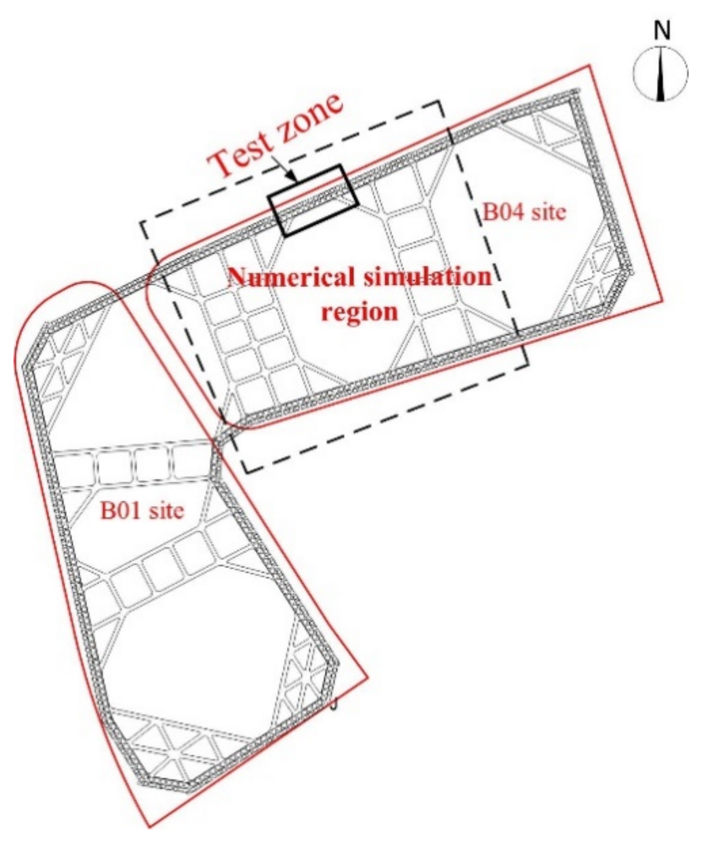
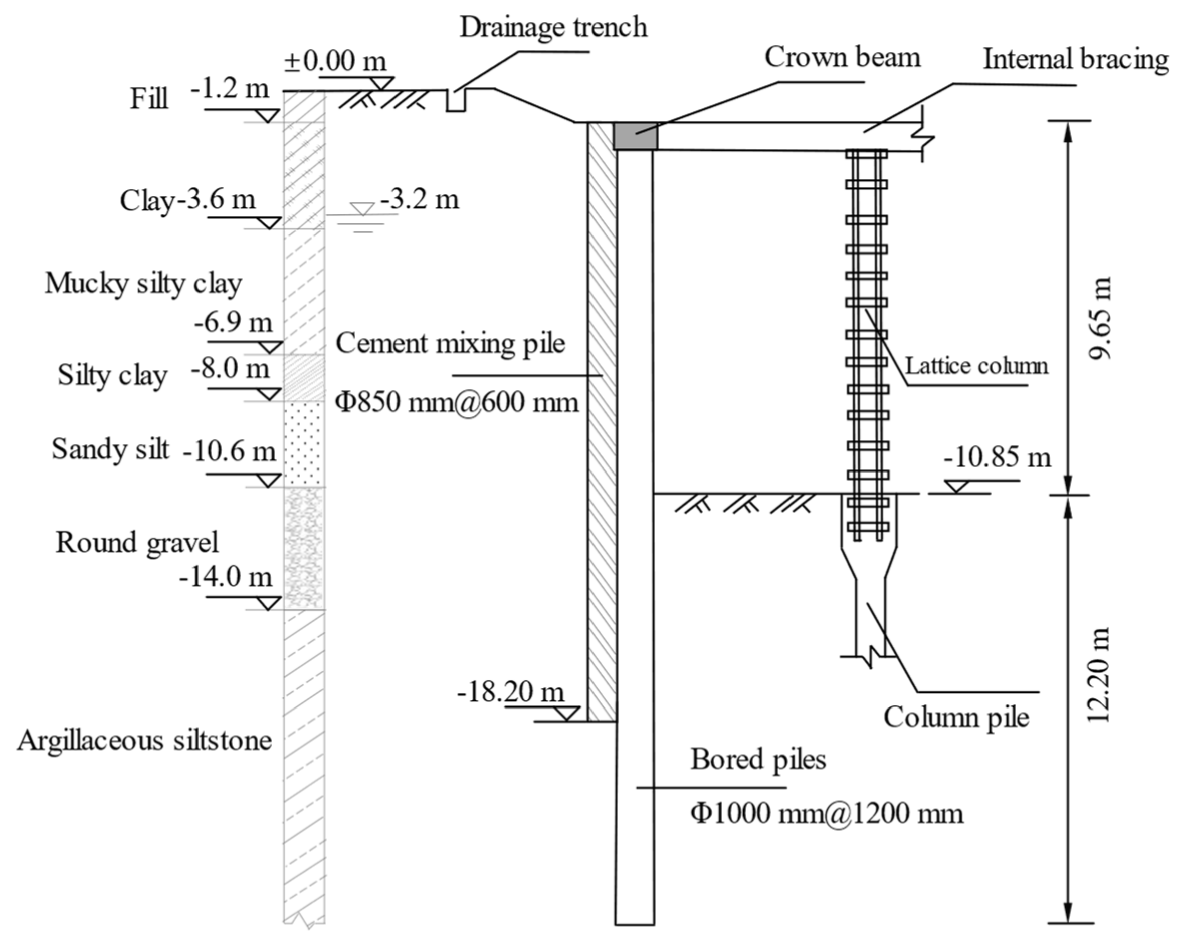
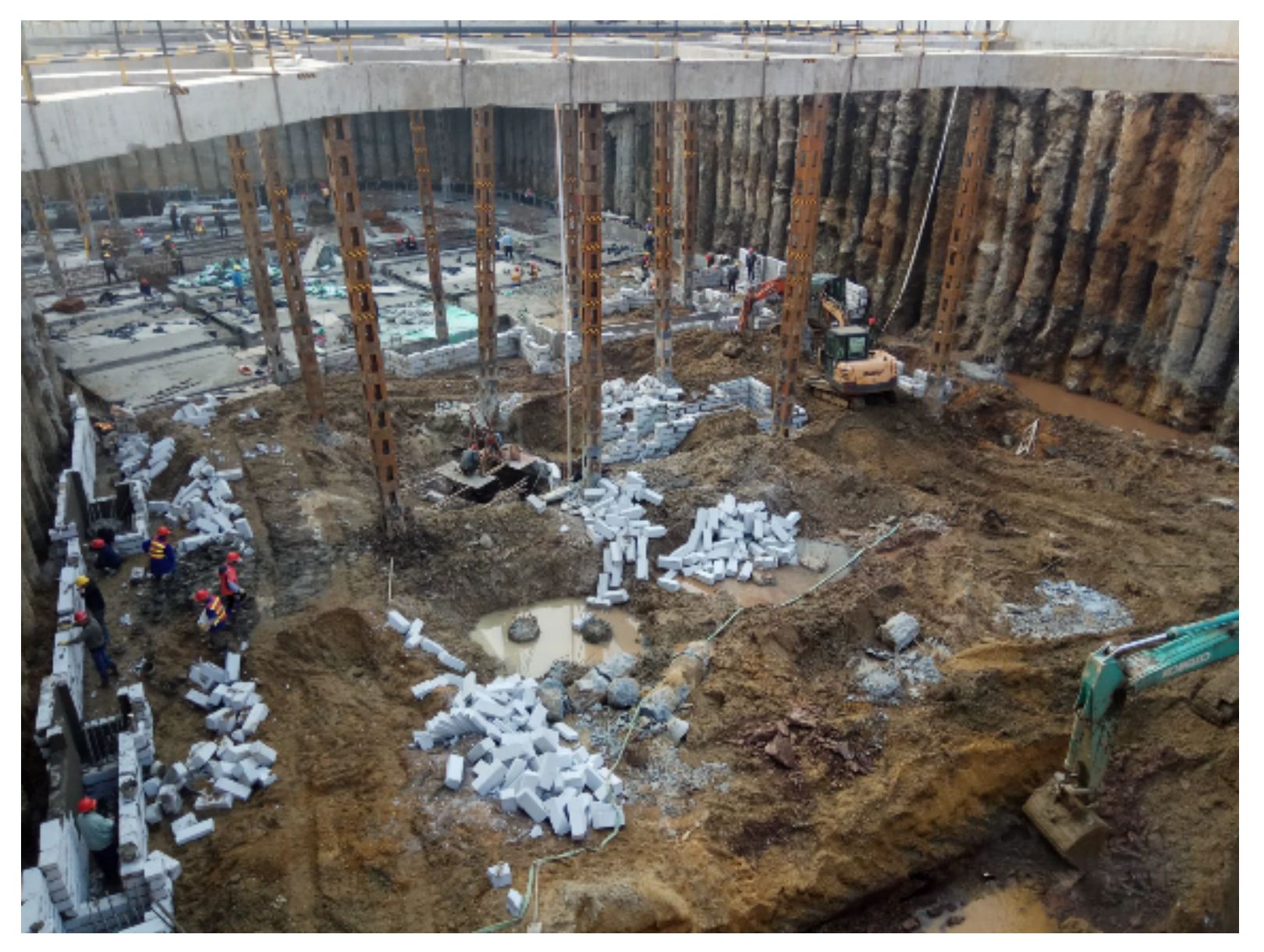
2.1. Field Test Site Engineering Overview

For the deep excavation of an engineering project located in Nanchang city, the plan layout of the proposed site takes on the shape of “L”, as shown in Figure 1. It includes two sites, i.e., B01 and B04, with a circumference of about 470 m and an area of about 5900 m2. The excavation depth of the B01 site and B04 site is 11.45 m and 10.85 m, respectively. In this project, bored piles with a diameter of 1.0 m and spacing of 1.2 m are used as the retaining structure, the ground water level for the excavation site is at −3.2 m. Figure 2 shows the design section and soil distribution of the excavation in the BO4 site.

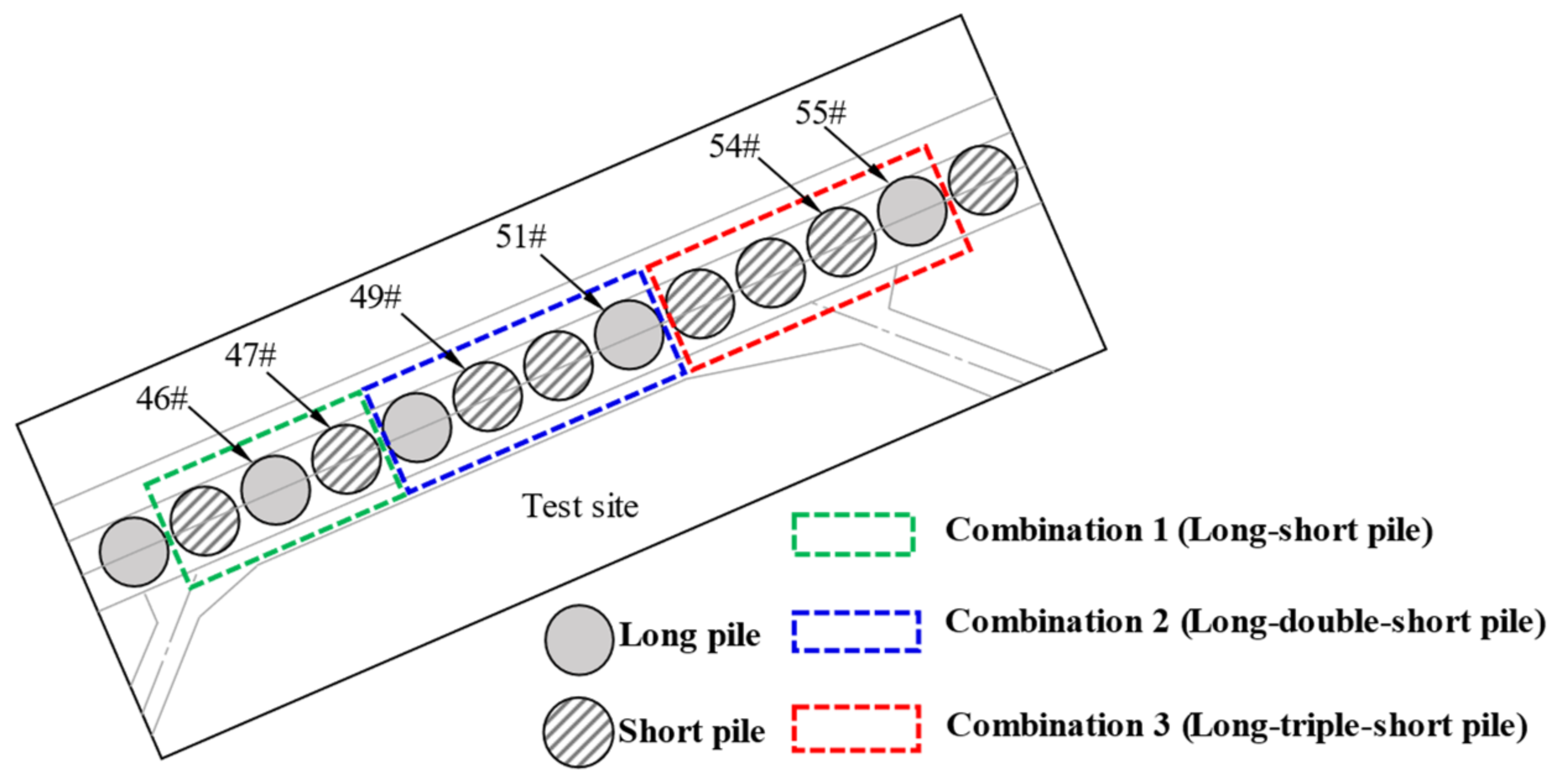
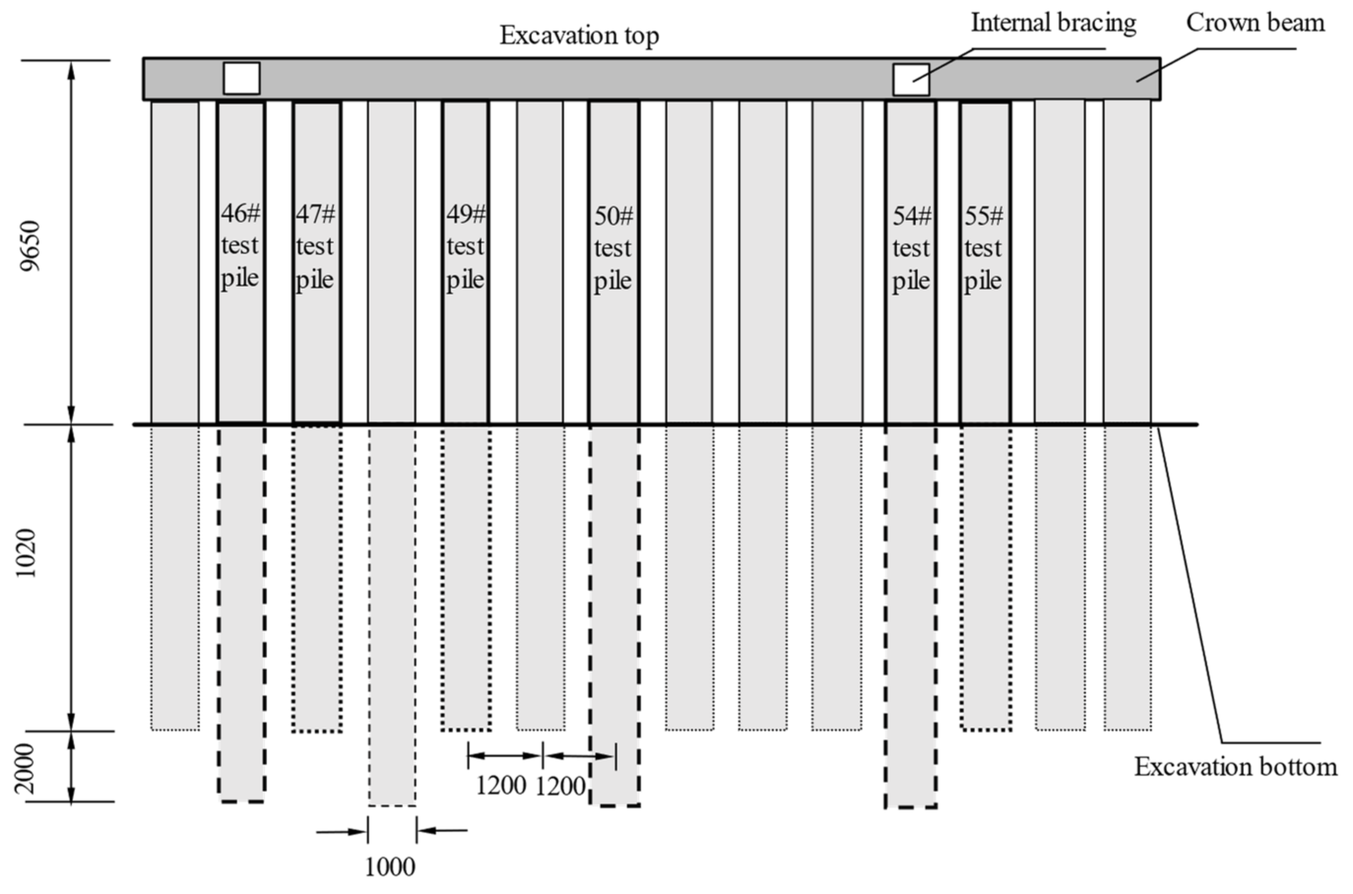
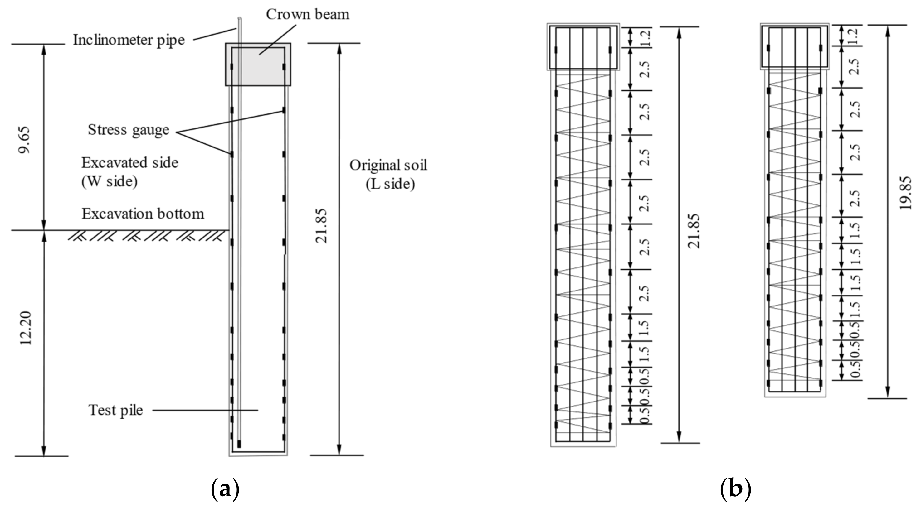
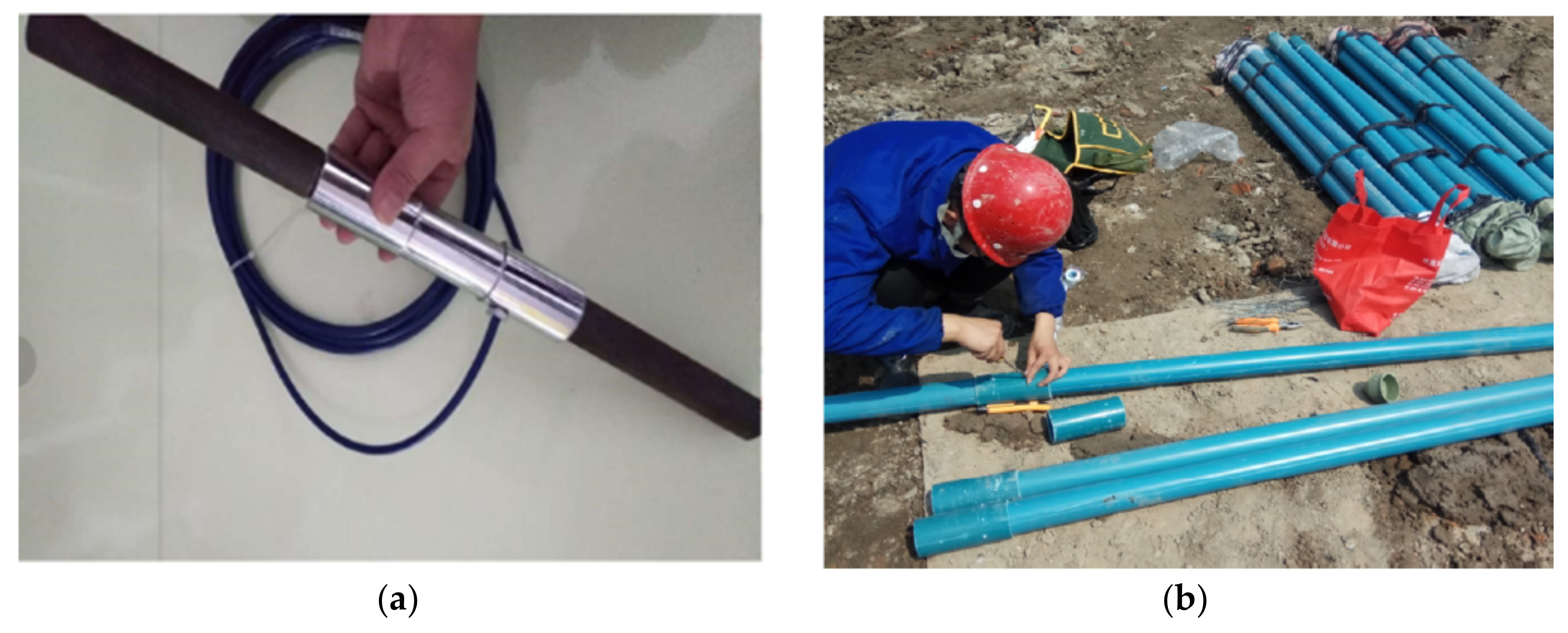
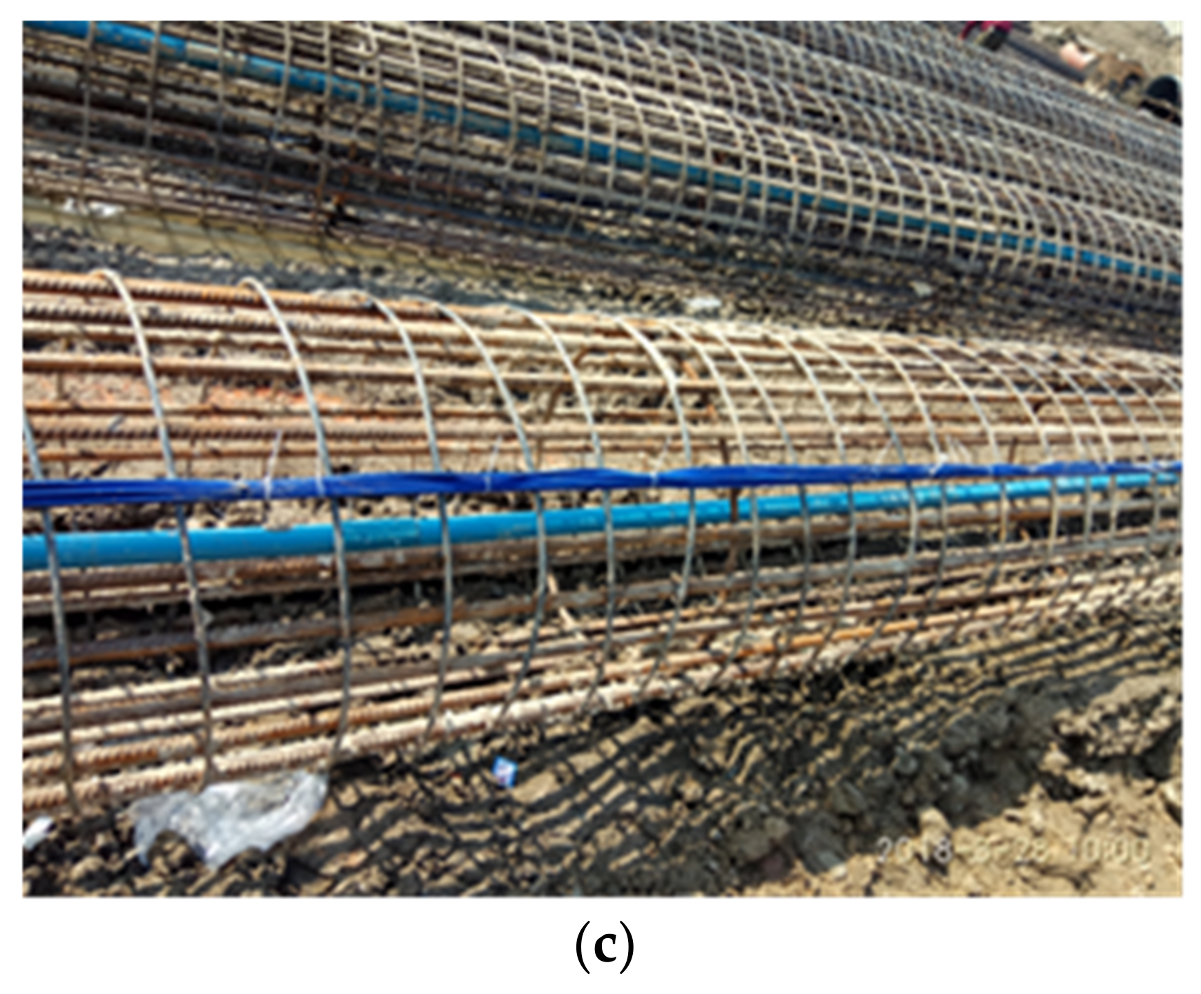
2.2. Field Test Scheme Design

According to the excavation supporting design data, a test area is set at the retaining pile on the side of plot B04 considering the influence of the surrounding environment and construction conditions. There were 13 piles in the test area, which were arranged according to the combination form of long piles and short piles, i.e., long-short pile (combination 3), long-double-short pile (combination 3), and long-triple-short pile (combination 3). Six were selected as test piles, numbered as 46#, 47#, 49#, 51#, 54#, and 55#. Figure 3 and Figure 4 show the schematic layout and cross-section of piles in the test area, respectively.
A high-precision steel stress gauge (XY-GLJJ25B) and an inclinometer were used to measure the steel stress and the horizontal displacement of the pile. In the test, reinforcement stress gauges were installed on the corresponding longitudinal bars on both sides of the test pile (L side and W side), and inclined pipes were bound on the longitudinal bars on the W side of the test pile, as shown in Figure 5a. Additionally, Figure 6 shows the field installation and layout of the stress gauge and inclinometer tube. For the reinforcement stress collected in the test, the bending moment at any cross-section of the pile body can be approximated by Equation (1).
M = E c E s × I 0 d s ( σ w σ n )
where M is the bending moment of the pile; Ec is the elastic modulus of concrete; Es is the elastic modulus of steel bar; I0 is the moment of inertia of the whole section against the neutral axis; ds is the distance between two steel bars at the same section; σ w and σ n are the stress of steel bar outside and inside of retaining pile, respectively, and with a pull as positive and pressure as negative.

3. Test Results and Analysis

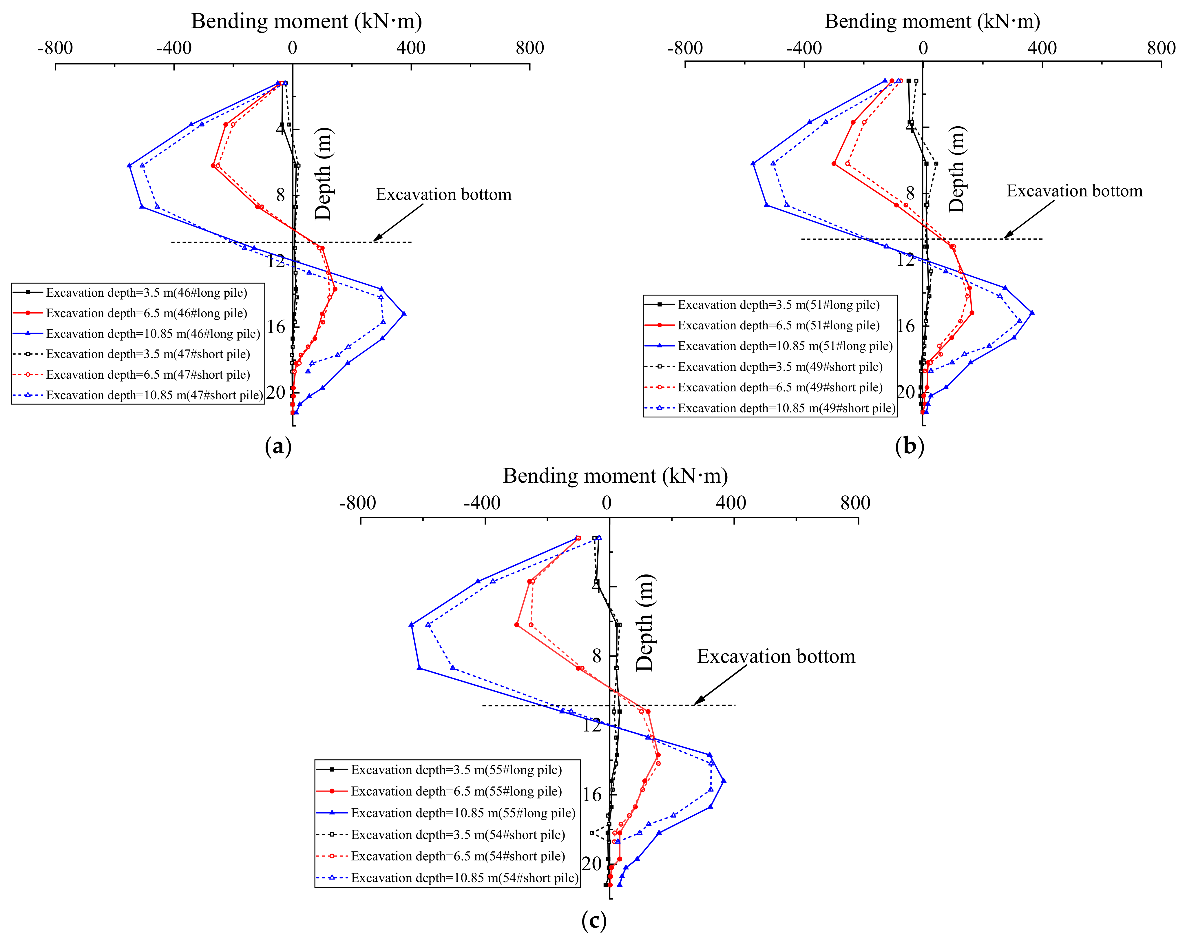
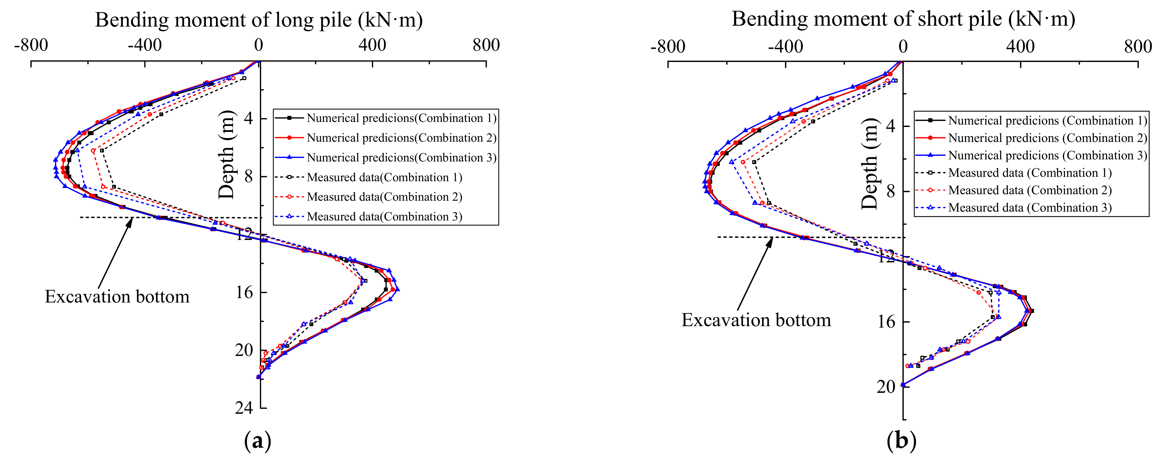
3.1. Bending Moment of the Pile under Different Excavation Depth

To understand the difference in the performance for the retaining structure in three kinds of combination, the bending moments of the piles at several different excavation depths are considered, as shown in the Figure 7. According to the figure, with the increase of excavation depth from 3.50 m to 10.85 m, the bending moment of the piles increases significantly, and the bending moment below the excavated surface decreases gradually with the increase of depth. Moreover, by comparing the contours in the Figure 7a–c, it can be found that the bending moments of long piles are only slightly greater than its counterpart of short pile at each excavation depth, when the excavation is carried out to the bottom, the maximum bending-moment of piles in the three combinations appears near the position 6.3 m from the pile top.
To further compare the deformation performance for the retaining structure in three kinds of combination, Figure 8 plots the variation curve of the bending moment with depth for the three kinds of combination. According to the figure, when the combination changes from combination 1 to 3, the peak bending moment of long pile increases from −550.3 kN·m to −637.35 kN·m. Moreover, the peak bending moment of short pile increases from −506.45 kN·m to −583.54 kN·m, and the peak moment of the long pile and short pile increases by 15.8% and 15.2%, respectively. Results from the analysis indicate that long piles bear more bending moment than short piles in the composite-retaining structure of long-short piles; the greater the number of short piles, the greater the peak bending moment of long piles and short piles in the system. It also can be seen that the increase of bending moment of long pile is greater than that of short pile when it changes from long-short pile combination to long-triple-short pile combination.

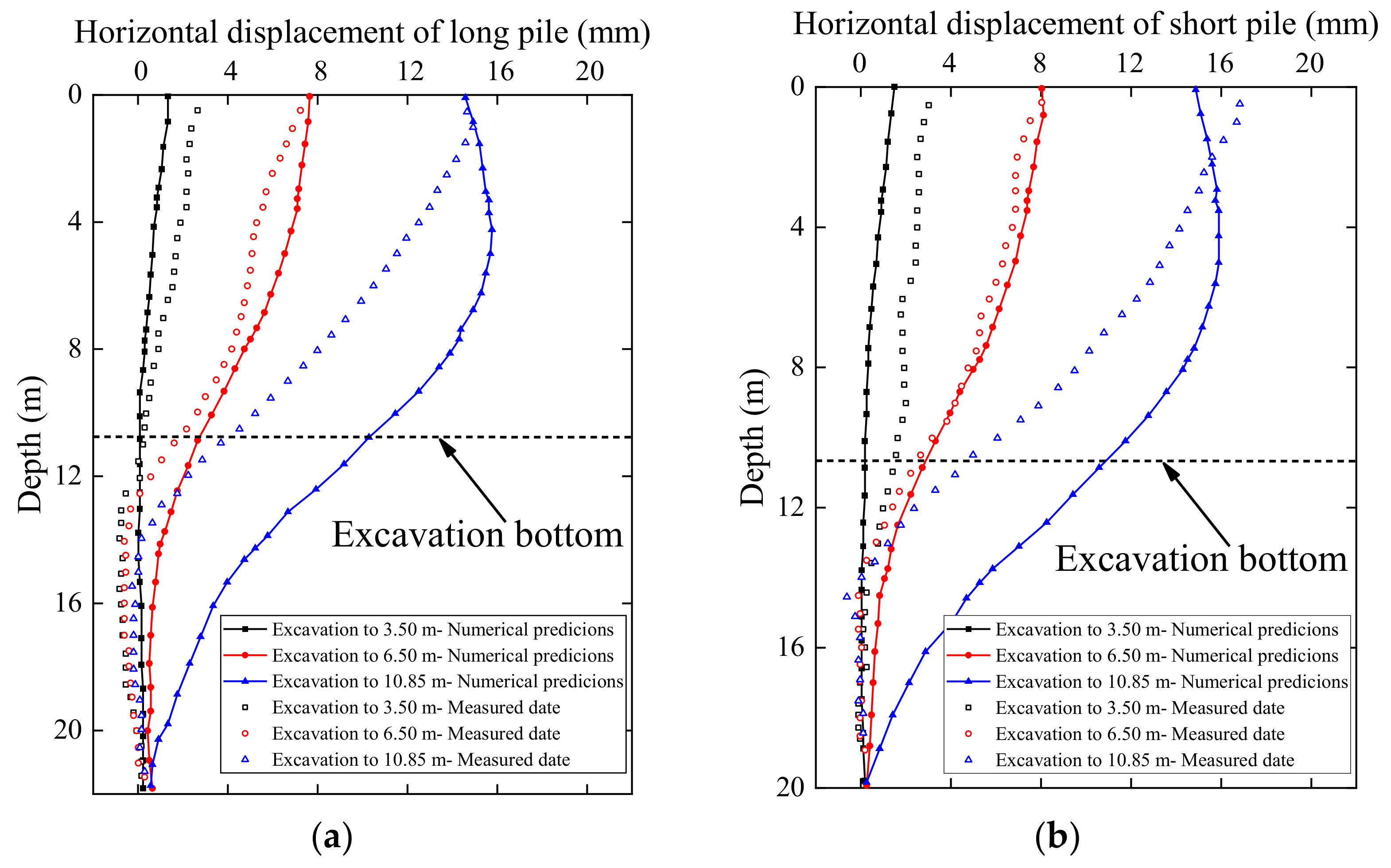
3.2. Horizontal Displacement of the Pile under Different Excavation Depth

Figure 9 shows the horizontal displacement of the piles under the three kinds of combination when the foundation pit was excavated to the bottom (as shown in Figure 10). The results show that the horizontal displacement of the pile above the excavation bottom is the most significant, and the variation trend of horizontal displacement under different combinations remains the same. Combination 3 has the largest horizontal displacement, and the peak displacement of the long pile and the short pile is 17.21 mm and 17.87 mm, respectively. Compared with combination 1, the peak displacements increased by only 9.6% and 7.9%, respectively. Furthermore, the horizontal displacement of piles under the excavation bottom has no obvious change, which is mainly because the soil under the excavation bottom is mostly gravel and argillaceous siltstone, which plays a good role in embedding the retaining piles. On the other hand, by comparing the horizontal displacements of long and short piles under the same combination in Figure 9a,b, it can be found that increasing the number of short piles does not excessively increase the horizontal displacement of piles, which is acceptable in practical engineering. As such, the maintenance combination of long and short piles can save the cost to a greater extent under the condition of exerting the bearing capacity of the piles.

4. Numerical Investigation

Although the field test can reflect the stress and deformation law of the long-short combined retaining piles in the process of excavation, it is difficult to analyze more working conditions through the full-scale experimental study due to the limitation of project schedule, time, and costs. Subsequently, further numerical studies of the pile response are performed in the PLAXIS 3D program [37].

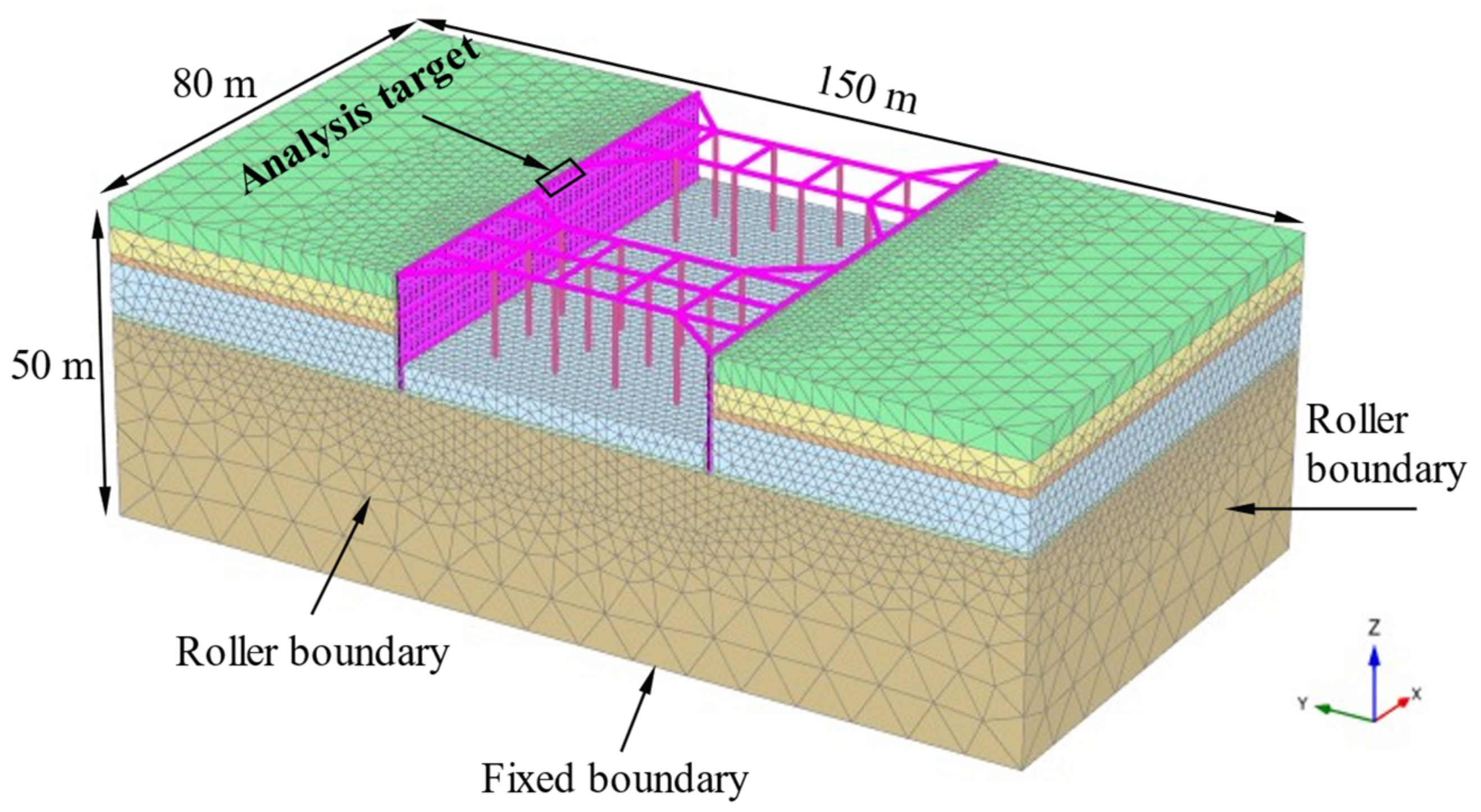
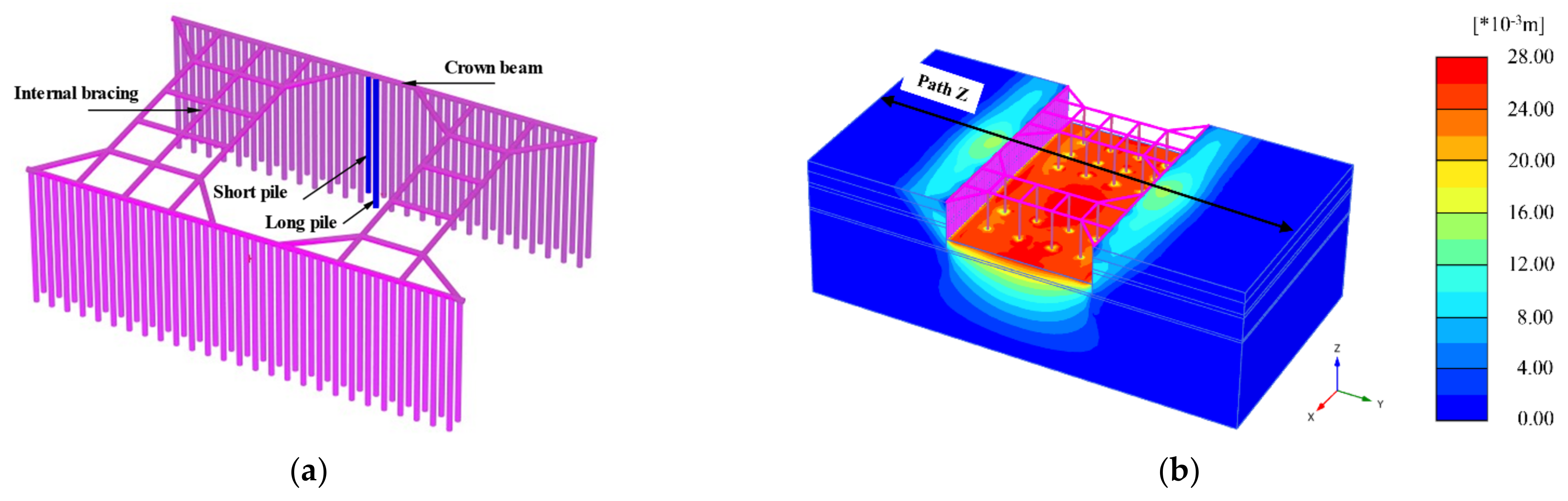
4.1. Finite Element Model

Considering the calculation cost and time, the dashed line area (B04 site) in Figure 1 was selected as the study object. Here, we set up a suitably simplified 3D finite-element model using 10-node tetrahedral elements, the model size of 150 m × 80 m × 50 m was used. Furthermore, a 6-noded isotropic-elastic-plate element was applied to the waterproof curtain (cement mixing piles); a beam element was applied to model the other system structural members such as transverse internal bracings, crown beams, and the bored pile; an embedded beam element was applied to column pile, and was assumed to behave as a linear-elastic material. The physical and mechanical parameters of retaining structures are summarized in Table 1. In addition, the contact behavior between retaining structure and soil should be simulated by the contact surface, thus, a 12-node interface element is used to simulate the interaction between soil and structure, whose behavior follows the Mohr–Coulomb model, it has been shown to be an effective method in the modeling of using PLAXIS [38,39]. The lower surface of the model is constrained in all three directions (fixed boundary), while the side surface only constrains the normal displacement (roller boundary), and the top surface is free. Figure 11 illustrates a typical excavation and 3D finite-element mesh used for analysis.
In quite a lot of geotechnical engineering, the strain range of soil is generally 0.01~0.1%, which belongs to the range of small strain. However, the soil stiffness is highly nonlinear under small strain conditions [40]. If the small strain characteristics are ignored, the stiffness of soil will be underestimated seriously, resulting in imprecise expected deformation [41]. Therefore, it is necessary to consider the stiffness characteristics of soil under the condition of small strain in the deformation analysis of excavation engineering. On the basis of the hardening soil (HS) model [42], Bens [43] incorporated the stiffness characteristics of the soil in the small strain stage, and proposed the small strain hardening model (HSS model). The HSS model has the characteristics that the shear modulus of the soil decreases with the increase of the strain and can reflect the hydrostatic pressure and dilatancy of soft clay, which is more suitable for excavation deformation analysis under sensitive environment [17,39,44,45]. In this regard, the HSS model is adopted in this paper. Based on soil samples collected on site, such parameters as the secant referential stiffness ( E 50 ref ), the tangent referential stiffness for a primary oedometer loading ( E oed ref ), the unloading/reloading referential stiffness ( E ur ref ), the small-strain shear modulus ( G 0 ref ), the failure ratio determined by triaxial drainage shear (Rf), the reference stress ( p ref ) and the modulus stress level correlation power exponent (m), and the soil strength parameter ( c , φ ) were carried out by GDS-SS-HCA hollow torsional shear instrument test system and routine consolidation apparatus. Experience values suggested by Wang et al. [44] were used for Poisson’s ratio for unloading–reloading ( ν ur ), shear strain when the shear modulus attenuation to 70% of the initial shear modulus ( γ 0.7 ), the initial resting lateral pressure coefficient ( K 0 ). Table 2 gives the parameters of HSS model, more details and explanation can be found in the work by Gu et al. [45] and Huynh et al. [46].
The method of different-group waterhead interpolation was applied to simulate the dewatering of excavation, i.e., the water table inside the excavation was progressively lowered with the excavation of the soil during each phase. Thus, in each step of excavation process, the soil group waterhead in the excavation is set as 1 m below the excavation surface, which means that the water table in the excavation drops to 1 m below the excavation surface, and the soil waterhead outside the excavation does not change, which is the natural underground water table. Table 3 shows the simulation process of excavation.

4.2. Comparison and Verification

To further verify the calculation results of the model, Figure 12 and Figure 13 show the comparison between the simulated and measured values of horizontal displacement and bending moment in combination 1, respectively.
As can be seen from Figure 12, when the excavation reaches 3.5 m and 6.5 m, the field measured results are in good agreement with the simulated results. When the excavation reaches the bottom, the simulated results are slightly greater than the measured results within a certain range from the surface. The main reasons for this difference may be temperature and the complexity of the deep soil layer. The temperature has a great influence on the monitoring instruments, which leads to some differences in the measurement result. Moreover, the actual engineering geology is more complex in this project, especially the deep soil, whereas the soil is simplified and stratified in the numerical model analysis, which is difficult to accurately reflect the engineering geology. It can be seen from Figure 13 that the measured bending moment is slightly smaller than the simulation results, while the overall change trend is basically consistent. Although there is a certain difference between the field test data and the simulation results, the difference is acceptable, thus, the numerical model can be used to predict the mechanical properties of the long-short combined retaining piles.

5. Numerical Results and Discussion

This section studies the bending moment of piles, horizontal displacement, surface settlement, and excavation bottom heave of the retaining structure under the condition of different short pile lengths. It should be pointed out that in this simulation process, the combination 1 was considered for analysis. Other parameters are described as follows: the spacing of piles and the length of long piles are selected as 0.2 m and 21.85 m, respectively, and the length of the short piles is 21.85 m, 19.85 m, 17.85 m, and 15.85 m, respectively. Figure 14 shows the pile layout under the condition that the short pile length is 19.85 m, and other working conditions are similar. During the finite element analysis, the piles marked in Figure 14a were selected for comparative analysis. Figure 14b shows the overall model displacement contour map under the condition that the short pile length is 19.85 m after reaching the bottom. Moreover, Table 4 shows the bending moment and displacement of pile control points corresponding to different short pile lengths. The bending moment of piles, horizontal displacement of piles, surface settlement, and bottom heave of the long-short combined retaining piles with different short pile lengths are compared and analyzed below.

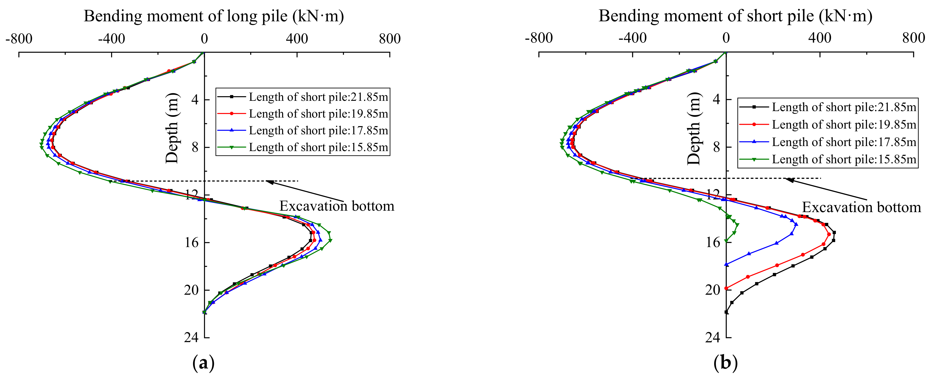
5.1. Effect of Short Pile Length

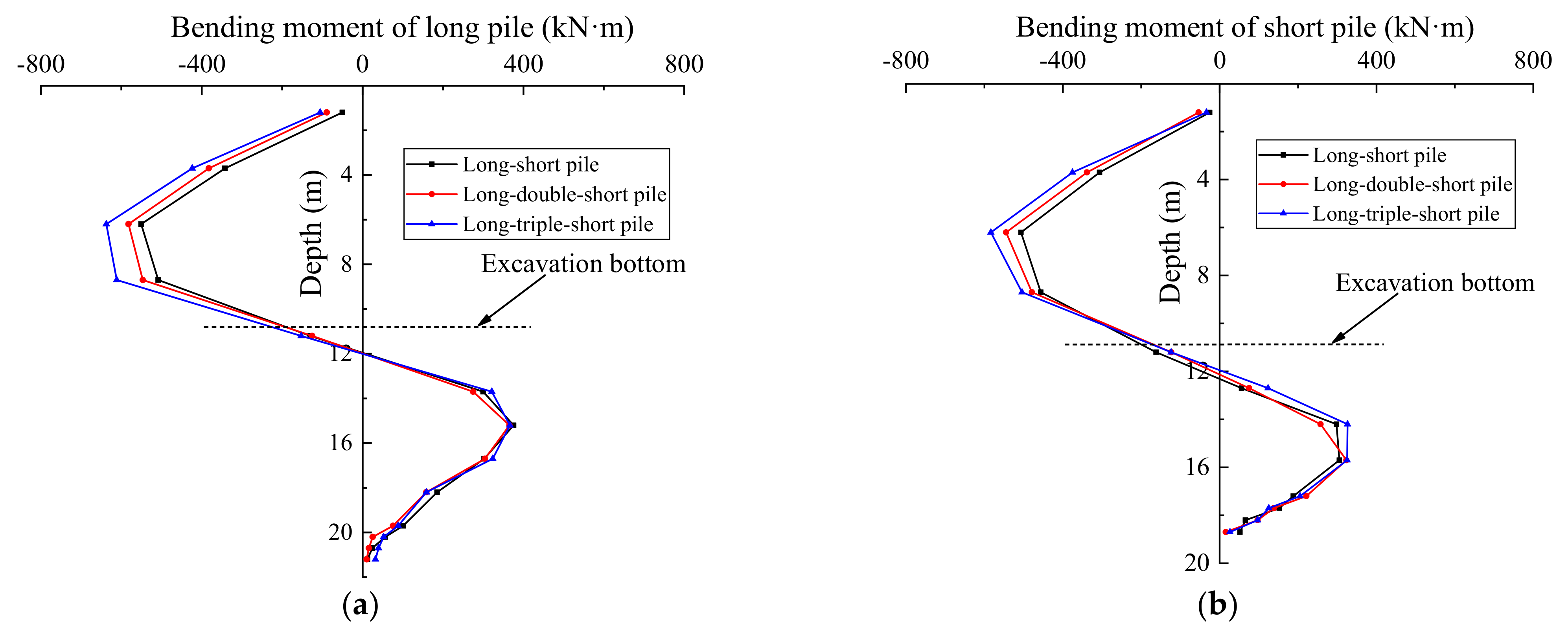
5.1.1. Bending Moment of Piles under Different Short Pile Lengths

Figure 15 shows the bending moment comparison of piles under different short pile lengths. It can be seen from the figure that the peak bending moment of the pile above the excavation bottom is larger than that below the bottom. Under different short pile lengths, the bending moment of piles changes along the direction of depth similar to the shape of “S”. When the length of the short pile is 21.85 m (the length of the long pile is equal to the short pile), the peak bending moment above and below the excavation surface is 655.2 kN·m and 438.2 kN·m, respectively. When the length of the short pile becomes 15.85 m (the length of the long pile is larger than short pile), the peak bending moment of the long pile and short pile above the excavation surface is 716.9 kN·m and 702.4 kN·m respectively, and the bending moment increases by 9.42% and 7.20%, respectively; the peak bending moment of long pile and short pile below excavation surface is 543.8 kN·m and 47.3 kN·m, respectively, and the bending moment of the long pile increases by 24.10%, while that of short pile decreases by 89.21%. It can be seen that reducing short pile length will increase the bending moment of the long and short pile to a certain extent; however, the bending moment of short piles in retaining structure decreases significantly below the excavation bottom. Therefore, in the design of the excavation retaining structure, the peak bending moment above the excavation surface is usually used as the control bending moment to choose the layout of the steel bar.

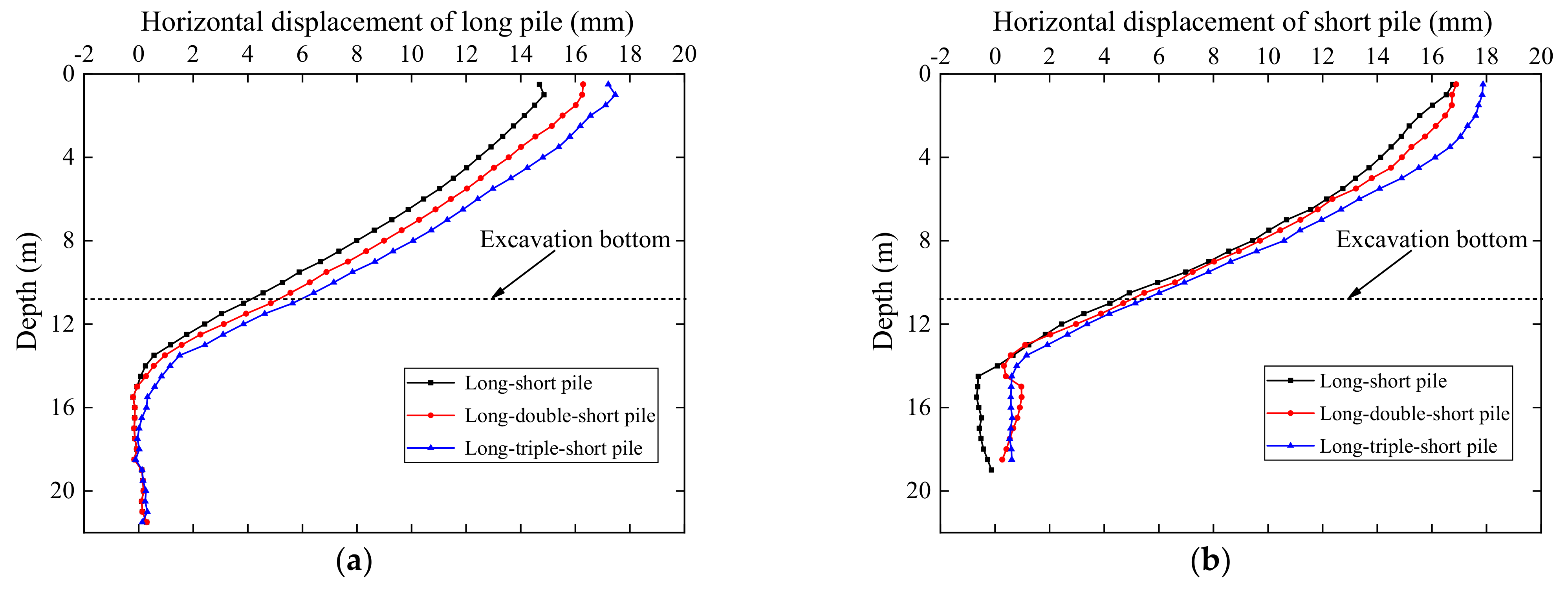
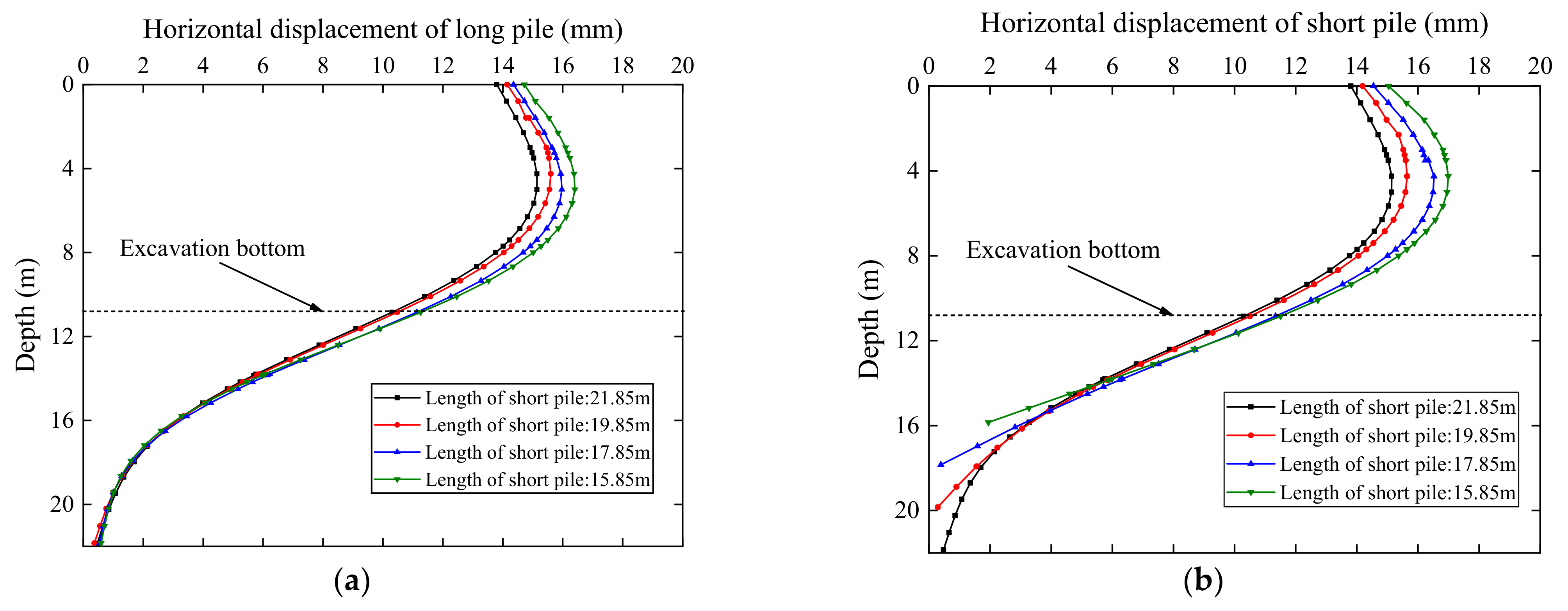
5.1.2. Horizontal Displacement under Different Short Pile Lengths

Figure 16 shows the horizontal displacement comparison curves of piles with different short pile lengths. It can be seen from the figure that the horizontal displacements of different short pile lengths have similar distribution trends along the depth direction, and the horizontal displacements of piles above the excavation are significantly larger than those below the excavation bottom. When the length of the short pile is 21.85 m, the peak horizontal displacement of the pile reaches 15.100 mm. When the length of the short pile is 15.85 m, the peak horizontal displacements of the long pile and short pile in the retaining structure are 16.402 mm and 16.991 mm, respectively, and the horizontal displacements increase by 8.62% and 12.52%. The results show that when the length of short pile is reduced above the excavation, the peak horizontal displacement of the long pile and short pile increases, and the increment of short pile displacement is larger than the long pile, they have a similar trend of horizontal displacement. However, for the excavation bottom, reducing the short pile length has no significant effect on the horizontal displacement of the long and short piles. It is shown that the selection of long-short pile combination mainly depends on the deformation behavior of piles above the excavation bottom.

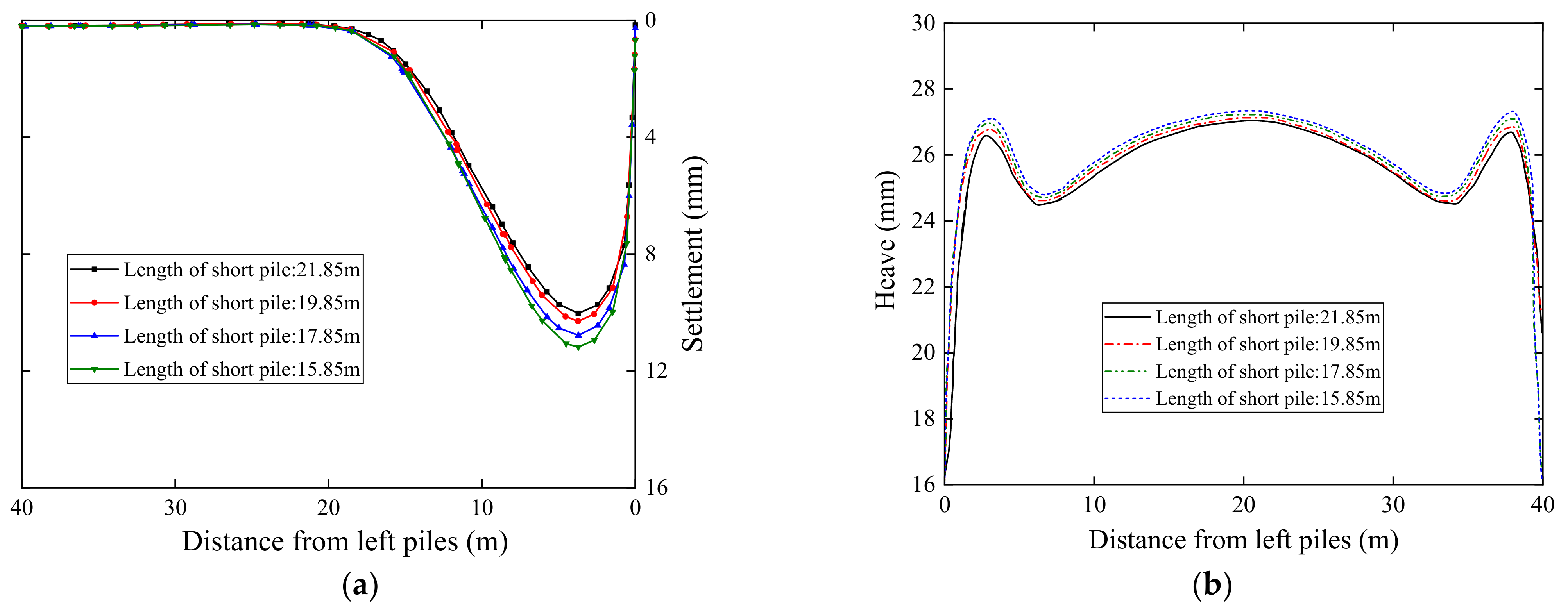
5.1.3. Surface Settlement and Excavation Bottom Heave under Different Short Pile Lengths

Excavation of foundation pit is an unloading process, and the deep stress changes greatly, which will inevitably cause the rebound deformation of excavation ground soil. In order to analyze the influence of short pile lengths on surface settlement and excavation bottom heave, the longitudinal section in the path Z direction as shown in Figure 14b is selected for comparative analysis. Figure 17a shows the surface settlement curve of surface soil within 40 m from the excavation along the Z direction of the path. As can be seen from the figures, the surface settlement within 20 m away from the excavation increases slightly with the decrease of short pile length, and the peak surface settlement is around 3.5 m away from the excavation. In contrast, the surface settlement is basically unaffected beyond 20 m of the excavation edge. When the length of the short pile is 21.85 m, the peak surface settlement is 10.025 mm, when the length of the short pile is 19.85 m, 17.85 m, and 15.85 m, the peak surface settlement is 10.300 mm, 10.781 mm, and 11.178 mm, with growth rates of 2.74%, 7.54%, and 11.50%, respectively. The results show that when the length of the short pile is reduced locally, the influence of the short pile length on the surface settlement is not worthy of consideration.
Figure 17b shows the heave curves of the pit bottom along the Z direction under different short pile lengths. It can be seen from the figure that with the decrease of short pile length, the heave of excavation bottom also increased slightly, but the change was not significant. When the short pile length is 21.85 m, the heave at about 3.0 m away from the pit edge is 26.14 mm, and the heave in the middle of the excavation bottom is 27.11 mm, when the length of the short pile is 15.85 m, the heave at about 3.0 m away from the excavation is 27.31 mm, and the heave in the middle of the excavation bottom is 27.37 mm, with growth rates of 4.48% and 0.96%, respectively. It can be seen that the heave growth of the bottom near the two sides of the excavation is greater than the middle, but in general, the uplift growth is not significant.

5.2. Effect of Pile Spacing

In this section, combination 1 is taken as the object, the length of the long pile and the short pile is 21.85 m and 17.85 m, respectively, and the bending moment of piles, horizontal displacement of piles, surface settlement, and excavation bottom heave are studied under three different pile spacing (0.2 m, 0.25 m, and 0.3 m) of the long-short combined retaining piles (the analysis does not consider removing the internal bracing, and the spacing here refers to the distance of the outer surfaces between adjacent piles).

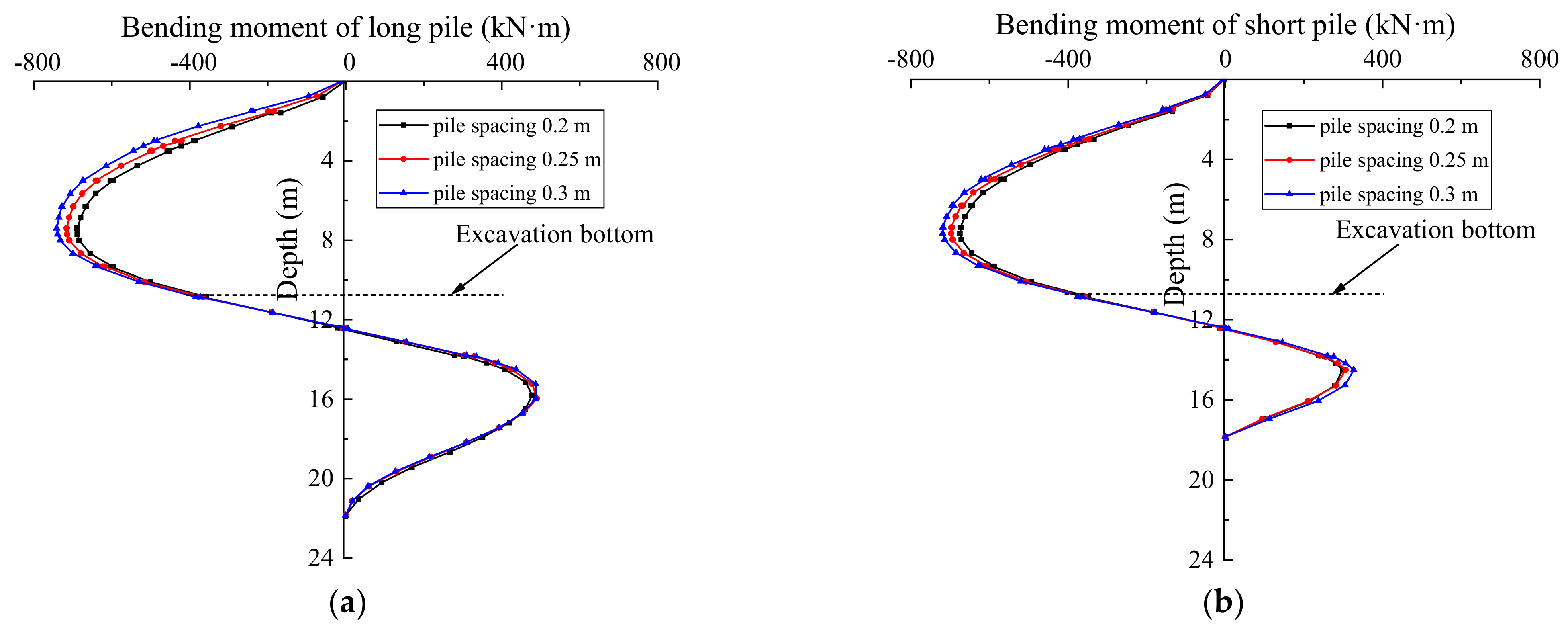
5.2.1. Bending Moment of Piles under Different Pile Spacing

Figure 18 shows the comparison of the bending moment under different pile spacing. As it can be seen from the figure, the peak bending moment of the pile above the excavation bottom is larger than that below the bottom. Under different pile spacing, the bending moment of piles changes along the direction of depth similar to the shape of “S”, while the bending moment below the bottom of the foundation pit does not change significantly. When the pile spacing is 0.2 m, the peak bending moment of the long pile and short pile is 689.2 kN·m and 675.1 kN·m, respectively. When the pile spacing increases to 0.3 m, the peak bending moments of the long pile and short pile are 741.2 kN·m and 719.3 kN·m, with growth rates of 7.54% and 6.55%, respectively. The results show that with the increase of pile spacing, the bending moment of both long pile and short pile above excavation bottom increases significantly, and the increase of bending moment of the long pile is greater than the short pile. As the external load of retaining piles remains unchanged, when the pile spacing increases, the number of retaining piles on the side wall of excavation decreases, resulting in the redistribution of earth pressure acting on the pile body, increase of earth pressure borne by single pile, and increase of earth pressure transmitted to the long pile. It can be seen that the change of pile spacing has a significant influence on the bending moment of the long-short combined retaining piles above the excavation face.

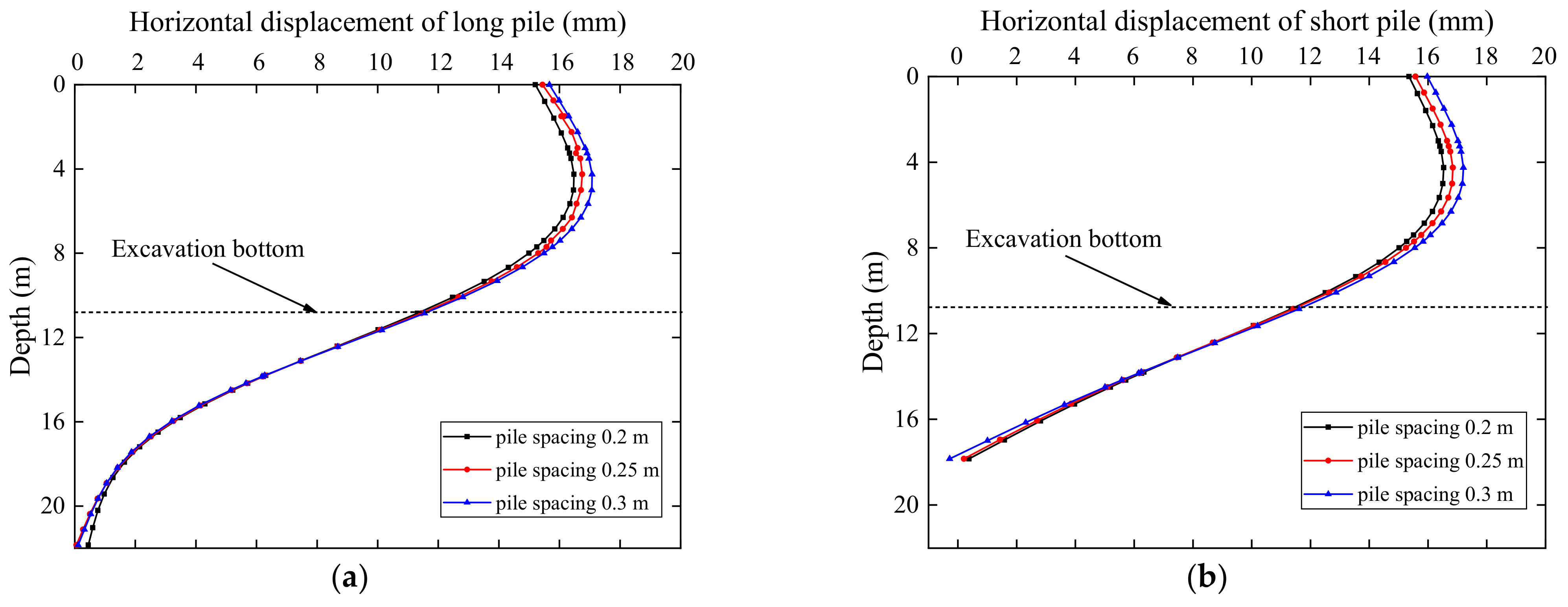
5.2.2. Horizontal Displacement under Different Pile Spacing

Figure 19 shows the horizontal displacement of piles under different pile spacing. It can be seen from the figure that the horizontal displacement under different pile spacing has a similar change trend along the depth direction, and the horizontal displacement of pile above excavation bottom is significantly greater than that below excavation bottom. When the pile spacing is 0.2 m, the horizontal displacement peaks of the long pile and short pile in the retaining structure are 16.48 mm and 16.53 mm, respectively. When the pile spacing increases to 0.25 m, the horizontal displacement peaks of long pile and short pile are 16.76 mm and 16.82 mm, respectively, increasing by 1.70% and 3.09%. When the pile spacing continues to increase to 0.3 m, the horizontal displacement peaks of the long pile and short pile only increase by 3.64% and 4.11%, respectively, compared with the pile spacing 0.25 m. The results show that with the increase of pile spacing, the horizontal displacement peaks of both long pile and short pile increase slightly, and the displacement of the short pile increases more than that of the long pile. The effect of pile spacing on horizontal displacement is mainly above the excavation bottom.

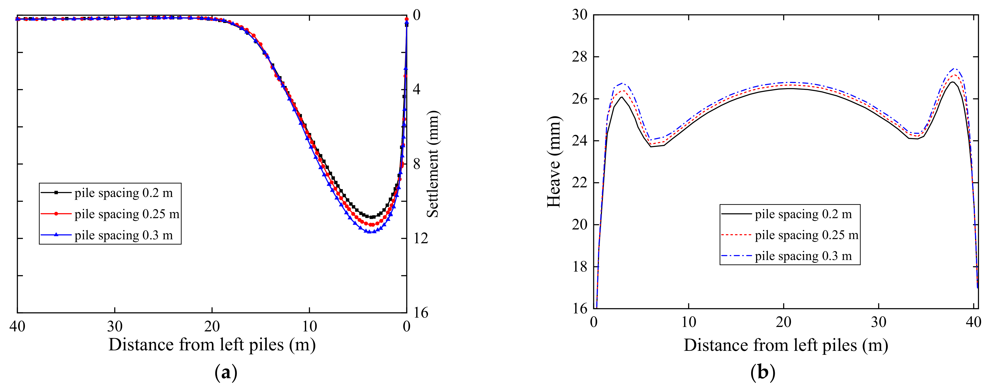
5.2.3. Surface Settlement and Heave of Excavation Bottom under Different Pile Spacing

In order to study the influence of pile spacing on surface settlement and excavation bottom heave, the longitudinal section in the path Z direction in Figure 14b was selected for analysis, and Figure 20a is the surface settlement curve along the path Z direction on the left side of the excavation. According to the figure, when the short pile spacing is 0.2 m, the peak surface settlement is 10.8 mm, when pile spacing increases from 0.2 m to 0.25 m and 0.3 m, the maximum surface settlement is 11.26 mm and 11.46 mm, respectively, increasing by 1.26% and 6.11%. The results show that the surface settlement near the excavation edge increases slightly with the increase of pile spacing. The increase of horizontal displacement caused by the increase of pile spacing may be an important reason for the increase of surface settlement near the long-short combined retaining piles. It is worth noting that the surface settlement is most significant in the area about 3 m away from the excavation edge, and the surface settlement is basically not affected by the change of pile spacing beyond 20 m away from the excavation edge. Consequently, the influence of pile spacing on surface settlement is almost ignored within a reasonable range of pile spacing.
Figure 20b shows the heave curves of the excavation bottom along the Z direction for different pile spacing. It can be seen from the figure that with the increase of pile spacing, the heave of the excavation bottom increases slightly, and the heave of the excavation bottom near the two sides of the excavation increases more than the central part. In general, the increase of pile spacing has little effect on the heave of excavation bottom.

6. Conclusions

Based on the actual deep excavation engineering, the field tests of three combinations of the long-short combined retaining piles (long-short pile, long-double-short pile and long-triple-short pile) were carried out, and the numerical simulation of the test area was also investigated by using finite element program. According to the discussion of measured and simulation results, the following conclusions can be preliminarily drawn:
  • In the long-short combined retaining piles, long piles share more bending moment than short piles; the larger the number of short piles, the larger the bending moment of long piles and short piles, when the combination changes from combination 1 to 3, the peak bending moment of the long pile and short pile increases by 15.8% and 15.2%, respectively.
  • The maximum displacement is near the pile top, combination 3 has the largest horizontal displacement, and the peak displacement of the long pile and the short pile is 17.21 mm and 17.87 mm, respectively, but almost no effect exists on the horizontal displacement below the excavation bottom. Disregarding the combination for the long and short piles, the horizontal displacements between long and short piles have few gaps.
  • Generally speaking, the influence of short pile length and pile spacing on surface settlement and excavation bottom uplift can be ignored.
  • In the retaining structure of long-short pile, the bending moment and horizontal displacement of long and short piles will be increased to a certain extent by decreasing the short pile length and increasing the pile spacing, and this phenomenon is mainly concentrated above the excavation bottom. Therefore, the length of the short pile, the ratio of the short pile and pile spacing can be appropriately reduced to save the project cost on the premise that the bending moment and deformation of pile meet the engineering requirements.
It is worth mentioning that the research of this paper is mainly aimed at three kinds of long and short pile combinations and the effects of pile length and pile spacing were analyzed. Based on the above analysis results, it is further confirmed that it is feasible to reduce part of the pile length in the pile retaining structure, which is a novel support system with sufficient safety and saves capital investment. However, the influence of the long-short piles composite structures on the surrounding underground structure is still largely unknown, which will be further studied in the subsequent study.

Author Contributions

Conceptualization, H.Z., B.Z. and C.X.; methodology, H.Z. and B.Z.; software, H.Z., W.L. and C.X.; analysis, investigation, H.Z. and C.X.; data curation, H.Z., D.G., B.Z. and W.L.; writing—original draft preparation, H.Z. and D.G.; writing—review and editing, H.Z., B.Z. and C.X.; supervision, B.Z. and C.X. All authors have read and agreed to the published version of the manuscript.

Funding

The authors are very grateful for the support from the National Science Fund for Distinguished Young Scholars (No. 51725802) and the National Natural Science Foundation of China (No. 41972291, No. 5202010500).

Institutional Review Board Statement

Not applicable.

Informed Consent Statement

Not applicable.

Data Availability Statement

Not applicable.

Conflicts of Interest

The authors declare no conflict of interest.

Abbreviations

c cohesion;
dsdistance between two steel bars at the same section;
Ecelastic modulus of concrete;
Eselastic modulus of steel bar;
E 50 ref secant referential stiffness;
E ur ref unloading/reloading referential stiffness;
E oed ref tangent referential stiffness for a primary oedometer loading;
G 0 ref small-strain shear modulus;
I0moment of inertia of the whole section against the neutral axis;
K 0 initial resting lateral pressure coefficient;
Mbending moment of the pile;
mmodulus stress level correlation power exponent;
p ref reference stress;
R f failure ratio determined by triaxial drainage shear;
φ friction angle;
γ soil unit weight;
γ 0.7 shear strain when the shear modulus attenuation to 70% of the initial shear modulus;
v ur Poisson’s ratio;
σ w stress of steel bar outside of retaining pile;
σ n stress of steel bar inside of retaining pile.

References

  1. Tan, Y.; Li, M.W. Measured performance of a 26 m deep top-down excavation in downtown Shanghai. Can. Geotech. J. 2011, 48, 704–719. [Google Scholar] [CrossRef]
  2. Cheng, K.; Xu, R.Q.; Ying, H.W.; Gan, X.L.; Zhang, L.S.; Liu, S.J. Observed performance of a 30.2 m deep-large basement excavation in Hangzhou soft clay. Tunn. Undergr. Space Technol. 2021, 111, 103872. [Google Scholar] [CrossRef]
  3. Lim, A.; Ou, C.Y. Performance and three-dimensional analyses of a wide excavation in soft soil with strut-free retaining system. Int. J. Geomech. 2018, 18, 05018007. [Google Scholar] [CrossRef]
  4. Lim, A.; Ou, C.Y.; Hsieh, P.G. A novel strut-free retaining wall system for deep excavation in soft clay: Numerical study. Acta Geotech. 2020, 15, 1557–1576. [Google Scholar] [CrossRef]
  5. Liu, T.Y.; Ho, S.J.; Tserng, H.P.; Tzou, H.K. Using a unique retaining method for building foundation excavation: A case study on sustainable construction methods and circular economy. Buildings 2022, 12, 298. [Google Scholar] [CrossRef]
  6. Farzi, M.; Pakbaz, M.S.; Aminpour, H.A. Selection of support system for urban deep excavations: A case study in Ahvaz geology. Case Stud. Constr. Mater. 2018, 8, 131–138. [Google Scholar] [CrossRef]
  7. Gil-Martín, L.M.; Hernández-Montes, E.; Shin, M.; Aschheim, M. Developments in excavation bracing systems. Tunn. Undergr. Space Technol. 2012, 31, 107–116. [Google Scholar] [CrossRef]
  8. Moormann, C. Analysis of wall and ground movements due to deep excavations in soft soil based on a new worldwide database. Soils Found. 2004, 44, 87–98. [Google Scholar] [CrossRef]
  9. Tan, Y.; Wei, B. Observed behaviors of a long and deep excavation constructed by cut-and-cover technique in shanghai soft clay. J. Geotech. Geoenviron. Eng. 2012, 138, 69–88. [Google Scholar] [CrossRef]
  10. Dong, Y.P.; Burd, H.J.; Houlsby, G.T. Finite-element analysis of a deep excavation case history. Géotechnique 2016, 66, 1–15. [Google Scholar] [CrossRef]
  11. Chen, H.H.; Li, J.P.; Yang, C.Y.; Feng, C. A theoretical study on ground surface settlement induced by a braced deep excavation. Eur. J. Environ. Civ. Eng. 2020, 26, 1897–1916. [Google Scholar] [CrossRef]
  12. Ying, H.W.; Cheng, K.; Liu, S.J.; Xu, R.Q.; Lin, C.G.; Zhu, C.W.; Gan, X.L. An efficient method for evaluating the ground surface settlement of Hangzhou metro deep basement considering the excavation process. Acta Geotech. 2022, 1–13. [Google Scholar] [CrossRef]
  13. Ding, Y.C.; Zhou, S.X.; Wang, J.H. Three-dimensional numerical analysis of soil nailing for deep excavation. J. Shanghai Jiaotong Univ. 2011, 45, 547–552. (In Chinese) [Google Scholar]
  14. Zolqadr, E.; Yasrobi, S.S.; Norouz Olyaei, M. Analysis of soil nail walls performance—Case study. Geomech. Geoengin. 2016, 11, 1–12. [Google Scholar] [CrossRef]
  15. Chavan, D.; Mondal, G.; Prashant, A. Seismic analysis of nailed soil slope considering interface effects. Soil Dyn. Earthq. Eng. 2017, 100, 480–491. [Google Scholar] [CrossRef]
  16. Zhang, M.; Wang, X.H.; Yang, G.C.; Wang, Y. Numerical investigation of the convex effect on the behavior of crossing excavations. J. Zhejiang Univ. Sci. A 2011, 12, 747–757. [Google Scholar] [CrossRef]
  17. Xu, C.J.; Yang, K.F.; Fan, X.Z.; Ge, J.J.; Jin, L. Numerical investigation on instability of buildings caused by adjacent deep excavation. J. Perform. Constr. Facil. 2021, 35, 04021040. [Google Scholar] [CrossRef]
  18. Hong, S.H.; Lee, F.H.; Yong, K.Y. Three-dimensional pile-soil interaction in soldier-piled excavations. Comput. Geotech. 2003, 30, 81–107. [Google Scholar] [CrossRef]
  19. Cheng, X.S.; Zheng, G.; Diao, Y.; Huang, T.M.; Deng, C.H.; Lei, Y.W.; Zhou, H.Z. Study of the progressive collapse mechanism of excavations retained by cantilever contiguous piles. Eng. Fail. Anal. 2017, 71, 72–89. [Google Scholar] [CrossRef]
  20. Hassiotis, S.; Chameau, J.L.; Gunaratne, M. Design method for stabilization of slopes with piles. J. Geotech. Geoenviron. Eng. 1997, 123, 314–323. [Google Scholar] [CrossRef]
  21. Guo, W.D.; Lee, F.H. Load transfer approach for laterally loaded piles. Int. J. Numer. Anal. Methods Geomech. 2001, 25, 1101–1129. [Google Scholar] [CrossRef]
  22. Basu, D.; Salgado, R.; Prezzi, M.A. Continuum-based model for analysis of laterally loaded piles in layered soils. Géotechnique 2009, 59, 127–140. [Google Scholar] [CrossRef]
  23. Liang, F.Y.; Li, Y.C.; Li, L.; Wang, J.L. Analytical solution for laterally loaded long piles based on Fourier–Laplace integral. Appl. Math. Model. 2014, 38, 5198–5216. [Google Scholar] [CrossRef]
  24. Wong, S.C.; Poulos, H.G. Approximate pile-to-pile interaction factors between two dissimilar piles. Comput. Geotech. 2005, 32, 613–618. [Google Scholar] [CrossRef]
  25. Liyanapathirana, D.S.; Nishanthan, R. Influence of deep excavation induced ground movements on adjacent piles. Tunn. Undergr. Space Technol. 2016, 52, 168–181. [Google Scholar] [CrossRef]
  26. Cui, X.Y.; Ye, M.G.; Zhuang, Y. Performance of a foundation pit supported by bored piles and steel struts: A case study. Soils Found. 2018, 58, 1016–1027. [Google Scholar] [CrossRef]
  27. Chen, A.; Wang, Q.; Chen, Z.D.; Chen, J.P.; Chen, Z.; Yang, J.G. Investigating pile anchor support system for deep foundation pit in a congested area of Changchun. Bull. Eng. Geol. Environ. 2021, 80, 1125–1136. [Google Scholar] [CrossRef]
  28. Zhang, C.L.; Su, L.J.; Chen, W.Z.; Jiang, G.L. Full-scale performance testing of bored piles with retaining walls in high cutting slope. Transp. Geotech. 2021, 29, 100563. [Google Scholar] [CrossRef]
  29. Leung, C.F.; Chow, Y.K.; Shen, R.F. Behavior of pile subject to excavation-induced soil movement. J. Geotech. Geoenvironmental Eng. 2000, 126, 947–954. [Google Scholar] [CrossRef]
  30. Zhang, R.J.; Zheng, J.J.; Pu, H.F.; Zhang, L.M. Analysis of excavation-induced responses of loaded pile foundations considering unloading effect. Tunn. Undergr. Space Technol. 2011, 26, 320–335. [Google Scholar] [CrossRef]
  31. Yang, H. Research on the Working Performance and Designing Problem of the Long-Short Pile Foundation. Ph.D. Thesis, Tongji University, Shanghai, China, 2006. [Google Scholar]
  32. Zhao, M.H.; Zhang, L.; Yang, M.H. Settlement calculation for long-short composite piled raft foundation. J. Cent. South Univ. 2006, 13, 749–754. [Google Scholar] [CrossRef]
  33. Guo, Y.C.; Lv, C.Y.; Hou, S.Q.; Liu, Y.L.; Garcea, G. Experimental study on the pile-soil synergistic mechanism of composite foundation with rigid long and short piles. Math. Probl. Eng. 2021, 2021, 6657116. [Google Scholar] [CrossRef]
  34. Zheng, G.; Cheng, X.S. Experimental study on cantilever contiguous retaining piles with different lengths. Chin. J. Geotech. Eng. 2008, 30, 410–415. (In Chinese) [Google Scholar]
  35. Xu, C.J.; Xu, Y.L.; Sun, H.L. Application of long-short pile retaining system in braced excavation. Int. J. Civ. Eng. 2015, 13, 81–89. [Google Scholar]
  36. Xu, C.J.; Ding, H.B.; Luo, W.J.; Tong, L.H.; Chen, Q.S.; Deng, J.L. Experimental and numerical study on performance of long-short combined retaining. Geomech. Eng. 2020, 20, 255–265. [Google Scholar] [CrossRef]
  37. Brinkgreve, R.B.J.; Kumarswamy, S.; Swolfs, W.M.; Waterman, D.; Chesaru, A.; Bonnier, P.G. PLAXIS 2016; Brinkgreve Delft University of Technology & PLAXIS bv: Delft, The Netherlands, 2016. [Google Scholar]
  38. Chheng, C.; Likitlersuang, S. Underground excavation behaviour in Bangkok using three-dimensional finite element method. Comput. Geotech. 2018, 95, 68–81. [Google Scholar] [CrossRef]
  39. Nejjar, K.; Dias, D.; Cuira, F.; Chapron, G.; Le Bissonnais, H. Numerical modelling of a 32 m deep excavation in the suburbs of Paris. Eng. Struct. 2022, 268, 114727. [Google Scholar] [CrossRef]
  40. Clayton, C.R.I. Stiffness at small strain: Research and practice. Géotechnique 2011, 61, 5–37. [Google Scholar] [CrossRef]
  41. Gu, X.Q.; Lu, L.T.; Li, X.W.; Ju, S.W. Experimental study of small strain stiffness properties of soil. J. Tongji Univ. 2018, 46, 312–317. (In Chinese) [Google Scholar]
  42. Schanz, T.; Vermeer, P.A.; Bonnier, P.G. The hardening soil model-formulation and verification. In Beyond 2000 in Computational Geotechnics 1999; Balkema: Amsterdam, The Netherlands, 2019; pp. 281–296. [Google Scholar]
  43. Benz, T. Small-Strain Stiffness of Soils and Its Numerical Consequences. Ph.D. Thesis, University of Stuttgart, Stuttgart, Germany, 2007. [Google Scholar]
  44. Wang, W.D.; Wang, H.R.; Xu, Z.H. Study of parameters of HS-Small model used in numerical analysis of excavations in Shanghai area. Rock Soil Mech. 2013, 34, 1766–1774. (In Chinese) [Google Scholar]
  45. Gu, X.Q.; Wu, R.T.; Liang, F.Y.; Gao, G.Y. On HSS model parameters for Shanghai soils with engineering verification. Rock Soil Mech. 2021, 42, 833–845. (In Chinese) [Google Scholar]
  46. Huynh, Q.T.; Lai, V.Q.; Boonyatee, T.; Keawsawasvong, S. Verification of soil parameters of hardening soil model with small-strain stiffness for deep excavations in medium dense sand in Ho Chi Minh City, Vietnam. Innov. Infrastruct. Solut. 2022, 7, 15. [Google Scholar] [CrossRef]
Figure 1. Schematic diagram of the excavation plane position in the field test.
Buildings 12 01524 g001
Figure 2. Schematic diagram of the profile of area B04 support system.
Buildings 12 01524 g002
Figure 3. Schematic diagram of working condition layout in the field test site.
Buildings 12 01524 g003
Figure 4. The schematic cross-section of the test pile (unit: mm).
Buildings 12 01524 g004
Figure 5. Schematic diagram of retaining pile stress gauge and inclined pipe layout (unit: m): (a) inclinometer tube and stress gauge arrangement; (b) stress gauge installation position.
Buildings 12 01524 g005
Figure 6. Site layout of stress gauge and inclinometer tube: (a) stress meter; (b) inclinometer tube. (c) reinforcement cage.
Buildings 12 01524 g006aBuildings 12 01524 g006b
Figure 7. Bending moment of the pile during excavation: (a) combination 1; (b) combination 2; (c) combination 3.
Buildings 12 01524 g007
Figure 8. Bending moment of the pile after excavation to 10.85 m: (a) long pile; (b) short pile.
Buildings 12 01524 g008
Figure 9. Horizontal displacement of long and short piles when excavated to the excavation bottom: (a) long pile; (b) short pile.
Buildings 12 01524 g009
Figure 10. Photo of the site excavation to the bottom.
Buildings 12 01524 g010
Figure 11. Example of mesh employed in the FE analyses.
Buildings 12 01524 g011
Figure 12. Comparison of measured horizontal displacement and numerical results (combination 1): (a) long pile; (b) short pile.
Buildings 12 01524 g012
Figure 13. Comparison between simulation results and measured results of bending moment: (a) long pile; (b) short pile.
Buildings 12 01524 g013
Figure 14. Layout form and the calculation result of combination 1: (a) The pile layout under the condition that the short pile length is 19.85 m; (b) the overall model displacement contour map.
Buildings 12 01524 g014
Figure 15. Bending moment of piles under different short pile lengths: (a) long pile; (b) short pile.
Buildings 12 01524 g015
Figure 16. Horizontal displacement of piles under different short pile lengths: (a) long pile; (b) short pile.
Buildings 12 01524 g016
Figure 17. Settlement curve of surface soil and uplift curve of the bottom of excavation: (a) surface settlement curve; (b) heave curve.
Buildings 12 01524 g017
Figure 18. Bending moment of the pile at different spacing: (a) long pile; (b) short pile.
Buildings 12 01524 g018
Figure 19. Horizontal displacement of long and short piles with different spacing: (a) long pile; (b) short pile.
Buildings 12 01524 g019
Figure 20. Settlement curve of surface soil and uplift curve of the bottom of excavation: (a) surface settlement curve; (b) heave curve.
Buildings 12 01524 g020
Table 1. Physical and mechanical parameters of retaining structures.
TypeCross-Sectional Area (m2)Thickness (m)Young’s Modulus (GPa)Unit Weight (kN/m3)Poisson’s Ratio
Bored pile0.785-30240.18
Lateral bracing0.8-28240.18
Crown beam0.8-28240.18
Waterproof curtain-0.828200.18
Lattice column--20078.50.25
Column pile0.7-30230.18
Table 2. Parameters of HSS model of soil layers.
Soil Stratum c (kPa) φ ( ) γ (kN/m3)K0m ν u r E 50 r e f ( MPa ) E u r r e f ( MPa ) E o e d r e f ( MPa ) G 0 r e f ( MPa ) γ 0.7 ( / 10 4 ) R f
Clay8.629.218.000.510.80.24.838.63.88010.95
Mucky silty clay6.525.617.100.570.80.23.834.22.36010.90
Silty clay25.828.220.300.530.80.24.939.35.25010.92
Sandy silt2.036.820.500.400.80.29.159.18.010010.96
Round gravel037.320.500.450.80.226.3131.526.312010.90
Argillaceous siltstone2540.021.500.580.80.213.567.513.513510.90
Table 3. Stages of realization of the excavation.
PhaseSimulation Process
1K0 process (in order to balance initial in-situ stress)
2Reset displacement of soil, waterproof curtain construction and bored piles penetration
3Crown beam, column pile and internal bracing were created
4Excavation to −1.5 m, and lower the ground water table to −4.5 m
5Excavation to −3.5 m, and lower the ground water table to −7.5 m
6Excavation to −6.5 m, and lower the ground water table to −11.85 m
7Excavation to −10.85 m
Table 4. Bending moment and displacement at control points of long-short piles corresponding to different short pile lengths (combination 1).
ObjectLength of the Short Piles (21.85 m)Length of the Short Piles (19.85 m)Length of the Short Piles (17.85 m)Length of the Short Piles (15.85 m)
Long PileShort PileLong PileShort PileLong PileShort PileLong PileShort Pile
Bending moment (kN·m)655.2655.2673.2658.8675.1689.2716.9702.4
Displacement (mm)15.10015.10015.60115.64815.97016.52416.40216.991
Publisher’s Note: MDPI stays neutral with regard to jurisdictional claims in published maps and institutional affiliations.

