Article

Seismic Vulnerability of Masonry Lighthouses: A Study of the Bengut Lighthouse, Dellys, Boumerdès, Algeria

by
Karima Amari
1,
Amina Abdessemed Foufa
1,
Mustapha Cheikh Zouaoui
1 and
Giuseppina Uva
2,*
1
Environnement et Technologie pour l’Architecture et le Patrimoine, Institut d’architecture et d’urbanisme, Université Saad Dahleb, 0900 Blida, Algeria
2
Department of Civil, Environmental, Land, Construction and Chemistry, Polytechnic University of Bari, 70126 Bari, Italy
*
Author to whom correspondence should be addressed.
Buildings 2020, 10(12), 247; https://doi.org/10.3390/buildings10120247
Submission received: 24 October 2020 / Revised: 7 December 2020 / Accepted: 9 December 2020 / Published: 18 December 2020
(This article belongs to the Collection Non-linear Modelling and Analysis of Buildings)

Abstract

:
In Algeria, lighthouses are an essential element of the maritime landscape and constitute a substantial part of the local historical and cultural heritage, marked by a great variety of styles, architecture, geometrical forms, and materials. The study presented falls into the general context of pre- and post-seismic conservation of Algerian lighthouses, since all these stone masonry buildings are situated in areas characterized by a medium–high seismic hazard. In the paper, a relevant example has been analyzed: the Bengut Lighthouse, which has been classified as “National Heritage” by the Algerian Ministry of Culture and has been severely damaged by the Boumerdès that occurred on 21 May 2003. After an overview of historical lighthouses in Algeria and their morpho-typological classification, the case study of the lighthouse at Cap Bengut is presented, showing the results of a detailed survey of the geometric and constructive features and of the actual cracking and damage pattern. First, based on the critical analysis of this knowledge framework, a preliminary qualitative evaluation of the seismic vulnerability has been made, analyzing and classifying the set of local and global failure modes coherently with the observed structural pathologies and damages. Then, numerical modeling has been implemented in TreMuri computer code, performing a set of pushover analyses. This allowed the investigation of the criticalities in the response of the building to seismic actions, characterization of the dynamic behavior, and comparison with the actual observed damages, which are discussed, providing an interpretation of the global and local failure modes. Based on the results of the visual assessment and numerical analysis, guidelines for the retrofitting intervention have been proposed, by considering, on the one hand, the objective of effectively mitigating the elements of vulnerability pointed out by the results and, on the other, the main principles of conservation and restoration. The presented study and its results, in perspective, are intended to provide a basis for developing risk and vulnerability analysis of typological classes of historical lighthouses at a large scale.

1. Introduction

According to the Italian author C. Bartolomei, lighthouses represent both a historical and cultural source for the architectural maritime heritage of a country, besides being physical markers of the coastal landscape [1]. The practice of maritime signaling by means of maritime lamps was introduced for the first time in the Mediterranean basin by the Greeks in the 6th century AD [2]. In fact, the origin of the French word “phare” comes from the Greek word “pharos” which refers to the name of the island where the Alexandria Lighthouse, long held to be the first edifice of its kind, is situated. As lights visible in the distance, these lighthouses shine, during the night, over the Mediterranean Sea, to indicate their position to sailors as they navigate close to the coasts of Southern Europe, North Africa, and western Middle East. Thus, merchants, throughout the ages, have been able to easily locate dangerous zones and navigate towards the ports [3].
Today, from the Moroccan to the Tunisian border, the Algerian coast is illuminated by several buildings used for maritime signaling (Figure 1). According to the National Board of Lighthouse Authorities (NBLA), 25 of them date back to the French period (approximately 150 years ago [4]) and show architectural elements typical of the 19th and 20th centuries with some typological, structural, and stylistic variations. Because of the relevance of their maritime function and architectural value, many associations are involved in the protection and conservation of this built heritage, and several research studies have been devoted to the issue:
  • Manuals of preservation for the lighthouses drawn up by the International Association of Lighthouses Authorities (IALA) and Association Internationale de Signalisation Maritime (AISM) [5].
  • Project “MED-PHARE”, which focus on the preservation and development of the maritime built heritage and its beacons [6,7,8,9].
  • Catalogues of the lighthouses, semaphores, and beacons within the Mediterranean region.
The issue of conservation and restoration of these historic monumental buildings is closely related to structural safety and in particular seismic safety, since almost all areas along the Mediterranean Sea are characterized by high seismic hazard. From this point of view, the reference scientific framework is represented by vulnerability studies and methods of modeling and analysis of historical masonry structures, which will be briefly mentioned in Section 2. Regarding lighthouses, which include slender, high components, a specific reference will be made to the research devoted to masonry towers, since they have important peculiarities.
The aim of the paper is to provide a technical contribution to the preservation of the historical and cultural heritage that lighthouses represent in the world, first of all by tracing a protocol of knowledge that includes the survey, inventory, and mapping of recurrent typological, architectural, and constructive features, and then characterizing specific structural aspects, since conservation and restoration of these buildings depends crucially on structural safety, particularly when there are additional risk factors such as seismic hazard.
The paper addresses the development of this methodology through a paradigmatic case study, for which a critical historical knowledge path and a vulnerability study are carried out, identifying the main modes of damage, the elements of structural criticality and proposing intervention guidelines for seismic risk mitigation. This case study is the Cap Bengut Lighthouse (Dellys, Algeria), which has been classified as “National Heritage” by the Algerian Ministry of Culture. The objective is not to perform a specific assessment and design of interventions limited to a single building, but rather to exploit modeling and numerical analysis for identifying the general elements that influence vulnerability, selecting the characteristic modes of damage and classes of intervention which are most effective for the risk mitigation. The relevance of the proposed study consists, therefore, in the possibility of extending the approach to a whole morpho-typical class of buildings, with three objectives: (1) define and systematize the methodological operational path; (2) provide a reference basis for the calibration of indirect vulnerability algorithms on the regional scale; (3) develop, in perspective, specific models of typological–mechanical vulnerability for large-scale analyses.
After an overview of the architectural heritage of lighthouses in Algeria and the seismic vulnerability of masonry structures, the survey, characterization, and interpretation of crack and damage patterns carried out for the case study will be presented, as well as the numerical modeling, analysis, and related results.

2. Seismic Vulnerability of Masonry Buildings: A Brief Overview

Modern Mediterranean towns consist of many UnReinforced Masonry (URM) buildings that are more than 100 years old and were generally designed and built to withstand only vertical, static loads, whereas the inertial seismic loads were not explicitly considered. Moreover, several pathologies such as degradation and aging of materials, or invasive interventions during renovation projects, have considerably increased their general vulnerability. The combination of the high vulnerability of these masonry buildings and the seismic hazard of the Mediterranean region determine an overall severe level of seismic risk [10,11,12].
The structural behavior of masonry structures is particularly complex and depends on several factors, including the geometry of the structure, the quality of the materials used, and the actual conditions of the building. Anyway, some common features can be recognized: high self-weight; anisotropic and history-dependent structural behavior; good compressive and shear strength and negligible tensile strength [13,14,15]. The peculiar seismic response also depends on the following characteristics [13]:
  • Quality of walls and texture: the overall in-plane and out-of-plane behavior is strictly related to the properties and arrangement of the different constituents, which are extremely variable, especially in ancient constructions.
  • Slenderness of walls (which should be limited to ensure their stability and prevent out-of-plane mechanisms): post-earthquake observations have shown that out-of-plane mechanism is the type of damage most frequently observed in ancient URM buildings [16,17].
  • Proper structural organization, to enhance the spatial behavior and allow the distribution of actions among all supporting elements: this is mainly related to the presence of effective connections between orthogonal walls, and between masonry walls and horizontal diaphragms to ensure the “box-like” behavior during an earthquake.
  • Rigidity and resistance of floor diaphragms for effectively guaranteeing the redistribution of seismic actions, reducing out-of-plane vibrations of walls and increasing structural redundancy.
Although in the past the “conceptual” rules for the appraisal of seismic vulnerability have proved to be generally satisfactory as a basis for the construction and conservation of masonry buildings, presently new tools and concepts for the structural analysis of masonry are available. Several recent studies have pointed out the importance of analyzing the non-linear response of masonry by properly modeling the constitutive response, and in particular the low tensile strength, the progressive development of damage with stiffness and strength degradation.
Among the different typologies of existing masonry structures, towers have a particularly severe seismic vulnerability for several reasons. Gravity loads combined with slenderness typically induce a high compressive stress, often close to the limit value. The additional flexural loads under seismic events, in the long term, could induce damage or even global collapse [18,19]. In the recent scientific literature, there are many research studies devoted to the development and validation of specific tools for the seismic analysis of masonry towers, especially focusing on non-linear approaches, both static and dynamic [20,21,22], which are for existing masonry structures a recommended alternative to linear ones for the detailed safety assessment of individual buildings. When dealing with large building assets, considering that economic and human resources available are often limited, it is not possible to proceed with detailed investigations and safety assessments on each building. The use of preliminary large-scale vulnerability analyses becomes therefore a fundamental step and, in fact, for the widespread residential building stock, this is a widely adopted approach that allows the preliminary screening, identification of critical issues and priorities based on general data easy to collect. These are 1st level approaches based on indirect semeiotic, typological algorithms, and calibrated on the observation of real damage detected after earthquakes [10,11,12,23,24]. With reference to some specific typologies of monumental and historical buildings, there are well-acknowledged algorithms developed by the scientific community [25,26,27].
The aim of the paper is to develop this path for the case of lighthouses, for which a specific framework does not exist yet. However, it becomes fundamental to make numerical calibrations with appropriate non-linear models and methods on representative cases for which post-seismic observations are available, such as the one proposed here. The future objective, however, is broader. The first perspective is the development of semeiotic typological models, as usually done with indirect vulnerability methods. A more advanced future target, then, is the proposal of typological–mechanical approaches, in which the seismic fragility assessment derives from the multi-variate numerical analysis of samples generated from representative models [28].

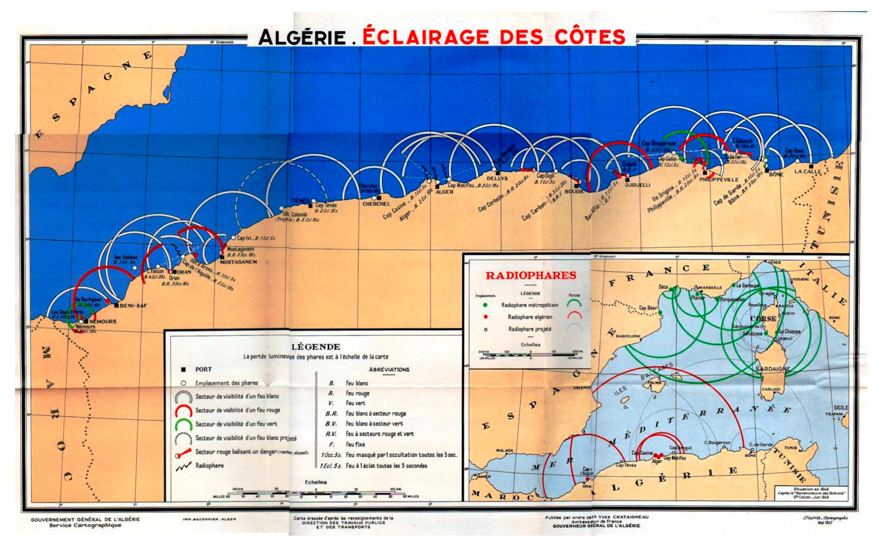
3. Lighthouses in Algeria

Like in many regions along the Mediterranean Sea, lighthouses in Algeria have existed for a long time, but their number increased during the French colonial era. The vast territory of the African inland was rich in agricultural and mineral products that could be conveniently exploited to sustain foreign trades, and this fostered the growth of the maritime navigation between Algeria and Europe, opening a direct major trading route [29].
Maritime signaling was much developed through the construction of several important lighthouses along the Algerian coastline, which stretches almost in a straight line from W.10° S to E.10° N for 1600 km (Figure 1) and sees presently the presence of a rich maritime organization and buildings. The lighthouses are generally spaced out in such a way that when sailing close to the land, even in thick fog at least one signal can be seen [30].
Algerian lighthouses bear witness to a long period of history and crystallize diversified architectural assets according to the period and place in which they were built. Consequently, a wide typological variability can be recognized, in relation to several geometrical criteria: form, height, and position of the towers.
Table 1 shows a morpho-typological survey of the lighthouses present along the Algerian coast in which the following elements have been classified: geometry in plan; maximum height; position of the tower in relation to the building. A total number of 24 buildings has been surveyed. For each category, the number of lighthouses showing that feature is reported in round brackets.

Seismic Vulnerability of Lighthouses from the 19th and 20th in Algeria

Algeria is one of the most active seismic regions of the Mediterranean Basin and in the past, it was hit by many destructive earthquakes. Northern Algeria has been mainly affected by moderate earthquakes and only occasionally by strong seismic events, among which the main ones are Algiers 1365 and 1673 (“Strong”, no estimate for macro-seismic intensity or magnitude); Oran 1790 (estimated magnitude 6.5–7.5); Blida 1825 (estimated magnitude 7.5); Djidjel 1856 (estimated magnitude 7.5) and Gouraya 1891 (estimated magnitude 7.5) [31]. The more recent events include those in 1910 at Aumale, 1954 at Orleans Ville, 1980 at El Asnam, 1985 at Constantine, 1985 at Tipaza, 1999 at Ain Temouchent, and 2003 at Bourmedes. The latter, which reached a 6.8 magnitude on the Richter scale, was the most destructive earthquake in the north of Algeria since that of El Asnam in 1980 [32]. During the event, the Centre for Applied Research in Earthquake Engineering recorded a maximum ground acceleration of 0.58 g E-W; 0.22 g N-S; 0.35 g vertical at their station in Keddara.
Regarding the actual classification of the seismic hazard, the northern part of Algeria is in a strong seismic area [33] and includes four different zones: zone I, zone II a, zone II b, and zone III. According to the Algerian seismic code [34], the maximum expected Peak Ground Acceleration (PGA) in each of the previous zones is, respectively: Z II a: PGA = 0.25 g; Z II b: PGA = 0.3 g and Z II: PGA = 0.4 g. There is an important ancient built environment in the coastal towns of the North, mainly consisting of masonry buildings (stone and/or brick) dating from the colonial period [35], among which several lighthouses that severely suffered, throughout the ages, the effects of seismic shocks. A notable example of the post-earthquake behavior of masonry towers in Algeria is given by the structural damage of Bengut Lighthouse after the May 2003 Boumerdès Earthquake.
Historical lighthouses are extremely vulnerable because of the following reasons:
  • Geometry of towers: as already mentioned, the tower generally has high compressive vertical stresses due to gravity loads. Under seismic loading, the slenderness can cause significant flexural loads and lateral drifts, easily leading to local damage or global collapses. The presence of adjoining structures can also influence the tower seismic vulnerability: the possible interaction reduces the slenderness of the tower but, at the same time, provides stress concentrations at the contact zone between tower and the confining structures [36].
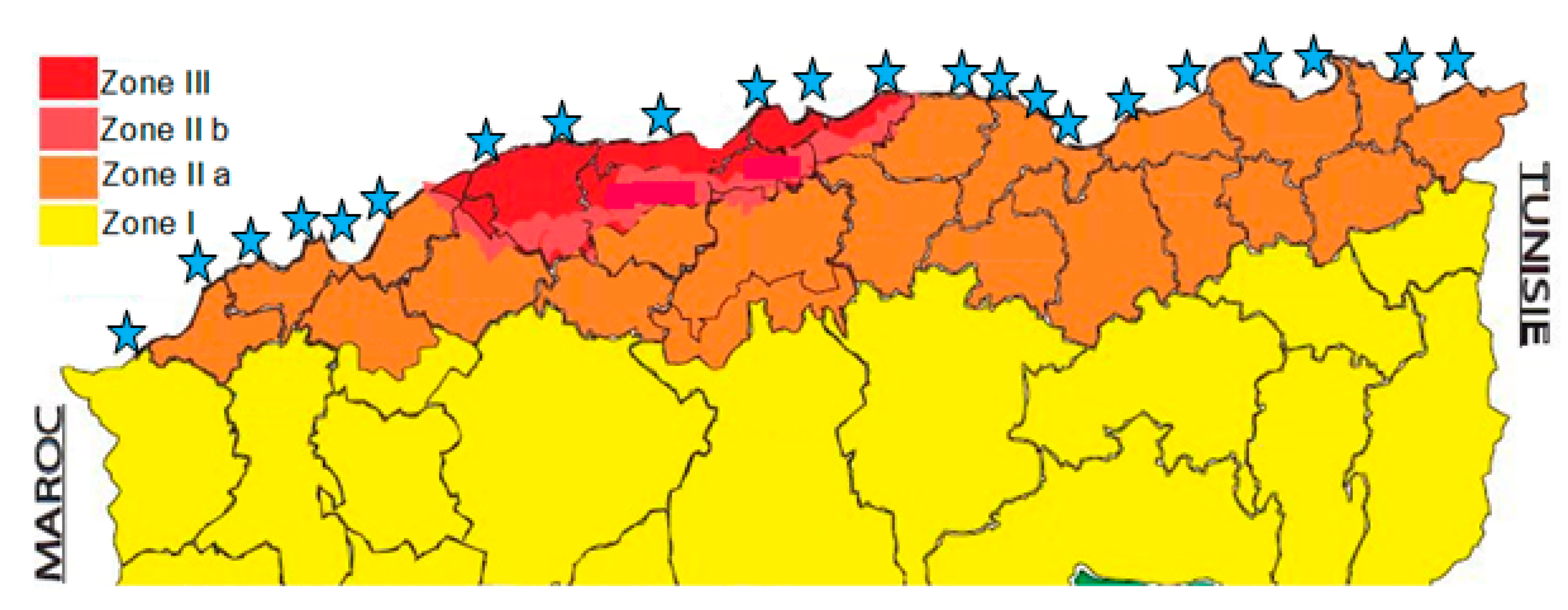
  • Geographical position: they are in zones of medium–strong seismicity (Figure 2).
  • Degradation due to age: the lighthouses dating from the French colonial era are sometimes more than 150 years old (the first one was built in 1861, the last one in 1954 [37]).

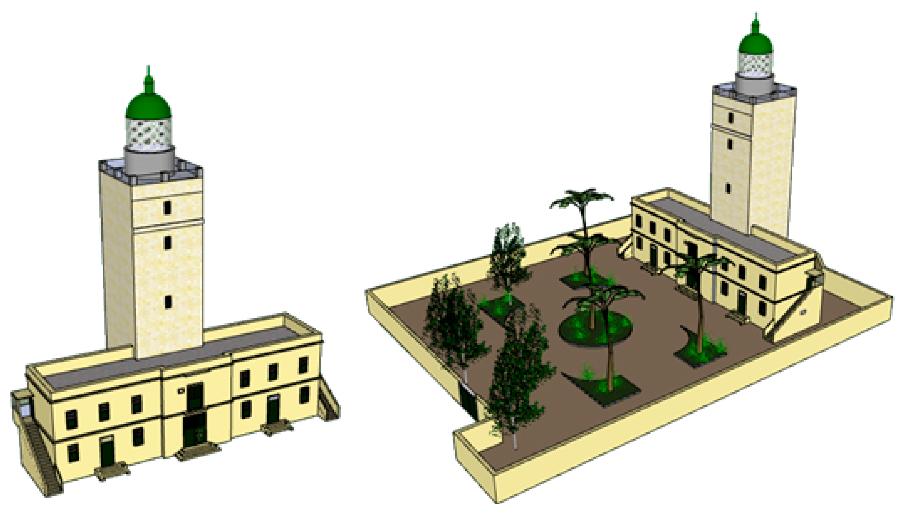
4. The Lighthouse at Cap Bengut

The Bengut Lighthouse, situated in the east of Algeria, in the town of Dellys, also known as “Bordj Fnar”, was built during the 19th century, more precisely in 1881, at a time when the town of Dellys flourished (Figure 3). In fact, it was of great importance for the maritime navigation [38]. After a century of service, it was put out of service due to a light non-structural damage caused by a terrorist bomb in 1994, first, and to the destruction (cracks, both deep and superficial, along the outside walls) and partial collapse of the ceilings caused by the Boumerdès Earthquake in 2003, later.
Today, the lighthouse is in a severe state of degradation due to lack of maintenance which lasted for more than 12 years. Despite the on-going restoration project that was launched in 2016, after the site was officially classified as “National Heritage” by the Algerian Ministry of Culture, at the present time only the buttresses of the vault ceilings have been installed.
The in-plan configuration of the lighthouse approximately consists of an elongated rectangle 29.6 m long and 6.35 m wide. It has two stories and is attached to a quadrangular tower, 33.1 m high, with base dimensions 7.40 m by 7.10 m. Additional information regarding the typology of the walls and their thickness, the mortar used, and floors is shown in Table 2.
In Figure 4, the main morphological features and irregularities of this building can be clearly observed:
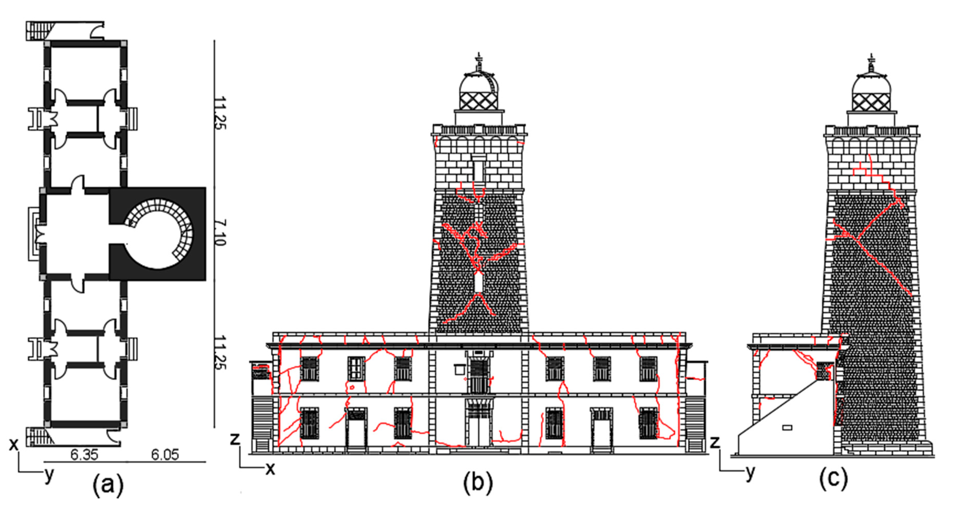
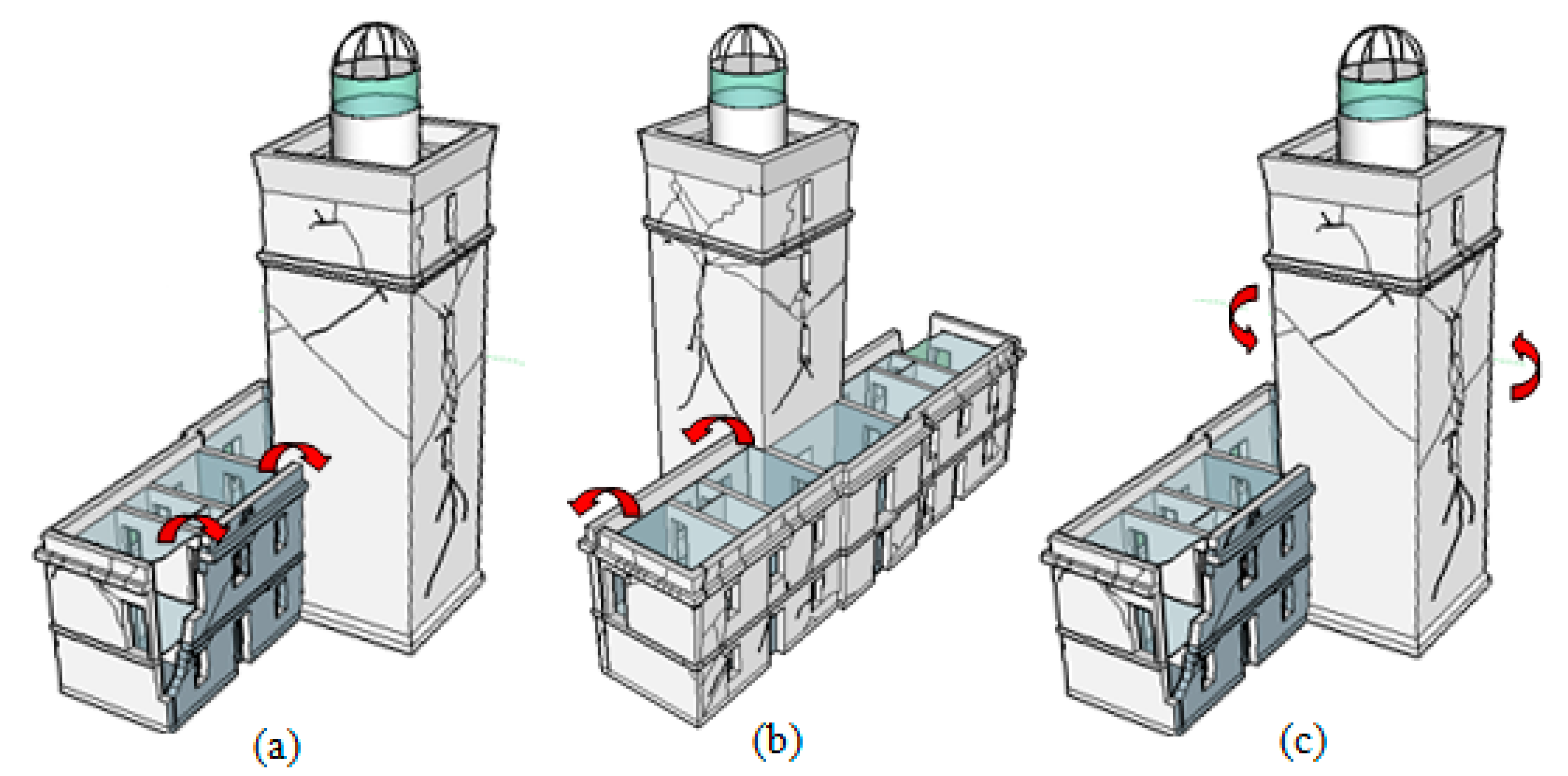
  • Geometric irregularity in plan (Figure 4a): the square tower is contiguous to a rectangular building.
  • Volumetric imbalance in elevation (Figure 4b): the total height of the tower equals three times the building height, with no seismic joints between them.
  • Bad connection between external walls in the corners, because of the poor effectiveness between chaining stone and walls.

5. Seismic Vulnerability Analysis of the Bengut Lighthouse

The case of the Bengut Lighthouse has been developed by tracing a methodological approach for the vulnerability assessment and performing numerical modeling and analysis based on the non-linear static approach, using the computer code TreMuri (educational version, S.T.A. Data, Turin, Italy) [39], a specific tool for the analysis of URM buildings, in which the seismic assessment is performed by the non-linear static method, according to the Italian seismic code [40], by determining the different capacity curves and limit states.

5.1. Identification of Collapse Mechanisms

First, the survey of the cracking and damage patterns presented in Section 4 has been analyzed and interpreted, to provide a systematic classification of the post-seismic situation and incipient collapse mechanisms. In Table 3, to facilitate the interpretation of the different collapse mechanisms of the lighthouse, the general categories are presented and explained through a description of the observed damage. In view of the restoration works and a possible conversion of the lighthouse into a marine museum, emergency wooden supports have been placed inside the building, just below the ceilings, to prevent their collapse, and steel stay-rods have been fixed inside the tower, from top to bottom.

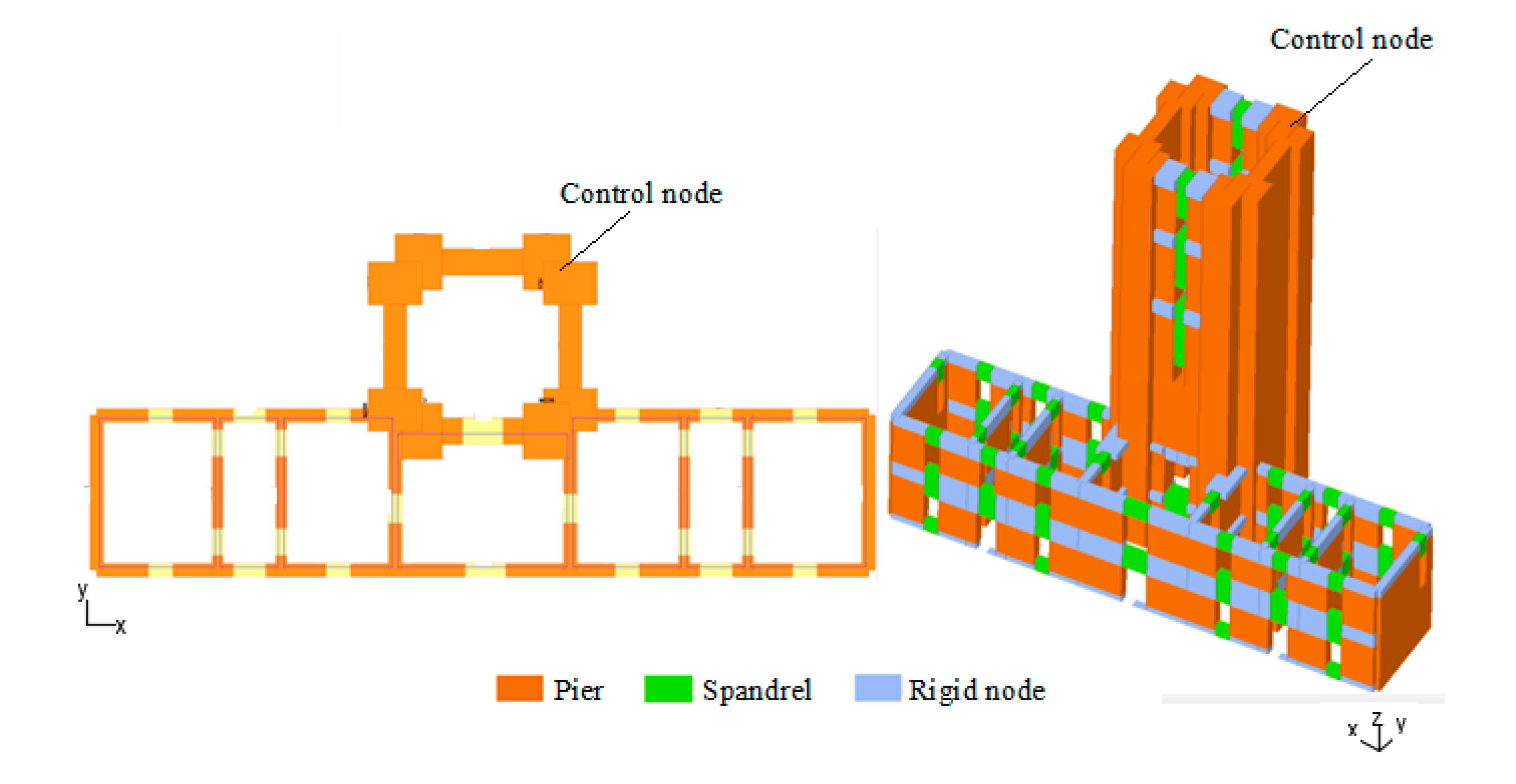
5.2. Numerical Analyses

Presently, no in situ investigation campaign has been conducted on the structures of the Bengut Lighthouse for identifying the mechanical properties of in situ materials. It should be remembered that the evaluation of seismic behavior of masonry structures is extremely complex and relies on the possibility of retrieving specific and accurate information about each case study: unfortunately, this is often very difficult because of the cost and invasiveness of investigations and tests aimed at the classification of the mechanical properties of materials and knowledge of the structural details. In the practice, it is almost impossible to perform extensive and detailed destructive tests, less destructive tests such as flat-jack tests are not reliable for many ancient masonry typologies, the simple relationships that extend the experimental properties of blocks and mortars to the whole masonry, which are provided for new masonry buildings, are not valid.
In the case of existing masonry buildings, the approach of the Italian code [40], which will be here followed, is to define a reference set of historical masonry types associated with specific range of variation (based on past experience and technical knowledge) and using both qualitative and experimental investigations for choosing the appropriate class and the value within the interval, also accounting for the factors of degradation of materials or, on the contrary, of reinforcement. Especially in the case of monumental buildings that have very peculiar features, a very effective approach would be the application of dynamic monitoring and structural identification procedures [41,42,43,44], to calibrate the parameters of the numerical models to be used in the verifications.
Anyway, it is important to observe that the objective of this study is not to perform a technical assessment for determining a safety level, but to define a general methodological framework for the seismic modeling of historical lighthouse, focusing the main aspects influencing seismic vulnerability (morphology, typology, construction quality, conceptual design) and the significant damage modes.
This is a fundamental basis on which in the operational phases, then, it will be possible to assess the final effect of the variability of mechanical parameters (which for historical masonry is particularly high) by means of wide sensitivity analyses.
In view of the numerical modeling and analysis, it was necessary to assume a range of reference for the mechanical parameters of materials. It is worth observing that in Algerian building codes there is no specific provision regarding the verification of existing buildings or the design of URM buildings [45]. Even after the 2003 Boumerdès Earthquake, the recent Algerian seismic code RPA2003 has not taken into consideration these aspects. In the lack of indications given by local standards, it was decided to refer to the Italian Technical Standards NT2018 [41] both for the assumption of the reference values of the mechanical parameters of materials (Table 4) and for the application of the non-linear static analysis.
Based on available documentation and visual inspections, the types and quality of the masonry composing the structure of the Bengut Lighthouse have been classified. The main building provides the presence of a rubble stone masonry type, whereas the tower presents two different types: regular block stone in the lower part, light cut stone in the upper part. After the visual inspections and the evaluation of the quality of the different masonry types (based on geometry, in-plane and out-of-plane texture, homogeneity, qualitative appraisal of degradation) [46], the masonry walls of the main building have been classified within the range “poor”-“bad”, whereas those of the tower, which exhibit much more homogeneity and with masonry quality, have been classified as “good”. Considering the type of masonry and the level of quality detected, the reference ranges and average values reported in Table 4 have been assumed for the numerical models. The choice of the ranges has been based on Table C8A.2.1C8.5.I contained in the Italian Circular of NT 2008 [47] and the typical values adopted in the scientific literature [16,17,19,20,21,36].
Regarding the seismic hazard, the response spectrum analysis has been performed referring to the RPA2003 [34]:
  • By following the classification table of RPA2003, the Bengut Lighthouse is classified as a building of great importance (group 1B).
  • It is in a high seismic hazard region (zone III), in which PGA is 0.3 g.
  • The soil classification is “hard rock”—S12.
  • A behavior factor R = 2 is assigned, by assuming the lowest class for existing URM buildings.
  • The quality factor “Q” of the structure defined by the Algerian code RPA 2003 depends on: redundancy in plan, regularity both in plan and elevation, quality control and execution of materials, and is Q = 1.35 for the building group 1B.
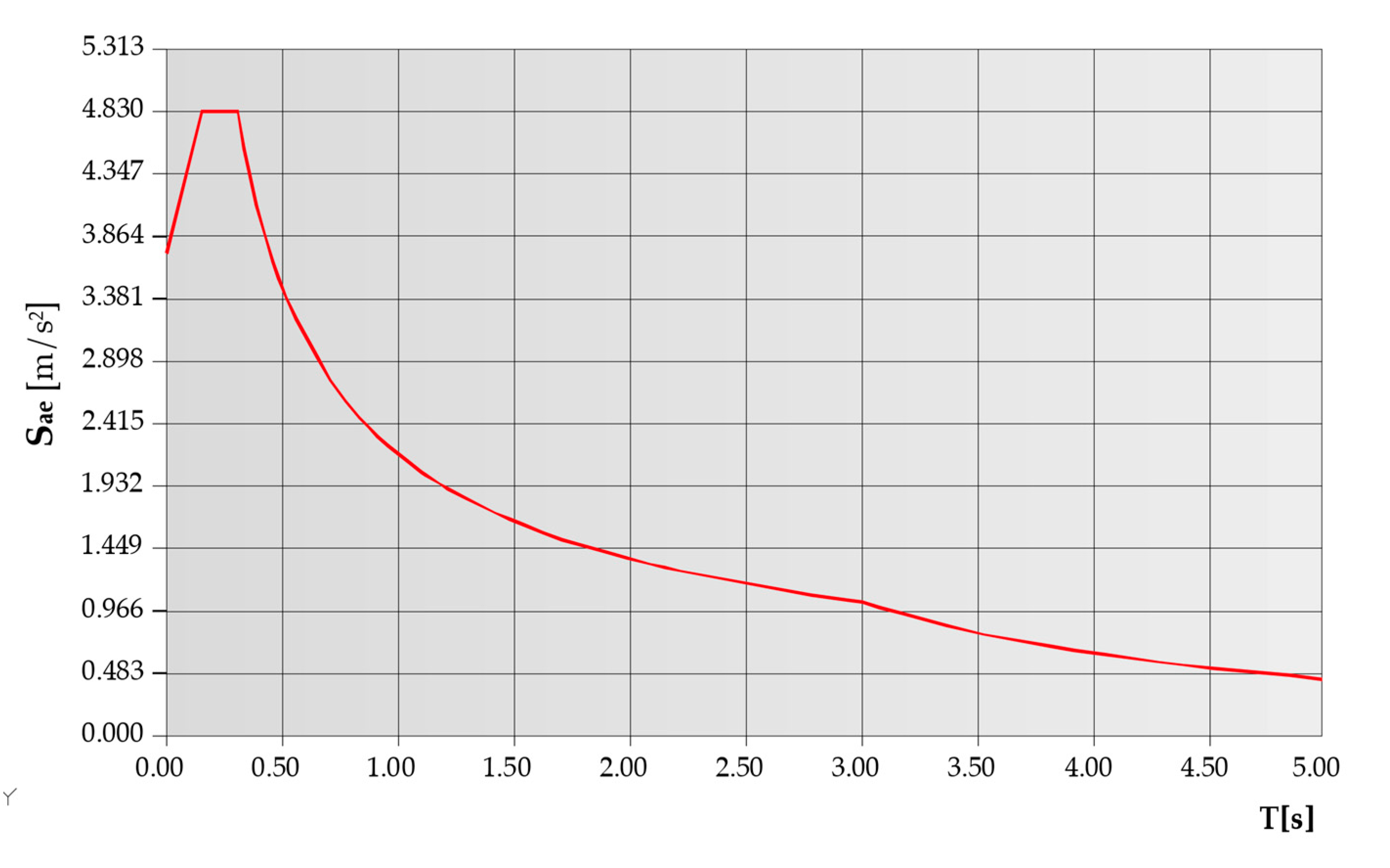
  • For the site of Bengut Lighthouse, the RPA03 response spectrum plotted in Figure 5 is adopted (the highest acceleration value is 0.483 g = 4.83 m/s).
The non-linear macro-element model (NLM) approach used TreMuri computer code [39,48,49] is based on the original formulation by Gambarotta and Lagomarsino [50]. The 3D model of Bengut Lighthouse implemented within TreMuri is presented in Figure 6. The numerical model is composed of three types of macro-elements: pier elements, spandrel elements and rigid nodes (213 elements, 76 rigid nodes, that are rigid elements connecting the resisting elements “pier” and “spandrels”). The mass of the lantern of the cupola is modeled as a dead load (16.21 kN/m2).

5.2.1. Preliminary Modal Analysis

The seismic vulnerability study of the Bengut Lighthouse has been carried out by performing, first, a preliminary modal analysis to assess the dynamic behavior of the structure and the potential damage modes. This analysis is useful to verify the consistency of the assumptions made in terms of material parameters and connections with respect to the general damage modes observed [51,52].
It is worthwhile remembering that the current Algerian legislation RPA 2003 [34] defines for the mass participation a limit value equal to 90% in both directions X and Y in cases of existing and new buildings. In the Italian [40] and European Codes [53], the application of linear dynamic analysis requires considering several modes that activates at least 85% of the participating mass.
Table 5 reports the first 12 vibration modes provided by the modal analysis: the participating masses in directions X and Y reaches the values 95.23% and 95.97%, respectively, before the 12th vibration mode. By looking at the results of the modal analysis, we can observe that the 1st and the 6th vibration modes are translational along X, with a period respectively of 1.22 s and 0.34 s, with a participating mass of 42.28% for the 1st mode and 34.09% the 6th one. The 2nd and the 5th modal forms are translational along Y and involve a participating mass respectively of 47.82% and 41.09%, with a period of 1.21 s and 0.37 s. The 11th modal form is torsional, with 55.05% participating mass along Z directions. It should be noted that the 3rd, 4th, 8th and 10th vibration modes are translational along X, with a very small mass participation, and represent local modes. All the other modal forms show a small and negligible participating mass. As a general comment we can say that the results of the modal analysis, with the presence of low participating mass in the first translational modes and of a relevant torsional mode, point out that a regular behavior cannot be clearly recognized, as typically encountered for masonry buildings which are not simple and regular in plan and in elevation. From a physical point of view, this means that under the earthquake the response of the building will be strongly affected by additional torsional effects, which can be particularly dangerous for the masonry walls, both in terms of additional in-plane bending and shear and in terms of out-of-plane stresses.

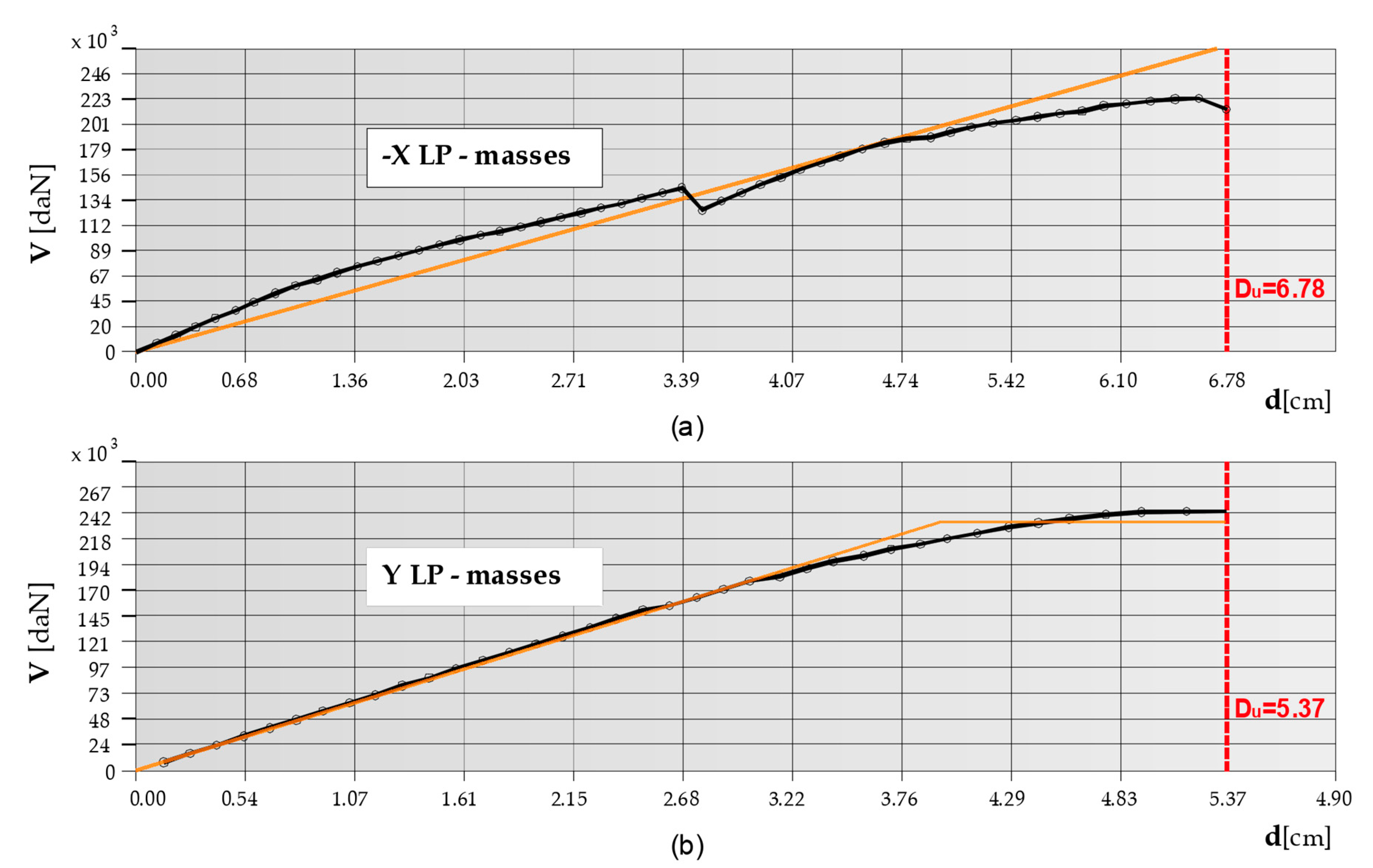
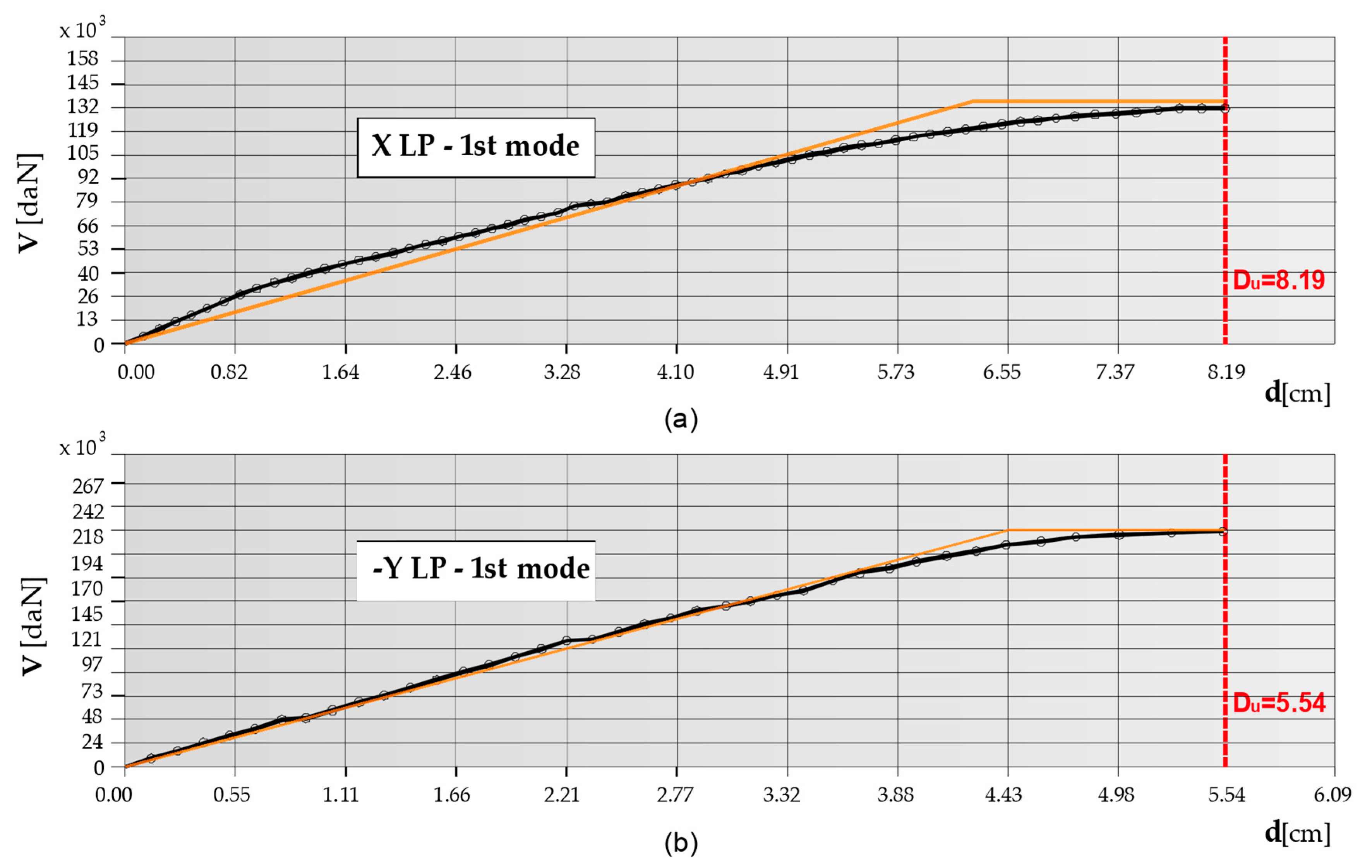
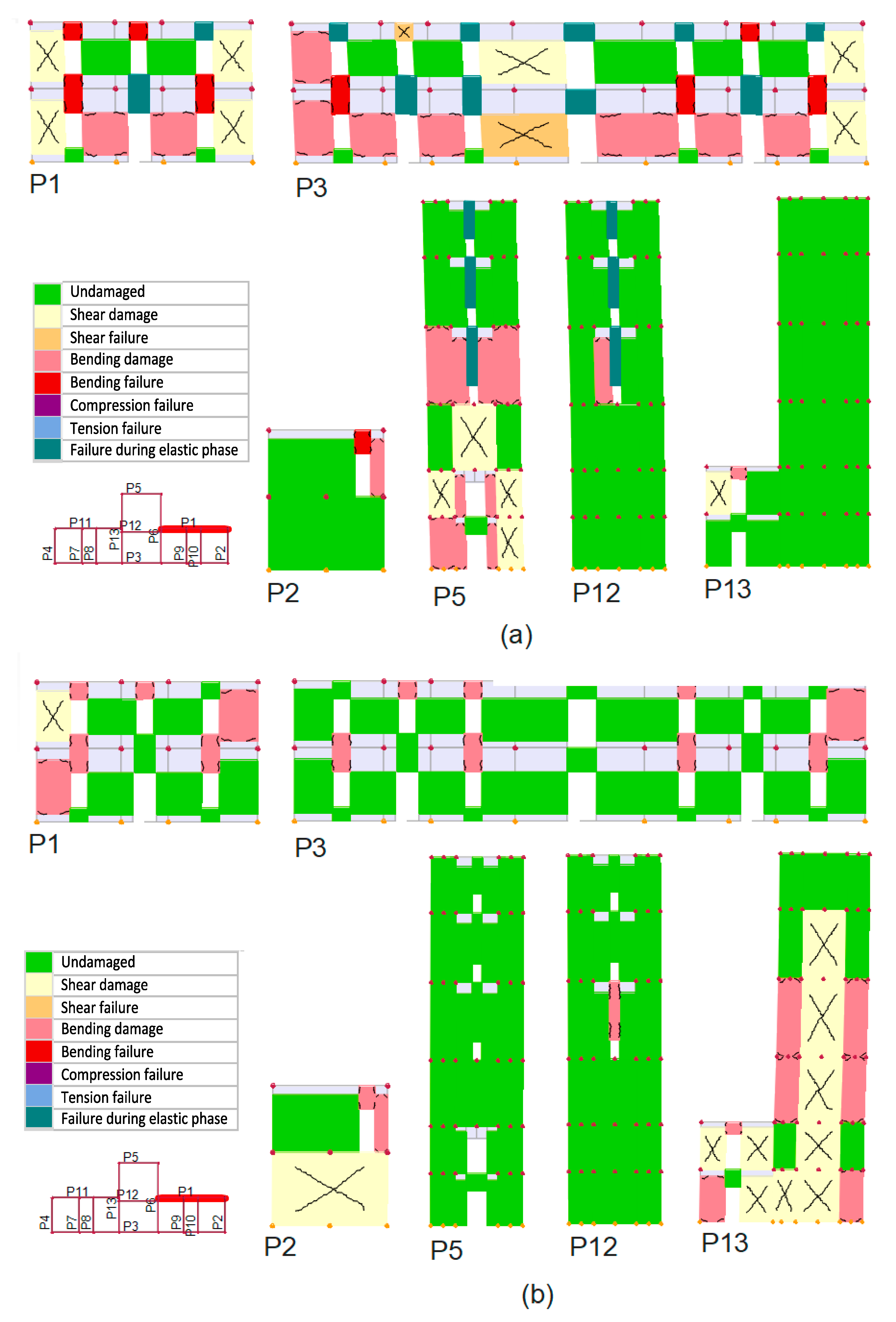
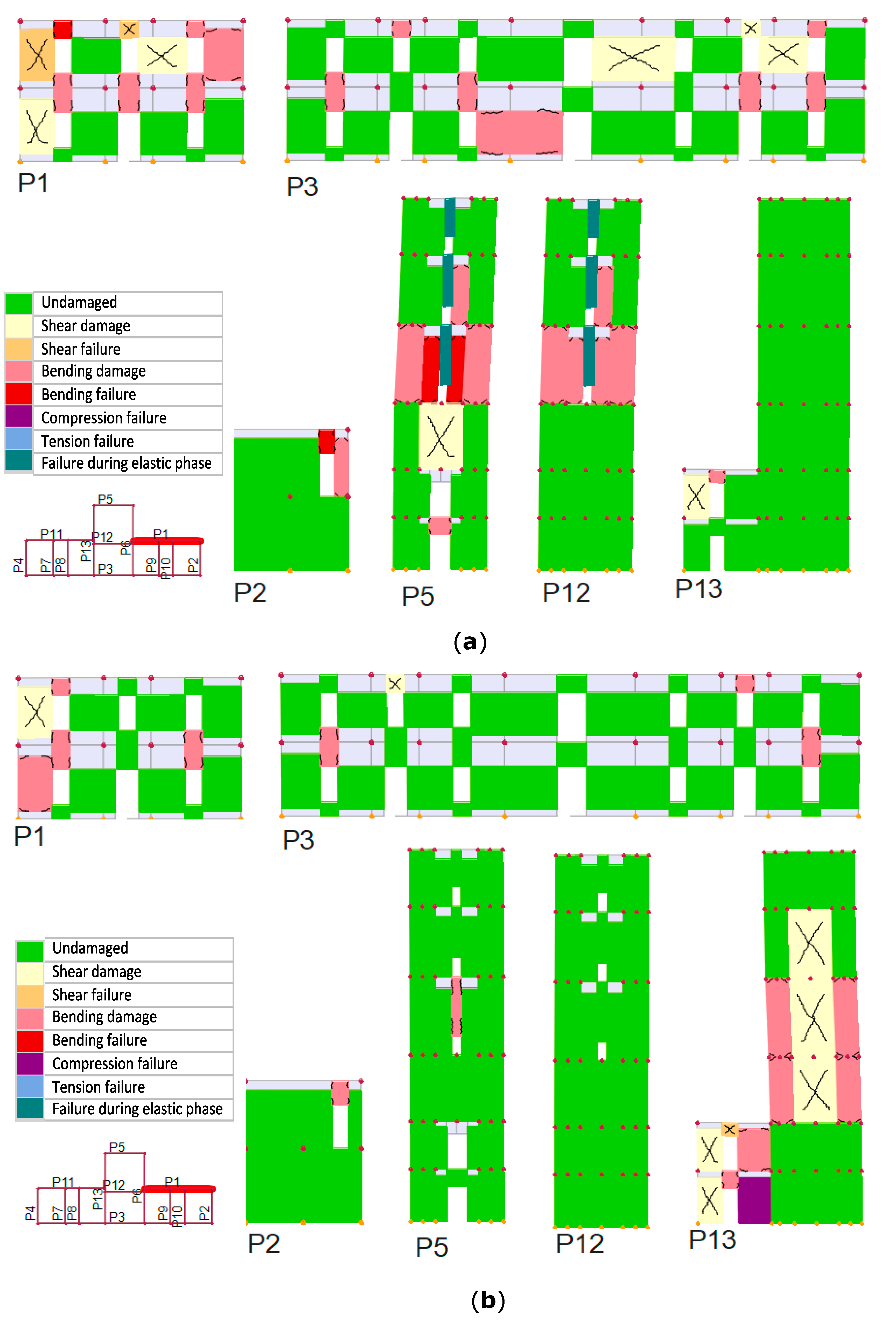
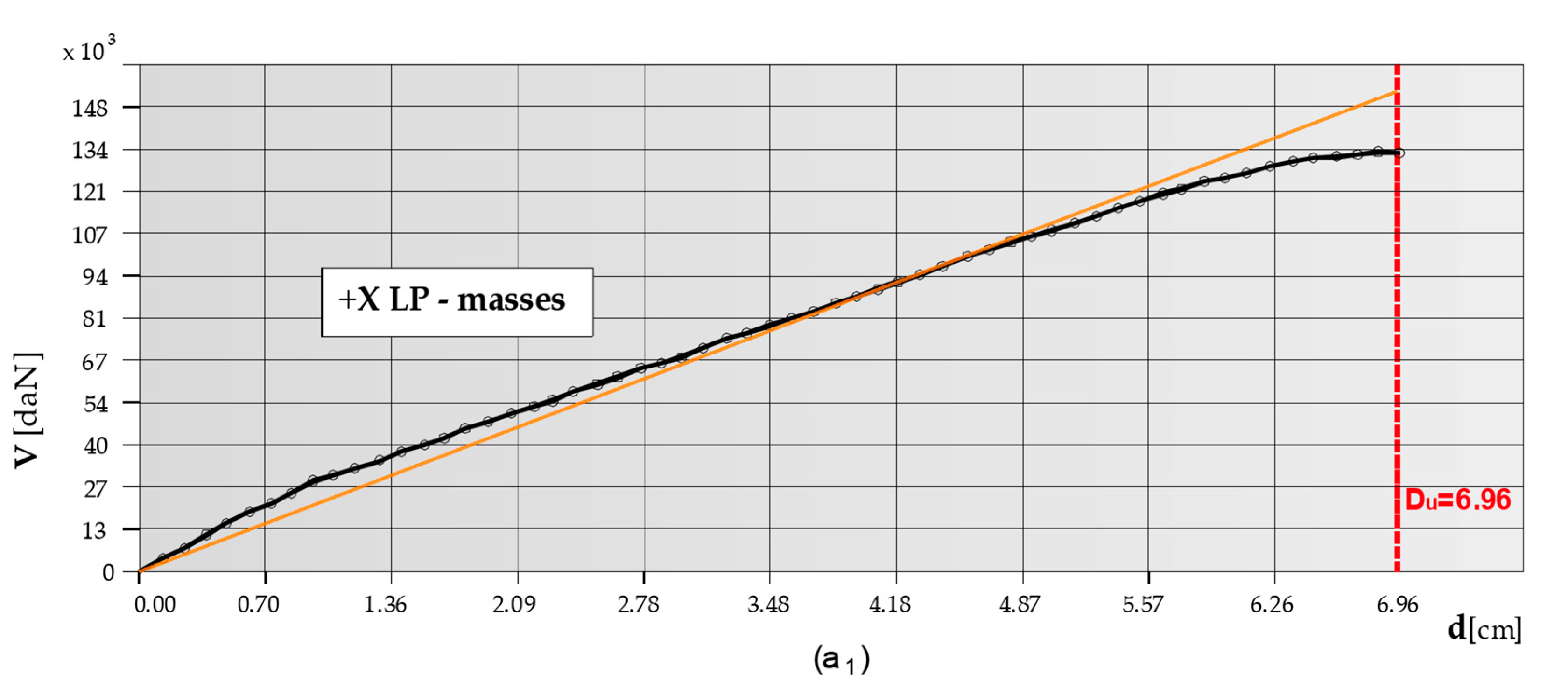
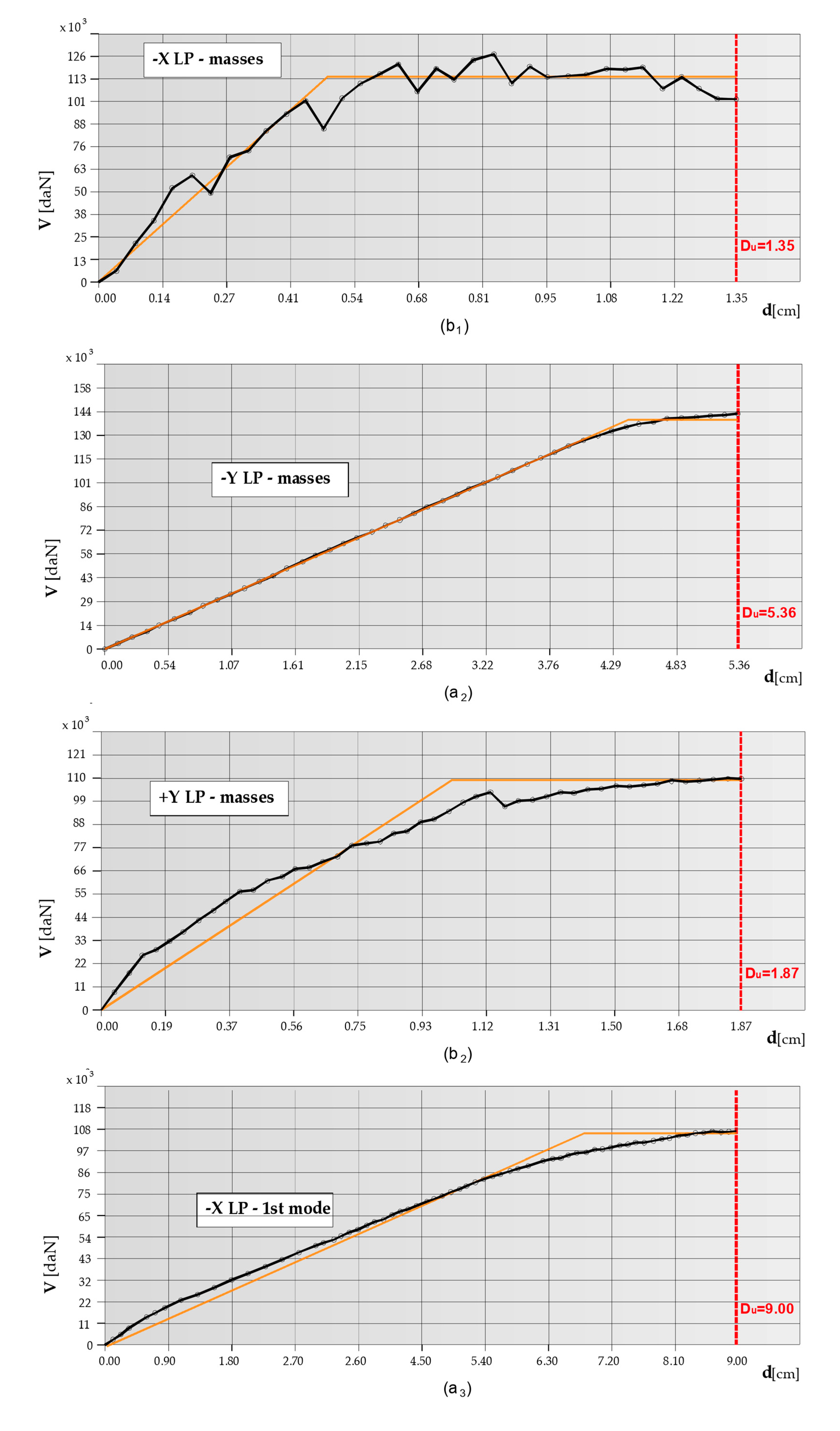
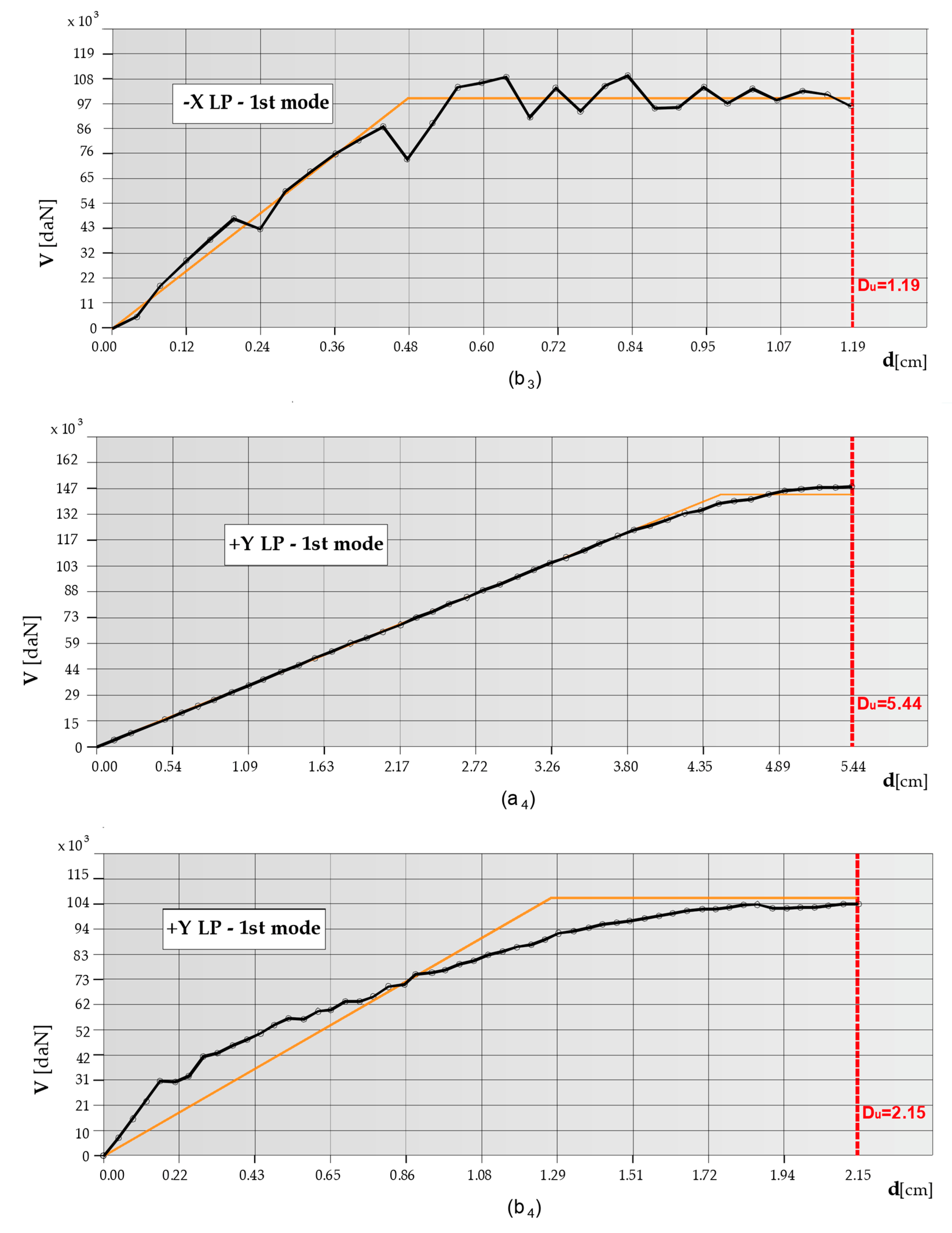
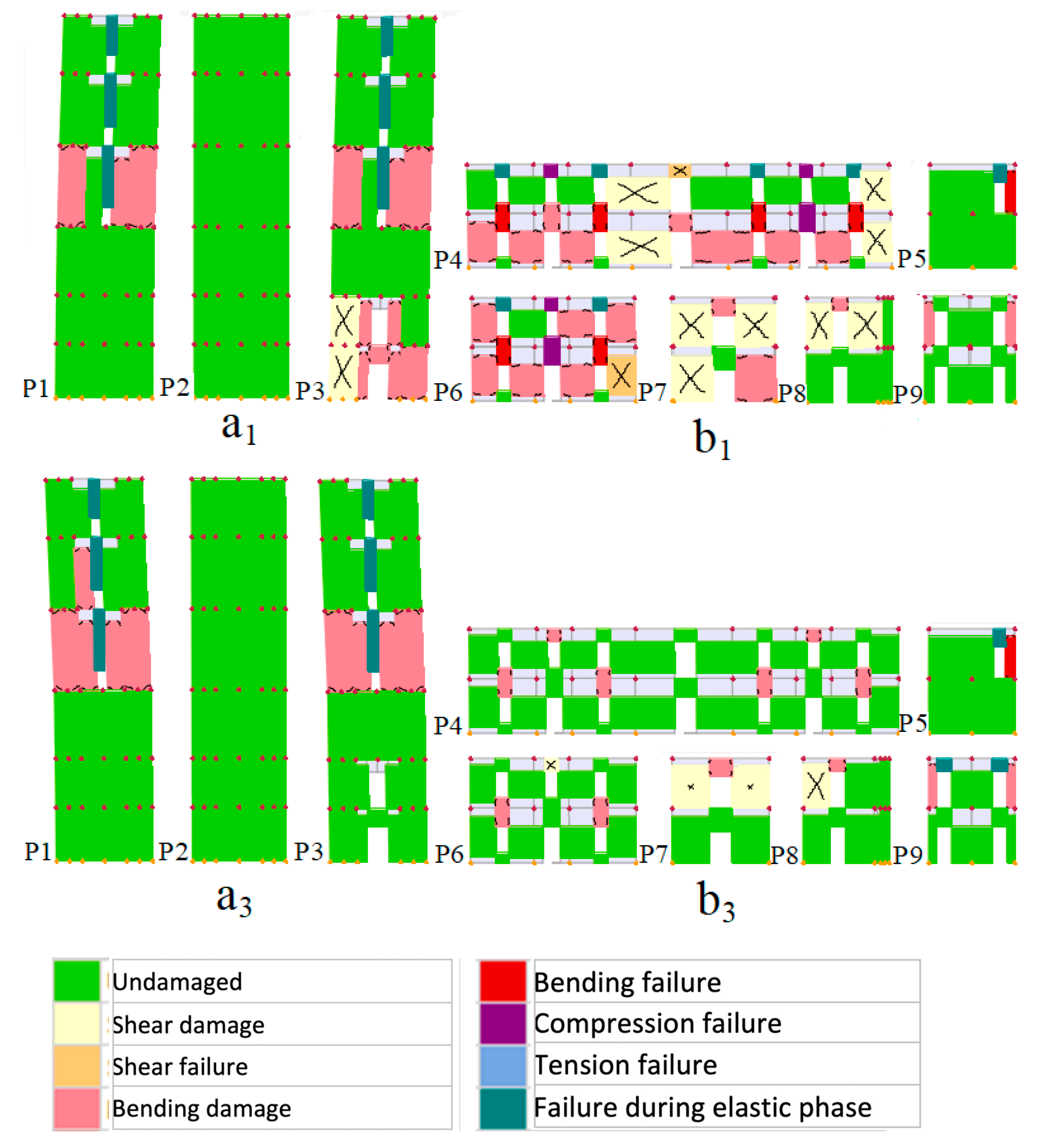
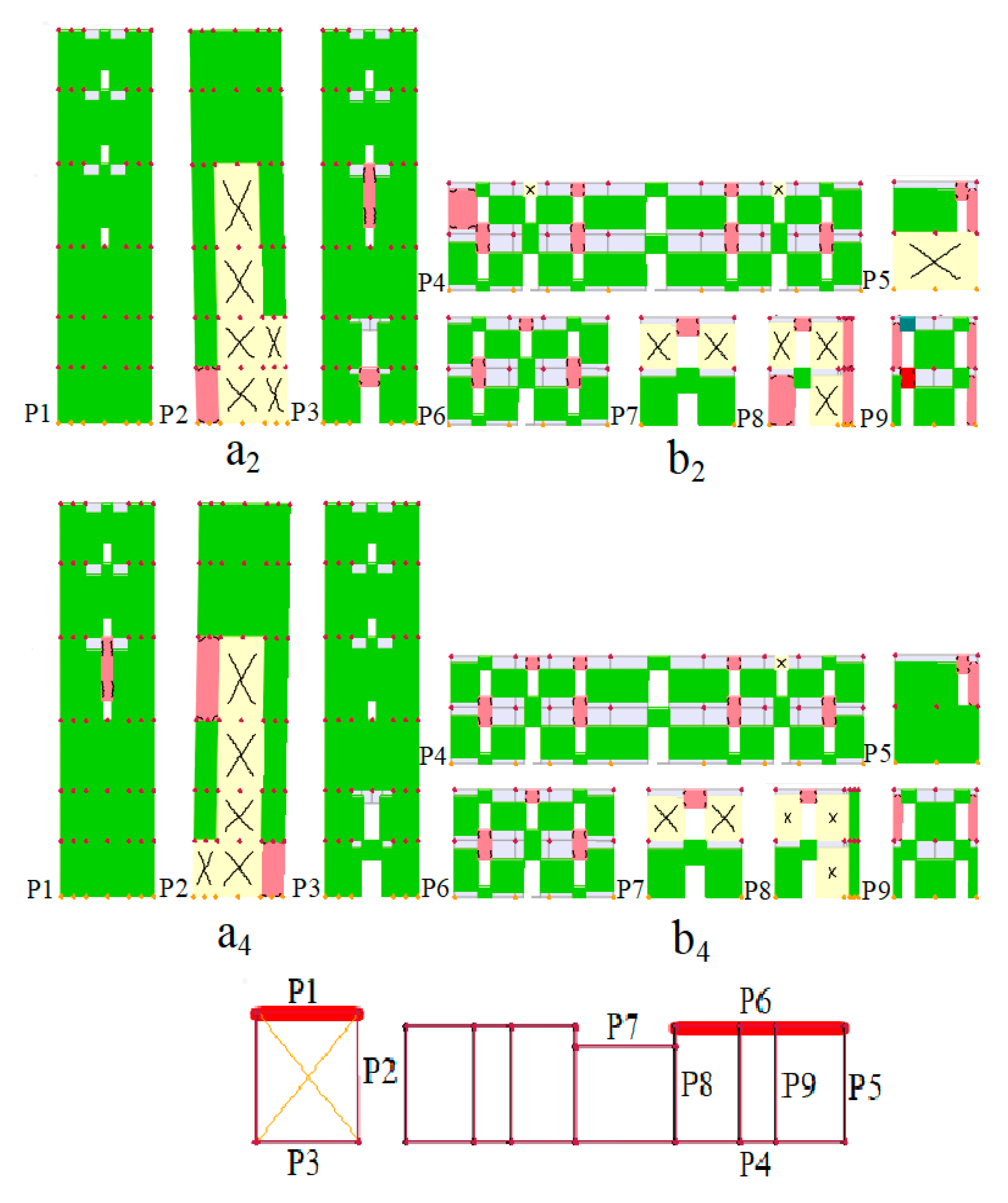
5.2.2. Pushover Analysis

The computational model of the structure has been loaded with a proper distribution of lateral loads that are gradually increased with the aim of “pushing” the structure into the non-linear field. In each direction, two profiles of lateral loads have been used: a pattern that represents lateral forces proportional to masses (uniform acceleration distribution)—LP-masses—and a modal pattern proportional to the first modal shape—LP-1st mode. The control node is placed at the corner of the top section of the tower (see Figure 6). The value of the horizontal displacements of this node is used to trace the capacity curves.
In Figure 7 and Figure 8, capacity curves in the −X and +Y directions, considering both the load profile proportional to the masses (LP-masses) and the load profile proportional to the first modal shape (LP-1st modal shape), are reported. In the plot, the ultimate displacement Du and the equivalent bilinear curve are also displayed.
The damage state in the structure walls is depicted in Figure 9a,b and Figure 10a,b. The capacity curve (a) obtained in −X direction with the load profile proportional to masses shows that the structure has mainly an elastic response, with an ultimate displacement Du = 6.78 cm.
In Figure 9a, it is possible to observe that the damage concentration is approximately symmetric on the East and a West side of the building and the main façade (P1, P11 and P3): a concentration of shear damage is located at the corner of the wall P3 (between P2 and P3, P4). The formation of a shear failure at the base and at the areas in contact with the tour (walls: P1, P11) can be observed. The bending damages are located at the corner of the walls P1 and P11. The piers of the openings at the walls P1, P11, and P3 develop a bending and compression failures. In the tower, the wall P12 fails for the formation of a shear hinge near the base and in the central part near the openings. A compressive failure appears in the walls P5 and P12.
The capacity curve in the +Y direction proportional to masses is shown in Figure 8b and shows that the structure has an elastic-plastic response with an ultimate displacement of 5.37 cm. The localization of the shear damage is mainly visible on the walls P6 and P13 along the height of the tower and on the building wall (areas in contact with the tower). The shear damage is concentrated at the base of the walls P2 and P13. In the case of load acting in +X direction proportional to the first mode, the capacity curve (c) shows an elastic-plastic trend. The ultimate displacement Du is found to be higher than other directions: Du = 8.19 cm. A shear failure is evident in the central area of the walls P5 and P12 of the tower. The formation of compressive failure in the piers of the tower can also be observed. The building’s walls P1 and P11 develop shear failure in the corner near the tower and bending damage in the other one.
The curve corresponding to the −Y direction proportional to the first mode (Figure 9b) is also elastic-plastic with an ultimate displacement Du = 5.54 cm. The damage map at the end of the analysis is basically the same as the one in +Y direction proportional to masses. It is possible to observe the formation of shear failure on the walls P1 and P11 at the corner. However, most of the shear failures are located, as expected, in the central part of tower and the base of the wall building (P6 and P13).
It is worth noting that the results provided by the pushover analyses in terms of in-plane damage pattern is in a good agreement with the actual distribution of cracks observed after post-earthquake surveys (Figure 4 and Table 3). Anyway, not all the post-earthquake damage observed in the surveys are captured by the numerical analyses, especially in the building, which exhibits significant damage modes related to local out-of-plane collapse mechanisms that cannot be captured by the global pushover analysis. The activation of local out-of-plane mechanisms is evident by looking at the actual cracks, as shown in Figure 11, which points out the presence of tree main local failure mechanisms: (a) Global overturning of the right back façade, (b) Partial overturning of the left back façade; (c) Overturning of the tower top.

6. Proposal of Retrofitting Solutions for the Bengut Lighthouse

6.1. A Literature Review of Seismic Repair and Retrofitting for Masonry Structures

The seismic repair and retrofitting of damaged masonry buildings require specific training and multi-disciplinary approach based on theoretical background and experimental basis.
As can be found in the literature review, seismic retrofitting techniques for masonry structures have been widely developed and practiced in recent decades. The first guidelines for the earthquake resistance of non-engineered constructions were published in 1986 by the International Association for Earthquake Engineering IAEE. Then, a series of documents on the assessment and strengthening was issued by the United States federal emergency management agency (FEMA). The reference European standards for the assessment for earthquake resistance and retrofitting of masonry structures are the Eurocode 6 [53] and Eurocode 8 [54]. Among national codes, the Italian NTC 2018 [41] presents the most comprehensive approach about retrofitting of masonry structures.
To prevent collapse under future seismic events, existing masonry buildings often require the implementation of adequate strengthening solutions aimed at enhancing their seismic response and, in general, the global structural performance. The present conditions of the Bengut Lighthouse are quite severe, and the vulnerability analysis carried out confirmed the visual evaluation, with a possible collapse of the tower. Therefore, the design of retrofitting interventions is an urgent step to be taken.
The proposal of retrofitting solutions for the Bengut Lighthouse is based first on the analysis of the morphological and constructive aspects discussed in Section 4, whereas specific guidelines are derived by the diagnosis of collapse mechanisms presented in Section 5.1 and by the results of non-linear static analysis discussed in Section 5.2. The reference technical law is the Algerian seismic code—recommendations RPA—and integrative orientations are provided by Eurocode 6 [53] about masonry structures. Regarding the approach to restoration, important references are the historic lighthouse preservation handbook [55] and several research studies reporting the techniques of retrofitting and structural strengthening schemes for masonry buildings [18,52,56,57,58,59,60,61,62]. These documents present some significant recent examples that illustrate interventions of retrofitting and repairing for masonry towers: the Monza cathedral belltower in Italy; the Church of Santa Maria Maggiore in Mirandola in Italy; the Church of Saint Christ in Outeiro in the North of Portugal and several American lighthouses: block island Southeast Lighthouse, cape Florida Lighthouse, and the Great Mosque of Dellys in Algeria.
The general framework is that of seismic retrofitting of existing buildings. Anyway, it should be remembered that any structural intervention on h buildings should respect as much as possible the original materials, construction techniques, and historical character of the structure. It is worth remembering, according to the fundamental principles of restoration, that the approach should provide at the same time effectiveness and minimum degree of invasiveness, maximum compatibility, and reversibility of the repair intervention. More exhaustive concepts and guidelines about the conservation and restoration of historical masonry buildings can be found in the different restoration charters (Venice, Athens, etc.) [63,64,65].
The choice of guidelines for the structural strengthening interventions on the Bengut Lighthouse will be supported by a numerical seismic re-evaluation to appraise the effectiveness of the adopted solutions on the global seismic behavior of the building. The proposed strengthening techniques have been modeled in a new numerical model and analyzed in terms of natural periods and vibration modes, ultimate displacements, and damage patterns.

6.2. Suggestions for Seismic Retrofitting Techniques

The general scheme of the repair and retrofitting proposed for the Bengut Lighthouse is described in Figure 12 and Figure 13. Two principal kind of structural techniques, acting both at a local and global level, are proposed to improve the structural stability and the seismic behavior of the building.
In the reference scientific literature, these structural solutions are considered to be particularly adequate for masonry towers and can be classified as follows:
Retrofitting techniques aimed at restoring the initial seismic behavior of the structure
To guarantee the continuity in the transmission of vertical loads under seismic excitation, the interventions suggested for repairing walls and floors are: rebuilding the collapsed parts of the north-east façade; reconstructing the collapsed part of the upper story; repairing the passing cracks; applying repointing technique to walls and substituting damaged stone (Figure 12 [18,56,57,59,60,66]).
More in detail:
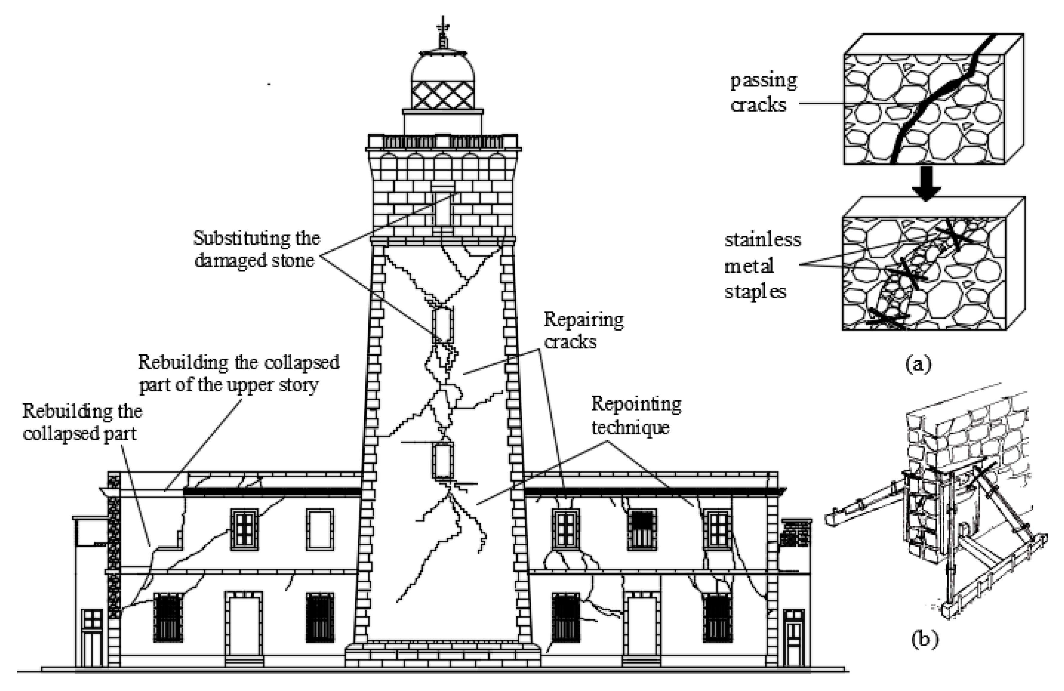
  • The collapsed part of the north-east façade shall be reconstructed by using materials with mechanical characteristics similar to the original ones. The objective of this intervention is only to restore the restore the original bearing capacity of the damaged parts.
  • The partial collapse of the roof has caused severe degradation to the whole structure because of water infiltration, humidity and corrosion of the steel IPE beams, and is a very urgent intervention to be taken. Therefore, the collapsed part of the floor will be rebuilt using bricks similar to the original ones and the steel IPE beams detached from the collapsed wall will be replaced with new ones and anchored to the supporting walls.
  • The masonry on both sides of passing cracks will be disassembled, restoring the gaps using stones of the same original material, stainless metal staples, and oblique mortar injections (Figure 12a). This technique is known “indenting” (“cuci e scuci” in Italy).
  • The mortar joints damaged by superficial cracks or infested by plant roots plants will be cleaned with compressed air and stripped to a depth of 3 cm, then moistened, and finally a liquid mortar will be introduced under pressure till the complete filling of vacuum (Figure 12b). The compatibility of the repointing mortars with the existent ones is a fundamental condition to assure the proper effectiveness of this intervention.
Retrofitting techniques to improve the structural stability and the seismic behavior of the building
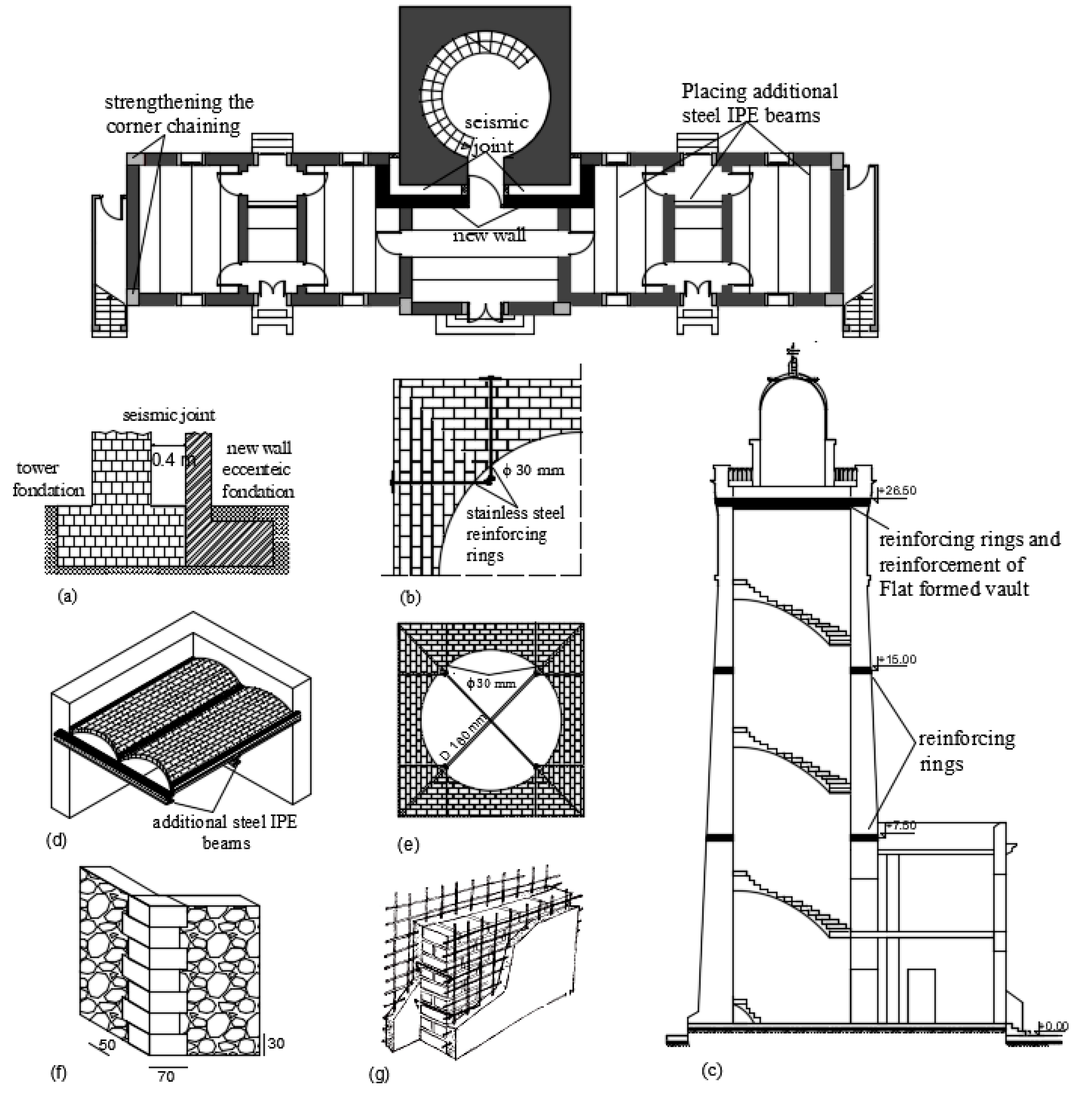
  • The most important provision to be taken consists of creating a seismic joint between the tower and the rest of the main building walls. According to RPA recommendations, if two neighboring structures have a steep difference in height, they should be separated by a seismic joint whose minimum displacement dmin satisfies the following condition:
dmin = 15 mm + (δ1 + δ2) mm ≥ 40 mm
δ1 and δ2 respectively represent the maximum displacements of the main building and of the tower at the roof.
This kind of interventions is surely advisable in the theory, but the operational execution could be difficult. Indeed, we propose that the original tower walls are preserved, whereas in the main building walls are rebuilt to properly support the floors and ensure the box-like behavior of the structure (Figure 13). The foundation of this new wall will be eccentric to preserve the original foundations (Figure 13a). The seismic joint between the original and new walls is calculated from Equation (1): dmin = 40 cm (the displacements δ1 = 2.48 cm, δ2 = 9.84 cm are deduced from the pushover analyses of the two separated structures).
  • A second important intervention to improve the structural behavior of the tower is the reinforcing of the four tower sides. This technique consists of inserting a series of horizontal stainless steel reinforcing rings all along the height of the tower Figure 13b, to confine the masonry, improve the connection between the orthogonal walls at the corners and assure the box-like behavior of the tower under seismic loads [18].
The position of the rings depends on the damages detected and the structural configuration. They are provided at three levels in the tower walls (Figure 13c): the first series will be inserted at a height of 7.50 m. The choice of reinforcing at this level is due to the proximity of the first floor of the building. The second series will be placed at a height of 15 m, since this zone, located between the openings, is already cracked, and its seismic vulnerability has been confirmed by the pushover analysis. The last series will be placed at the height of 26.50 m due to the presence of a flat vault at this level, to reinforce the connection between walls and floor.
  • The structural reinforcement of the floors is another important provision. The interventions will be applied both on the brick vault of the building and on the flat formed vault of the tower. Additional steel IPE beams will be screwed on the bottom part of the vaulted floor and will be anchored to the walls in a perpendicularly direction to the original IPE beams (Figure 13d) [57]; a diaphragm solution is proposed for the flat formed vault at the height of 26.50 m, consisting of a structure of steel elements and tie rods (Figure 13e) anchored in the exterior of the tower [18].
  • For guaranteeing the box-like behavior of the main building, the suggested intervention is the improvement of corner chaining, since the actual connection between the blocks in the external orthogonal walls is insufficient. The corner stone blocks will be dismantled and substituted with new ones of same nature and dimensions (50 cm × 70 cm × 30 cm), as shown in Figure 13f.
  • An additional intervention is proposed for guaranteeing the structural stability of interior walls and increasing their tensile strength, shear strength, and ductility. This technique has been largely applied in Italy. It consists first in jacketing the existing wall on both faces with wire meshes joined together by transversal steel ties, then in the application of a thick mortar layer on both faces. Overall, the thickness of the wall will be increased from 40 cm to 50 cm (Figure 13g) [56,57,60].

6.3. Seismic Re-Evaluation

For each strengthening solution proposed to the Bengut Lighthouse structure, it is important to check the structural effectiveness. This was supported by a modal analysis to estimate the new dynamic characteristics of the structure—natural periods and vibration modes of the two separated structures with the seismic joint—and a non-linear static analysis (pushover), for checking the new capacity curve and the damage state of the walls.
Table 6 shows the first three vibration modes of the original structure and those of the two separated structures (tower and main building). From the comparative analysis, the following conclusions can be derived:
  • The principal modes of the tower are similar to those of the original configuration, but with a strong increase in the participating masses. The 1st mode is translational along the direction X, the 2nd translational along the direction Y, and they have a comparable participating mass over 70%. The 3rd mode has very small mass participation and is a local mode. The mass participation is increased by approximately 30.57% and 25.43% in the 1st and 2nd mode, respectively.
  • Also, the main building, in the new configuration, has much higher values of the translational participating masses (over 90%). The 1st mode is translational along Y, the 2nd is a local mode with a very small mass participation and the 3rd is translational along X. The mass participation is increased by 50.01% in the X direction and 42.96% in Y direction.
As expected, the high irregularity of the structural compound, which was clearly highlighted by the low participating mass of the translational modes and by the presence of a relevant torsional rotation (Mz) is sanitized if the buildings are separated by a seismic joint.
To evaluate the efficiency of retrofitting solutions on the structural response of the tower and the main building, the capacity curves obtained by the pushover analysis for the two separate structures—tower and main building—are presented in Figure 14. The control nodes are chosen at the highest level (the average of all floor’s nodes is performed) and the load profiles are proportional to the masses and proportional to the first mode along X and Along Y (the worst situation is then selected and plotted). In Figure 15 and Figure 16 the deformed configurations and damage states of the main structures along X and Y directions are depicted.
The plots of the capacity curves and the deformed configurations presented in the figures show that the strengthening solutions are globally efficient. In the strengthened tower model, the displacement registered for the control node at the top of the tower attain a reduction of the approximately 10% on average along Y direction. The stress concentration occurred near the regions of the openings is reduced by comparing it with those in the original configuration. In the other direction, the capacity profiles show that the strengthening solutions have a slight increase of the displacement and the stress concentration in the vicinity of the openings is slightly reduced. This latter is due to the percentage of wall openings and the vulnerability of the tower to seismic action in this direction.
The retrofitting solutions significantly reduces the displacement at the top of the rectangular building by approximately 30% in the X direction, the stress distribution throughout the wall façades will be more uniform and the damaged area is significantly reduced along this direction. However, a slight increase of the displacement along the Y direction is observed, the concentration of stress is slightly reduced inducing local damages. This is attributable to the extensive length of the walls and the high percentage of wall openings in this direction. It is clear also that the low height of the building relative to that of the tower has a direct impact on the reduction of displacement percentage and stress concentration. The plots of the capacity curves and the deformed configurations presented in the figures show that the strengthening solutions are globally efficient. In the strengthened tower model, the displacement registered for the control node at the top of the tower attain a reduction of the approximately 10% on average along Y direction. The stress concentration occurred near the regions of the openings is reduced by comparing it with those in the original configuration. In the other direction, the capacity profiles show that the strengthening solutions have a slight increase of the displacement and the stress concentration in the vicinity of the openings is slightly reduced. This latter is due to the percentage of wall openings and the vulnerability of the tower to seismic action in this direction.

7. Concluding Remarks

Offshore lighthouses in Algeria are sometimes more than 150 years old, despite being in a region particularly prone to seismic hazard. They represent a very important element not only of the local historical architecture but also of a world historical patrimony that embodies in the maritime signals dedicated to navigation, the symbol of the history of explorations, and exchanges between peoples. In recent years, great attention has been paid to the theme of protection and conservation of lighthouses in several studies and research that combine architectural and historical aspects with the more technical issues of structural analysis.
Within this framework, the paper deals with the study of a case which is representative of the maritime heritage of Algeria: the Cap Bengut Lighthouse, in Dellys, with the objective of giving first an overview of the constructive, architectural, and geometrical features and then performing the seismic vulnerability. The seismic vulnerability evaluation of the lighthouse structure has been preceded by a visual structural diagnosis to identify the main collapse mechanisms. Then, a preliminary modal analysis and, finally, a non-linear static analysis (pushover) have been carried out in the +X, −X, +Y, and −Y directions, using profile loads proportional to the masses and the first modal shape. The results obtained in terms of capacity curves indicate that the structural behavior is mostly elastic, with a reduced level of ductility. The damage states have shown that the seismic damage concentration provided by pushover analysis are in a good agreement with the actual distribution of cracks observed after post-earthquake surveys, especially at the contact zone between the tower and the confining structure. The paper, moreover, discusses some proposals of seismic retrofitting techniques for the Bengut Lighthouse, in the respect of the restoration principle and of the original conception of the building. The structural effectiveness of the retrofitting solutions has been preliminarily investigated by the numerical analysis of the seismic behavior. Nevertheless, future developments will carry out wider investigations by means of dynamic analyses, to properly model the local out-of-plane collapse modes and account for the uncertainty both in the records and in models.
Despite the simplicity and generality of the model and of the numerical approach, a good prediction of the actual collapse mode exhibited by the structure has been obtained. The presented study, in perspective, can provide a basis for the seismic risk and vulnerability analysis of whole morpho-typical class of historical lighthouses at a large scale, exploiting a basis of knowledge which is sufficiently detailed from a geometric and constructive point of view but avoids—at least in a preliminary phase—the resort to expensive and time-consuming investigations, both experimental (extensive sampling and tests, monitoring, identification) and numerical (non-linear dynamic analyses). Very often, in fact, the lack of detailed data and the limited economic resources to fill the incomplete frame of knowledge needed to carry on the accurate assessment and design of interventions actually leads to a total absence of actions.
The road traced could be a basis to develop mechanical large-scale typological vulnerability models to be used not only for preliminary priority screening but also for the continuous monitoring of the built heritage, thanks for example to the implementation into GIS or DSS platforms that collect and update information and process it, providing alerts and indications about the criticalities.

Author Contributions

Methodology, G.U. and A.A.F.; validation, K.A., G.U. and A.A.F.; investigation, K.A.; data curation, K.A. and M.C.Z.; writing—original draft preparation, K.A. and G.U.; writing—review and editing, G.U. and K.A. All authors have read and agreed to the published version of the manuscript.

Funding

This research received no external funding.

Acknowledgments

The authors kindly acknowledge the members of ONSM (National Board of Lighthouse Authorities) for their help in the documentation research. For the fieldwork in Italy, the authors would like to thank the Erasmus + program; the thanks also go to Sergio Ruggieri and Andrea Nettis for their help in laboratory work. The research was supported by DGRSDT of Algeria (General Directorate of Scientific Research and Technological Development).

Conflicts of Interest

The authors declare no conflict of interest.

References

  1. Bartolomei, C. The Architecture of Italian Lighthouse; Alinea Edition: Firenze, Italy, 2005. [Google Scholar]
  2. Jonatan, C. Les phares antiques, entre défense et aide à la navigation. Exemples en Méditerranée Occidentale. Defensive Archit. Mediterr. XV XVIII Centuries 2015, 2, 65–70. [Google Scholar]
  3. CCLV. Les Phares de la Méditerranée; Chasse-Marée: Paris, France, 2009. [Google Scholar]
  4. ONSM. Etat de Signalisation Maritime: Phares et Balises; L’Office National de Signalisation Maritime: Alger, Algérie, 1979. [Google Scholar]
  5. AISM-IALA. IALA Lighthouse Conservation Manual, 1st ed.; AISM-IALA: Ile de France, France, 2006. [Google Scholar]
  6. MED-PHARES. Catalogo dei Fari e Semafori Delle Coste Tirreniche e Ioniche Italiane. Agenzia Conservatoria delle Coste, 2016. Available online: http://www.enpicbcmed.eu/communication/med-phares-project-looking-staff-0 (accessed on 20 November 2020).
  7. MED-PHARES. Catalogue des Phares et Sémaphores de Méditerranée Française. Conservatoire du Littoral, 2016. Available online: http://docplayer.fr/26356491-Catalogue-des-phares-et-semaphores-de-mediterranee-francaise.html (accessed on 20 November 2020).
  8. MED-PHARES. Catalogue des Phares et Sémaphores du Liban. Société pour la Protection de la Nature du Liban, 2016. Available online: http://www.sardegnaambiente.it/documenti/23_508_20171219171801.pdf (accessed on 20 November 2020).
  9. MED-PHARES. Catalogue des Phares de la Tunisie; Agence de Protection et d’Aménagement du Littoral: Tunis, Tunisia, 2016. [Google Scholar]
  10. Pelà, L. New trends and challenges in large-scale and urban assessment of seismic risk in historical centres. Int. J. Archit. Herit. 2018, 12, 1051–1054. [Google Scholar] [CrossRef] [Green Version]
  11. Polese, M.; Di Ludovico, M.; Gaetani d’Aragona, M.; Prota, A.; Manfredi, G. Regional vulnerability and risk assessment accounting for local building typologies. Int. J. Disaster Risk Reduct. 2020, 43. [Google Scholar] [CrossRef]
  12. Uva, G.; Sanjust, C.A.; Casolo, S.; Mezzina, M. ANTAEUS project for the regional vulnerability assessment of the current building stock in historical centers. Int. J. Archit. Herit. 2016, 10, 20–43. [Google Scholar] [CrossRef]
  13. Lourenço, P.B. Experimental and Numerical Issues in the Modeling of the Mechanical Behaviour of Masonry. In Structural Analysis of Historical Constructions II; Roca, P., González, J.L., Oñate, E., Lourenço Barcelona, P.B., Eds.; CIMNE: Barcelona, Spain, 1998; pp. 57–91. [Google Scholar]
  14. Uva, G.; Salerno, G. Towards a multiscale analysis of periodic masonry brickwork: A FEM algorithm with damage and friction. Int. J. Solids Struct. 2006, 43, 3739–3769. [Google Scholar] [CrossRef]
  15. Menon, A.; Magenes, G. Out-of-Plane Seismic Response of Unreinforced Masonry: Definition of Seismic Input; Research Report; IUSS Press/European School for Advanced Studies in Reduction of Seismic Risk: Pavia, Italy, 2008. [Google Scholar]
  16. Casolo, S.; Uva, G. Nonlinear analysis of out-of-plane masonry façades: Full dynamic versus pushover methods by rigid body and spring model. Earthq. Eng. Struct. Dyn. 2013, 42, 499–521. [Google Scholar] [CrossRef]
  17. Casolo, S. A numerical study on the cumulative out-of-plane damage to church masonry façades due to a sequence of strong ground motions. Earthq. Eng. Struct. Dyn. 2017, 46, 2717–2737. [Google Scholar] [CrossRef]
  18. Modena, C.; Valluzzi, M.R.; Folli, R.T.; Binda, L. Design choices and intervention techniques for repairing and strengthening of the Monza cathedral bell-tower. Constr. Build. Mater. 2002, 16, 385–395. [Google Scholar] [CrossRef]
  19. Casolo, S. Significant ground motion parameters for evaluation of the seismic performance of slender masonry towers. J. Earthq. Eng. 2001, 5, 187–204. [Google Scholar] [CrossRef]
  20. Casolo, S.; Diana, V.; Uva, G. Influence of soil deformability on the seismic response of a masonry tower. Bull. Earthq. Eng. 2017, 15, 1991–2014. [Google Scholar] [CrossRef]
  21. Casolo, S.; Milani, G.; Uva, G.; Alessandri, C. Comparative seismic vulnerability analysis on ten masonry towers in the coastal Po Valley in Italy. Eng. Struct. 2013, 49, 465–490. [Google Scholar] [CrossRef]
  22. Torelli, G.; D’Ayala, D.; Betti, M.; Bartoli, G. Analytical and Numerical Seismic Assessment of Heritage Masonry Towers. Bull. Earthq. Eng. 2020, 18, 969–1008. [Google Scholar] [CrossRef] [Green Version]
  23. Sangiorgio, V.; Pantoja, J.C.; Varum, H.; Uva, G.; Fatiguso, F. Structural degradation assessment of RC buildings: Calibration and comparison of semeiotic-based methodology for decision support system. J. Perform. Constr. Facil. 2019, 33. [Google Scholar] [CrossRef]
  24. Ruggieri, S.; Perrone, D.; Leone, M.; Uva, G.; Aiello, M.A. A prioritization RVS methodology for the seismic risk assessment of RC school buildings. Int. J. Disaster Risk Reduct. 2020, 51, 101807. [Google Scholar] [CrossRef]
  25. Sangiorgio, V.; Uva, G.; Adam, J.M. Integrated seismic vulnerability assessment of historical masonry churches including architectural and artistic assets based on macro-element approach. Int. J. Archit. Herit. 2020. [Google Scholar] [CrossRef]
  26. Ruggieri, S.; Tosto, C.; Rosati, G.; Uva, G.; Ferro, G.A. Seismic Vulnerability Analysis of Masonry Churches in Piemonte after 2003 Valle Scrivia Earthquake: Post-event Screening and Situation 17 Years Later. Int. J. Archit. Herit. 2020. [Google Scholar] [CrossRef]
  27. De Matteis, G.; Corlito, V.; Guadagnuolo, M.; Tafuro, A. Seismic vulnerability assessment and retrofitting strategies of italian masonry churches of the Alife-Aiazzo diocese in Caserta. Int. J. Archit. Herit. 2020, 14, 1180–1195. [Google Scholar] [CrossRef]
  28. Aiello, M.A.; Ciampoli, P.L.; Fiore, A.; Perrone, D.; Uva, G. Influence of infilled frames on seismic vulnerability assessment of recurrent building typologies. Ing. Sismica 2017, 34, 58–80. [Google Scholar]
  29. Lieussou, A. Etude sur les Ports d’Algérie; DGM Edition: Paris, France, 1857. [Google Scholar]
  30. Léon, R. Les Phares; The Navy Anchor: Paris, France, 1867. [Google Scholar]
  31. CRAAG. Les Séismes en Algérie de 1365 à 1992, CRAAG Report; Centre de Recherche en Astronomie Astrophysique et Géophysique: Bouzareah Alger, Algérie, 1994. [Google Scholar]
  32. Hamadach, M.; José, A.; Yelles, K.; Chauche, A. The Algiers, Algeria earthquake (M6.8) of 21 May 2003. Preliminary report. Seismol. Res. Lett. 2004, 75, 360–367. [Google Scholar] [CrossRef]
  33. Djeddi, M. Seism Tectonics and Seismology the North of Algeria, Department of Geophysics; University of Boumerdès: Boumerdès, Algeria, 2005. [Google Scholar]
  34. RPA99. Règles Parasismiques Algérienne; Centre National de Recherche Appliquée en Génie Parasismique, CGS: Alger, Algérie, 2003. [Google Scholar]
  35. Farsi, M.; Lazzali, F.; Ait-Méziane, Y. Stone Masonry Apartment Building. In World Housing Encyclopedia Report; EERI: Oakland, CA, USA, 2003. [Google Scholar]
  36. Bartoli, G.; Betti, M.; Vignoli, A.M. A numerical study on seismic risk assessment of historic masonry towers: A case study in San Gimignano. Bull. Earthq. Eng. 2016, 14, 1475–1518. [Google Scholar] [CrossRef]
  37. Zebar, Z.; Balhi, M. Les phares d’Algérie; Vigies de la côte; Kasbah édition: Alger, Algérie, 2015. [Google Scholar]
  38. Visbecq, M.A. Dellys: Petite Monographie Locale; L. Chaix Fils &C.: Alger, Algérie, 1925. [Google Scholar]
  39. S.T.A Data. 3Muri: Seismic Calculation of Masonry Structures According to the Italian Technical Codes for Constructions; S.T.A Data: Turin, Italy, 2016. [Google Scholar]
  40. Italian NTC 2018. New Technical Standards for Constructions; DM 17/01/2018; Ministero delle Infrastrutture e dei Trasporti, Istituto Poligrafico e Zecca dello Stato: Rome, Italy, 2018. (In Italian) [Google Scholar]
  41. Campione, G. Structural analysis, retrofitting design, and in situ control of permanently damaged long-span timber beams of a historical building in the south of Italy. Pract. Period. Struct. Des. Constr. 2020, 25. [Google Scholar] [CrossRef]
  42. Jaafari, C.; Mohammadi, J. Floor vibration control as a serviceability requirement in design standards and practices: Review. Pract. Period. Struct. Des. Constr. 2018, 23. [Google Scholar] [CrossRef]
  43. Bergamo, O.; Campione, G. Experimental investigation for degradation analysis of an RC italian viaduct and retrofitting design. Pract. Period. Struct. Des. Constr. 2020, 25. [Google Scholar] [CrossRef]
  44. Elias, S.; Matsagar, V. Seismic vulnerability of a non-linear building with distributed multiple tuned vibration absorbers. Struct. Infrastruct. Eng. 2019, 15, 1103–1118. [Google Scholar] [CrossRef]
  45. Abdessemed, F.A.; Misseri, A.; Rovero, G.L. Effects of the Boumerdès earthquake of May 21st, 2003 on the Great Mosque of Dellys (Algeria) and Solutions of the Restoration Project. In Proceedings of the Vienna Congress on Recent Advances in Earthquake Engineering and Structural Dynamics, Vienna, Austria, 28–30 August 2013. [Google Scholar]
  46. NIKER EU Project. Deliverable 3.1—Report Inventory of Earthquake-Induced Failure Mechanisms Related to Construction Types, Structural Elements, and Materials, Annex 1: Damage Abacus. Politecnico di Milano: 2010. Available online: http://www.niker.eu/assets/Files/Download (accessed on 20 November 2020).
  47. NIKER EU Project. Instructions for the Application of the Technical Building Code (NTC, 2008); Ministero delle Infrastrutture e dei Trasporti Istituto Poligrafico e Zecca dello Stato: Rome, Italy, 2009. (In Italian) [Google Scholar]
  48. Penna, A. A Macro-Element Procedure for the non-Linear Dynamic Analysis of Masonry Buildings. Ph.D Thesis, Politecnico di Milano, Milan, Italy, 2002. [Google Scholar]
  49. Lagomarsino, S.; Penna, A.; Galasco, A.; Cattari, S. TreMuri program: SeismicAnalyses of 3D Masonry Buildings, Release 2.0; University of Genoa: Genova, Italy, 2012. [Google Scholar]
  50. Gambarotta, L.; Lagomarsino, S. On Dynamic Response of Masonry Panels. In National Conference “Masonry Mechanics between Theory and Practice”; Ed. Pitagora: Messina, Italy, 1996. [Google Scholar]
  51. Darwish, M.; Rashwan, M. Structural dynamic characteristics of ancient Egyptian obelisks and their responses to earthquake loads. Pract. Period. Struct. Des. Constr. 2018, 23. [Google Scholar] [CrossRef]
  52. Avci, O.; Al-Smadi, Y.M. Unreinforced masonry façade assessment of a historic building for excessive displacements due to a nearby subway construction. Pract. Period. Struct. Des. Constr. 2019, 24. [Google Scholar] [CrossRef]
  53. EN 1996-1:2005. Eurocode 6: Design of Masonry Structure; CEN, European Committee of Standardisation: Brussels, Belgium, 2005. [Google Scholar]
  54. EN 1998. Eurocode 8: Design of Structures for Earthquake Resistance; CEN, European Committee of Standardisation: Brussels, Belgium, 1999. [Google Scholar]
  55. NPS; USCG; DDLRMP; USLS. Historic Lighthouse Preservation, 1997. Available online: https://www.nps.gov/maritime/nhlpa/handbook.htm (accessed on 20 November 2020).
  56. Penazzi, D.; Valluzzi, M.R.; Saisi, A.; Binda, L.; Modena, C. Repair and Strengthening of Historic Masonry Buildings in Seismic Areas. In Proc. Int. Millennium Congress ‘More than Two Thousand Years in the History of Architecture Safeguarding the Structure of Our Architectural Heritage; UNESCO: Bethlehem, Palestine, 2001. [Google Scholar]
  57. Chuang, S.W.; Zhuge, Y. Seismic Retrofitting of Unreinforced Masonry Buildings-A Literature Review. Aust. J. Struct. Eng. 2005, 6, 25–36. [Google Scholar] [CrossRef]
  58. Brandois, P.; Babics, F. Manuel de Sensibilisation à la Restauration de la Maçonnerie; Ministère de la Culture et de la Communication: Paris, France, 2006. [Google Scholar]
  59. Navarro, J.L.G. Diagnostic et Traitement des Pathologies Structurelles du Bâtiment; Institut National du Patrimoine tunisie: Kairouan, Tunisia, 2006. [Google Scholar]
  60. Díaz, G.C. La réhabilitation des éléments structuraux de l’architecture traditionnelle méditerranéenne. Méthode RehabiMed: Les Techniques de Réhabilitation; Renforcer les Structures 2007, 8, 297–308. [Google Scholar]
  61. Vicente, R.; Rodrigues, H.; Varum, H.; Silva, J.A.R. Evaluation of strengthening techniques of traditional masonry buildings: Case Study of a four-building aggregate. J. Perform. Constr. Facil. 2011, 25, 202–216. Available online: www.nps.gov (accessed on 20 November 2020). [CrossRef] [Green Version]
  62. D’Ayala, D. Seismic Retrofit of Earthquake Damaged Masonry Housing; K4D Helpdesk Report: Brighton, UK, 2016. [Google Scholar]
  63. Croci, G. The conservation and structural restoration of architectural heritage. In Computational Mechanics Publications; WIT Press: Southampton, UK, 1998. [Google Scholar]
  64. ICOMOS. Recommendations for the Analysis, Conservation and Structural Restoration of Architectural Heritage. In Proceedings of the ICOMOS 14th General Assembly, Victoria Falls, Zimbabwe, 27–31 October 2003. [Google Scholar]
  65. D’Ayala, D. Conservation Principles and Performance-Based Strengthening of Heritage Buildings in Post-Event Reconstruction; Springer International Publishing: Cham, Switzerland, 2014. [Google Scholar]
  66. Laefer, D.; Baronio, G.; Anzani, A.; Binda, L. Measurement of Grout Injection Efficacy for Stone Masonry walls. In Proceedings of the Seventh North American Masonry Conference, The Masonry Society, Boulder, Colorado, 2–5 June 1996; pp. 484–496. [Google Scholar]
Figure 1. Lighting map of the Algerian coast showing the network of lighthouses deployed during the French colonial era (1947).
Buildings 10 00247 g001
Figure 2. Geographical location of the lighthouses in the seismic map of Algeria, CGS.
Buildings 10 00247 g002
Figure 3. 3D drawings of the Bengut Lighthouse.
Buildings 10 00247 g003
Figure 4. Drawings of the Bengut Lighthouse: (a) plan view; (b) main façade with indication of the damage distribution; (c) lateral views with indication of the damage distribution.
Buildings 10 00247 g004
Figure 5. RPA03 Response Spectrum for the Site of Bengut Lighthouse.
Buildings 10 00247 g005
Figure 6. The non-linear macro-element model (NLM) of the Bengut Lighthouse implemented in TreMuri computer code.
Buildings 10 00247 g006
Figure 7. Plots of the capacity curves, corresponding equivalent bilinear curves, and maximum available displacement Du. (a) Pushover in −X direction, LP-masses. (b) +Y direction, LP-masses.
Buildings 10 00247 g007
Figure 8. Plots of the capacity curves with the corresponding equivalent bilinear curves and maximum available displacement Du. (a) Pushover in −X direction, LP-masses. (b) +Y direction, LP-masses.
Buildings 10 00247 g008
Figure 9. Damage state of the main walls in X and Y directions: (a) Damage state in the −X direction, LP-masses. (b) +Y direction, LP-masses.
Buildings 10 00247 g009
Figure 10. Damage state of the main walls in X and Y directions: (a) Damage state in the −X direction, LP-1st mode. (b) +Y direction, LP-1st mode.
Buildings 10 00247 g010
Figure 11. 3d sketches of the failure mechanisms: (a) Global overturning of the right back façade, (b) Partial overturning of the left back façade; (c) Overturning of the tower top.
Buildings 10 00247 g011
Figure 12. North façade of the Bengut Lighthouse with the location of the different types of the reinforcing interventions: (a) Repair of passing cracks; (b) Repointing technique.
Buildings 10 00247 g012
Figure 13. Plan view of the Bengut Lighthouse with the different types of the reinforcing interventions and details of the: (a) Seismic joint; (b) Strengthening the tower corners; (c) Location of the reinforcing rings; (d) Reinforcing the brick vault; (e) Reinforcing the flat formed vault; (f) Strengthening the building corner; (g) Increasing the interior walls thickness.
Buildings 10 00247 g013
Figure 14. Plots of the capacity curves, with the corresponding equivalent bilinear curves and maximum available displacement Du. (a) Pushover of the tower. (b) Pushover of the rectangular building: (a1,b1) In the X direction and LP-masses. (a2,b2) In the Y direction and LP-masses. (a3,b3) In the X direction and LP-1st mode (a4,b4) In the Y direction and LP-1st mode.
Buildings 10 00247 g014aBuildings 10 00247 g014bBuildings 10 00247 g014c
Figure 15. Damage state of the main walls in X and Y directions: (a) Damage state of the tower walls. (b) Damage state of the rectangular building. (a1,b1) In the X direction proportional to masses. (a3,b3) In the X direction proportional to the first mode.
Buildings 10 00247 g015
Figure 16. Damage state of the main walls in X and Y directions: (a) Damage state of the tower walls. (b) Damage state of the rectangular building. (a2,b2) In the Y direction proportional to masses. (a4,b4) In the Y direction proportional to the first mode.
Buildings 10 00247 g016
Table 1. Morpho-typological classification of Algerian lighthouses according to form, height, and position of the tower.
In-plan shapeQuadrangular (11)Circular (08)Octagonal (05)
Buildings 10 00247 i001 Buildings 10 00247 i002 Buildings 10 00247 i003
Height10–20 m (16)20–30 m (07)30–40 m (01)
Buildings 10 00247 i004 Buildings 10 00247 i005 Buildings 10 00247 i006
Position of the towerAt the center of building (09)Attached to the building (10)Independent (05)
Buildings 10 00247 i007 Buildings 10 00247 i008 Buildings 10 00247 i009
Table 2. Constructive techniques of walls and floors.
Structural ElementGeometrical SchemeDescription
Walls of the main building Buildings 10 00247 i010Walls made of rubble stone.
Thickness of exterior walls: 50 cm, chaining at angles.
Thickness of interior walls: 40 cm.
Walls of the tower Buildings 10 00247 i011Walls build of cut stone masonry.
Floors Buildings 10 00247 i012Vaulted ceilings.
Flat formed arches made from cut stone.
Table 3. Classification of collapse mechanisms.
Damage AbacusIllustrationDescription
Global overturning of the façade Buildings 10 00247 i013Separation of the north-west façade from the lateral walls in proximity of the corner, because of the insufficient connection between orthogonal walls and between walls and floors.
Partial overturning with diagonal rotation axis Buildings 10 00247 i014Vertical overturning of the north-east façade, with corner expulsion. This out-of-plane mechanism, with provides local failures of the upper part of the walls and collapse, is due to the stress concentrations that occur at the intersection of transverse walls and to the presence of large openings.
Shear mechanism in the façade plane Buildings 10 00247 i015Cracks in the façades:
  • X-shaped shear cracks
  • Central vertical crack or arched cracks near the corner
  • Diagonal cracks (single and crossed) in masonry panels.
Overturning of the tower top Buildings 10 00247 i016Vertical, horizontal, and diagonal thin cracks in the four sides of the tower, due to long-term compressive actions and seismic bending actions.
Shear cracks of the internal walls Buildings 10 00247 i017Diagonal and vertical cracks in the inner partition walls.
Floor damage Buildings 10 00247 i018Cracks in the vaults. Partial expulsion of the upper story and detachment of steel IPN beams from side walls.
Table 4. Reference average values adopted for the mechanical properties of masonry (E = Young modulus; G = shear modulus; W = specific weight).
Rubble StoneCut Soft StoneBlock Stone
Min–MaxAverageMin–MaxAverageMin–MaxAverage
E (N/mm2)690–1050870900–126010802400–32002800
G (N/mm2)230–350290300–420360780–940860
W (kN/m3)191622
Table 5. Results of the modal analysis for the first 12 modes (natural period—T, mass x—mx, participating mass along x—Mx, mass y—my, participating mass along y—My, mass z—mz, participating mass along z—Mz).
ModeT (s)mx (kg)Mx (%)my (kg)My (%)mz (kg)Mz (%)
11.229751,281,49242.2820.0000.00
21.2158920.001,449,48747.8210.00
30.7963720,2450.6700.0000.00
40.4320731,9771.0530.0000.00
50.3753120.001,245,55141.09220.00
60.347751,033,40334.0940.0000.00
70.31534258,2128.5210.0000.00
80.2801887,8622.9000.0040.00
90.2502200.00213,3207.0400.00
100.23033153,3865.0600.001,668,5400.00
110.2057700.006100.02-55.05
120.2050220,0230.6600.00-0.00
Σ--95.23-95.97-55.05
Table 6. The first three natural modes (periods and mass participations) of the original structural compound, isolated tower, and isolated main building. The participating masses corresponding to the first three modes along x and y are highlighted in bold.
-1st Mode2nd Mode3rd Mode
Original structureT(s): 1.22T(s): 1.21T(s): 1.79
Mx (%): 42.28Mx (%): 0.00Mx (%): 0.67
My (%): 0.00My (%): 47.82My (%): 0.00
Mz (%): 0.00Mz (%): 0.00Mz (%): 0.00
TowerT(s): 1.35T(s): 1.34T(s): 1.90
Mx (%): 72.85Mx (%): 0.04Mx (%): 0.04
My (%): 0.04My (%): 73.25My (%): 0.00
Mz (%): 0.00Mz (%): 0.00Mz (%): 0.00
Main buildingT(s): 0.43T(s): 0.33T(s): 0.30
Mx (%): 0.00Mx (%): 1.78Mx (%): 92.29
My (%): 90.78My (%): 0.00My (%): 0.00
Mz (%): 0.01Mz (%): 0.00Mz (%): 0.00
Publisher’s Note: MDPI stays neutral with regard to jurisdictional claims in published maps and institutional affiliations.

