Review

Cladding Failure Modelling for Lead-Based Fast Reactors: A Review and Prospects

1
School of Nuclear Science and Technology, Lanzhou University, Lanzhou 730000, China
2
School of Nuclear Science and Technology, Xi’an Jiaotong University, Xi’an 710049, China
3
State Key Laboratory of Multi-Phase Flow, Xi’an Jiaotong University, Xi’an 710049, China
*
Author to whom correspondence should be addressed.
Metals 2023, 13(9), 1524; https://doi.org/10.3390/met13091524
Submission received: 20 June 2023 / Revised: 31 July 2023 / Accepted: 21 August 2023 / Published: 28 August 2023

Abstract

:
Lead-cooled fast reactors (LFRs) are considered one of the most promising technologies to meet the requirements introduced for advanced nuclear systems. LFRs have higher neutron doses, higher temperatures, higher burnup and an extremely corrosive environment. The failure studies of claddings play a vital role in improving the safety criteria of nuclear reactors and promoting research on advanced nuclear materials. This paper presented a comprehensive review of the extreme environment in LFRs based on the fuel performance analyses and transient analyses of reference LFRs. It provided a clear image of cladding failure, focusing on the underlying mechanisms, such as creep, rupture, fatigue, swelling, corrosion, etc., which are resulted from the motions of defects, the development of microcracks and accumulation of fission products to some extent. Some fundamental parameters and behavior models of Ferritic/Martensitic (F/M) steels and Austenitic stainless (AuS) steels were summarized in this paper. A guideline for cladding failure modelling was also provided to bridge the gap between fundamental material research and realistic demands for the application of LFRs.

1. Introduction

Today’s nuclear energy system is the result of a fifty-year development during which this technology has reached industrial maturity and become a reliable resource for our electricity needs. Nuclear energy plays a more and more important role in decarbonization strategy and the energy crisis worldwide. Nevertheless, the further development of nuclear energy relies on the solution of two key issues: the high use of nuclear fuels and the safe disposal of nuclear waste [1,2].
The International Generation IV Initiative (GEN-IV) was established in 2000 to foster the research and development necessary to underpin the development of a new generation of nuclear energy systems. The GEN-IV nuclear systems, which comprise both the reactors and their associated fuel-cycle facilities, are intended to deliver significant advances compared with current light water reactors (LWRs) in respect of economics, safety, environmental performance, and proliferation resistance [3,4,5,6,7].
Lead-cooled fast reactors (LFRs) are considered one of the most promising technologies to meet the requirements introduced for GEN-IV nuclear systems [8,9,10,11]. LFRs feature a fast neutron spectrum, high-temperature operation and cooling by relatively inert molten lead or lead–bismuth eutectic (LBE). Based on a closed fuel cycle for efficient conversion of fertile uranium and characteristics of a fast spectrum and compact facility, LFRs are envisioned for missions in extensive and multi-purpose power supply with efficient and the safe utilization of nuclear fuels [12]. Furthermore, Accelerator Driven Systems (ADSs) have been proposed to transmute minor actinides (MAs) and long-lived fission products (LLFPs) from reprocessed LWRs spent fuels, with the partitioning and transmutation technology (P&T) being studied [13,14,15]. ADSs have three main subsystems, namely a particle accelerator, a spallation target and a subcritical reactor. The external neutron produced from the spallation reaction drives the subcritical reactor, and thereby provides a harder neutron spectrum. Due to the excellent spallation ability of LBE and simplified design, the LBE-cooled fast reactor tends to be an ideal candidate reactor for ADSs [16,17].
Compared with light water reactors (LWRs), LFRs have higher neutron doses, higher temperatures, higher burnup and an extremely corrosive environment; on the other hand, the structural materials need to be serviced under both long-term conditions and off-normal transients as well [18]. These complicated and extreme environments inside the reactor core bring great challenges to nuclear materials and key structures, especially fuel elements [19]. The fuel element is the critical component of nuclear reactors, and its servicing performance and mechanical integrity of claddings do not only restrict the safety, reliability and economics of LFRs, but also hinder the pace of engineering application. In particular, suffering from high temperatures, serious irradiation and corrosion in LFRs, fuel elements will evolve from the atomic scale to the macroscopic scale [20,21]. In addition, the multi-physics phenomena occurring in the fuel range from microseconds to several years, leading to complex material behaviors and multiform cladding fatigue of fuel elements. Therefore, a number of material challenges must be successfully resolved for fuel elements to continue to make further improvements of nuclear energy.
The failure studies of claddings play a vital role in improving the safety criteria of nuclear reactors and promoting research on advanced nuclear materials [22]. Some previous work, mostly experimental, pertaining to cladding materials development and its failure behaviors has been reported focusing on the traditional LWRs [23,24,25,26,27,28]. All these studies provide some guidelines for LFRs’ claddings, but have some limitations due to a different extreme environment. The claddings of LFRs need to endure much higher temperatures, higher neutron doses and severe corrosion, which are beyond the experience of the existing nuclear power plants. Cladding failure mechanisms, such as creep rupture, fatigue, corrosion and fuel-cladding mechanical interaction (FCMI), become increasingly complex for LFRs [29,30]. Therefore, the intention of this paper was to bridge the gap between fundamental material research and realistic demands for application of LFRs.

2. Extreme Environments in LFRs

LFRs are being studied worldwide because of their excellent and unique advantages: (a) LFRs operate at atmosphere pressure, and the good thermo-physical properties are beneficial to a compact reactor core; (b) lead or LBE is chemically inert compared with sodium and molten salts, which enhances its safety to some extent; (c) the fast neutron spectrum of LFRs is because of the low absorption and poor moderating ability; (d) efficient natural circulation for the remove the residual heat guarantees the passive safety of LFRs [31].
However, some issues of LFRs deserve careful consideration. Lead has a relatively high melting point (327 °C) compared with LBE and it is necessary to prevent the coolant from freezing during shutdown or maintenance periods, while LBE has a somewhat lower melting point (125 °C), but the production of the highly toxic isotope 210Po from bismuth after irradiation is still a tough nut to crack [3]. The high density of lead or LBE requires significantly higher pumping power. Finally, the corrosion attack to claddings and structural materials is another challenge of LFRs, which requires oxygen control or coating technology and highly corrosion-resistant materials [32,33].

2.1. Overview of LFRs and ADSs

From the early 1960s to 1995, LBE-cooled fast reactors were designed and built in the Soviet Union for submarine propulsion, providing an estimated 80 reactor years of operating experience. While significant differences exist between these reactors and currently considered GEN-IV LFRs, the operational experience built a strong base for understanding the technology and identifying solutions to the technical challenges [34]. Research and design activities related to LFRs are ongoing in Europe, the U.S., Russia, China and other countries after GEN-IV [35,36]. Russia has pursued two initiatives, SVBR-100 and BREST-300 [37,38]. The SVBR-100 is generally considered a follow-on technology to the prior submarine propulsion technology. It is a small reactor cooled by LBE, and BREST-300 is a medium-sized reactor cooled by pure lead. In Europe, the ELSY project was initiated in 2006 to define the main options of LFRs of industrial size with a power of 1500 MWth and 600 MWe [39]. The following LEADER project is continuing the study of an industrial-sized reactor under the name ELFR and also is examining a demonstrator LFR of power 100 MWe called ALFRED [40,41,42]. Additionally, the conceptual design of Swedish SEALER has been conducted by Kungliga Tekniska Högskolan (KTH) and LeadCold Reactors to meet the demands for commercial power production in Arctic regions [43]. The U.S. LFR program is focused on developing a small transportable reactor system known as the Small Secure Transportable Autonomous Reactor (SSTAR) with a power of 45 MWth and 20 MWe [44].
Compared with LFRs, ADSs intend to achieve a high transmutation efficiency of MAs and LLFPs, where a subcritical mostly LBE-cooled fast reactor is driven by a proton accelerator. LBE is not only the coolant, but also the neutron source of spallation activated by a proton beam [45,46]. The Integrated Project (IP) EUROTRANS proposed two ADS design routes, the XT-ADS and the EFIT. The XT-ADS is designed to demonstrate the feasibility of the ADS concept, while the long-term EFIT development aims at a generic conceptual design of an industrial-scale transmuter [17,47,48]. In Belgium, SCK CEN intends to develop MYRRHA, a multi-purpose hybrid research reactor for high-tech applications, which can operate in both critical and subcritical dual-modes [49]. Furthermore, the Chinese Academy of Sciences (CAS) has proposed a step-wise roadmap. China initiative Accelerator Driven System (CiADS) is the proof-of-principle facility in the first phase [50]. Tentative specifications and main parameters of LFRs and ADSs are presented in Table 1.
The schematics of a fuel pin, an ADS and an LFR are shown in Figure 1. Inside the reactor core, the fuel pin suffers from the most extreme environment for a long time. In general, fuel pins will service for several equivalent full power years and experience three cycles in the core. The design burnup of LFR fuels could be more than 8 a.t.% before refueling, while some small modular LFRs intended to use for remote areas or special purposes have higher burnup. Moreover, a series of transient scenarios could cause severe damage to some extent. Reactor dynamics and accident sequences depend on the specific design and safety potential of different LFRs, which bring more complicated issues to materials because of a fast-changing environment. Hence, transient analyses and in-pile experiments are necessary to provide realistic conditions for research on nuclear materials.

2.2. Long-Term Steady Operation

Given the inaccessible experiment data of LFRs, the fuel performance modelling and transient analyses of LFRs are helpful for understanding the relatively realistic environment inside the reactor core and provide a clear image for material applications. Here, we took ALFRED and ELSY as reference to illustrate the long-term operating environment for fuel pins.
Fuel performance codes (FPCs) can be utilized to provide essential guidance on the behaviors of fuel and cladding materials. The fuel performance analysis of ALFRED was carried out using the extended TRANSURANUS code, and a modified version of the fuel performance code FEMAXI-SCK-1 was adapted for ELSY [51,52]. Figure 2 illustrates the long-term conditions for fuel pins of ALFRED and ELSY. ALFRED is a small-size (300 MWth) pool-type LFR, but it has a relatively higher linear power of the hottest fuel pin than ELSY. A five-batch cycle without reshuffling with a 5-year fuel residence time was expected, i.e., 365 equivalent full power days (EFPD) per cycle leading to a total 1825 EFPD and a burnup of 9.4 a.t.%, as shown in Figure 2a. The linear power decreased from 36.7 kW/m to 26.4 kW/m from the beginning of life (BoL) to the end of life (EoL), considering the variations of fission nuclides and reactivity swings. Refueling between two cycles was foreseen to last about 15 days [53]. ELSY is an industrial LFR with a thermal power of 1500 MW. As can be seen in Figure 2b, the long-term behaviors of the hottest ELSY fuel pin under the nominal conditions were simulated for a period of 2190 EFPDs, and the total operation period was subdivided into six one-year cycles with one-month shutdown periods in between for maintenance. The linear power of the ELSY fuel pin was 23 kW/m, and the peak burnup of about 8.5 a.t.% (and the peak cladding damage of 82 dpa) was achieved at the end of the operation.
Figure 2c shows the temperatures of the fuel, the cladding and the coolant of ALFRED. The maximum temperature of the fuel was close to 2200 °C and occurred nearly at half of the first cycle, and then kept dropping before steady state. This peculiarity resulted from the trade-off between the fission gas release rate and the gap size reduction. At the beginning of the nominal operation, the decrease in the fuel temperature resulted from the initial outward deformation caused by activated creep, relocation and accumulated swelling. After that, the fission gas released into the plenum decreased the gap conductance and, hence, the fuel temperature increased. When the fuel temperature reached the maximum, the heat transfer was enhanced due to the gradually decreasing gap width until contact, and at that time, the fuel temperature was a constant almost. By contrast, the evolutions of the fuel and cladding temperatures for ELSY are illustrated in Figure 2d. As we can see from Figure 2c,d, the temperature evolution of the ELSY fuel during the previous five cycles was similar to that of the ALFRED fuel during the first two cycles, but the evolution of ELSY was much slower and stretched because of lower linear power and temperature. The maximum fuel temperature of ELSY was 1618 °C. It is notable from Figure 2c,d that both the cladding temperatures of ALFRED and ELSY were more than 500 °C, and temperature variations were less than 100 °C, where large stresses will not occur in the cladding. Therefore, we can conclude that the cladding corrosion over 500 °C is the dominant failure mechanism before fuel-cladding contact under long-term operation for LFRs.
Figure 2e displays the pressure evolutions of the ALFRED fuel pin. The gap size is driven by deformation caused by thermal expansion, densification, swelling, creep, dislocation, etc. At the end of the second cycle (4 a.t.%), the gap closure and fuel-cladding mechanical interaction (FCMI) occurred, with the contact pressure starting to increase. The maximum contact pressure was 55.6 MPa at last, and meanwhile, the final plenum pressure of 2.16 MPa mainly resulted from the fission gas release. The FCMI occurred at 6.4 a.t.% in ELSY, and the maximum contact pressure was 44.2 MPa in Figure 2f. It is possible that once the contact occurs, everything will become complicated. This is because large stresses induced by ongoing contact will accelerate creep and make microcracks grow fast until failure, especially with degradation of cladding mechanical performance due to irradiation and corrosion.

2.3. Transients and Reactor Dynamics

During the long-term steady operation, LFRs could experience a series of transient accidents, in which the reactor parameters change intensely in a short time and may exceed safety limits. Therefore, the safety principles and guidelines have to be elaborated for LFRs. The LFR designs with the safety objectives are structured along three basic conditions: (1) the design basis conditions (DBC-structured into four categories); (2) design extension conditions (DEC-limiting events, complex sequences and severe accidents); (3) residual risk situations [54]. For innovative reactor systems such as GEN-IV LFRs, transient analyses play an important role and provide references of the relatively realistic in-pile environments for research and experiments on nuclear materials. In this paper, transient analyses of DBCs for EFIT and CiADS were summarized and compared [55,56,57], including beam-trip transients, unprotected beam overpower (UBOP), unprotected loss of flow (ULOF), unprotected and protected loss of heat sink (ULOHS and PLOHS). The “protected” for ADSs without control rods means a beam interruption is triggered at the beginning of accident sequences.
Transient analyses for EFIT have been carried out with SIMMER-III which is a two-dimensional, multi-phase, multi-component, fluid-dynamics system code coupled with structural models and a neutron dynamics model [58,59]. Figure 3 depicts temperature variations under different transients in EFIT. Frequent beam trips could occur due to the instability of the proton accelerator. As shown in Figure 3a, 10 s beam-trip started 2 s later than the initial steady state, and then the temperatures decreased immediately. When the beam was on again after the 10 s interval, the temperatures returned to their initial values within about 30 s. During this 10 s beam-trip process, the maximal fuel, cladding and coolant temperatures dropped by 743 °C, 88 °C and 65 °C, respectively. In addition, there is a possibility that the beam current may increase instantly from its nominal value to a certain high level. For the EFIT core, a beam overpower to 120% at hot full power conditions was defined as a transient case for investigating its safety features. Figure 3b shows that the temperatures increased immediately and then kept steady. In this case, the maximum temperatures of the fuel, the cladding and the coolant were 1597 °C, 545 °C and 507 °C, respectively. Therefore, fatigue due to alternating stresses should be the most important issue under frequent beam transients in ADSs.
In the ULOF case, the primary pump was designed to stop within 1 s, leading to the overshooting of temperatures, as shown in Figure 3c. Although the pump head became zero, the coolant mass flow rate in the core was finally stabilized at 30% due to the natural convection in the system. With the remaining coolant removing capacity, the fuel, cladding and coolant peak temperatures finally kept steady at 1552 °C, 730 °C and 685 °C. As for the PLOHS in Figure 3d, the loss of heat sink was expressed as a stopped heat exchange through the heat exchangers accompanied by the beam interruption and the activated reactor vessel auxiliary cooling system (RVACS). However, all these operations and protections are insufficient to remove the core decay heat. After 50,000 s of PLOHS, the temperatures still increased continuously, and even the coolant temperature reached 970 °C, which is unacceptable for the safety of LFRs. Under this circumstance, the cladding temperature increased to a very high value, where all the failure-related behaviors will be accelerated, like corrosion, creep and rupture.
Transient analyses for CiADS using the extended BELLA code are shown in Figure 4 [56,60]. Compared with the industrial EFIT design, CiADS is a 10 MW LBE-cooled subcritical reactor designed to demonstrate the engineering feasibility of the ADS concept. It is notable from Figure 3 to Figure 4 that the reactor dynamics are similar between EFIT and CiADS under these transient scenarios. As shown in Figure 4, the maximum temperatures of the fuel and the cladding dropped by 52 °C and 38 °C under 10 s beam-trip. As for the UBOP case, the beam current was assumed to increase instantly from the nominal value to a double higher value at 10 s and then hold for 50 s. The peak temperatures of the fuel and the cladding were 549 °C and 466 °C due to a low reactor power. However, some risks tended to occur under ULOF and ULOHS for the reason that both the coolant temperatures exceeded the design limit of 550 °C, where the accelerated LBE corrosion combined with accumulated creep could be severe.

2.4. Limits of Fuel Design for LFRs

Note that the temperature variations of different reference LFRs above were all pronounced, which brings significant challenges to nuclear materials. On the one hand, the fuel temperature will rise or drop from the coolant operating temperature of about 400 °C to the peak fuel temperature of more than 2000 °C during reactor start-up or shut-down. On the other hand, the frequent fast-changing conditions and temperatures above the safety limits under transients will cause cladding failures, such as fatigue, creep rupture, ratcheting and serious FCMI. Additionally, the corrosion and swelling of LFR fuel pins under long-term operation should be of great concern. Figure 5 depicts the oxide thicknesses of ELSY and CiADS [52,61]. The protective oxide layers seem too thick at the end of life, which may influence heat conduction and structural stability of claddings.
Although there are no widely acknowledged and fixed design limits for LFRs, some indicative limits from open studies and reports may be constructive. Under ALFRED conditions, some limits have been summarized for fatigue analyses and could provide some references for LFRs in general [51,53,62,63]. The design limits, presented in Table 2 for reference, mainly focus on the maximum temperatures and unrecoverable deformation of claddings, which are worthy of concern.

3. Cladding Materials and Failure

The extreme environment brings great challenges to materials for GEN-IV LFRs, especially the cladding and structural materials. Two kinds of candidate materials for claddings have been studied for near-term deployment, namely Ferritic/Martensitic (F/M) steels and Austenitic stainless (AuS) steels [64]. One of the most intensively investigated F/M steels is the 9Cr-1Mo grade (e.g., T91 and HT-9), while the 316ss and 15-15Ti (e.g., DIN 1.4970) grades are among the most thoroughly investigated AuS steels [65,66,67]. However, such a unique and balanced nuclear material capable of resisting so many kinds of extreme environments in LFRs does not exist. Other materials, such as oxide-dispersion-strengthened (ODS) steels, the MAX (Mn+1AXn) phase, SiCf/SiC (i.e., SiC fibre-reinforced SiC) composites and refractory metals have some appealing properties and, thus, have been studied [68,69,70]. Some compositions of F/M steels and AuS steels are listed in Table 3.
In particular, recent progress in ODS steels produced by mechanical alloying techniques allows them to be used as fuel cladding in SFRs. The thermally stable oxide particles dispersed in the ferritic matrix improve the radiation resistance and creep resistance at high temperature [68,71,72]. Refractory metals and alloys offer attractive and promising high-temperature strength, good thermal conductivity, and compatibility with most liquid metal coolants, many of which are suitable for applications in nuclear environments. However, significant issues related to low-temperature irradiated mechanical property degradation at even low neutron fluences restrict the use of refractory metals [73]. Advanced ceramic composites, such SiC and Si3N4, have outstanding characteristics of high thermal conductivity, low thermal expansion and exceptional resistance to thermal shock and to corrosion in aggressive environments at high temperatures. However, this implies a few inadequate characteristics for structural applications, such as low fracture toughness, high sensitivity to the presence of microstructural flaws, brittle behavior and lack of reliability. Reinforcing with continuous SiC-based fibers allows these weaknesses to be overcome [69,74,75].

3.1. Candidate Cladding Materials

3.1.1. F/M Steels

F/M steels with a body-centred cubic (bcc) crystal structure have abundant advantages: the mechanical properties of F/M steels are excellent, and it is easier to process and manufacture; furthermore, F/M steels are the ideal nuclear material candidate to achieve high fuel burnups contributed to their high thermal conductivity, low thermal expansion and superior resistance to void swelling [76,77]. The chemical compositions and microstructures of this type of steel are tailored to form austenite during normalizing and then martensite after quenching. Tempering these steels at about 760 °C can transform the martensite to ferrite and make them remain excellent ductility and fracture toughness at the same time. Their excellent void swelling resistance mainly results from numerous martensitic lath boundaries decorated with fine carbide and carbonitride particles, and a high density of dislocations, all of which serve as effective sinks for irradiation-induced defects [64]. However, these steels somewhat lack long-term creep resistance, limiting their service temperature below 600 °C. Irradiation embrittlement below 400–450 °C may also be a performance-limiting factor, leaving a relatively narrow temperature ‘window’ suitable for long-term service in a reactor [78,79]. Despite these concerns, T91 and other F/M steel grades were initially recommended for claddings in ELSY, EFIT, SSTAR and MYRRHA. The thermal and mechanical parameters of HT9 are listed in Table 4 for reference.

3.1.2. AuS Steels

316L AuS steels with the face-centred cubic (fcc) crystal structure exhibit good performance under fast neutron irradiation at the relatively low temperatures (350–475 °C) of reactors such as EBR-II [64]. However, their service lifetime is limited by irradiation-induced void swelling at high irradiation doses. Consequently, in order to improve swelling resistance, AISI 316 steel grade has been updated to a wide variety. The main modification is adjusting their chemical compositions by slightly increasing the Ni to Cr ratio and adding small amounts of Si and Ti. These new versions of AuS steels are often called “Ti-modified” or “Ti-stabilized” stainless steels [82]. In the case of 15-15Ti steels, one may notice that the main alloying elements are Mo, Mn, Si and Ti. Mo improves the high-temperature mechanical properties, while Si binds vacancies and removes impurities. Ti is added to promote the formation of TiC precipitates. The interfaces between TiC precipitates and the austenite matrix act as sinks for irradiation-induced defects, thereby delaying void swelling. The interface sink efficiency (defect annihilation) is determined by the recombination of point defects at the interface, which is contributed to the high elastic energy stored at the interface and low migration energy barriers of the point defects [83,84]. Moreover, some steels of the 15-15Ti type are micro-alloyed with Nb, V, Zr and Ta, which impart additional phase stability. Thermal and mechanical parameters of 15-15Ti are listed in Table 5 for reference.

3.2. Cladding Failure Mechanisms

In addition to satisfying materials design criteria based on in-pile performance, cladding materials for current and proposed future nuclear energy systems must provide adequate resistance to three additional overarching environmental degradation phenomena: temperature dependence, radiation damage and chemical compatibility [85,86]. In Section 2, we discussed the extreme environments in LFRs. On the one hand, temperatures in the core will experience large increments or decrements during reactor start-up and shut-down, and swing under a long-term operation due to the reactivity changes. On the other hand, transient scenarios occurring suddenly cause instant temperature variations, which may exceed the safety limits with potentially serious consequences. All these steady-state and dynamic processes lead to high temperatures and large temperature gradients and hence induce considerable thermal stresses. Some macroscopical failure behaviors of claddings, such as thermal creep, cyclic fatigue, rupture and ratcheting between fuels and claddings, are temperature-dependent. Furthermore, the amount of radiation damage produced in materials from exposure to neutrons created by the nuclear reactions is quantified by the international standardized parameter of displacements per atom (dpa), which means each atom of the matrix has been displaced from its lattice site once [87,88]. According to the current evaluation, the maximum dpa of LFRs ranges from 100 dpa to 150 dpa. Radiation damage can produce pronounced irradiation creep, void swelling and hardening due to high densities of nanoscale defects and fission products. Some fission products will diffuse from the free surface and enter into the coolant, while others form clusters and reduce the yield strength of the cladding [89,90]. Other failure phenomena of LFR claddings can be attributed to chemical compatibility issues, such as lead or LBE corrosion and fuel-cladding chemical interaction (FCCI). These behaviors change the interface state of claddings and influence the cladding integrity and structural strength.

3.2.1. Creep

The time-dependent permanent deformation is termed as ‘creep’ due to outer load or stress. Creep is slow-motion plastic deformation, but would be expected at stresses and temperatures much lower than those required for plastic flow at high strain rates. In fact, there is no distinct temperature below which a solid does not exhibit process. Rather, creep is found to be an activated process. The creep phenomenon is more pronounced in nuclear materials subjected to high temperatures for long periods, and irradiation can accelerate the creep processes. It is because creep behaviors are related to microstructure and defects of materials. In view of the large variety of mobile defects in a solid, more than ten kinds of creep mechanisms have been proposed. Most materials have the capacity to deform by several alternative and independent mechanism, such as stress-induced vacancy migration (diffusional creep) and climb-controlled dislocation motion. Based on the idea of deformation-mechanism maps, which particular mechanism is dominant depends on the current stress and temperature [21,91]. Materials may fail by creep at stresses far below their yield strengths. Creep failure usually experiences three stages of deformation: (a) primary creep, (b) secondary creep and (c) tertiary creep leading to failure [92].
In order to simulate the creep of claddings and integrated into the thermo-mechanical coupling, based on the experiment data, the formula to evaluate the creep behaviors of the 15-15Ti type is presented by [93,94]:
ε ˙ t h = 2.3 × 10 14 · exp 84600 R · T s i n h 34.54 · σ e q 0.8075 · R · T
where ε ˙ t h is the equivalent Von Mises thermal creep rate in % h 1 , R is the gas constant (8.314 J · m o l 1 · K 1 ), T is the temperature in K , and σ e q is the equivalent stress in M P a .
The irradiation-induced creep of 15-15Ti is described by means of the following correlation [51]:
ε ˙ i r = 3.2 × 10 24 E ¯ φ σ e q
where ε ˙ i r is the equivalent Von Mises irradiation creep rate in % h 1 , E ¯ is the mean neutron energy in M e V and φ is the neutron flux in n · c m 2 · s 1 .
In comparison, thermal and irradiation creep models for HT9 are given by [80]:
ε ˙ t h = 1.17 × 10 9 e x p 83,142 R T σ e q 2 + 8.33 × 10 9 e x p 108,276 R T σ e q 5
ε ˙ i r = 1.83 × 10 4 + 2.59 × 10 14 e x p 73,000 R T φ σ e q 1.3
where ε ˙ t h and ε ˙ i r are equivalent Von Mises thermal and irradiation creep rate in % s 1 , respectively, R is the gas constant (1.987 c a l · m o l 1 · K 1 ), T is the temperature in K , σ e q is the equivalent stress in M P a and φ is the neutron flux in 10 22   n · c m 2 · s 1 .

3.2.2. Swelling

The void swelling tends to be more serious for cladding steels in fast reactors due to a higher irradiation [95]. This quantity, defined as the volume increase over the initial volume, is mainly influenced by the neutron fluence and the temperature. As for AuS steels, swelling is usually modelled considering an incubation period (at low dpa) where no swelling occurs [96]. Afterwards, the swelling starts increasing exponentially or linearly with the neutron fluence. It was observed and proved that the intricate interaction of swelling rate, creep and stress state exist indeed, but in view of their complex relations, no model or detailed description is suitable to explain the mechanism. Therefore, this effect is unconsidered in most experiments and modelling [51]. As contrast, F/M steels have excellent resistance to void swelling. Since there are no suitable swelling models for 15-15Ti in the open literature, a data-driven approach has been pursued in the study for ALFRED, consisting of the derivation of a correlation based on experimental data available for this kind of steel [51,97]. The swelling model for “generalized” 15-15Ti is given by:
V V = 1.5 × 10 3 e x p 2.5 T 450 100 2 Φ 2.75
where V V is the volumetric swelling rate in % , T is the temperature in , and Φ is the neutron fluence in 10 22   n · c m 2 .
The irradiation-induced volumetric swelling model for HT9 is based on the experiments in EBR-II and is presented by [98]:
V V = R φ t + R 0.75 ln 1 + e 0.75 14.2 φ t 1 + e 0.75 × 14.2 + 0.15 1 e 0.1 φ t
R = 0.085 e 10 4 T 673 2
where V V is the volumetric swelling rate in % , R is the steady-state swelling rate percentage in 10 22 c m 2 , φ is the neutron flux in 10 22   n · c m 2 · s 1 , t is the time in s , and T is the temperature in K .

3.2.3. Rupture

Creep rupture of materials refers to the failure that has been subjected to stresses and temperatures well below the yield stress for long periods. The deformation of the metal occurs by creep rather than the nearly instantaneous plastic deformation characteristic. Unlike brittle fracture, creep rupture does not occur suddenly upon applying stress but as a result of long-term stress. In order to evaluate the rupture time due to creep under in-pile ever-changing conditions, a cumulative damage function (CDF) approach based on the Larson–Miller parameter (LMP) is used widely in fuel performance codes (FPC), where CDF more considerable than one means that creep rupture has occurred [99]. Adopting AuS steels as cladding material ensures a better creep behavior concerning the use of F/M steels, but the thermal creep cladding failure can be of concern under FCMI conditions, resulting from the rising stress. The relative CDF can be denoted in terms of rupture time as:
C D F = t t r
where t is the lasting time under current conditions, and t r represents the time-to-rupture in h o u r .
The CDF model for 15-15Ti can be defined as [94]:
L M P = T 17.125 + l o g 10 t r L M P = 2060     σ e q 0.095
where σ e q is the equivalent Von Mises stress in M P a .
In comparison, the CDF model for HT9 can be defined as [80]:
  L M P = t r e 1.54   ×   10 5 R T L M P = C T 10 2028.9 800.13 l o g 10 σ θ + 105.26 l o g 10 σ θ 2 4.63886 l o g 10 σ θ 3
where t r represents the time-to-rupture in h o u r , C T is the Dorn parameter coefficient ranging from 3.915 × 10 24 at 650 °C to 1 at 600 °C, and σ θ is the hoop stress in P a .

3.2.4. Hardening

Neutron irradiation can produce pronounced hardening at low and intermediate temperatures due to the production of high densities of nanoscale defect clusters (dislocation loops, helium bubbles, etc.), which serve as obstacles to dislocation motion [100]. When hardening occurs, stress-dependent strains decrease and fracture toughness reduces. Radiation hardening, along with reductions in elongation and fracture toughness, typically become apparent at damage levels exceeding 0.1 dpa and are predominantly noticeable for homologous irradiation temperatures below 0.35TM, where TM represents the absolute melting temperature. Both materials display substantial irradiation-induced increasements in yield and ultimate tensile stress, significant reductions in elongation (particularly uniform elongation), and diminished strain hardening capacity. The decreases in elongation and strain hardening capacity are often ascribed to flow localization mechanisms, such as dislocation channeling, and strain hardening exhaustion. In addition to the reduced elongation, neutron irradiation at lower temperatures also generally leads to a decrease in fracture toughness [85].
The yield stress model and the ultimate tensile strength (UTS) model for 15-15Ti without considering irradiation are given by [51]:
σ y , 0.2 % = 555.5 0.25 T ,   i f   T < 600 405.5 0.775 T 600.0 , i f   600 < T < 1000   345.5 0.25 T ,   i f   1000 < T
σ U T S = 700.0 0.3125 T ,   i f   T < 600 512.5 0.96875 T 600.0 , i f   600 < T < 1000   437.5 0.3125 T ,   i f   1000 < T
where σ y , 0.2 % is the initial yield stress in M P a , σ U T S is the initial yield stress in M P a and T is the temperature in .
The yield stress model and the UTS model for HT9 are given by [81]:
σ y , 0.2 % = 676.794 0.0087 T 0.001 T 2  
σ U T S = 831.611 + 0.279 T 0.0016 T 2

3.2.5. Corrosion

Lead or LBE corrosion is a potentially severe structural materials degradation effect restricting the lifetime of claddings in LFRs. The principal corrosion mechanisms affecting the in-service performance of nuclear steels are oxidation, dissolution and erosion. Oxidation occurs when steel is brought into contact with an oxygen-containing liquid lead or LBE. Compared with other kinds of corrosion mechanisms, controlled oxidation is an effective way to prevent the further corrosion. Based on the oxygen controlling technology, the dense oxide layers covering the cladding surface will preventing the direct coolant attack and protect the steel bulk. But once the protective oxide layers are too thick, they will influence the thermal conductivity and structural strength of cladding as well. Dissolution corrosion takes place in the absence of oxide scales, where the matrix of steels dissolves into the coolant accompanied by the coolant penetration into the steel bulk. Erosion is always caused by the cross flow of the high-density and high-velocity coolant [64].
To prevent the severe lead or LBE corrosion, protected oxide layers technology is proposed and adopted in LFRs to prevent intense direct dissolution. The oxygen concentration and the flow velocity are the two most important factors that affect the oxide layer properties. The long-term behavior of the oxide layers model with an oxygen-controlled system has been developed to evaluate the status of claddings [101,102]. This model predicts the thickness of the double oxide layers ( F e 3 O 4   magnetite layer and spinel layer) considering growth and removal. Based on the mass balance, the kinetics of the magnetite layer is expressed by:
d δ F e 3 O 4 d t = 1 4 ρ S t F F e , S t ρ S p F F e , S p ρ F e 3 O 4 F F e , F e 3 O 4 k p t 1 2 ρ L B E ρ F e 3 O 4 F F e , F e 3 O 4 R m
where F e 3 O 4 ,   S t ,   S p ,   L B E denote the magnetite layer, the steel, the spinel layer and LBE; δ is the thickness; ρ is the density; F is the mass fraction of Fe; k p is the oxidation constant of the steel; R m   is the mass transfer rate.
As for the kinetics of the spinel layer growth, it depends on the real operating conditions:
The spinel layer can be expressed by the parabolic law before the magnetite layer is completely removed:
δ S p t = 1 2 k p t      
If the corrosion rate or the iron-removal rate by the flow is less than that of the iron diffusion rate through the spinel layer, the thickness of the spinel can be calculated by the linear growth law:
δ S p t = δ S p t 0 + ρ L B E R m ρ S t F F e , S t ρ S p F F e , S p t t 0
With the thickness of the spinel layer increasing, the iron-diffusion rate through the spinel and the iron mass transfer rate by the liquid metal at the oxide/liquid interface are equal to each other, then Tedmon equation is applied:
d δ S p d t = k p 8 δ S p R S p
where t 0 is the time when outer magnetite layer has been totally removed; R S p is the scale removal rate of the spinel layer.

3.3. Cladding Failure Modelling

Claddings, as the first barrier to contain radioactive nuclear fuels, is a key part of the fuel element and it is designed to keep its integrity and tightness in nominal and off-normal conditions. Therefore, the research and analyses of claddings are tightly related to fuel behaviors and even the overall reactor conditions, which brings more complexities and difficulties. The fuel element is the critical component of nuclear reactors, and its servicing performance does not only restrict the safety, reliability and economics of LFRs but also hinders the pace of engineering application. In particular, suffering from high temperatures, severe irradiation and corrosion in LFRs, fuel elements will evolve from the atomic scale to the macroscopic scale. In addition, the multi-physics phenomena occurring in the fuel range from microseconds to several years, leading to complex material behaviors and multiform cladding fatigue of fuel elements. Mixed oxide (MOX) fuel (U,Pu)O2 is considered a reference fuel in GEN-IV LFRs. In terms of MOX fuels, multi-physics phenomena occur and interact with each other during long-term operation, such as thermo-mechanical coupling, fuel restructuring, constituent redistribution, swelling and fission gas release, cracking, corrosion, FCCI and FCMI, etc. [103]. Additionally, the mechanical behaviors of fuels and claddings tend to be multiform under high temperatures and radiation damage. Multiphysics behaviors of the LFR fuel pin are depicted in Figure 6.
Dedicated computer codes and some open-source or commercial finite element method (FEM) software are usually used to conduct fuel performance modelling. Fuel performance codes (FPCs) exist for many fuel types and are used for various purposes, including design optimization, experiment planning and interpretation and safety analysis [104]. The behaviors and interactions of fuel and cladding are complicated, where we have to consider the thermo-mechanical coupling, and even the effects of restructuring, constituent migrations, corrosion, fission gas release and so on. It is assumed that the axial temperature gradient is much smaller than the radial temperature gradient. As a result, a majority of the codes (e.g., LIFE, FEMAXI, TRANSURANUS) represent the cylindrical fuel rod in a so-called one-and-a-half dimension (1.5D) and are capable of conducting performance analyses for the whole fuel pin under nominal and off-normal conditions. Table 6 collects most of the FPCs for fast reactors worldwide [105,106,107,108,109,110,111,112,113,114,115].
Except for these 1.5D FPCs, 2D or even 3D FEM software, such as ANSYS, COMSOL, ABAQUS and BISON based on MOOSE, is used to deal with the local phenomena [80,116]. Heat generated by nuclear fission throughout the fuel is conducted to the cladding tube and then to the surrounding coolant. Due to the cylindrical pellets, there is a parabolic temperature distribution in the pellets, and a near linear temperature distribution in the cladding due to the excellent thermal conductivity. The maximum temperature is located in the centerline of the fuel. The existence of temperature gradients induces the large thermal stresses and elastic or elastoplastic strains, accompanied by thermal expansion. Once the expansion of the pellet is more than the gap width, the fuel and cladding mechanical interaction (contact) occurs. Figure 7 shows the structural details and deformation of the claddings. The cracks are induced by the large thermal stress gradients during start-up and transients. The difference of the radial thermal expansion of pellets leads to the so-called bamboo-like shape of the cladding with regularly spaced ridges. Furthermore, the ballooning effect of claddings will occur due to axial temperature distribution. All these issues are related to the cladding failure modes and have to be focused [117].

4. Summary and Outlook

In view of the undocumented experiments and ongoing demonstrations of GEN-IV LFRs, the review of cladding failure has to be focused on the modelling and takes references from separated effects. However, we must admit that cladding failure behaviors under a long-term operation and transient conditions are major safety concerns for LFRs and deserve more attention. Compared with LWRs, LFRs have higher neutron doses, higher temperatures, higher burnup and an extremely corrosive environment. These complicated and extreme environments inside the reactor core bring significant challenges to nuclear materials and critical structures, especially claddings, the first barriers containing radioactive nuclear fuels.
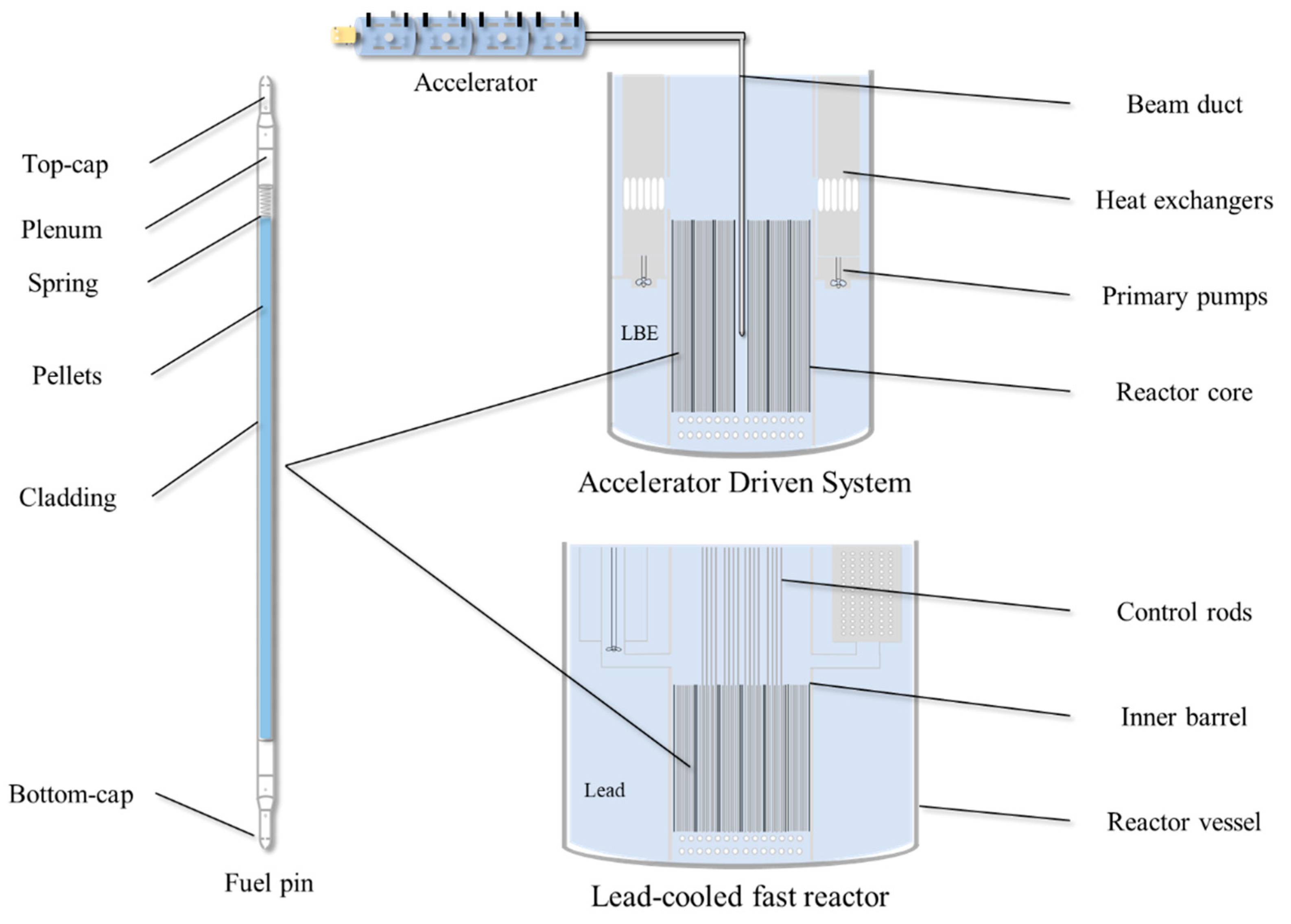
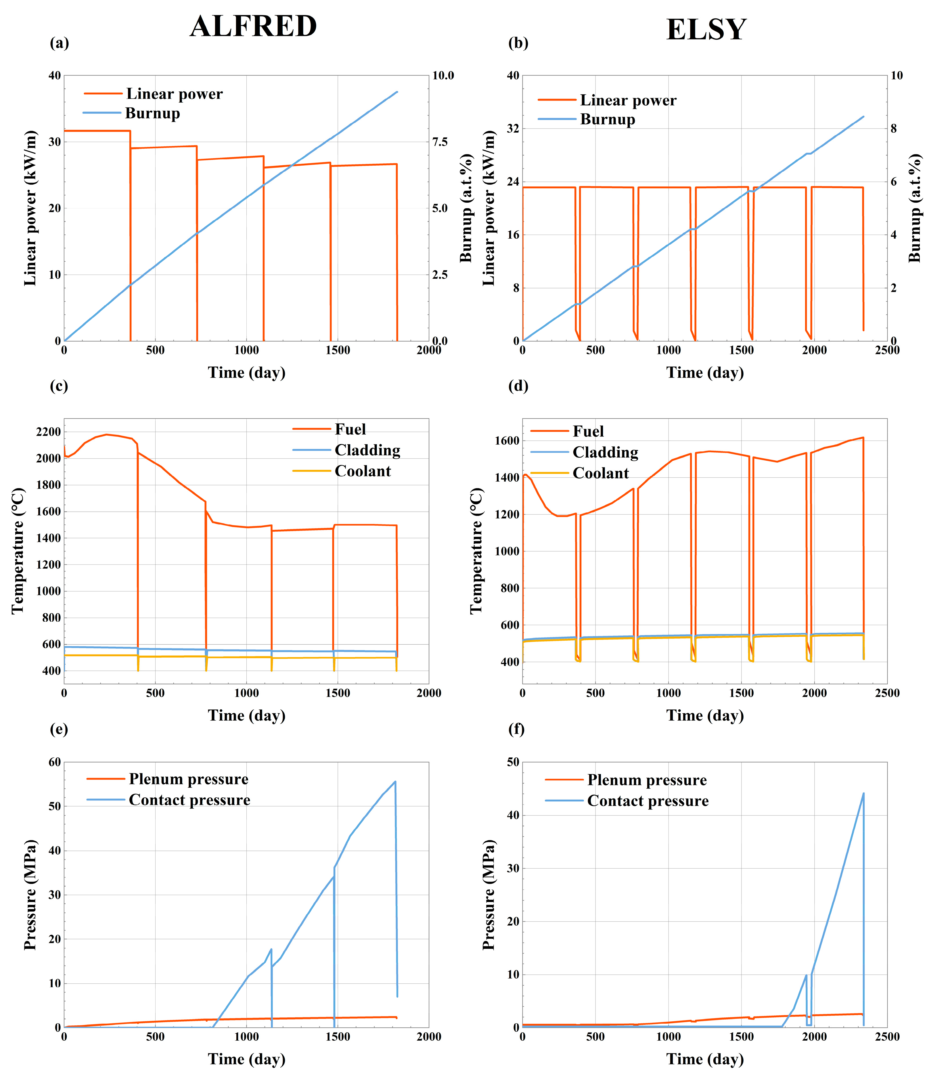
The fuel performance modelling and transient analyses of LFRs are helpful for understanding the relatively realistic environment inside the reactor core and providing a clear image for material applications. In this paper, we took ALFRED and ELSY as reference to illustrate the long-term operating environment for fuel pins. According to the demands of LFRs, the fuel pin will service more than five equivalent full power years and the burnup will exceed 8 a.t.%, while some small modular LFRs intended to use for remote areas or special purposes have higher burnups. The maximum dpa of LFRs ranges from 100 dpa to 150 dpa and causes severe irradiation damage to claddings. Temperatures in the core will experience large increments or decrements during reactor start-up and shut-down, and swing under a long-term operation due to the reactivity changes. The fuel performance analyses of ALFRED indicate that the maximum temperature of the fuel is close to 2200 °C under nominal conditions, and the maximum contact pressure is 55.6 MPa at last because of FCMI, where accelerated creep rupture could occur.
During the long-term steady operation, LFRs could experience a series of transient accidents, in which the reactor parameters change intensely in a short time and may exceed safety limits. Therefore, the safety principles and guidelines have to be elaborated for LFRs. In this paper, transient analyses of DBCs for EFIT and CiADS were summarized and compared, including beam-trip transients, UBOP, ULOF, ULOHS and PLOHS. During frequent 10 s beam-trip of EFIT, the temperature variations of the fuel, the cladding and the coolant were 743 °C, 88 °C and 65 °C, respectively, which is inclined to induce the thermal cyclic fatigue of claddings. Furthermore, under ULOF and ULOHS for both EFIT and CiADS, the coolant temperatures exceeded the design limit of 550 °C with a consequence of irreversible damage of claddings caused by accelerated LBE corrosion.
In addition to satisfying materials design criteria based on in-pile performance, candidate cladding materials for current and proposed future nuclear energy systems must provide adequate resistance to three additional overarching environmental degradation phenomena: temperature dependence, radiation damage and chemical compatibility. Some macroscopical failure behaviors of claddings, such as thermal creep, cyclic fatigue, rupture and ratcheting between fuels and claddings, are temperature-dependent. Radiation damage can produce pronounced irradiation creep, void swelling and hardening due to high densities of nanoscale defects and fission products. Other failure phenomena of LFR claddings can be attributed to chemical compatibility issues, such as lead or LBE corrosion and fuel-cladding chemical interaction (FCCI).
Based on the modelling results, some critical issues need to be addressed in the future:
(i) The fuel cladding mechanical interaction (FCMI) plays an important role in cladding failure, and it is effective to consider delaying FCMI from the initial design of LFRs. In reality, the cladding temperature in LFRs and its variation are relatively low under long-term steady operation, which will not induce large thermal stresses in the cladding before contact. The dominant failure mechanism should be cladding corrosion, and any mechanical effects are not obvious for certain. But once the contact occurs, everything will become complicated. Because large stresses induced by ongoing contact will accelerate creep and make microcracks growing fast until failure, especially with the degradation of cladding mechanical performance due to irradiation and corrosion.
(ii) Which failure mechanism is dominant under different scenarios should be figured out. With regard to frequent beam-trips in ADSs, fatigue under alternating stresses should be the most important issue, and the ratcheting between fuel and cladding tends to be serious after FCMI. But as for ULOF and ULOHS, the cladding temperature increases to a very high value, where all the failure-related behaviors will be accelerated.
(iii) Cladding failure modelling is elaborated with experimental support and performed using FPCs and commercial FEM software. The highly sophisticated descriptions of cladding behaviors should include theoretical knowledge and nonlinear material models. Those unconsidered fatigue mechanisms in this paper, such as liquid metal embrittlement (LME), ratcheting effects, FCCI, either lack suitable mathematical descriptions to couple with multi-physics behaviors or cannot be explained by specifical theories. All of them deserve further research to support quantified simulation and couple with other phenomena. Most importantly, a systematic and demand-driven deployment needs to be conducted from fundamental research to engineering application.

Author Contributions

G.W.: Writing—Original Draft, Resources, Investigation, Formal analysis; Z.W.: Resources, Data curation, Investigation; D.Y.: Supervision, Data Curation, Writing—Review and Editing. All authors have read and agreed to the published version of the manuscript.

Funding

This work was supported by the State Key Research and Development Program of China, Grant No. 2020YFB1902100.

Acknowledgments

We thank Jinxiong Zhou of Xi’an Jiaotong University for providing us with guidance.

Conflicts of Interest

The authors declare that they have no known competing financial interest or personal relationship that could have appeared to influence the work reported in this paper.

Abbreviations

LFRsLead-cooled fast reactors
F/M steelsFerritic/Martensitic steels
AuS steelsAustenitic stainless steels
ODS steelsOxide dispersion strengthened steels
GEN-IVThe International Generation IV Initiative
LWRsLight water reactors
SFRsSodium-cooled fast reactors
LBELead-bismuth eutectic
ADSsAccelerator Driven Systems
Minor actinidesMAs
LLFPsLong-lived fission products
P&TPartitioning and Transmutation
FCMIFuel-cladding mechanical interaction
FCCIFuel-cladding chemical interaction
EFPDEquivalent full power days
BoLBeginning of life
EoLEnd of life
DBCDesign basis conditions
DECDesign extension conditions
UBOPUnprotected beam overpower
ULOFUnprotected loss of flow
ULOHSUnprotected loss of heat sink
RVACSReactor vessel auxiliary cooling system
bccBody-centred cubic
fccFace-centred cubic
dpadisplacements per atom
CDFCumulative damage function
LMPLarson-Miller parameter
FPCsFuel performance codes
UTSUltimate tensile strength
MOXMixed oxide fuel
FEMFinite element method
LMELiquid metal embrittlement

References

  1. OECD/NEA. Accelerator-Driven Systems (ADS) and Fast Reactors (FR) in Advanced Nuclear Fuel Cycles; OECD Publishing: Paris, France, 2002. [Google Scholar]
  2. Nifenecker, H.; Meplan, O.; David, S. Accelerator Driven Subcritical Reactors; Series in Fundamental and Applied Nuclear Physics; Institute of Physics Publishing: Bristol, UK, 2003; ISBN 0-7503-0743-9. [Google Scholar]
  3. Abram, T.; Ion, S. Generation-IV Nuclear Power: A Review of the State of the Science. Energy Policy 2008, 36, 4323–4330. [Google Scholar] [CrossRef]
  4. Locatelli, G.; Mancini, M.; Todeschini, N. Generation IV Nuclear Reactors: Current Status and Future Prospects. Energy Policy 2013, 61, 1503–1520. [Google Scholar]
  5. Ojovan, M.I.; Steinmetz, H.J. Approaches to Disposal of Nuclear Waste. Energies 2022, 15, 7804. [Google Scholar] [CrossRef]
  6. Alwaeli, M.; Mannheim, V. Investigation into the Current State of Nuclear Energy and Nuclear Waste Management—A State-of-the-Art Review. Energies 2022, 15, 4275. [Google Scholar] [CrossRef]
  7. Kurniawan, T.A.; Othman, M.H.D.; Singh, D.; Avtar, R.; Hwang, G.H.; Setiadi, T.; Lo, W. Technological Solutions for Long-Term Storage of Partially Used Nuclear Waste: A Critical Review. Ann. Nucl. Energy 2022, 166, 108736. [Google Scholar]
  8. Buckthorpe, D. Introduction to Generation IV Nuclear Reactors. In Structural Materials for Generation IV Nuclear Reactors; Elsevier: Amsterdam, The Netherlands, 2017; pp. 1–22. [Google Scholar]
  9. Rodriguez, G. Overview of GIF Activities/Updates on Gen IV Systems. In Proceedings of the 15th GIF-IAEA Interface Meeting, Vienna, Austria, 29–30 June 2021. [Google Scholar]
  10. Pioro, I.L.; Rodriguez, G.H. Generation IV International Forum (GIF). In Handbook of Generation IV Nuclear Reactors; Elsevier: Amsterdam, The Netherlands, 2023; pp. 111–132. [Google Scholar]
  11. Alemberti, A. Lead Cooled Fast Reactors. In Reference Module in Earth Systems and Environmental Sciences; Elsevier: Amsterdam, The Netherlands, 2021; pp. 523–544. [Google Scholar]
  12. Alemberti, A.; Smirnov, V.; Smith, C.F.; Takahashi, M. Overview of Lead-Cooled Fast Reactor Activities. Prog. Nucl. Energy 2014, 77, 300–307. [Google Scholar] [CrossRef]
  13. Gonzalez-Romero, E.-M. Impact of Partitioning and Transmutation on the High Level Waste Management. Nucl. Eng. Des. 2011, 241, 3436–3444. [Google Scholar] [CrossRef]
  14. Wallenius, J. Transmutation of Nuclear Waste. Blykalla Böcker Och Spel 2011, 400, 156. [Google Scholar]
  15. Liu, B.; Han, J.; Liu, F.; Sheng, J.; Li, Z. Minor Actinide Transmutation in the Lead-Cooled Fast Reactor. Prog. Nucl. Energy 2020, 119, 103148. [Google Scholar] [CrossRef]
  16. International Atomic Energy Agency. Status of Accelerator Driven Systems Research and Technology Development; IAEA Tecdoc Series; International Atomic Energy Agency: Vienna, Austria, 2015; ISBN 92-0-113919-5. [Google Scholar]
  17. De Bruyn, D.; Larmignat, S.; Hune, A.W.; Mansani, L.; Rimpault, G.; Artioli, C. Accelerator Driven Systems for Transmutation: Main Design Achievements of the XT-ADS and EFIT Systems within the FP6 IP-EUROTRANS Integrated Project. In Proceedings of the ICAPP 2010, San Diego, CA, USA, 13–17 June 2010; Volume 10, pp. 13–17. [Google Scholar]
  18. Tuček, K.; Carlsson, J.; Wider, H. Comparison of Sodium and Lead-Cooled Fast Reactors Regarding Reactor Physics Aspects, Severe Safety and Economical Issues. Nucl. Eng. Des. 2006, 236, 1589–1598. [Google Scholar] [CrossRef]
  19. Murty, K.; Charit, I. Structural Materials for Gen-IV Nuclear Reactors: Challenges and Opportunities. J. Nucl. Mater. 2008, 383, 189–195. [Google Scholar] [CrossRef]
  20. Konings, R.; Stoller, R. Comprehensive Nuclear Materials; Elsevier: Amsterdam, The Netherlands, 2020; ISBN 0-08-102866-0. [Google Scholar]
  21. Olander, D.R. Fundamental Aspects of Nuclear Reactor Fuel Elements: Solutions to Problems; California University: Berkeley, CA, USA, 1976. [Google Scholar]
  22. Khattak, M.; Omran, A.A.B.; Kazi, S.; Khan, M.; ALI, H.M.; Tariq, S.L.; Akram, M.A. A Review of Failure Modes of Nuclear Fuel Cladding. J. Eng. Sci. Technol. 2019, 14, 1520–1541. [Google Scholar]
  23. Kass, S. The Development of the Zircaloys; Westinghouse Electric Corp.: Pittsburgh, PA, USA; Bettis Atomic Power Lab.: West Mifflin, PA, USA, 1962. [Google Scholar]
  24. Mishima, Y.; Aoki, T.; Itō, G.; Kiyooka, S.; Ono, K.; Seki, Y.; Sumitomo, M.; Takao, Z. Behavior of Cladding Tube under Coolant-Loss Accident Conditions. J. Nucl. Sci. Technol. 1966, 3, 72–82. [Google Scholar] [CrossRef]
  25. Pickman, D.O. Zirconium Alloy Performance in Light Water Reactors: A Review of UK and Scandinavian Experience; ASTM International: West Conshohocken, CA, USA, 1994. [Google Scholar]
  26. Garzarolli, F.; Stehle, H.; Steinberg, E. Behavior and Properties of Zircaloys in Power Reactors: A Short Review of Pertinent Aspects in LWR Fuel. ASTM Spec. Tech. Publ. 1996, 1295, 12–34. [Google Scholar]
  27. Cox, B. Some Thoughts on the Mechanisms of In-Reactor Corrosion of Zirconium Alloys. J. Nucl. Mater. 2005, 336, 331–368. [Google Scholar] [CrossRef]
  28. Lewis, B.; Iglesias, F.; Dickson, R.; Williams, A. Overview of High-Temperature Fuel Behaviour with Relevance to CANDU Fuel. J. Nucl. Mater. 2009, 394, 67–86. [Google Scholar]
  29. Alam, T.; Khan, M.K.; Pathak, M.; Ravi, K.; Singh, R.; Gupta, S. A Review on the Clad Failure Studies. Nucl. Eng. Des. 2011, 241, 3658–3677. [Google Scholar] [CrossRef]
  30. Azevedo, C.d.F. Selection of Fuel Cladding Material for Nuclear Fission Reactors. Eng. Fail. Anal. 2011, 18, 1943–1962. [Google Scholar] [CrossRef]
  31. Lorusso, P.; Bassini, S.; Del Nevo, A.; Di Piazza, I.; Giannetti, F.; Tarantino, M.; Utili, M. GEN-IV LFR Development: Status & Perspectives. Prog. Nucl. Energy 2018, 105, 318–331. [Google Scholar]
  32. Serag, E.; Caers, B.; Schuurmans, P.; Lucas, S.; Haye, E. Challenges and Coating Solutions for Wear and Corrosion inside Lead Bismuth Eutectic: A Review. Surf. Coat. Technol. 2022, 441, 128542. [Google Scholar]
  33. Wang, H.; Xiao, J.; Wang, H.; Chen, Y.; Yin, X.; Guo, N. Corrosion Behavior and Surface Treatment of Cladding Materials Used in High-Temperature Lead-Bismuth Eutectic Alloy: A Review. Coatings 2021, 11, 364. [Google Scholar] [CrossRef]
  34. Pioro, I. Handbook of Generation-IV Nuclear Reactors; Woodhead Publishing: Sawston, UK, 2017. [Google Scholar]
  35. Alemberti, A.; Frogheri, M.; Hermsmeyer, S.; Ammirabile, L.; Smirnov, V.; Takahashi, M.; Smith, C.; Wu, Y.; Hwang, I. Lead-Cooled Fast Reactor (LFR) Risk and Safety Assessment White Paper; GEN IV International Forum: Online, 2014; pp. 6–18. [Google Scholar]
  36. Cinotti, L.; Smith, C.F.; Artioli, C.; Grasso, G.; Corsini, G. Lead-Cooled Fast Reactor (LFR) Design: Safety, Neutronics, Thermal Hydraulics, Structural Mechanics, Fuel, Core, and Plant Design. In Handbook of Nuclear Engineering; Lawrence Livermore National Lab.(LLNL): Livermore, CA, USA, 2010. [Google Scholar]
  37. Zrodnikov, A.; Toshinsky, G.; Komlev, O.; Stepanov, V.; Klimov, N. SVBR-100 Module-Type Fast Reactor of the IV Generation for Regional Power Industry. J. Nucl. Mater. 2011, 415, 237–244. [Google Scholar] [CrossRef]
  38. Dragunov, Y.; Lemekhov, V.; Smirnov, V.; Chernetsov, N. Technical Solutions and Development Stages for the BREST-OD-300 Reactor Unit. At. Energy 2012, 113, 70–77. [Google Scholar] [CrossRef]
  39. Alemberti, A.; Carlsson, J.; Malambu, E.; Orden, A.; Struwe, D.; Agostini, P.; Monti, S. European Lead Fast Reactor—ELSY. Nucl. Eng. Des. 2011, 241, 3470–3480. [Google Scholar] [CrossRef]
  40. Alemberti, A. ELFR: The European Lead Fast Reactor. Design, Safety Approach and Safety Characteristics. In Proceedings of the Technical Meeting on Impact of Fukushima Event on Current and Future Fast Reactor Designs, Dresden, Germany, 19–23 March 2012. [Google Scholar]
  41. Alemberti, A.; Frogheri, M.; Mansani, L. The Lead Fast Reactor: Demonstrator (ALFRED) and ELFR Design. In Proceedings of the FR13: International Conference on Fast Reactors and Related Fuel Cycles: Safe Technologies and Sustainable Scenarios, Paris France, 4–7 March 2013. [Google Scholar]
  42. Grasso, G.; Petrovich, C.; Mattioli, D.; Artioli, C.; Sciora, P.; Gugiu, D.; Bandini, G.; Bubelis, E.; Mikityuk, K. The Core Design of ALFRED, a Demonstrator for the European Lead-Cooled Reactors. Nucl. Eng. Des. 2014, 278, 287–301. [Google Scholar] [CrossRef]
  43. Wallenius, J.; Qvist, S.; Mickus, I.; Bortot, S.; Szakalos, P.; Ejenstam, J. Design of SEALER, a Very Small Lead-Cooled Reactor for Commercial Power Production in off-Grid Applications. Nucl. Eng. Des. 2018, 338, 23–33. [Google Scholar]
  44. Smith, C.F.; Halsey, W.G.; Brown, N.W.; Sienicki, J.J.; Moisseytsev, A.; Wade, D.C. SSTAR: The US Lead-Cooled Fast Reactor (LFR). J. Nucl. Mater. 2008, 376, 255–259. [Google Scholar] [CrossRef]
  45. Rubbia, C. A Comparison of the Safety and Environmental Advantages of the Energy Amplifier and of Magnetic Confinement Fusion; Document CERN/AT/95-58 (ET); European Organization for Nuclear Research: Meyrin, Switzerland, 1995. [Google Scholar]
  46. Mueller, A.C. Nuclear Waste Incineration and Accelerator Aspects from the European PDS-XADS Study. Nucl. Phys. A 2005, 751, 453–468. [Google Scholar] [CrossRef]
  47. Artioli, C.; Chen, X.; Gabrielli, F.; Glinatsis, G.; Liu, P.; Maschek, W.; Petrovich, C.; Rineiski, A.; Sarotto, M.; Schikorr, M. Minor Actinide Transmutation in ADS: The EFIT Core Design. In Proceedings of the International Conference on the Physics of Reactors, Interlaken, Switzerland, 14–19 September 2008. [Google Scholar]
  48. Mansani, L.; Artioli, C.; Schikorr, M.; Rimpault, G.; Angulo, C.; Bruyn, D.D. The European Lead-Cooled EFIT Plant: An Industrial-Scale Accelerator-Driven System for Minor Actinide Transmutation—I. Nucl. Technol. 2012, 180, 241–263. [Google Scholar] [CrossRef]
  49. Abderrahim, H.A.; Baeten, P.; De Bruyn, D.; Fernandez, R. MYRRHA–A Multi-Purpose Fast Spectrum Research Reactor. Energy Convers. Manag. 2012, 63, 4–10. [Google Scholar] [CrossRef]
  50. Gu, L.; Su, X. Latest Research Progress for LBE Coolant Reactor of China Initiative Accelerator Driven System Project. Front. Energy 2021, 15, 810–831. [Google Scholar] [CrossRef]
  51. Luzzi, L.; Cammi, A.; Di Marcello, V.; Lorenzi, S.; Pizzocri, D.; Van Uffelen, P. Application of the TRANSURANUS Code for the Fuel Pin Design Process of the ALFRED Reactor. Nucl. Eng. Des. 2014, 277, 173–187. [Google Scholar] [CrossRef]
  52. Sobolev, V.; Malambu, E.; Abderrahim, H.A. Design of a Fuel Element for a Lead-Cooled Fast Reactor. J. Nucl. Mater. 2009, 385, 392–399. [Google Scholar] [CrossRef]
  53. Grasso, G.; Petrovich, C.; Mikityuk, K.; Mattioli, D.; Manni, F.; Gugiu, D. Demonstrating the Effectiveness of the European LFR Concept: The ALFRED Core Design. In Proceedings of the International Conference on Fast Reactors and Related Fuel Cycles: Safe Technologies and Sustainable Scenarios (FR13), Paris, France, 4–7 March 2013. [Google Scholar]
  54. Papin, J. Behavior of Fast Reactor Fuel during Transient and Accident Conditions; Elsevier: Amsterdam, The Netherlands, 2019. [Google Scholar]
  55. Liu, P.; Chen, X.; Rineiski, A.; Maschek, W. Transient Analyses of the 400MWth-Class EFIT Accelerator Driven Transmuter with the Multi-Physics Code: SIMMER-III. Nucl. Eng. Des. 2010, 240, 3481–3494. [Google Scholar] [CrossRef]
  56. Wang, G.; Wallenius, J.; Yu, R.; Jiang, W.; Zhang, L.; Sheng, X.; Yun, D.; Gu, L. Transient Analyses for China Initiative Accelerator Driven System Using the Extended BELLA Code. Ann. Nucl. Energy 2023, 190, 109892. [Google Scholar] [CrossRef]
  57. Bandini, G.; Casamirra, M.; Castiglia, F.; Mansani, L.; Meloni, P.; Polidori, M. Preliminary T/H and Transient Analyses for EFIT Reactor Design. In Proceedings of the ICAPP 2007, Nice, France, 13–18 May 2007; Volume 7. [Google Scholar]
  58. Maschek, W.; Rineiski, A.; Suzuki, T.; Wang, S.; Mori, M.; Wiegner, E.; Wilhelm, D.; Kretzschmar, F.; Tobita, Y.; Yamano, H. SIMMER-III and SIMMER-IV Safety Code Development for Reactors with Transmutation Capability. In Proceedings of the Mathematics and Computation, Supercomputing, Reactor Physics and Biological Applications, Avignon, France, 12–15 September 2005. [Google Scholar]
  59. Tobita, Y.; Kondo, S.; Yamano, H.; Morita, K.; Maschek, W.; Coste, P.; Cadiou, T. The Development of SIMMER-III, an Advanced Computer Program for LMFR Safety Analysis, and Its Application to Sodium Experiments. Nucl. Technol. 2006, 153, 245–255. [Google Scholar] [CrossRef]
  60. Bortot, S.; Suvdantsetseg, E.; Wallenius, J. BELLA: A Multi-Point Dynamics Code for Safety-Informed Design of Fast Reactors. Ann. Nucl. Energy 2015, 85, 228–235. [Google Scholar] [CrossRef]
  61. Wang, G.; Gu, L.; Yun, D. Preliminary Multi-Physics Performance Analysis and Design Evaluation of UO2 Fuel for LBE-Cooled Subcritical Reactor of China Initiative Accelerator Driven System. Front. Energy Res. 2021, 9, 732801. [Google Scholar] [CrossRef]
  62. Luzzi, L.; Vettraino, F.; Calabrese, R. ADS-demo fuel rod performance analysis. In Proceedings of the Global Environment and Nuclear Energy Systems/Advanced Nuclear Power Plants International Conference (GENES4/ANP2003), Kyoto, Japan, 15–19 September 2003; p. 1155. [Google Scholar]
  63. Series, I.N.E. Structural Materials for Liquid Metal Cooled Fast Reactor Fuel Assemblies–Operational Behaviour; Report No. NF; International Atomic Energy Agency (IAEA): Vienna, Austria, 2012. [Google Scholar]
  64. Gong, X.; Short, M.P.; Auger, T.; Charalampopoulou, E.; Lambrinou, K. Environmental Degradation of Structural Materials in Liquid Lead-and Lead-Bismuth Eutectic-Cooled Reactors. Prog. Mater. Sci. 2022, 126, 100920. [Google Scholar]
  65. Fazio, C.; Sobolev, V.; Aerts, A.; Gavrilov, S.; Lambrinou, K.; Schuurmans, P.; Gessi, A.; Agostini, P.; Ciampichetti, A.; Martinelli, L. Handbook on Lead-Bismuth Eutectic Alloy and Lead Properties, Materials Compatibility, Thermal-Hydraulics and Technologies-2015 Edition; Organisation for Economic Co-Operation and Development: Paris, France, 2015. [Google Scholar]
  66. Maziasz, P.J.; Busby, J.T. Properties of Austenitic Stainless Steels for Nuclear Reactor Applications; Oak Ridge National Lab. (ORNL): Oak Ridge, TN, USA, 2012. [Google Scholar]
  67. Raj, B.; Vijayalakshmi, M. Ferritic Steels and Advanced Ferritic–Martensitic Steels. Compr. Nucl. Mater. 2012, 97–121. [Google Scholar] [CrossRef]
  68. Klueh, R.; Shingledecker, J.; Swindeman, R.; Hoelzer, D. Oxide Dispersion-Strengthened Steels: A Comparison of Some Commercial and Experimental Alloys. J. Nucl. Mater. 2005, 341, 103–114. [Google Scholar] [CrossRef]
  69. Lamon, J. Properties of Characteristics of SiC and SiC/SiC Composites; Laboratoire de Mécanique et Technologie: Cachan, France, 2019. [Google Scholar]
  70. El-Genk, M.S.; Tournier, J.-M. A Review of Refractory Metal Alloys and Mechanically Alloyed-Oxide Dispersion Strengthened Steels for Space Nuclear Power Systems. J. Nucl. Mater. 2005, 340, 93–112. [Google Scholar] [CrossRef]
  71. Raman, L.; Gothandapani, K.; Murty, B. Austenitic Oxide Dispersion Strengthened Steels: A Review. Def. Sci. J. 2016, 66, 316–322. [Google Scholar] [CrossRef]
  72. Verhiest, K.; Almazouzi, A.; De Wispelaere, N.; Petrov, R.; Claessens, S. Development of Oxides Dispersion Strengthened Steels for High Temperature Nuclear Reactor Applications. J. Nucl. Mater. 2009, 385, 308–311. [Google Scholar] [CrossRef]
  73. Leonard, K.J. Radiation Effects in Refractory Metals and Alloys (Chapter 88); Oak Ridge National Lab. (ORNL): Oak Ridge, TN, USA, 2012. [Google Scholar]
  74. Daghbouj, N.; Li, B.; Callisti, M.; Sen, H.; Karlik, M.; Polcar, T. Microstructural Evolution of Helium-Irradiated 6H–SiC Subjected to Different Irradiation Conditions and Annealing Temperatures: A Multiple Characterization Study. Acta Mater. 2019, 181, 160–172. [Google Scholar]
  75. Mondal, K.; Nuñez III, L.; Downey, C.M.; Van Rooyen, I.J. Thermal Barrier Coatings Overview: Design, Manufacturing, and Applications in High-Temperature Industries. Ind. Eng. Chem. Res. 2021, 60, 6061–6077. [Google Scholar] [CrossRef]
  76. Gong, X.; Li, R.; Sun, M.; Ren, Q.; Liu, T.; Short, M.P. Opportunities for the LWR ATF Materials Development Program to Contribute to the LBE-Cooled ADS Materials Qualification Program. J. Nucl. Mater. 2016, 482, 218–228. [Google Scholar] [CrossRef]
  77. Yvon, P.; Carré, F. Structural Materials Challenges for Advanced Reactor Systems. J. Nucl. Mater. 2009, 385, 217–222. [Google Scholar] [CrossRef]
  78. Anderoglu, O.; Byun, T.S.; Toloczko, M.; Maloy, S.A. Mechanical Performance of Ferritic Martensitic Steels for High Dose Applications in Advanced Nuclear Reactors. Metall. Mater. Trans. A 2013, 44, 70–83. [Google Scholar] [CrossRef]
  79. Alamo, A.; Bertin, J.; Shamardin, V.; Wident, P. Mechanical Properties of 9Cr Martensitic Steels and ODS-FeCr Alloys after Neutron Irradiation at 325 C up to 42 Dpa. J. Nucl. Mater. 2007, 367, 54–59. [Google Scholar] [CrossRef]
  80. Hales, J.D.; Williamson, R.L.; Novascone, S.R.; Pastore, G.; Spencer, B.W.; Stafford, D.S.; Gamble, K.A.; Perez, D.M.; Liu, W. BISON Theory Manual the Equations behind Nuclear Fuel Analysis; Idaho National Lab.: Idaho Falls, ID, USA, 2016. [Google Scholar]
  81. Xu, C.; Hackett, M. TerraPower HT9 Mechanical and Thermal Creep Properties; Springer: Berlin/Heidelberg, Germany, 2017; pp. 95–102. [Google Scholar]
  82. Aoto, K.; Dufour, P.; Hongyi, Y.; Glatz, J.P.; Kim, Y.; Ashurko, Y.; Hill, R.; Uto, N. A Summary of Sodium-Cooled Fast Reactor Development. Prog. Nucl. Energy 2014, 77, 247–265. [Google Scholar]
  83. Daghbouj, N.; Callisti, M.; Sen, H.; Karlik, M.; Čech, J.; Vronka, M.; Havránek, V.; Čapek, J.; Minárik, P.; Bábor, P. Interphase Boundary Layer-Dominated Strain Mechanisms in Cu+ Implanted Zr-Nb Nanoscale Multilayers. Acta Mater. 2021, 202, 317–330. [Google Scholar] [CrossRef]
  84. Daghbouj, N.; Sen, H.; Callisti, M.; Vronka, M.; Karlik, M.; Duchoň, J.; Čech, J.; Havránek, V.; Polcar, T. Revealing Nanoscale Strain Mechanisms in Ion-Irradiated Multilayers. Acta Mater. 2022, 229, 117807. [Google Scholar] [CrossRef]
  85. Zinkle, S.J.; Was, G. Materials Challenges in Nuclear Energy. Acta Mater. 2013, 61, 735–758. [Google Scholar] [CrossRef]
  86. Allen, T.; Sridharan, K.; Tan, L.; Windes, W.; Cole, J.; Crawford, D.; Was, G.S. Materials Challenges for Generation IV Nuclear Energy Systems. Nucl. Technol. 2008, 162, 342–357. [Google Scholar] [CrossRef]
  87. ASTM E521-96; Standard Practice for Neutron Damage Simulation by Charged-Particle Irradiation. ASTM International: West Conshohocken, PA, USA, 2000.
  88. Norgett, M.; Robinson, M.; Torrens, I.M. A Proposed Method of Calculating Displacement Dose Rates. Nucl. Eng. Des. 1975, 33, 50–54. [Google Scholar] [CrossRef]
  89. Li, B.; Sen, H.; Daghbouj, N.; AlMotasem, A.T.; Lorinčík, J.; Karlik, M.; Ge, F.; Zhang, L.; Sofer, Z.; Elantyev, I. Thermal Behavior of Iron in 6H-SiC: Influence of He-Induced Defects. Scr. Mater. 2022, 218, 114805. [Google Scholar] [CrossRef]
  90. Daghbouj, N.; AlMotasem, A.; Vesely, J.; Li, B.; Sen, H.; Karlik, M.; Lorinčík, J.; Ge, F.; Zhang, L.; Krsjak, V. Microstructure Evolution of Iron Precipitates in (Fe, He)-Irradiated 6H-SiC: A Combined TEM and Multiscale Modeling. J. Nucl. Mater. 2023, 584, 154543. [Google Scholar] [CrossRef]
  91. Ashby, M.F. A First Report on Deformation-Mechanism Maps. Acta Metall. 1972, 20, 887–897. [Google Scholar] [CrossRef]
  92. Meyers, M.A.; Chawla, K.K. Mechanical Behavior of Materials; Cambridge University Press: Cambridge, UK, 2008; ISBN 1-107-39418-X. [Google Scholar]
  93. Gavoille, P.; Courcelle, A.; Seran, J.; Averty, X.; Bourdiliau, B.; Provitina, O.; Garat, V.; Verwaerde, D. Mechanical Properties of Cladding and Wrapper Materials for the ASTRID Fast-Reactor Project. In Proceedings of the FR13: International Conference on Fast Reactors and Related Fuel Cycles: Safe Technologies and Sustainable Scenarios, Paris, France, 4–7 March 2013. [Google Scholar]
  94. Filacchioni, G.; De Angelis, U.; Ferrara, D.; Pilloni, L. Mechanical and Structural Behaviour of the Second Double Stabilized Stainless Steels Generation. In Fast Reactor Core and Fuel Structural Behaviour; Thomas Telford Publishing: London, UK, 1990; pp. 255–261. [Google Scholar]
  95. de Bellefon, G.M.; Bertsch, K.; Chancey, M.; Wang, Y.; Thoma, D. Influence of Solidification Structures on Radiation-Induced Swelling in an Additively-Manufactured Austenitic Stainless Steel. J. Nucl. Mater. 2019, 523, 291–298. [Google Scholar] [CrossRef]
  96. Waltar, A.E.; Todd, D.R.; Tsvetkov, P.V. Fast Spectrum Reactors; Springer: Berlin/Heidelberg, Germany, 2011; ISBN 1-4419-9572-2. [Google Scholar]
  97. Dubuisson, P. Core Structural Materials-Feedback Experience from PHENIX. In Proceedings of the Technical Meeting on Design, Manufacturing and Irradiation Behaviour of Fast Reactor Fuel, Obninsk, Russian, 30 May–3 June 2011. [Google Scholar]
  98. Paaren, K.M.; Lybeck, N.; Mo, K.; Medvedev, P.; Porter, D. Cladding Profilometry Analysis of Experimental Breeder Reactor-Ii Metallic Fuel Pins with Ht9, D9, and Ss316 Cladding. Energies 2021, 14, 515. [Google Scholar] [CrossRef]
  99. Larson, F.R.; Miller, J. A Time-Temperature Relationship for Rupture and Creep Stresses. Trans. Am. Soc. Mech. Eng. 1952, 74, 765–771. [Google Scholar] [CrossRef]
  100. Daghbouj, N.; Sen, H.; Čížek, J.; Lorinčík, J.; Karlík, M.; Callisti, M.; Čech, J.; Havránek, V.; Li, B.; Krsjak, V. Characterizing Heavy Ions-Irradiated Zr/Nb: Structure and Mechanical Properties. Mater. Des. 2022, 219, 110732. [Google Scholar] [CrossRef]
  101. Zhang, J. Long-Term Behaviors of Oxide Layer in Liquid Lead–Bismuth Eutectic (LBE), Part I: Model Development and Validation. Oxid. Met. 2013, 80, 669–685. [Google Scholar] [CrossRef]
  102. Zhang, J. Long-Term Behaviors of Oxide Layer in Liquid Lead–Bismuth Eutectic (LBE), Part II: Model Applications. Oxid. Met. 2014, 81, 597–615. [Google Scholar] [CrossRef]
  103. Van Uffelen, P.; Hales, J.; Li, W.; Rossiter, G.; Williamson, R. A Review of Fuel Performance Modelling. J. Nucl. Mater. 2019, 516, 373–412. [Google Scholar]
  104. Aybar, H.S.; Ortego, P. A Review of Nuclear Fuel Performance Codes. Prog. Nucl. Energy 2005, 46, 127–141. [Google Scholar] [CrossRef]
  105. Jankus, V.; Weeks, R. LIFE-II—A Computer Analysis of Fast-Reactor Fuel-Element Behavior as a Function of Reactor Operating History. Nucl. Eng. Des. 1972, 18, 83–96. [Google Scholar] [CrossRef]
  106. Matthews, J.R. The Basis of the TRAFIC Fuel Performance Code; UKAEA Atomic Energy Research Establishment: Abingdon, UK, 1982. [Google Scholar]
  107. Matthews, J.R.; Thetford, R.; Wood, M.H. The Application of the TRAFIC Fuel Performance Code to Steady and Transient Conditions. In Proceedings of the Nuclear Fuel Performance, Stratford-upon-Avon, UK, 25–29 March 1985; pp. 301–307. [Google Scholar]
  108. Lassmann, K.; Schubert, A.; Van Uffelen, P.; Gyori, C. TRANSURANUS Handbook Copyright© 1975–2014; Institute for Transuranium Elements: Karlsruhe, Germany, 2019. [Google Scholar]
  109. Hwang, W.; Nam, C.; Byun, T.S.; Kim, Y.C. MACSIS: A Metallic Fuel Performance Analysis Code for Simulating in-Reactor Behavior under Steady-State Conditions. Nucl. Technol. 1998, 123, 130–141. [Google Scholar] [CrossRef]
  110. Ozawa, T.; Abe, T. Development and Verifications of Fast Reactor Fuel Design Code CEPTAR. Nucl. Technol. 2006, 156, 39–55. [Google Scholar] [CrossRef]
  111. Karahan, A.; Andrews, N.C. Extended Fuel Swelling Models and Ultra High Burn-up Fuel Behavior of U–Pu–Zr Metallic Fuel Using FEAST-METAL. Nucl. Eng. Des. 2013, 258, 26–34. [Google Scholar] [CrossRef]
  112. Lainet, M.; Michel, B.; Dumas, J.-C.; Pelletier, M.; Ramière, I. GERMINAL, a Fuel Performance Code of the PLEIADES Platform to Simulate the in-Pile Behaviour of Mixed Oxide Fuel Pins for Sodium-Cooled Fast Reactors. J. Nucl. Mater. 2019, 516, 30–53. [Google Scholar]
  113. Veshchunov, M.S.; Boldyrev, A.V.; Kuznetsov, A.V.; Ozrin, V.D.; Seryi, M.S.; Shestak, V.E.; Tarasov, V.I.; Norman, G.E.; Kuksin, A.Y.; Pisarev, V.V. Development of the Advanced Mechanistic Fuel Performance and Safety Code Using the Multi-Scale Approach. Nucl. Eng. Des. 2015, 295, 116–126. [Google Scholar] [CrossRef]
  114. Okawa, T.; Tatewaki, I.; Ishizu, T.; Endo, H.; Tsuboi, Y.; Saitou, H. Fuel Behavior Analysis Code FEMAXI-FBR Development and Validation for Core Disruptive Accident. Prog. Nucl. Energy 2015, 82, 80–85. [Google Scholar] [CrossRef]
  115. WANG, G.; GU, L.; YU, R.; WANG, T.; WANG, Z.; YUAN, H.; YUN, D. Development and Preliminary Verification of Oxide Fuel Performance Analysis Code FUTURE for Lead-Based Fast Reactor. At. Energy Sci. Technol. 2022, 56, 1328. [Google Scholar]
  116. Gaston, D.; Newman, C.; Hansen, G.; Lebrun-Grandie, D. MOOSE: A Parallel Computational Framework for Coupled Systems of Nonlinear Equations. Nucl. Eng. Des. 2009, 239, 1768–1778. [Google Scholar] [CrossRef]
  117. Michel, B.; Sercombe, J.; Nonon, C.; Fandeur, O. Modeling of Pellet Cladding Interaction; Elsevier Inc.: Amsterdam, The Netherlands, 2012; Volume 3, ISBN 978-0-08-056033-5. [Google Scholar]
Figure 1. Schematics of a fuel pin, an ADS and an LFR.
Metals 13 01524 g001
Figure 2. Fuel performance modelling for ALFRED and ELSY. (a,c,e) for ALFRED; (b,d,f) for ELSY [51,52].
Metals 13 01524 g002
Figure 3. Transient analyses for EFIT [52,57].
Metals 13 01524 g003
Figure 4. Transient analyses for CiADS [56].
Metals 13 01524 g004
Figure 5. The oxide thicknesses of ELSY and CiADS [52,56].
Metals 13 01524 g005
Figure 6. Multiphysics behaviors of the fuel pin.
Metals 13 01524 g006
Figure 7. Structural details of claddings under long-term operation.
Metals 13 01524 g007
Table 1. Main parameters of LFRs and ADSs.
ProgramPower (MWth)CladdingCoolantCore Inlet Temperature (°C)Core Outlet Temperature (°C)Velocity (m/s)
LFRELSY1500T91Lead4004801.6
ALFRED30015-15TiLead4004801.4
BREST-300700EP823Lead4205401.8
SVBR280EP823Lead3454951.53
SEALER14015-15TiLead4205501.6
SSTAR45HT9Lead4205670.896
ADSEFIT300T91Lead4004801.2
XT-ADS57T91LBE3004002.0
MYRRHA100T91LBE2703602.0
CiADS1015-15TiLBE2803800.355
Table 2. Indicative design limits for LFRs [51].
ParametersIndications
Peak fuel temperature<2000 °C
Peak cladding temperature<550 °C
Plenum pressure<5 MPa
Maximum coolant velocity<2 m/s
Cladding linear strain<3%
Thermal creep strain<0.2% or <1%
Total creep strain<3%
Cumulative damage function<0.2 or <0.3
Swelling strain<5%
Instantaneous plastic strain<0.5%
Table 3. Nominal chemical composition of typical F/M and Austenitic stainless steels (wt.% balance is Fe) [64].
SteelHT9T91EP823316L1.4970D9
C0.170.10.160.030.10.052
Cr11.58.9911.717.01513.8
Ni0.50.110.6610–141515.2
Mn0.60.380.551.81.51.74
Mo-0.890.742.01.21.5
Si0.40.221.090.60.40.92
W--0.6---
Nb-0.06----
V-0.210.3---
B---0.0020.005-
Ti----0.50.23
P-----0.003
Table 4. Thermal and mechanical parameters of HT9 [80,81].
ParameterCorrelation
Thermal expansion (%) ε t h = 0.2191 + 5.678 × 10 4 T K + 8.111 × 10 7 T K 2 2.576 × 10 10 T K 3
Density (kg/m3) ρ = 7900 · 1 1 + ε t h 3
Specific heat (J/kg/K) C p = T K 500 6 + 500   ,   T < 800 K 3 T K 800 5 + 550 , T 800 K
Thermal conductivity (W/m/K) λ = 17.622 + 2.42 × 10 2 T K 1.696 × 10 5 T K 2 ,   T < 1030 K 12.027 + 1.218 × 10 2 T K 2 ,   T 1030 K
Young’s modulus (MPa) E = 2.345 × 10 5 79.659 T K 0.01317 T K 2
Poisson ratio ν = 0.222 + 2.643 × 10 4 T K 2 2.029 × 10 7 T K 2
Rupture strain (%) ε r u p t = 6.672 + 0.051 T K 2.08 × 10 4 T K 2 + 2.59 × 10 7 T K 2
Table 5. Thermal and mechanical parameters of 15-15Ti [51].
ParameterCorrelation
Thermal expansion (%) ε t h = 3.101 × 10 4 + 1.545 × 10 5 T + 2.75 × 10 9 T 2
Density (kg/m3) ρ = 7900 · 1 1 + ε t h 3
Specific heat (J/kg/K) c p = 431 + 0.77 T K + 8.72 × 10 5 T K 2
Thermal conductivity (W/m/K) λ = 13.95 + 0.01163 T ( )
Young’s modulus (GPa) E = 202.7 81.67 × 10 3 T ( )
Poisson ratio ν = 0.277 + 6 × 10 5 T ( )
Rupture strain (%) ε r u p t = 8 + 4.74 × 10 3 T 500 + 6.2 × 10 3 T 500 2
Table 6. Fuel performance codes for fast reactors.
Fuel Performance CodeTimeInstitute (Country)
LIFE1970sArgonne National Laboratory (United States)
TRAFIC1980sHarwell Laboratory (United Kingdom)
TRANSURANUS1980sEuropean Institute for Transuranium Elements (Germany)
MACSIS1990sAtomic Energy Research Institute (Korea)
CEPTAR2000sJapan Atomic Energy Agency (Japan)
FEAST2000sMassachusetts Institute of Technology (United States)
GERMINAL2010sCommission of Alternative and Atomic Energies (France)
BERKUT2010sRussian Academy of Sciences (Russia)
FEMAXI-FBR2010sAtomic Energy Research Institute (Japan)
FUTURE2010sChinese Academy of Sciences (China)
Disclaimer/Publisher’s Note: The statements, opinions and data contained in all publications are solely those of the individual author(s) and contributor(s) and not of MDPI and/or the editor(s). MDPI and/or the editor(s) disclaim responsibility for any injury to people or property resulting from any ideas, methods, instructions or products referred to in the content.

