
Test on Compressive Performance of Hollow Concrete-Filled Sandwich Circular Steel Tubes Connected by Thread
Abstract
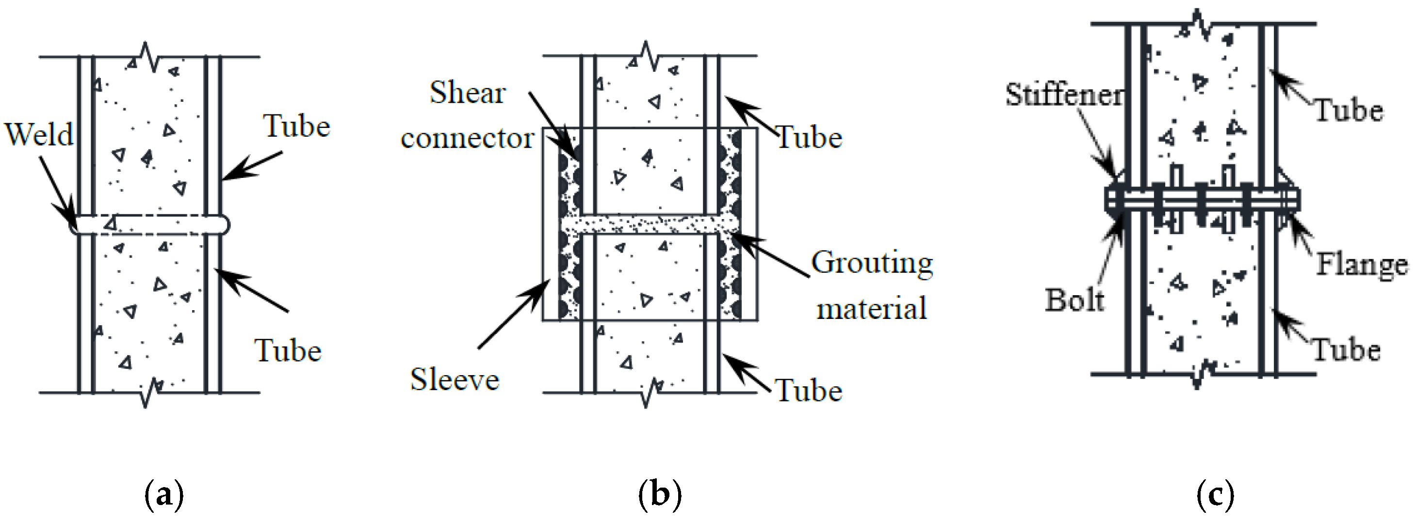
:1. Introduction
2. Specimen Design and Raw Material Performance
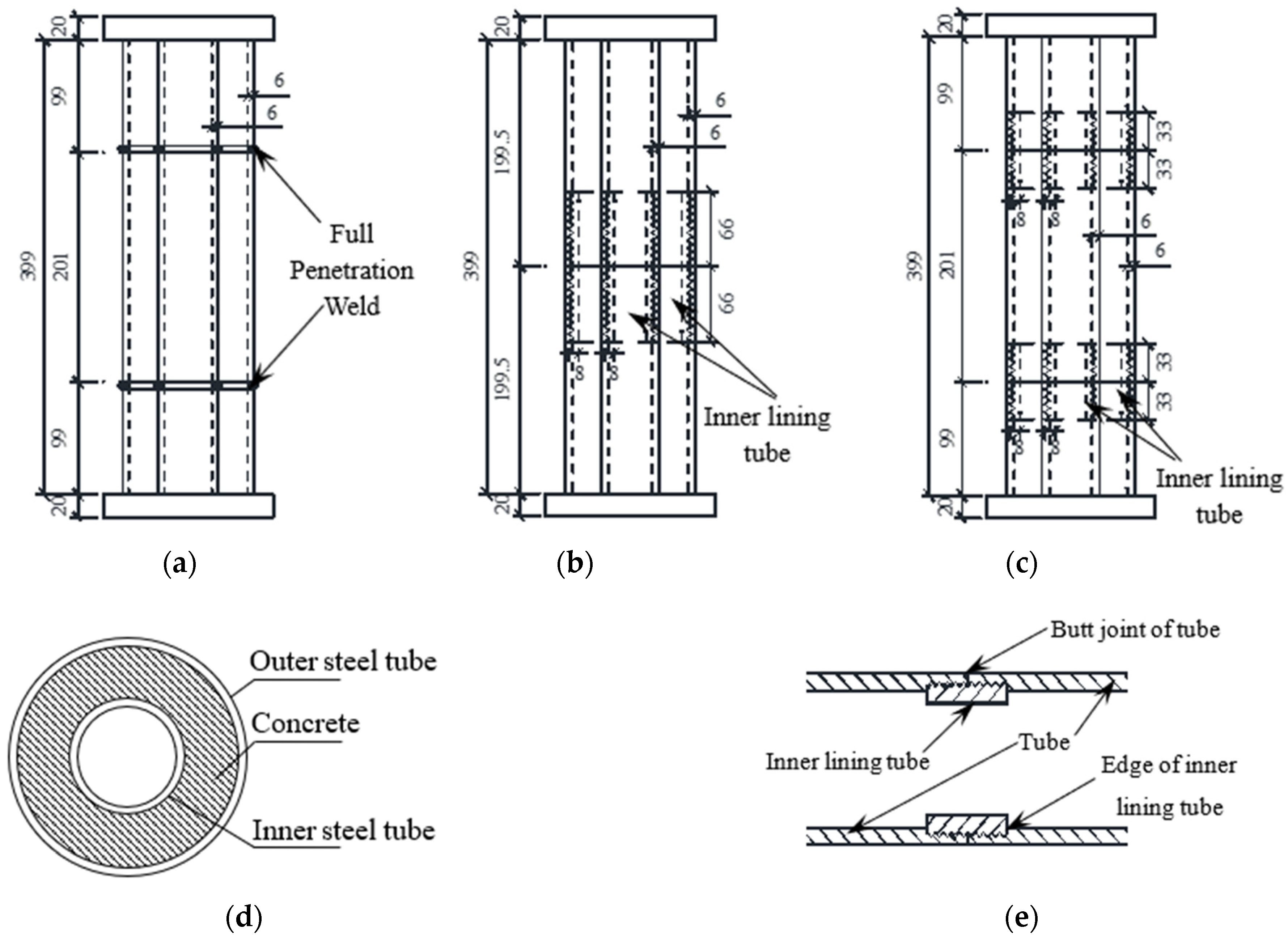
2.1. Specimen Design
2.2. Material Properties
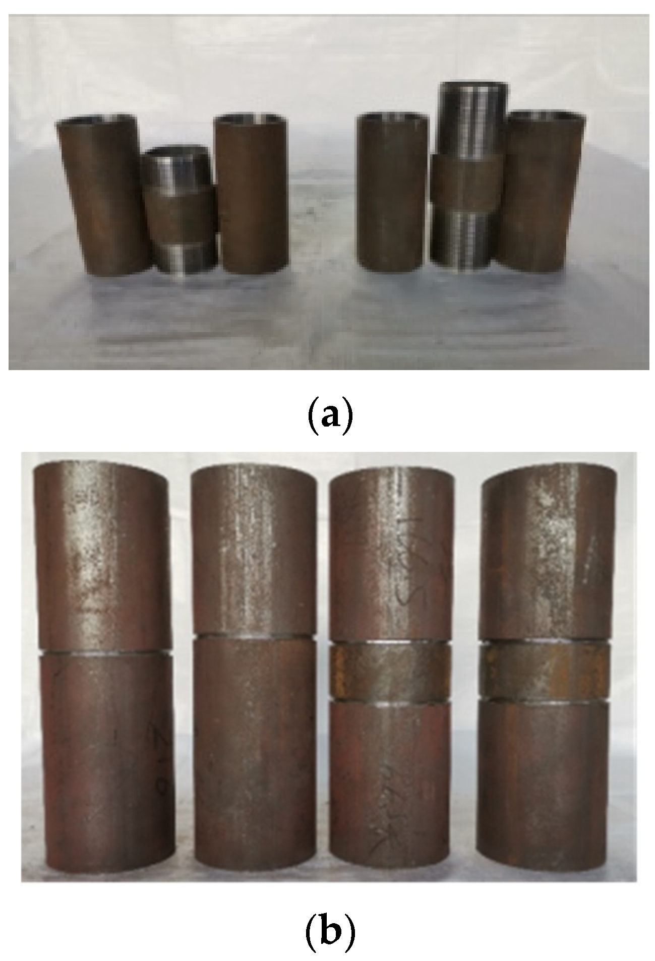
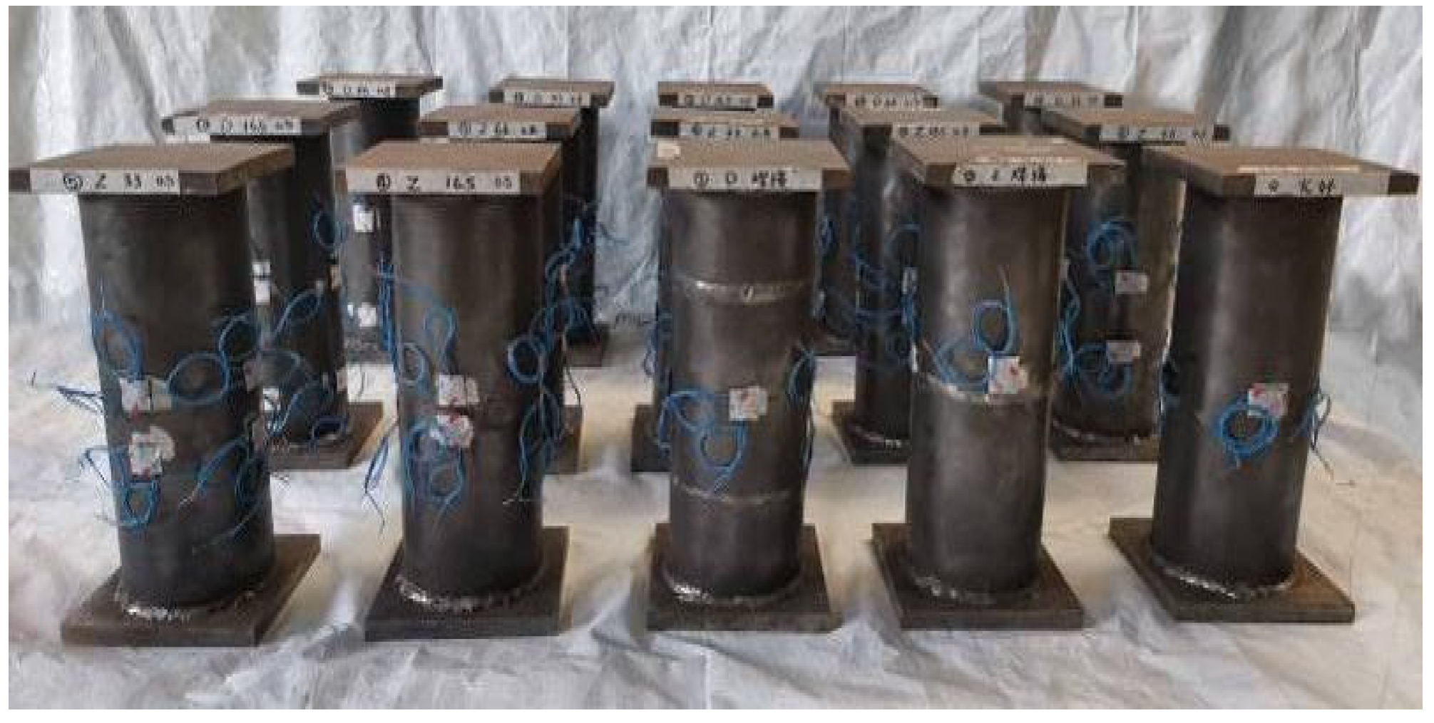
2.3. Preparation of Specimens
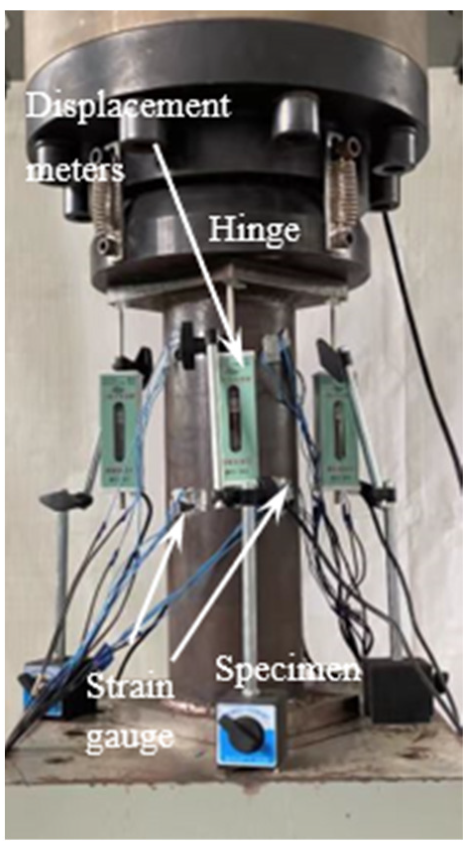
2.4. Loading and Measurement
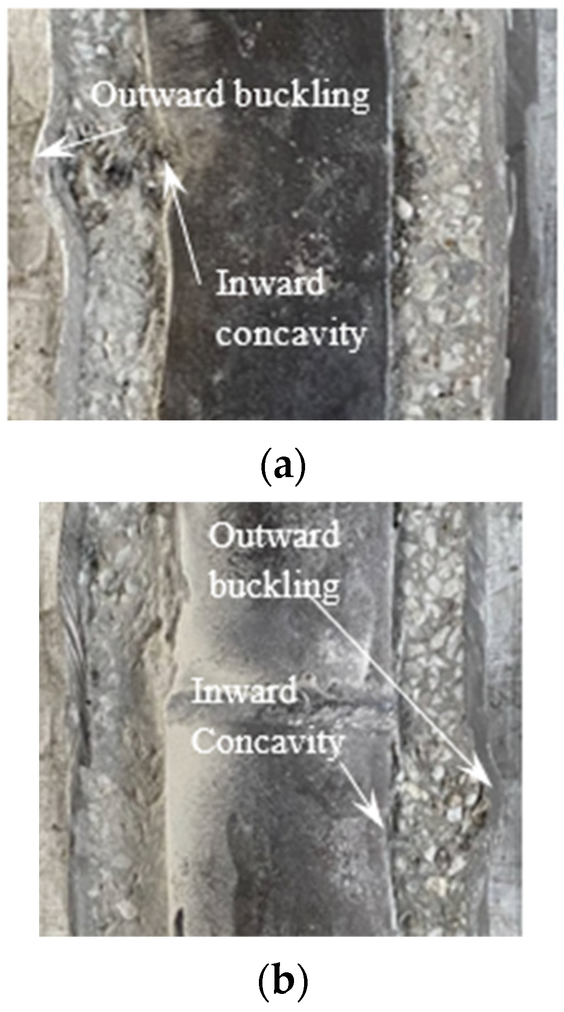
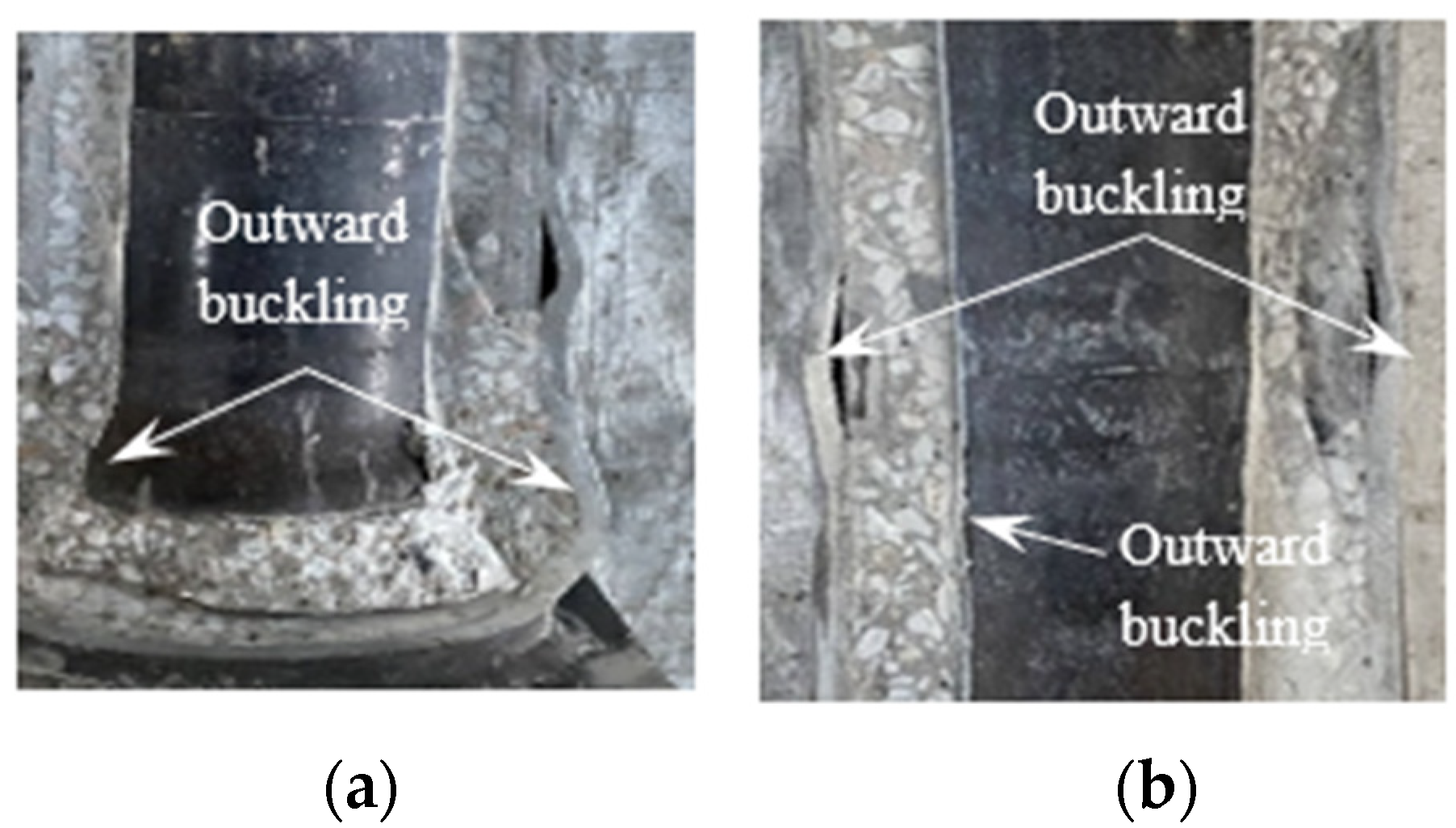
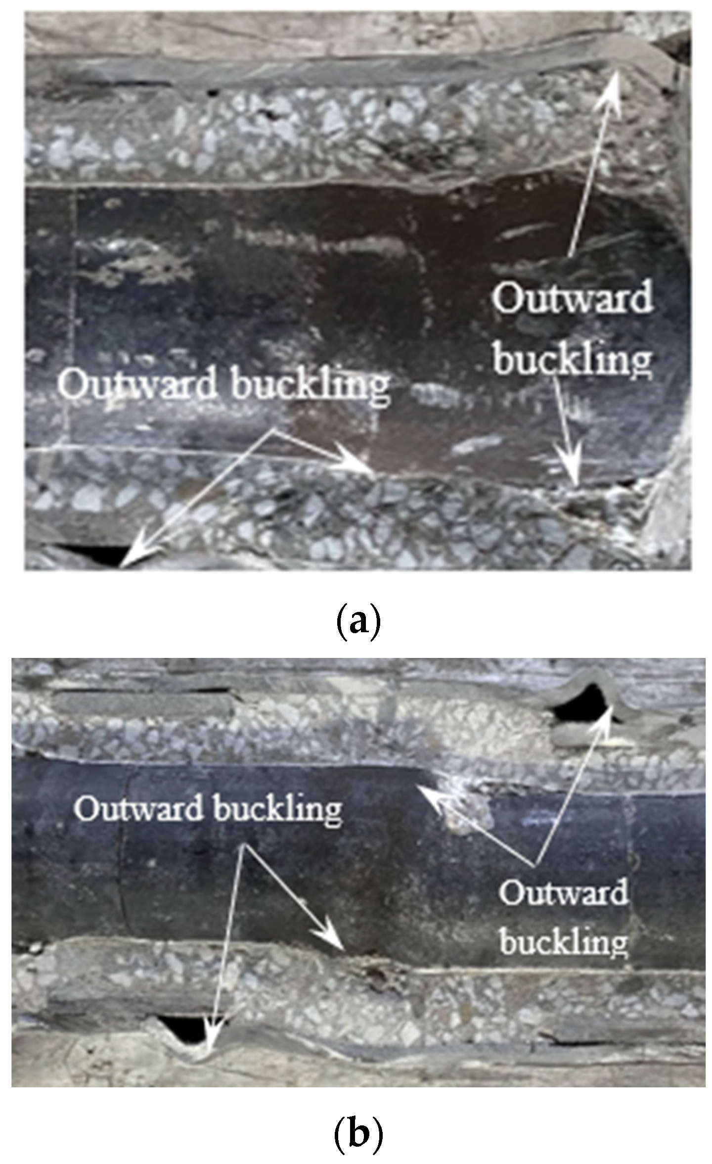
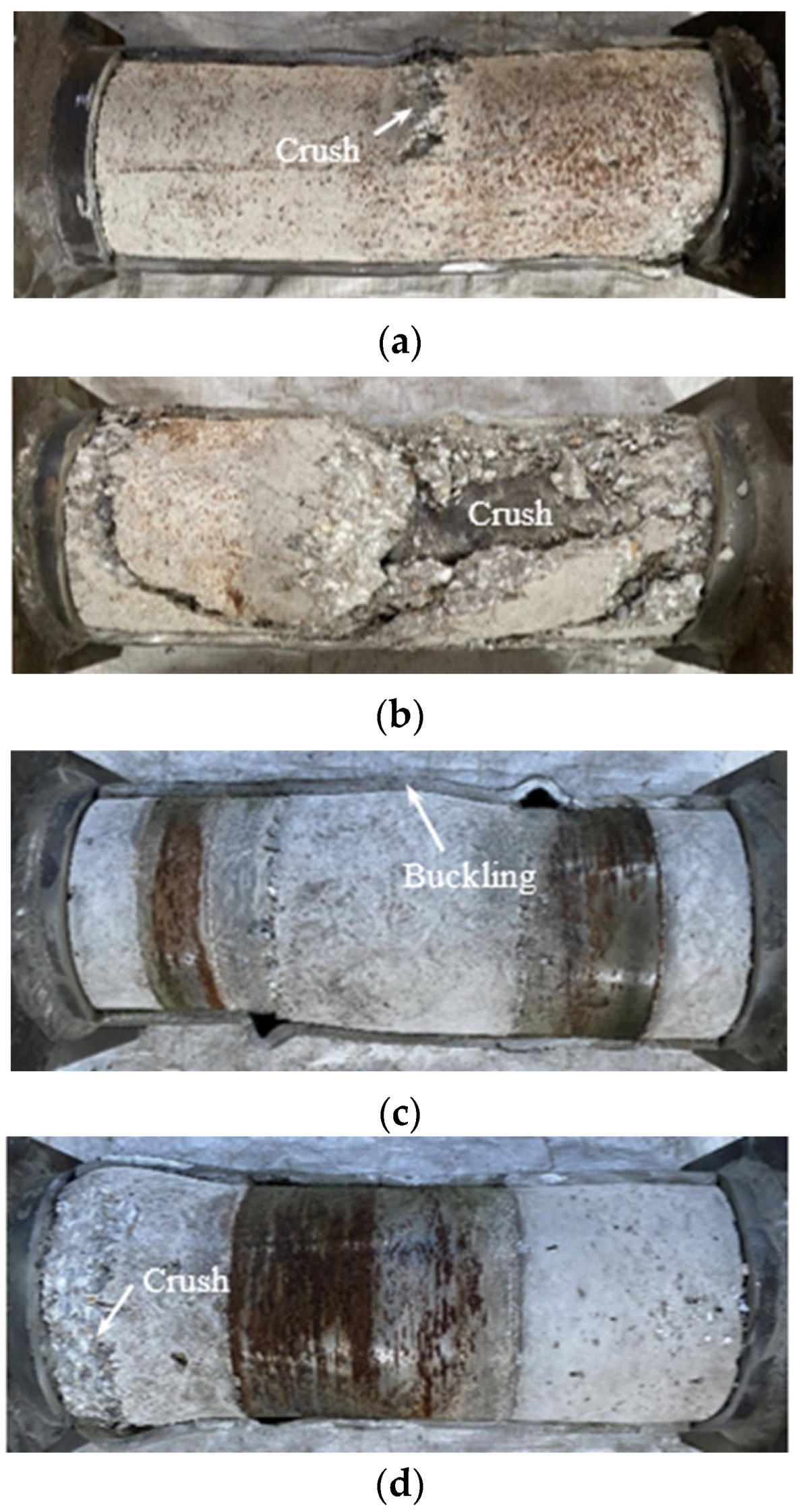
3. Specimen Failure Model
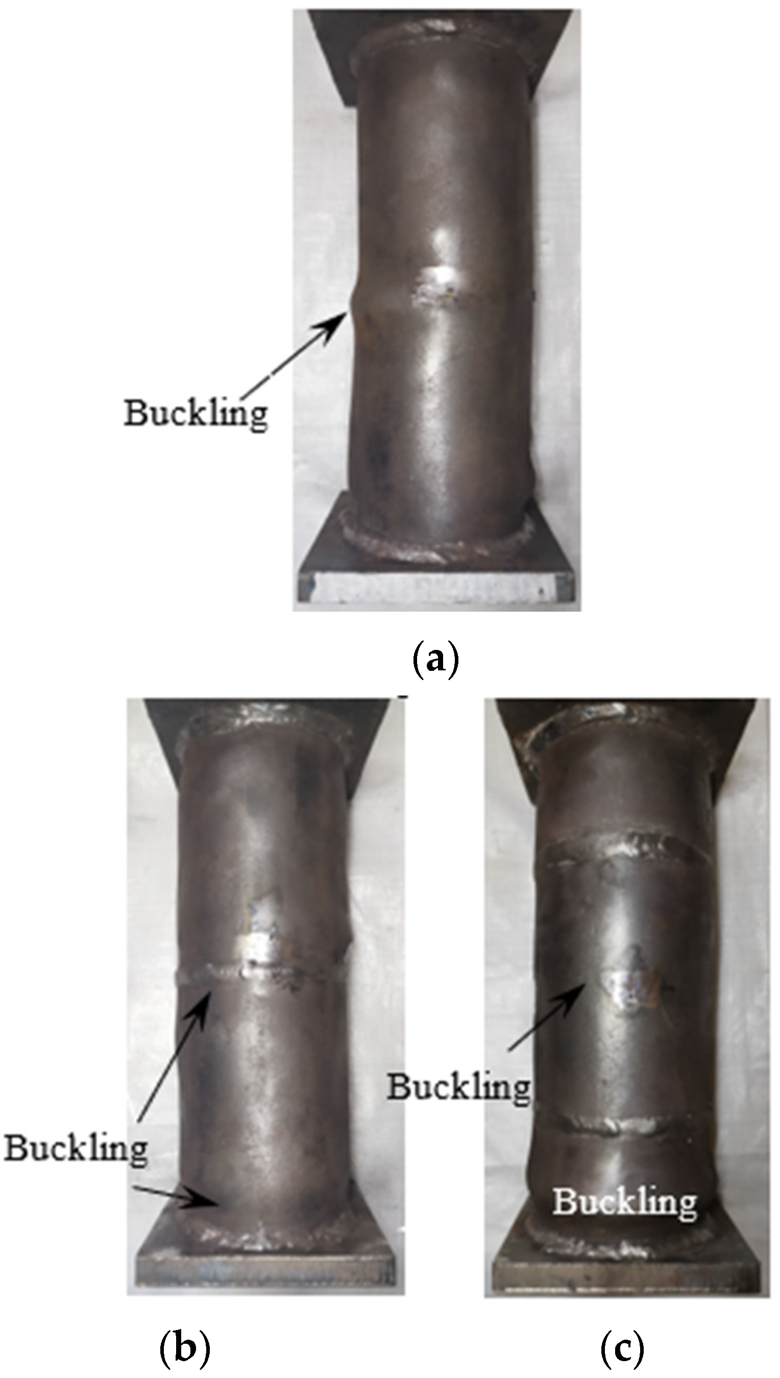
3.1. Outer Steel Tube
3.2. Inner Steel Tube
3.3. Concrete
4. Curve Analysis
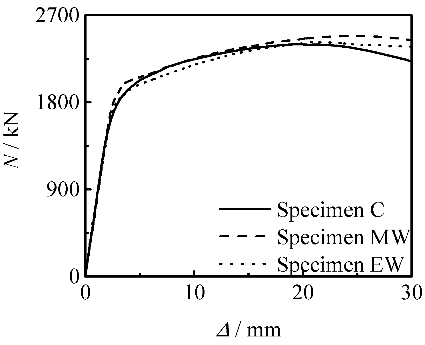
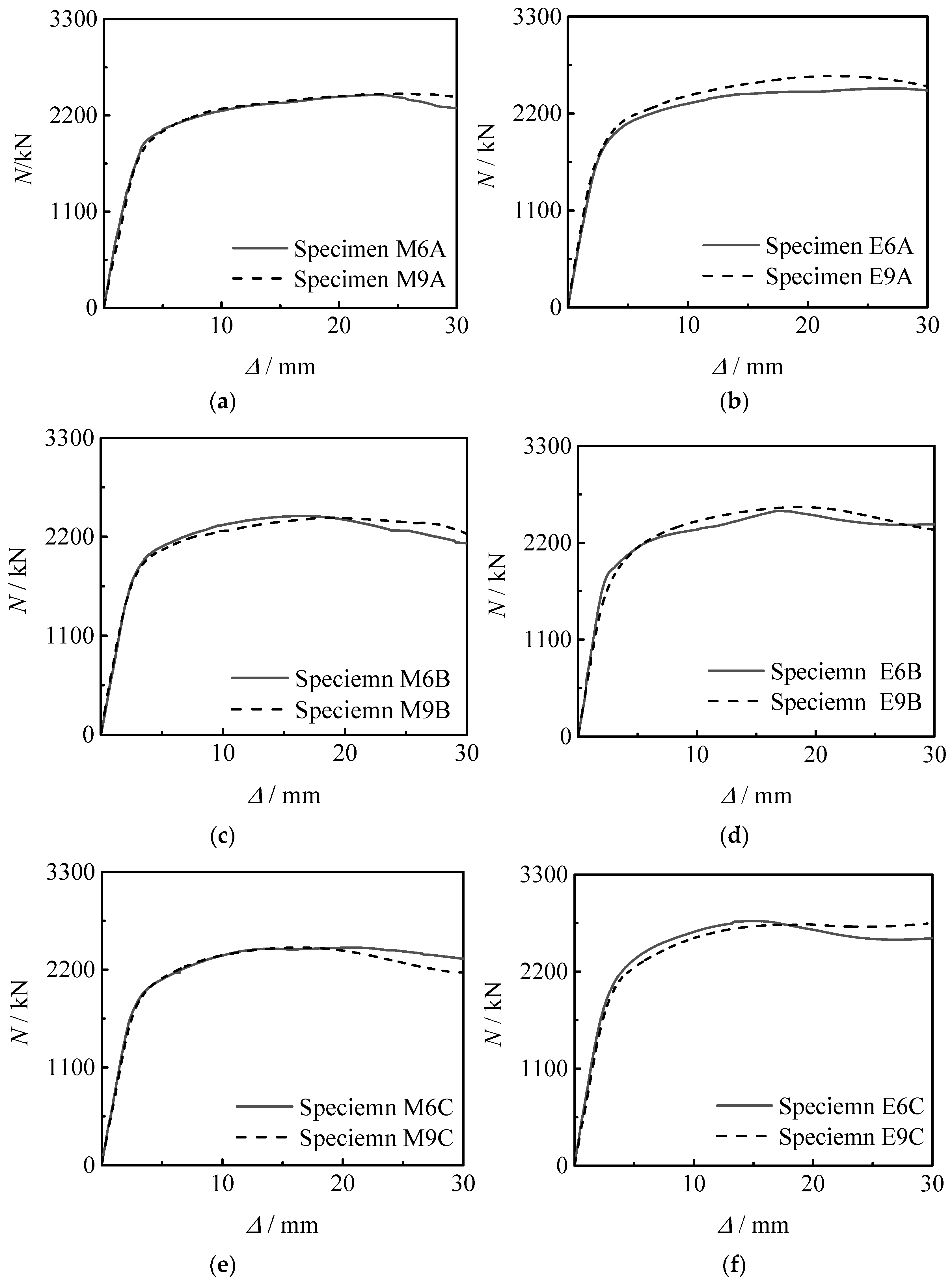
4.1. N-Δ Curve
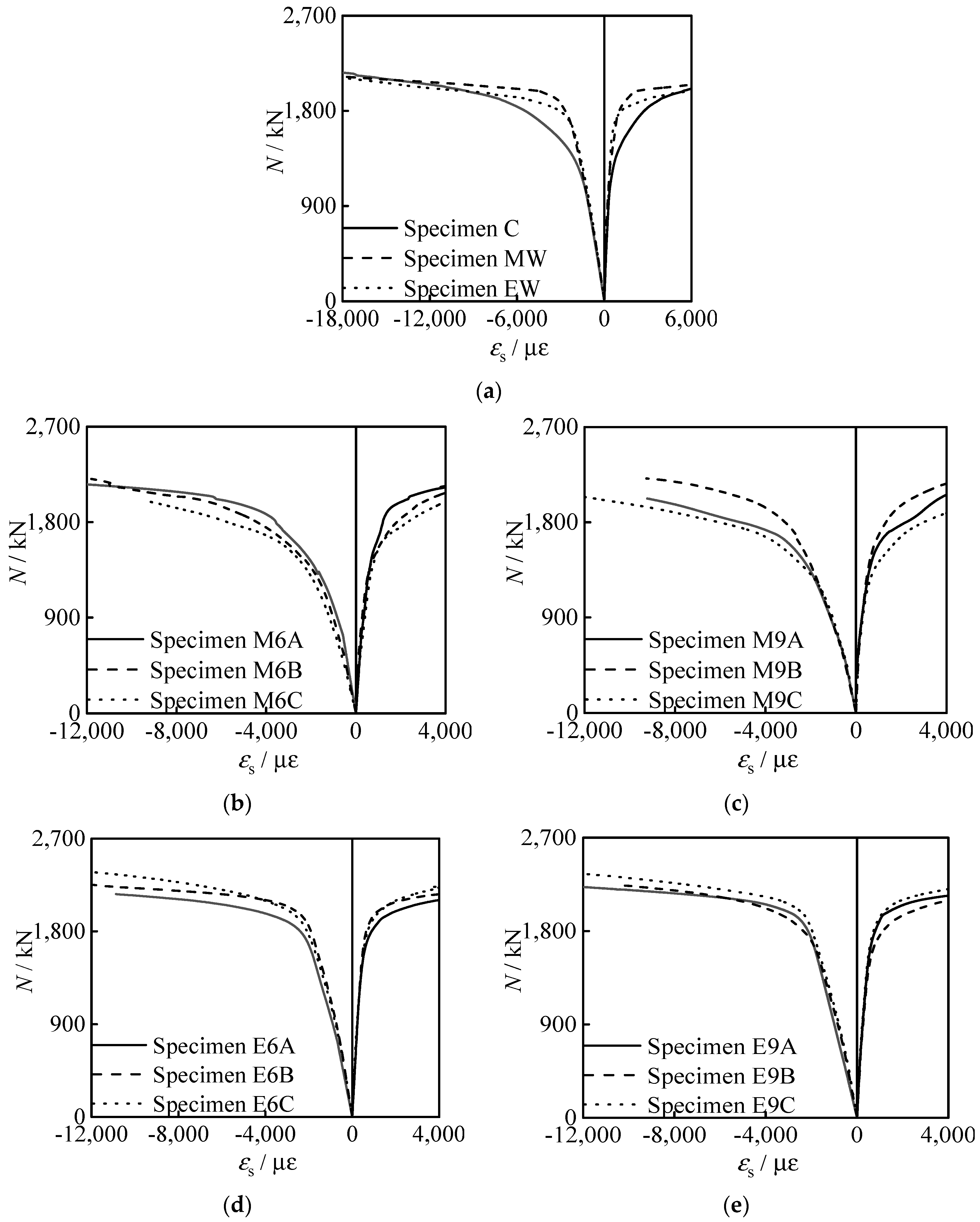
4.2. N-Steel Tube Strain (εs) Curve
5. Analysis of Influencing Factors
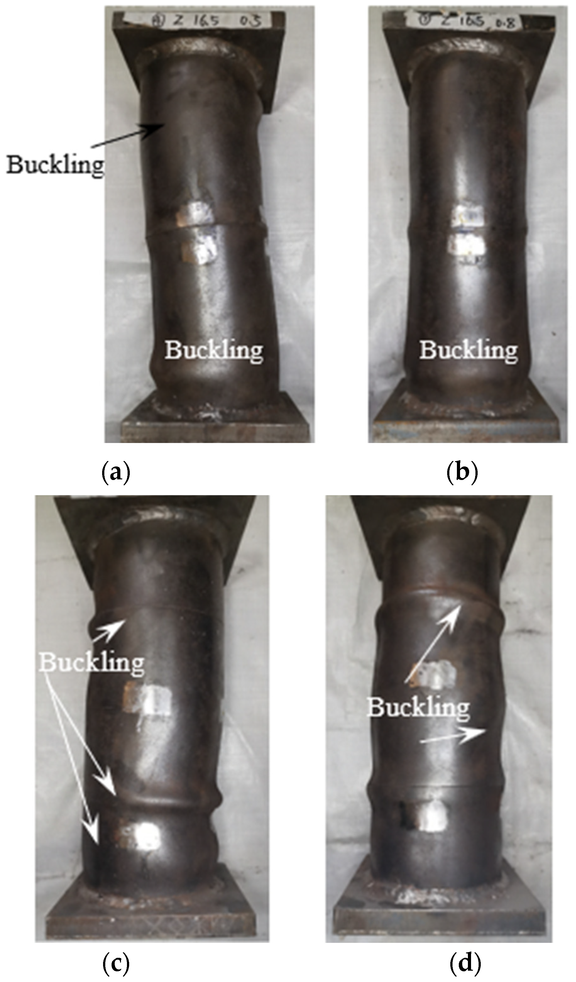
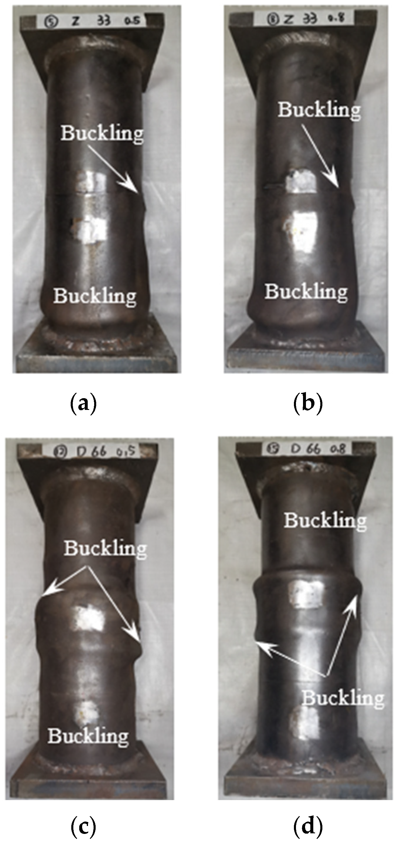
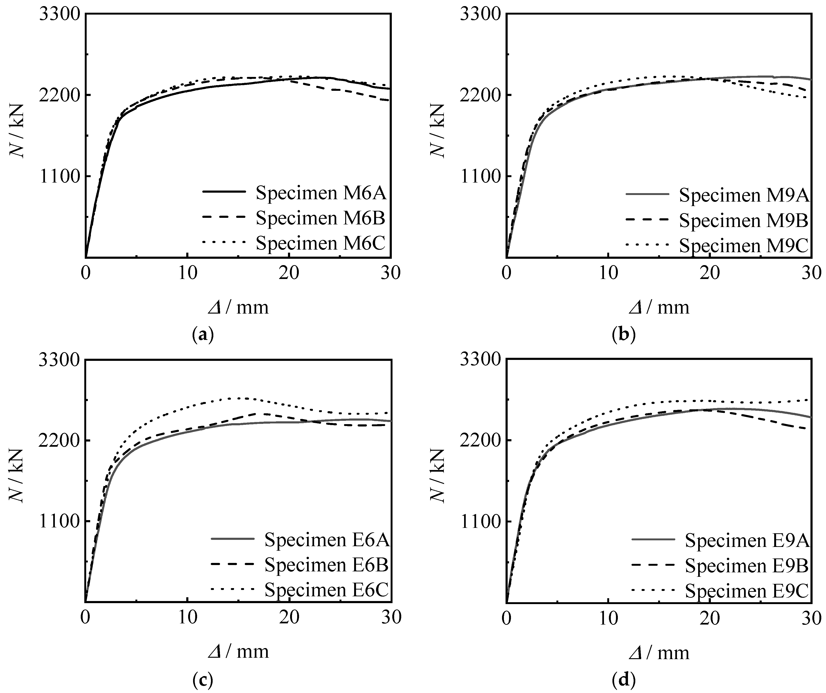
5.1. Thread Length
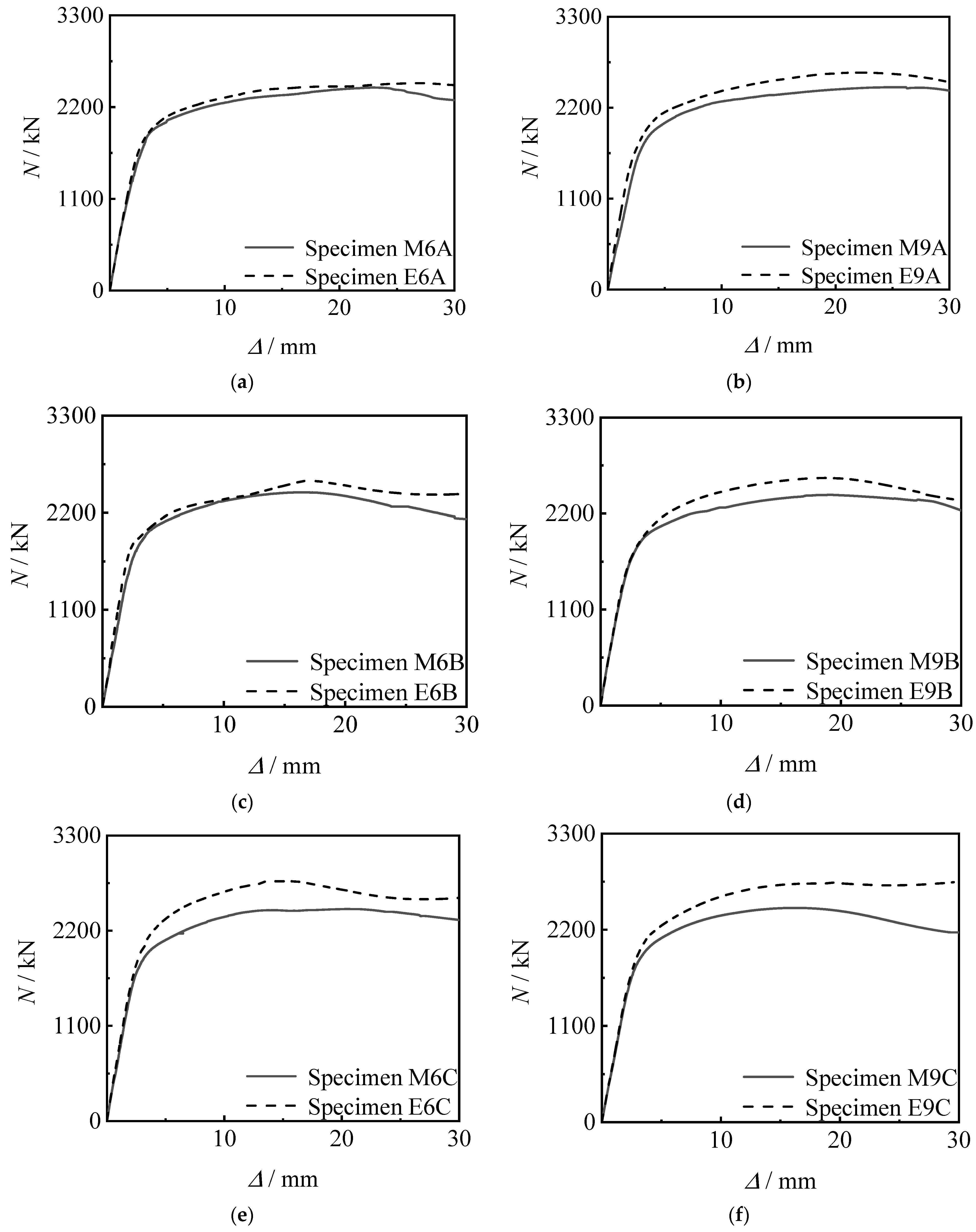
5.2. Thread Position
5.3. Thread Depth
6. Calculation of Load Bearing Capacity
7. Conclusions
- (1)
- The initial stage of the axial compressive loading–longitudinal compressive displacement curves of the hollow concrete-filled sandwich circular steel tubular specimens is the elastic stage, and the relationship between loading and displacement is linear. After that, the curves enter the elasto-plastic stage. With the gradual increase of displacement, the curves enter the yield-strengthening stage. After reaching the peak load, the load begins to drop, and curves enter the descending stage.
- (2)
- The bearing capacity and stiffness of the specimens connected by thread through the inner lining tube are not inferior to the welded specimen or the ordinary specimen.
- (3)
- The bearing capacity and stiffness of the specimens connected by thread through the inner lining tube increase with the increase of the thread length.
- (4)
- By comparing the corresponding references, the calculations of the axial compressive bearing capacity are suggested.
Author Contributions
Funding
Data Availability Statement
Conflicts of Interest
References
- Wei, S.; Mau, S.T.; Vipulanandan, C. Performance of new sandwich tube under axial loading: Analysis. J. Struct. Eng. ASCE 1995, 121, 1815–1821. [Google Scholar] [CrossRef]
- Zhao, X.L.; Grzebieta, R.H.; Ukur, A.; Elchalakani, M. Tests of concrete-filled double skin (SHS outer and CHS inner) composite stub columns. In Proceedings of the Third International Conference on Advances in Steel Structures, Hong Kong, China, 9–11 December 2002; Volume I, pp. 567–574. [Google Scholar]
- Ci, J.; Ahmed, M.; Liang, Q.Q.; Chen, S.; Chen, W.; Sennah, K.; Hamoda, A. Experimental and numerical investigations into the behavior of circular concrete-filled double steel tubular slender columns. Eng. Struct. 2022, 267, 114644. [Google Scholar] [CrossRef]
- Dong, L.; Zhang, W.L. Ultimate compressive capacity of tapered concrete-filled double skin steel tubular stub columns with large hollow ratio. J. Constr. Steel Res. 2022, 196, 107356. [Google Scholar]
- Thang, V.; Marshall, P. Studded bond enhancement for steel-concrete-steel sandwich shells. Ocean. Eng. 2015, 15, 31–39. [Google Scholar] [CrossRef]
- Ahmed MM, Z.; El-Sayed Seleman, M.M.; Touileb, K.; Albaijan, I.; Habba, M.I.A. Microstructure, crystallographic texture, and mechanical properties of friction stir welded mild steel for shipbuilding applications. Materials 2022, 15, 2905. [Google Scholar] [CrossRef] [PubMed]
- Yan, L.S.; Wei, X.W.; Wang, H.; Wei, B. Mechanical behaviour of circular steel-reinforced concrete-filled steel tubular members under pure bending loads. Structures 2020, 112, 8–25. [Google Scholar]
- Jiang, S.C.; Wang, Z.; Zhao, X.L. Structural performance of prestressed grouted pile-to-sleeve connection. J. Constr. Steel Res. 2023, 201, 107689. [Google Scholar] [CrossRef] [Green Version]
- Sun, W.-b. Experimental study grouting concrete filled steel tube column sleeve connection capacity. Eng. Struct. 2022, 267, 114600. [Google Scholar] [CrossRef]
- Wang, W.-d.; Yi, L.-b.; Fan, J.-h. Analysis of bending performance of inner and outer flange connections of circular concrete-filled double skin steel tubular (CFDST) member. J. Archit. Civ. Eng. 2020, 37, 42–51. [Google Scholar]
- Yi, L.-b. Research on mechanical properties of inner and outer flange connections of tapered concrete-filled double skin steel tube members. J. Lanzhou Univ. Technol. 2020, 6, 77–81. [Google Scholar]
- Deng, H.; Song, X.; Chen, Z.; Fu, P.; Dong, J. Experiment and design methodology of a double-layered flange connection in axial loads. Eng. Struct. 2018, 175, 436–456. [Google Scholar] [CrossRef]
- Grundy, P.; Kiuj, F. Prestress enancement of grouted pile/sleeve connections. In Proceedings of the First International Offshores and Polar Engineering Conference, ISOPE, Edinburgh, UK, 11–16 August 1991; Volume 1, pp. 130–136. [Google Scholar]
- Zhai, S.-s. Study on axial compression performance of concrete filled steel tubular columns with inner casing connections. J. Zhongyuan Univ. Technol. 2018, 7, 18–99. [Google Scholar]
- Yang, H.; Yu, Y.; Kang, L.; Chen, J.; Luo, Y. Research on the mechanical behavior of flange connected concrete filled steel tubular column-steel beam reinforced ring joints. J. Build. Struct. 2022, 43, 157–162. [Google Scholar]
- Wang, J.; Chen, J. The effect of connection methods on the axial tensile properties of concrete-filled steel tubular members with internal lattice angle steel. J. Build. Struct. 2019, 40, 354–361. [Google Scholar]
- Lei, Y.; Ling, Z. Study on stainless steel blind bolted T-stub to concrete-filled stainless steel tube connections. Eng. Struct. 2022, 257, 114107. [Google Scholar] [CrossRef]
- DBJ/T 13-51-2020; Technical Specification for Concrete-Filled Double Skin Steel Tubular Structures. China Architecture & Building Press: Beijing, China, 2020.
- Tao, Z.; Yu, Q. New Composite Structural Column—Experiment, Theory and Method; Science Press: Beijing, China, 2006. [Google Scholar]
- Huang, H. Performance analysis of hollow sandwich concrete filled steel tubular short columns. Structures 2010, 25, 81–82. [Google Scholar]
- Su, H.T.; Han, F.X. Experimental study on axial compression of circular hollow sandwich steel tube self compacting concrete short columns based on changes in void fraction. Concrete 2018, 7, 13–18. [Google Scholar]
- Wang, Z.B.; Guo, J. Research on the axial compression performance of hollow sandwich thin-walled steel tube concrete short columns. Prog. Build. Steel Struct. 2020, 20, 7. [Google Scholar]
- Cong, S.P.; Peng, M. Axial compression performance test of square hollow sandwich steel tube concrete short columns. Chin. Sci. Technol. Pap. 2019, 14, 1085–1089. [Google Scholar]
- Ni, G. Analysis of axial compression performance of hollow sandwich steel tube concrete columns with outer circle and inner square. Low Temp. Build. Technol. 2019, 41, 5–10. [Google Scholar]
- Xu, P.; Liu, Q. Experimental study on axial compression of circular hollow sandwich steel pipe self compacting concrete short columns based on changes in diameter to thickness ratio. Concrete 2019, 6, 10–19. [Google Scholar]
- Yan, X.F.; Zhao, Y.G. Compressive strength of axially loaded circular concrete-filled double-skin steel tubular short columns. J. Constr. Steel Res. 2020, 170, 106–114. [Google Scholar] [CrossRef]
- Tao, Z.; Han, L.H.; Zhao, X.L. Behaviour of concrete-filled double skin (CHS inner and CHS outer) steel tubular stub columns and beam-columns. J. Constr. Steel Res. 2004, 60, 1129–1158. [Google Scholar] [CrossRef]
- EN 1994-1-1:2004; Design of Composite Steel and Concrete Structures-Part1-1: General Rules and Rules for Buildings: Eurocode 4. European Committee for Standardization: Brussels, Belgium, 2004.
- ANSI/AISC 360-16; Specification for Structural Steel Buildings. American Institute of Steel Construction: Chicago, IL, USA, 2016.
- GB 50936-2014 (GB50936-2014); Technical Code for Concrete Filled Steel Tubular Structures. China Architecture & Building Press: Beijing, China, 2014.


| No. | Weld/Thread Position | h/mm | l/mm |
|---|---|---|---|
| C | – | – | – |
| MW | Middle section | – | – |
| EW | End section | – | – |
| M6A | Middle section | 0.6 | 16.5 |
| M6B | Middle section | 0.6 | 33 |
| M6C | Middle section | 0.6 | 66 |
| M9A | Middle section | 0.9 | 16.5 |
| M9B | Middle section | 0.9 | 33 |
| M9C | Middle section | 0.9 | 66 |
| E6A | End section | 0.6 | 16.5 |
| E6B | End section | 0.6 | 33 |
| E6C | End section | 0.6 | 66 |
| E9A | End section | 0.9 | 16.5 |
| E9B | End section | 0.9 | 33 |
| E9C | End section | 0.9 | 66 |
| Type | fy/MPa | fu/MPa | Es/GPa | vs | δ |
|---|---|---|---|---|---|
| Outer steel tube | 420 | 570 | 215 | 0.28 | 20.7 |
| Outer inner lining tube | 419 | 569 | 210 | 0.27 | 25.9 |
| Inner steel tube | 509 | 624 | 211 | 0.23 | 21.3 |
| Inner inner lining tube | 396 | 517 | 207 | 0.27 | 21.0 |
| No. | Test Values Nue/kN | Nuc/Nue | |||
|---|---|---|---|---|---|
| Reference [17] | Reference [28] | Reference [29] | Reference [30] | ||
| M6A | 2040 | 0.93 | 0.91 | 0.91 | 0.77 |
| M6B | 2090 | 0.90 | 0.89 | 0.89 | 0.75 |
| M6C | 2091 | 0.90 | 0.89 | 0.89 | 0.75 |
| M9A | 2017 | 0.94 | 0.92 | 0.92 | 0.78 |
| M9B | 2053 | 0.92 | 0.91 | 0.90 | 0.77 |
| M9C | 2105 | 0.90 | 0.89 | 0.88 | 0.75 |
| E6A | 2088 | 0.90 | 0.89 | 0.89 | 0.76 |
| E6B | 2146 | 0.88 | 0.87 | 0.86 | 0.73 |
| E6C | 2337 | 0.81 | 0.80 | 0.79 | 0.67 |
| E9A | 2147 | 0.88 | 0.87 | 0.86 | 0.73 |
| E9B | 2150 | 0.88 | 0.87 | 0.86 | 0.73 |
| E9C | 2245 | 0.84 | 0.83 | 0.83 | 0.70 |
| Average value | 0.89 | 0.88 | 0.87 | 0.74 | |
| Standard deviation | 0.036 | 0.034 | 0.036 | 0.031 | |
Disclaimer/Publisher’s Note: The statements, opinions and data contained in all publications are solely those of the individual author(s) and contributor(s) and not of MDPI and/or the editor(s). MDPI and/or the editor(s) disclaim responsibility for any injury to people or property resulting from any ideas, methods, instructions or products referred to in the content. |
© 2023 by the authors. Licensee MDPI, Basel, Switzerland. This article is an open access article distributed under the terms and conditions of the Creative Commons Attribution (CC BY) license (https://creativecommons.org/licenses/by/4.0/).
Share and Cite
Wang, Q.; Zhao, J.; Peng, K. Test on Compressive Performance of Hollow Concrete-Filled Sandwich Circular Steel Tubes Connected by Thread. Metals 2023, 13, 1207. https://doi.org/10.3390/met13071207
Wang Q, Zhao J, Peng K. Test on Compressive Performance of Hollow Concrete-Filled Sandwich Circular Steel Tubes Connected by Thread. Metals. 2023; 13(7):1207. https://doi.org/10.3390/met13071207
Chicago/Turabian StyleWang, Qingli, Jie Zhao, and Kuan Peng. 2023. "Test on Compressive Performance of Hollow Concrete-Filled Sandwich Circular Steel Tubes Connected by Thread" Metals 13, no. 7: 1207. https://doi.org/10.3390/met13071207